Sierra Wireless AR5550 Dual band (800 & 1900) CDMA 1X & EVDO Module User Manual AirPrime AR Series Product Specification
Sierra Wireless Inc. Dual band (800 & 1900) CDMA 1X & EVDO Module AirPrime AR Series Product Specification
UserManual.wiki
>
Sierra Wireless
>
AR5550 User Manual
Manual
Navigation menu
Upload a User Manual
Namespaces
Wiki Guide
HTML
PDF
Info
Views
User Manual
Discussion / Help
Navigation

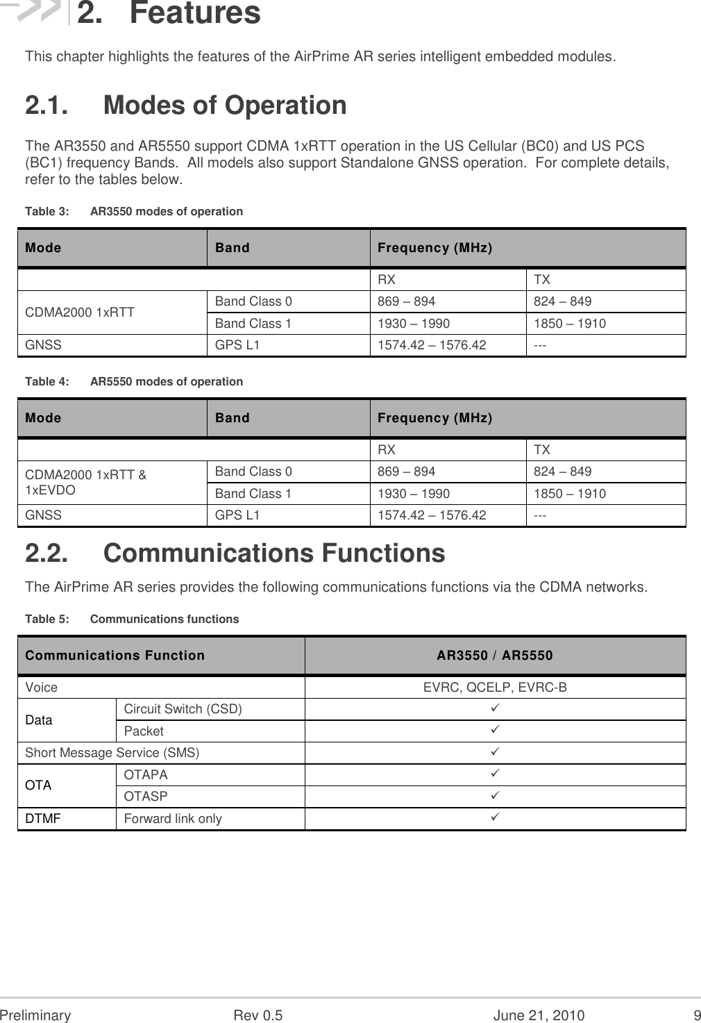
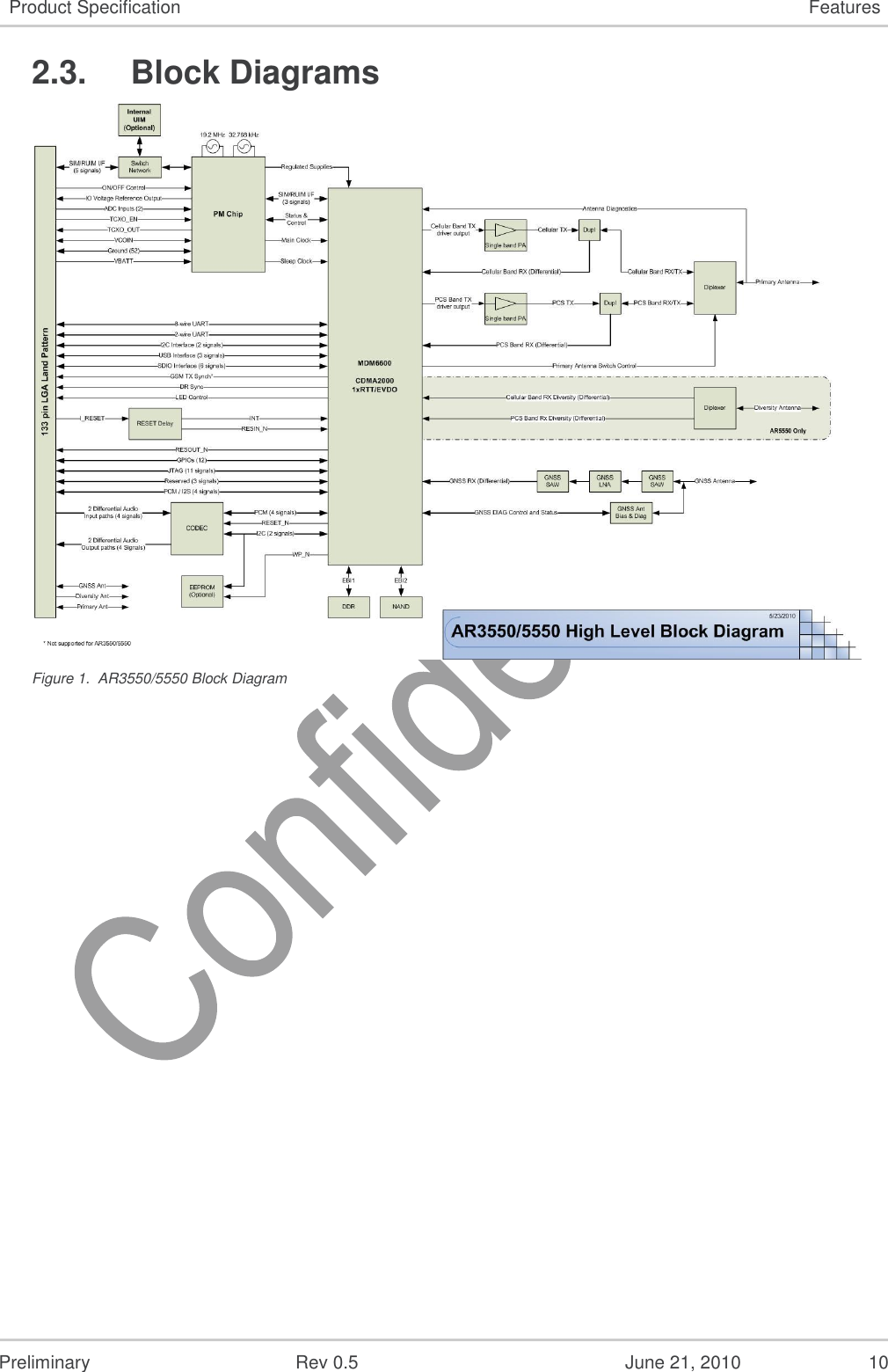
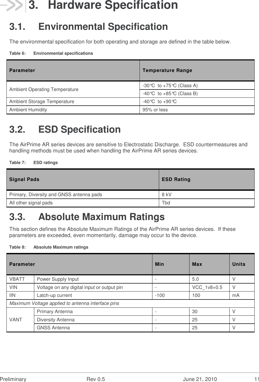
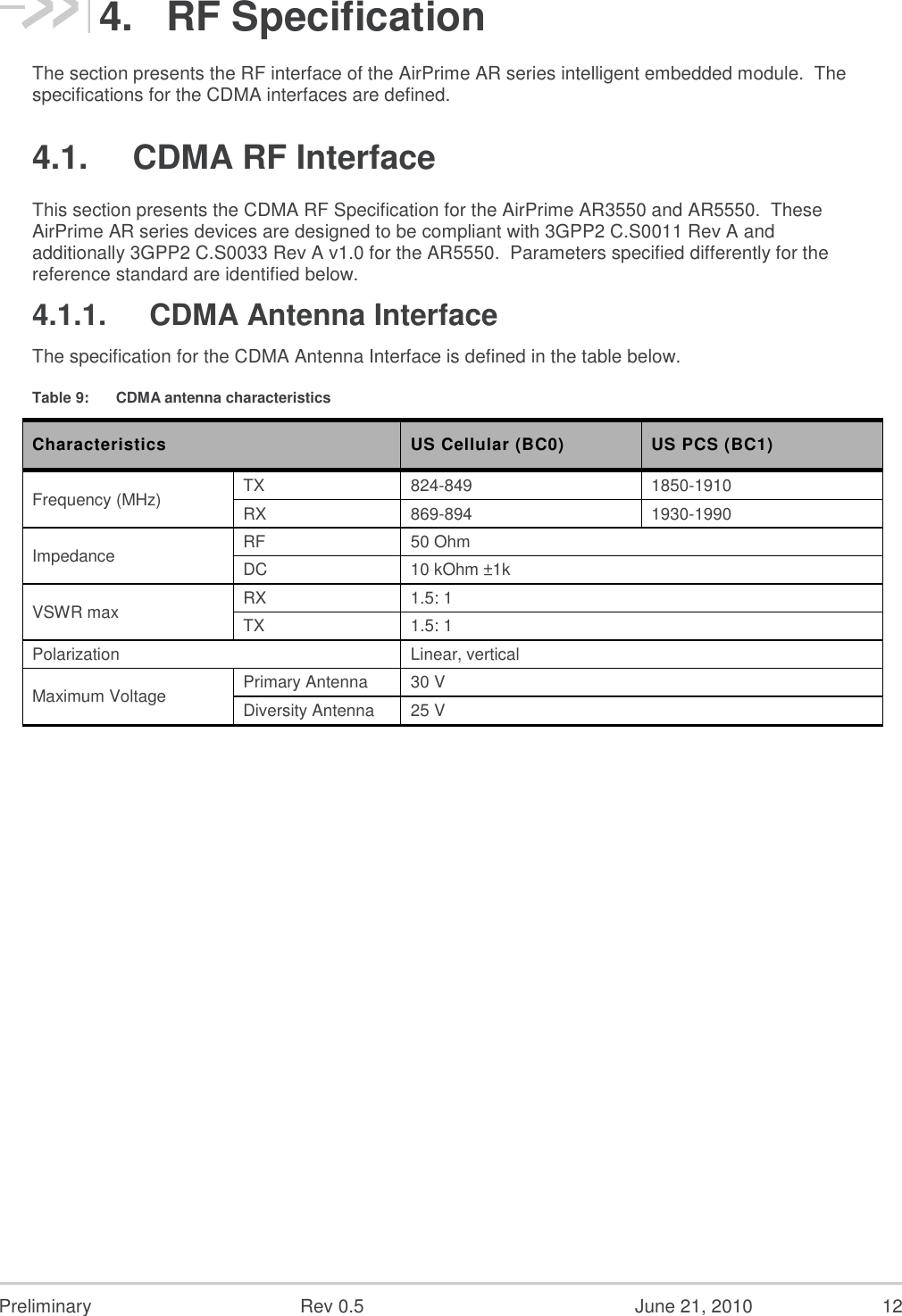
![Preliminary Rev 0.5 June 21, 2010 8 1. Overview This document is the Hardware Product Specification for the AirPrime AR series of intelligent embedded modules. It defines the high level product features and illustrates the interfaces for these features. This document is intended to cover the hardware aspects of the product series, including electrical and mechanical. The AirPrime AR series of intelligent embedded modules are designed for the automotive industry and any market with similar quality and life-time support requirements. They support several air interface standards but share a common form-factor and electrical interface. All versions also have Global Navigation Satellite System (GNSS) capabilities via GPS. The AirPrime AR series of intelligent embedded modules are based on the Qualcomm MDM6200 and MDM6600 wireless chipsets. The term AirPrime AR series addresses all of the following specific products. Table 1: AirPrime AR series intelligent embedded modules Product Description Band Support AR3550 CDMA2000 1xRTT intelligent embedded module BC0, BC1 AR5550 CDMA2000 1xEVDO intelligent embedded module BC0, BC1 1.1. Reference Specifications The table below lists the reference specifications for this product. Table 2: Reference specifications Ref Title Rev Issuer [1] Recommended Minimum Performance Standards for cdma2000 High Rate Packet Data Access Terminal – C.S0033 A v1.0 3GPP2 [2] Recommended Minimum Performance Standards for cdma2000 Spread Spectrum Mobile Stations – C.S0011 (IS-98D) A 3GPP2 [3] Universal Serial Bus Specification 2.0 USB Implementers Forum [4] Universal Serial Bus CDC Subclass Specification for Wireless Mobile Communication Devices 1.0 USB Implementers Forum [5] Universal Serial Bus Class Definitions for Communication Devices 1.1 USB Implementers Forum [6] AirPrime AR Series LGA Specification 0.5 Sierra Wireless](https://usermanual.wiki/Sierra-Wireless/AR5550/User-Guide-1385812-Page-8.png)