Sierra Wireless AR7552 Cellular/PCS WCDMA/LTE Modem User Manual Hardware Integration Guide
Sierra Wireless Inc. Cellular/PCS WCDMA/LTE Modem Hardware Integration Guide
UserManual.wiki
>
Sierra Wireless
>
AR7552 User Manual
AirPrime - AR7552 - Hardware Integration Guide - Rev1.0_v7
Navigation menu
Upload a User Manual
Namespaces
Wiki Guide
HTML
PDF
Info
Views
User Manual
Discussion / Help
Navigation
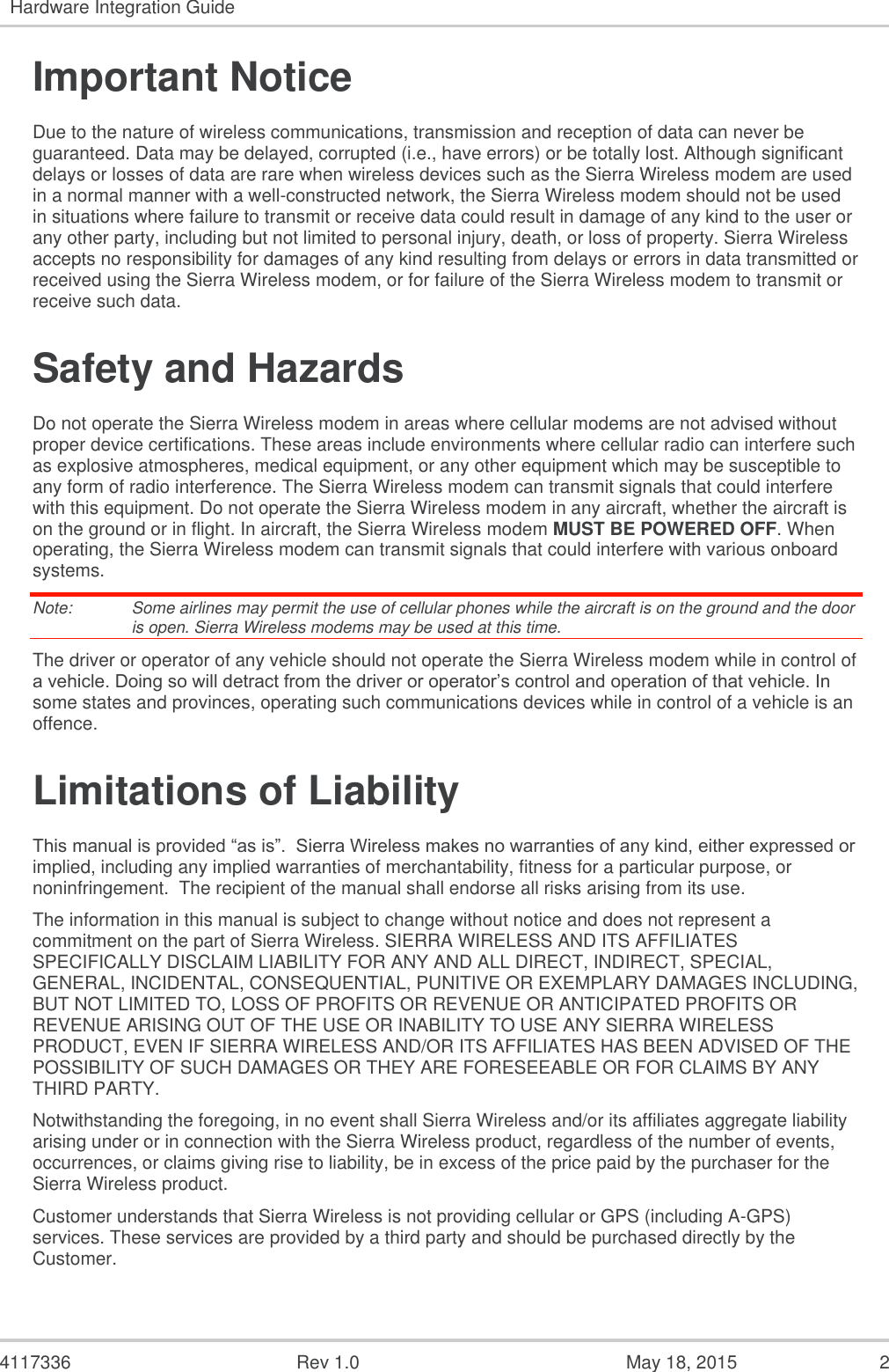
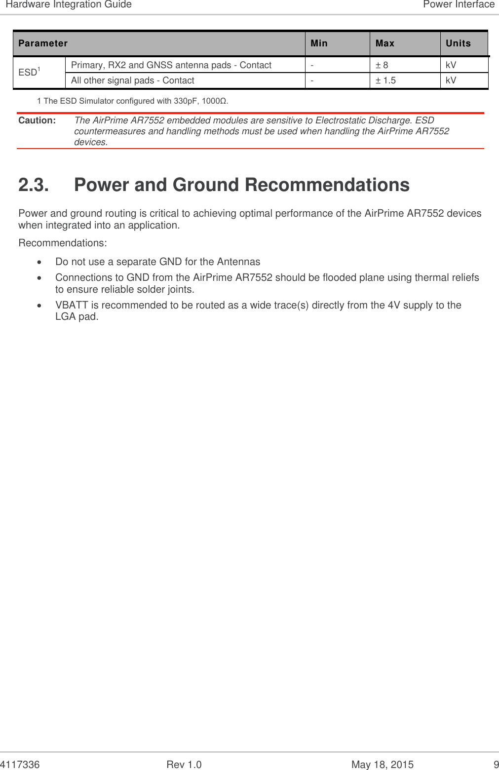
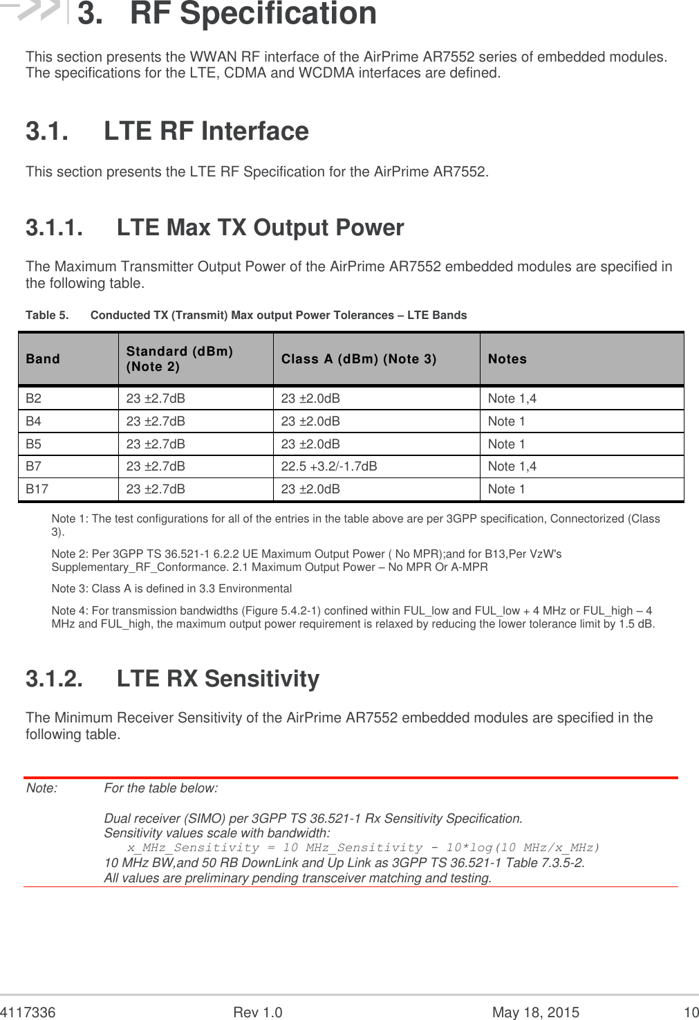
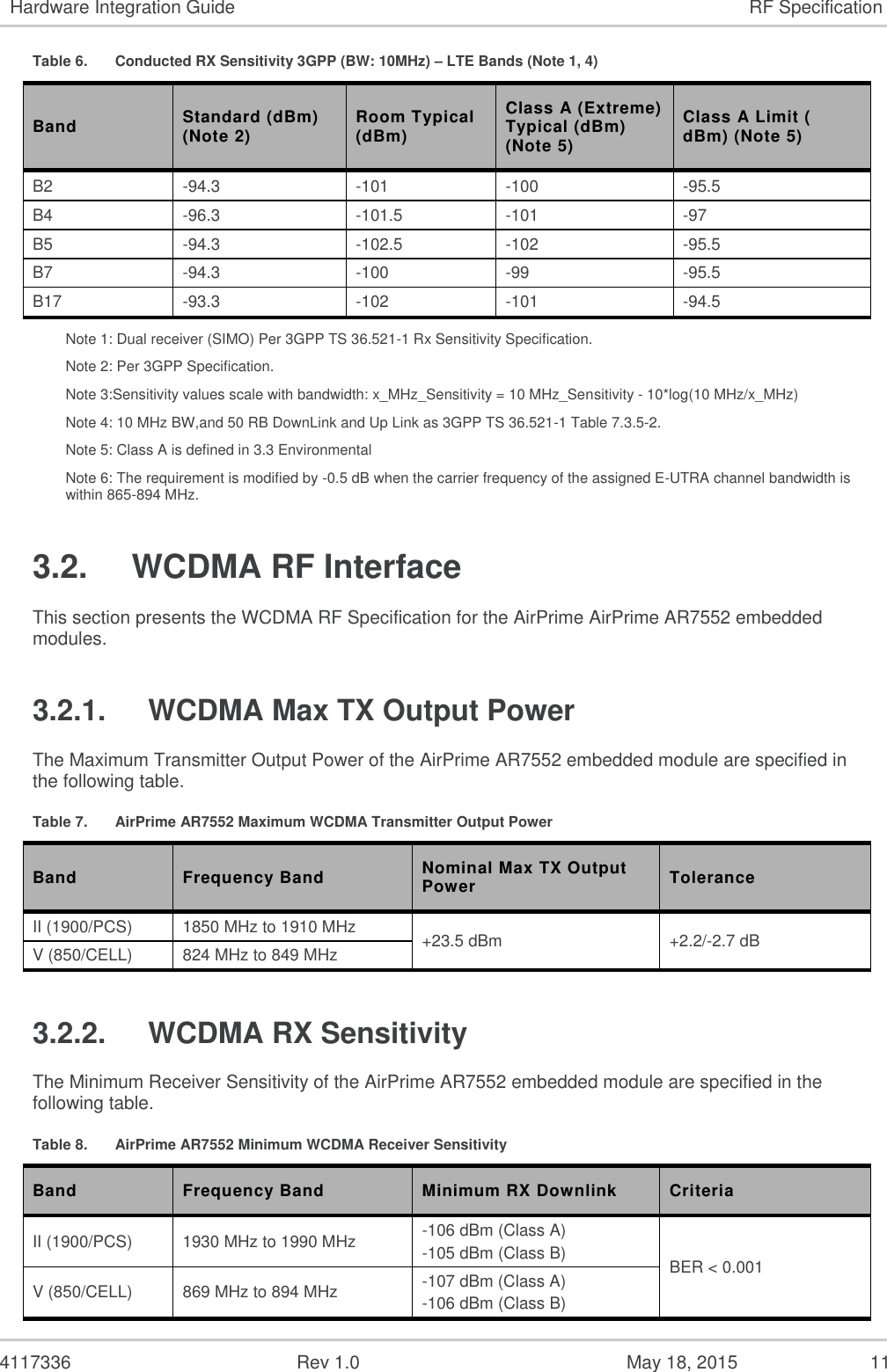
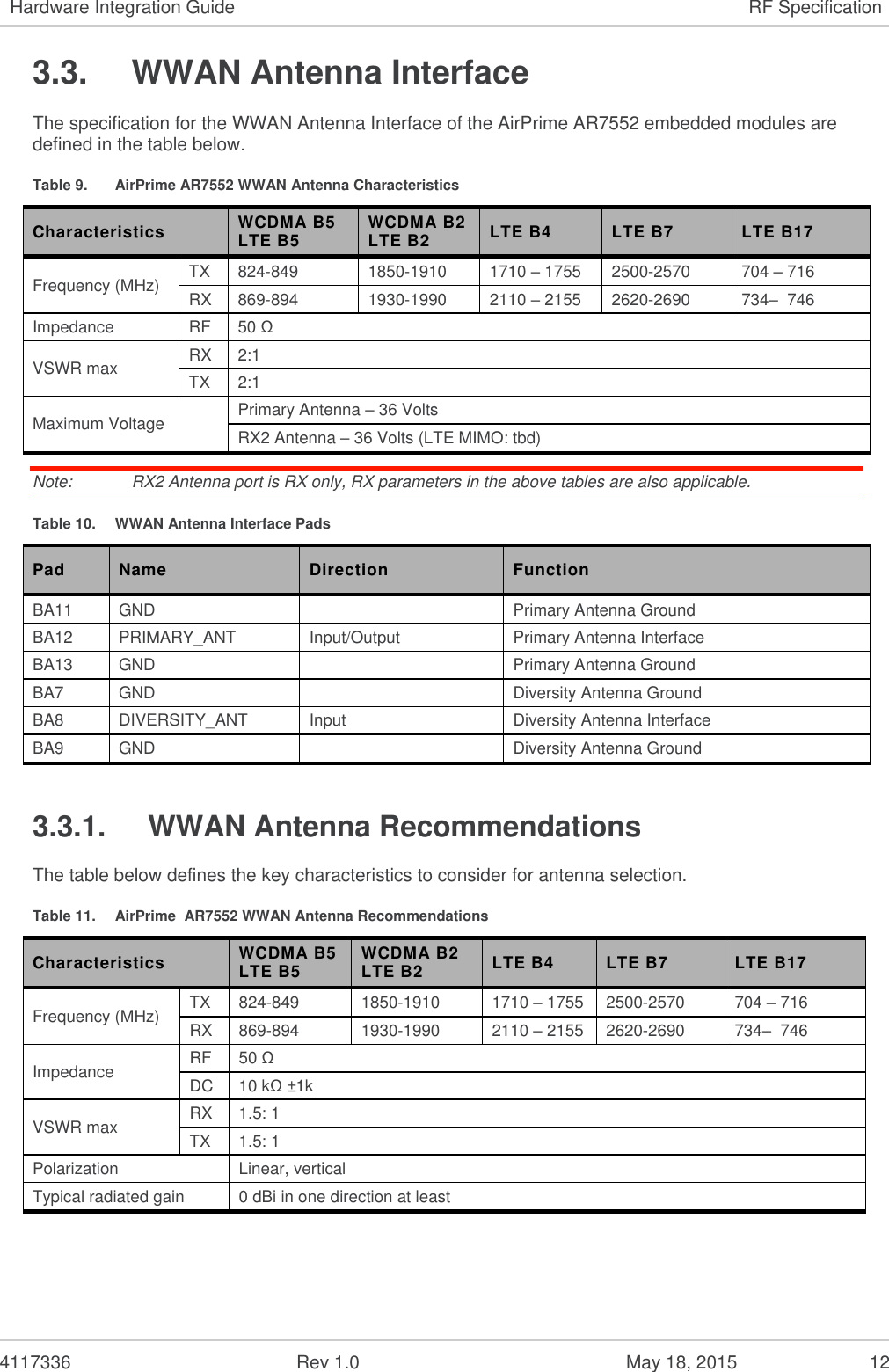
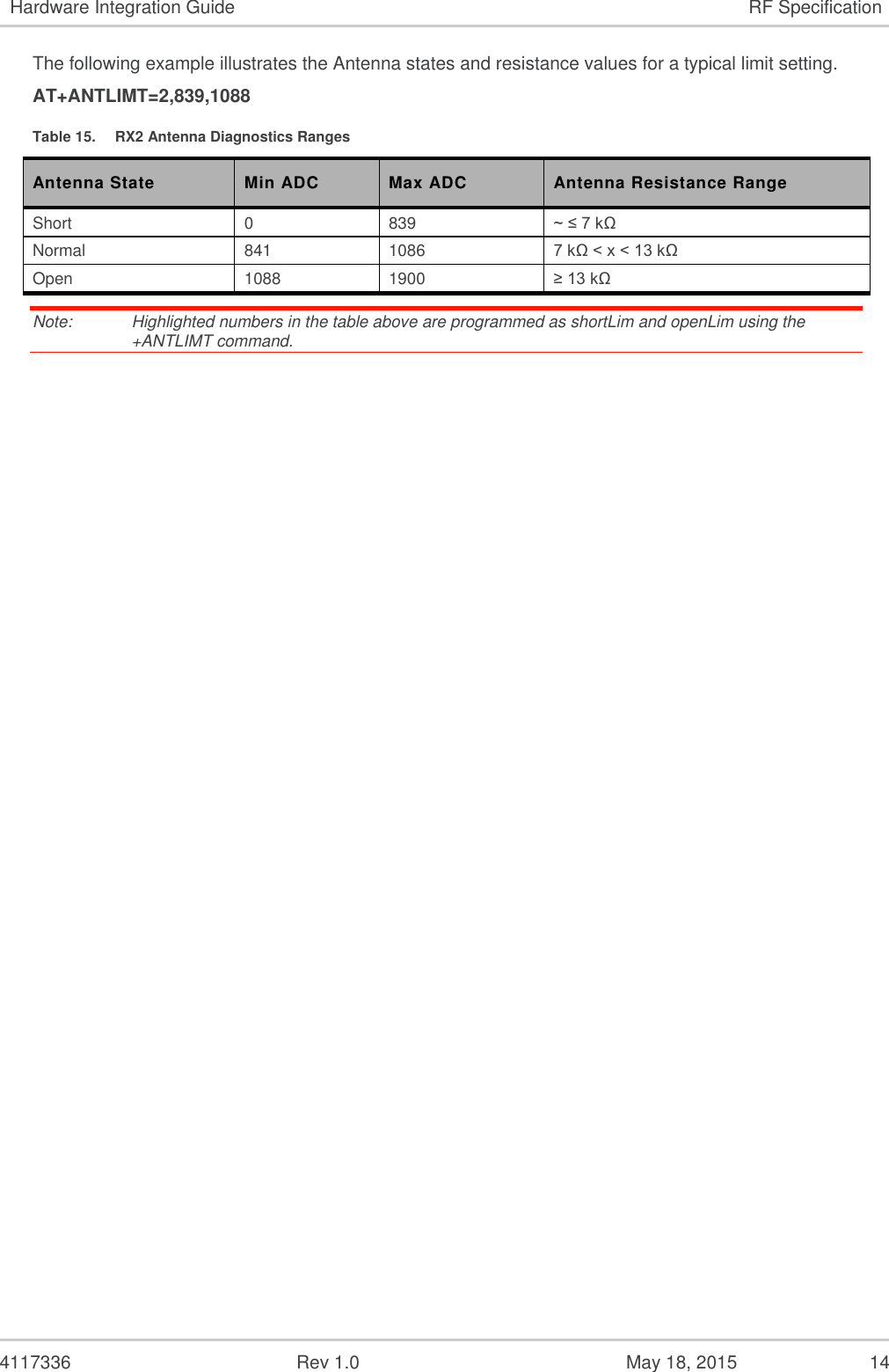
![4117336 Rev 1.0 May 18, 2015 13 Hardware Integration Guide RF Specification 3.4. Primary Antenna Diagnostics The primary antenna diagnostic feature allows the AirPrime AR7552 embedded module to determine if the primary antenna connected to the module is: open, shorted or normal. The antenna connected to this interface needs to have a DC resistance to ground of 10 kΩ ± 1k embedded inside. The ARx55x FW accepts two limits which are used to evaluate the status of the antenna, representing the short and open thresholds. Refer to document [7] for the syntax of AT+ANTLIMT. Table 12. Primary Antenna ADC Characteristics Min Nom Max Units ADC Voltage Range 0 0.9 1.8 Volts Resolution - 15 Bit ADC Values 0 16383 Voltage/ADC step ~0.0011 Volts 1 Assumes 10kΩ Nominal DC resistance in the attached antenna and internal to AirPrime AR7552 device The following example illustrates the Antenna states and resistance values for a typical limit setting. AT+ANTLIMT=1,839,1088 Table 13. Primary Antenna Diagnostics Ranges Antenna State Min ADC Max ADC Antenna Resistance Range Short 0 839 ~ ≤ 7 kΩ Normal 841 1086 7 kΩ < x < 13 kΩ Open 1088 1900 ≥ 13 kΩ Note: Highlighted numbers in the table above are programmed as shortLim and openLim using the +ANTLIMT command. 3.5. RX2 Antenna Diagnostics The RX2 antenna diagnostic feature allows the AirPrime AR75520 to determine if the RX2 antenna connected to the module is: open, shorted or normal. The antenna connected to this interface needs to have a DC resistance to ground of 10 kΩ ± 1k embedded inside. The AirPrime AR7552 FW accepts two limits which are used to evaluate the status of the antenna, representing the short and open thresholds. Refer to document [7] for the syntax of AT+ANTLIMT. Table 14. RX2 Antenna ADC Characteristics Min Nom Max Units ADC Voltage Range 0 0.9 1.8 Volts Resolution - 15 Bit ADC Values 0 16383 Voltage/ADC step ~0.0011 Volts 1 Assumes 10kΩ Nominal DC resistance in the attached antenna and internal to AirPrime AR7552 device](https://usermanual.wiki/Sierra-Wireless/AR7552/User-Guide-2647456-Page-13.png)
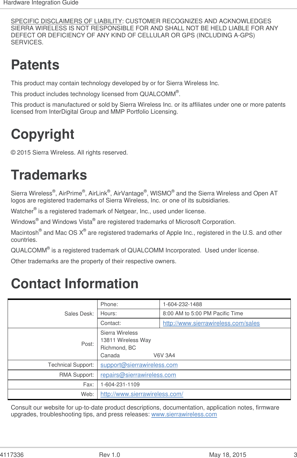
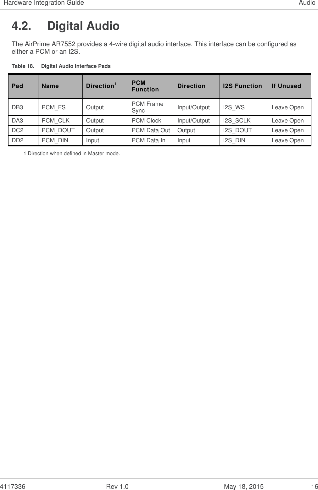
![4117336 Rev 1.0 May 18, 2015 15 4. Audio The AirPrime AR7552 supports both Analog and Digital audio interfaces. The following diagram illustrates the Audio subsystem and identifies where various AT commands affect the audio subsystem. Refer to document [7] for details of the AT commands. 4.1. Analog Audio The AirPrime AR7552 provides a mono differential analog audio interface. Table 16. Analog Audio Interface Pads Pad Name Direction Function Interface CD9 AUDIO1_IN_P Input Microphone 1 input positive Primary CC10 AUDIO1_IN_M Microphone 1 input negative CE6 AUDIO1_OUT_P Output Speaker 1 output positive CE8 AUDIO1_OUT_M Speaker 1 output negative Table 17. Analog Audio Interface Characteristics Analog Audio Min. Typ. Max. Units Audio IN Input Impedance 16 20 24 kΩ Signal Level – Differential -0.3 - 2.9 dBV Signal Level – Single-ended (the unused audio signal must be tied to GND or analog reference) -0.3 - 2.9 dBV Audio OUT Signal Level – Differential - - dBV Signal Level – Single-ended -0.3 - 2.9 dBV Output Impedance -0.3 - 2.9 Ω Signal Drive Strength – Application Load - 600 1M kΩ](https://usermanual.wiki/Sierra-Wireless/AR7552/User-Guide-2647456-Page-15.png)
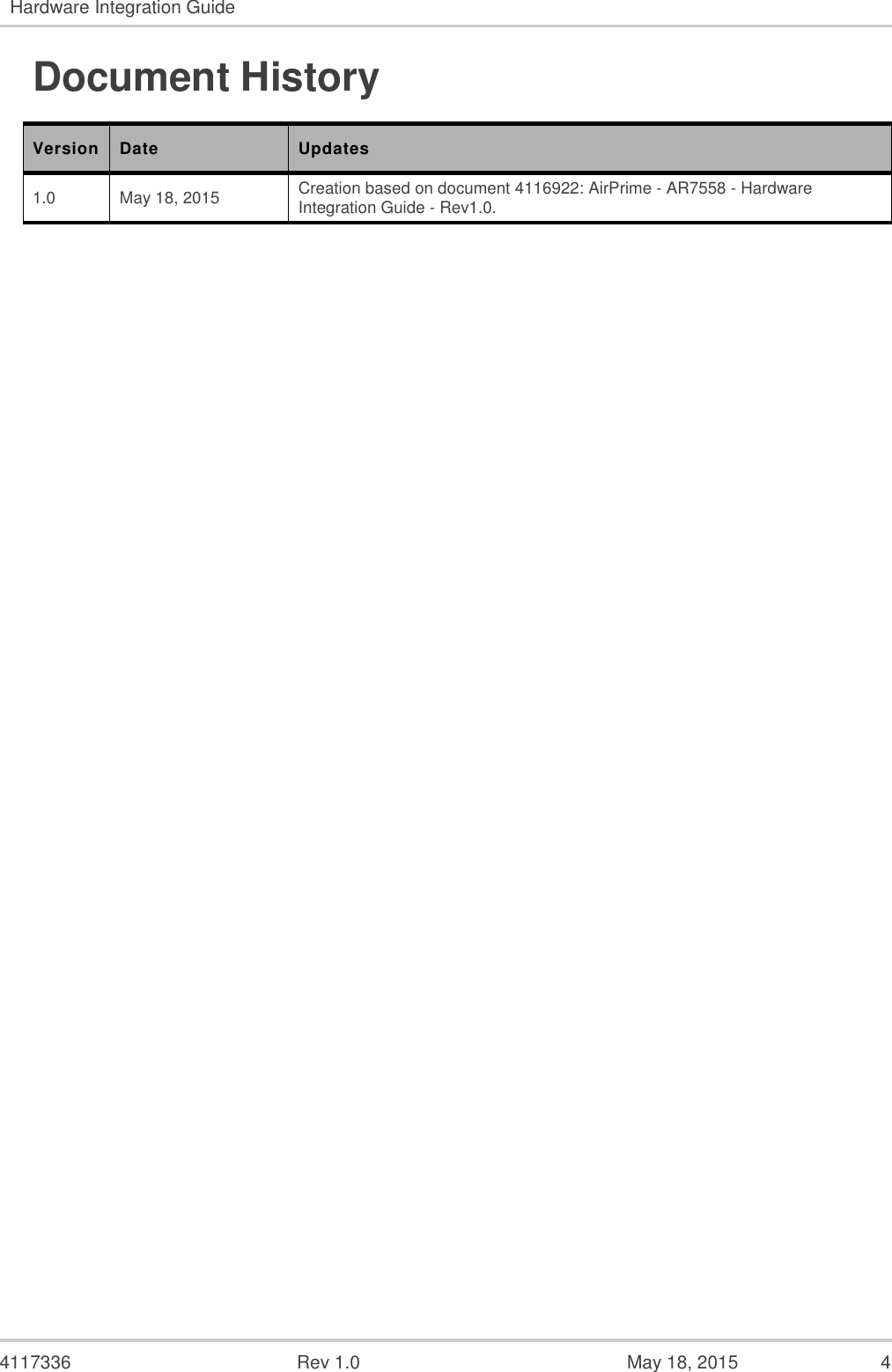
![4117336 Rev 1.0 May 18, 2015 24 7. References 7.1. Reference Documents The table below lists the reference specifications for this product. Table 21. Reference Specifications Ref Title Issuer [1] Recommended Minimum Performance Standards for cdma2000 High Rate Packet Data Access Terminal – C.S0033 3GPP2 [2] Recommended Minimum Performance Standards for cdma2000 Spread Spectrum Mobile Stations – C.S0011 (IS-98D) 3GPP2 [3] Universal Serial Bus Specification USB Implementers Forum [4] Universal Serial Bus CDC Subclass Specification for Wireless Mobile Communication Devices USB Implementers Forum [5] Universal Serial Bus Class Definitions for Communication Devices USB Implementers Forum [6] AirPrime AR Series Customer Process Guidelines Sierra Wireless [7] AirPrime AR7 Series AT Command Interface Specification Sierra Wireless [8] AirPrime AR7 Series Firmware Download Guide Sierra Wireless 7.2. Abbreviations The table below lists several abbreviations used in this document. Table 22. Abbreviations Abbreviation Description CDMA Code Division Multiple Access DRX Discontinuous Receive GNSS Global Navigation Satellite System GSM Global System for Mobile Communications HSPA High Speed Packet Access LTE Long Term Evolution SCI Slot Cycle Index USB Universal Serial Bus WCDMA Wideband Code Division Multiple Access WWAN Wireless Wide Area Network](https://usermanual.wiki/Sierra-Wireless/AR7552/User-Guide-2647456-Page-24.png)