Sierra Wireless C3310 Dual Mode, Dual Channel Modem User Manual users manual
Sierra Wireless, Inc. Dual Mode, Dual Channel Modem users manual
users manual

P
Pi
in
nP
Po
oi
in
nt
t
C
CD
DM
MA
A
User Guide
Version 1.0
AirLink Communications, Inc.
February 22, 2003
PinPoint CDMA User Guide Version 1.0
AirLink Communications, Inc. Page 1 February 22, 2003
Information in this document is subject to change without notice.
© Copyright AirLink Communications, Inc, 1993-2003. All rights reserved.
Please send comments to:
email: pubs@AirLink.com
Fax: 510-226-4299
Phone: 510-226-4200
Post: AirLink Communications, Inc.
Attention: Technical Publications Dept.
472 Kato Terrace
Fremont, CA 94539
Preface
AirLink Communications, Inc. Page i February 22, 2003
Important Notice
Because of the nature of wireless communications, transmission and reception of
data can never be guaranteed. Data may be delayed, corrupted (i.e., have errors) or
be totally lost. Although significant delays or losses of data are rare when wireless
devices such as the AirLink Communications modem are used in a normal manner
with a well-constructed network, the AirLink modem should not be used in situations
where failure to transmit or receive data could result in damage of any kind to the
user or any other party, including but not limited to personal injury, death, or loss of
property. AirLink Communications, Inc., accepts no responsibility for damages of any
kind resulting from delays or errors in data transmitted or received using the
AirLink Communications modem, or for failure of the AirLink Communications
modem to transmit or receive such data.
Safety and Hazards
Do not operate the AirLink Communications modem in areas where blasting is in
progress, where explosive atmospheres may be present, near medical equipment,
near life support equipment, or any equipment which may be susceptible to any form
of radio interference. In such areas, the AirLink Communications modem MUST BE
POWERED OFF. The AirLink Communications modem can transmit signals that
could interfere with this equipment. Do not operate the AirLink Communications
modem in any aircraft, whether the aircraft is on the ground or in flight. In aircraft,
the AirLink Communications modem MUST BE POWERED OFF. When operating,
the AirLink Communications modem can transmit signals that could interfere with
various onboard systems. The driver or operator of any vehicle should not operate the
AirLink Communications modem while in control of a vehicle. Doing so will detract
from the driver or operator's control and operation of that vehicle. In some states and
provinces, operating such communications devices while in control of a vehicle is an
offence.
Limitation of Liability
The information in this manual is subject to change without notice and does not
represent a commitment on the part of AirLink Communications, Inc. AIRLINK
COMMUNICATIONS, INC. SPECIFICALLY DISCLAIMS LIABILITY FOR ANY
AND ALL DIRECT, INDIRECT, SPECIAL, GENERAL, INCIDENTAL,
CONSEQUENTIAL, PUNITIVE OR EXEMPLARY DAMAGES INCLUDING, BUT
NOT LIMITED TO, LOSS OF PROFITS OR REVENUE OR ANTICIPATED
PROFITS OR REVENUE ARISING OUT OF THE USE OR INABILITY TO USE
ANY AIRLINK COMMUNICATIONS, INC. PRODUCT, EVEN IF AIRLINK
COMMUNICATIONS, INC. HAS BEEN ADVISED OF THE POSSIBILITY OF
SUCH DAMAGES OR THEY ARE FORESEEABLE OR FOR CLAIMS BY ANY
THIRD PARTY.
PinPoint CDMA User Guide Version 1.0
AirLink Communications, Inc. Page i February 22, 2003
Table of Contents
1 Introduction ..................................................................................... 1
1.1 CDMA2000 1X ............................................................................................... 1
1.2 Product Overview........................................................................................... 2
2 Network Connection ...................................................................... 3
2.1 Internet (TCP/IP) Connections via 1xRTT ................................................... 3
3 Windows 2000 Setup for 1xRTT Communications................... 4
3.1 Windows 2000 Modem Configuration........................................................... 4
3.1.1 Prepare the Modem for Installation 4
3.1.2 Adding the Modem 4
3.2 Windows 2000 PPP Configuration................................................................ 6
3.3 Making a 1xRTT Data Connection ............................................................. 16
4 Low-power Mode ........................................................................... 17
5 PinPoint Vehicle Installation..................................................... 18
5.1 Overview....................................................................................................... 18
5.2 Mounting the PinPoint ................................................................................ 19
5.3 Installing the Antennas............................................................................... 20
Figure 2 – Optimum GPS antenna positioning on a vehicle................ 20
6 Using AT Commands .................................................................... 21
6.1 Terminology ................................................................................................. 22
6.2 PinPoint Serial Communication Modes...................................................... 22
6.2.1 AT Mode 23
6.2.2 PPP Mode 23
6.2.3 PassThru Mode 24
6.2.4 UDP PAD Mode 24
6.2.5 UDP Submodes 24
6.2.6 TCP PAD Mode 25
6.2.7 TCP Auto Answer 26
6.2.8 Hybrid Modes 26
6.2.9 SLIP Mode 26
6.3 AT Command Reference .............................................................................. 27
6.3.1 PinPoint Specific AT Commands 38
7 Technical Specifications ............................................................. 40
7.1 Quick Look: .................................................................................................. 40

PinPoint CDMA User Guide Version 1.0
AirLink Communications, Inc. Page ii February 22, 2003
7.2 Physical Characteristics: ............................................................................. 40
7.3 Power Specifications: ................................................................................... 40
7.4 Environmental: ............................................................................................ 40
7.5 Status LED Display:.................................................................................... 41
7.6 RF Features: ................................................................................................ 41
7.7 Application Interface Features: .................................................................. 41
7.8 CDMA and Cellular Standards:.................................................................. 42
7.9 GPS Module ................................................................................................. 42
PinPoint CDMA User Guide Version 1.0
AirLink Communications, Inc. Page 1 February 22, 2003
PinPoint CDMA
User Guide
WARNING
The antenna(s) used for this transmitter must be installed to provide a
separation distance of at least 20 cm from all persons and must not be co-
located or operating in conjunction with any other antenna or transmitter
and must not have a gain exceeding 2 dBi
1 Introduction
This manual covers information for first-time setup and configuration of your
AirLink PinPoint CDMA modem, as well as technical details on this modem. The
PinPoint is a combination of a CDMA modem and GPS tracking unit. The CDMA
modem allows the PinPoint to report its GPS location to the AirLink Tracking
System main console or to custom applications. The modem may be remotely
configured to report at different time or distance parameters. The PinPoint is also
capable of having its firmware upgraded wirelessly, rendering it unnecessary to
physically connect to the modem to upgrade it.
The AirLink CDMA modem is designed to operate in CDMA networks. Two services
are available in the CDMA networks: 1xRTT, a packet switched connection, and IS-
95B, a circuit switched connection. The PinPoint CDMA primarily uses 1xRTT
connections to transmit and receive data.
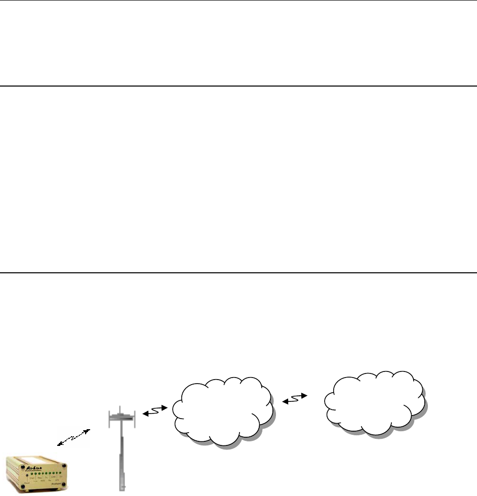
1.1 CDMA2000 1X
The AirLink CDMA modem provides data capability into the packet service offered
with CDMA2000 1X (1xRTT) technology. CDMA2000 1X offers higher speed data
operations than are available with IS-95 service. IS-95 is limited to 14.4 kbps. 1X
service uses a fundamental channel at 9600 bps and can add supplemental channels
when needed to boost speed to as high as 153.6 kbps on the downlink (network to
modem) and 76.8 kbps on the uplink (modem to network).
Internet
CDMA
1xRTT
Network
PinPoint CDMA User Guide Version 1.0
AirLink Communications, Inc. Page 2 February 22, 2003
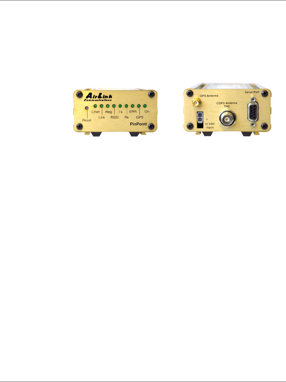
1.2 Product Overview
The AirLink PinPoint CDMA is a rugged, full duplex 1xRTT CDMA modem that
provides wireless transport capabilities for fixed and mobile applications. CDMA is
an efficient and secure wireless technology that works well for fixed or mobile
applications.
The PinPoint's rugged form factor is ideal for industrial and commercial applications
that require real-time communications. The PinPoint provides wireless data
communications for a variety of applications, such as fleet management, public
safety, ambulance, traffic control, home delivery, transit arrival systems and more.
Front of PinPoint 9612 Back of PinPoint 9612
PinPoint CDMA User Guide Version 1.0
AirLink Communications, Inc. Page 3 February 22, 2003
2 Network Connection
The AirLink PinPoint CDMA will be capable of offering multiple network connection
options. As of January 2003, the PinPoint CDMA will only use 1xRTT. Circuit
switched and SMS will follow later.
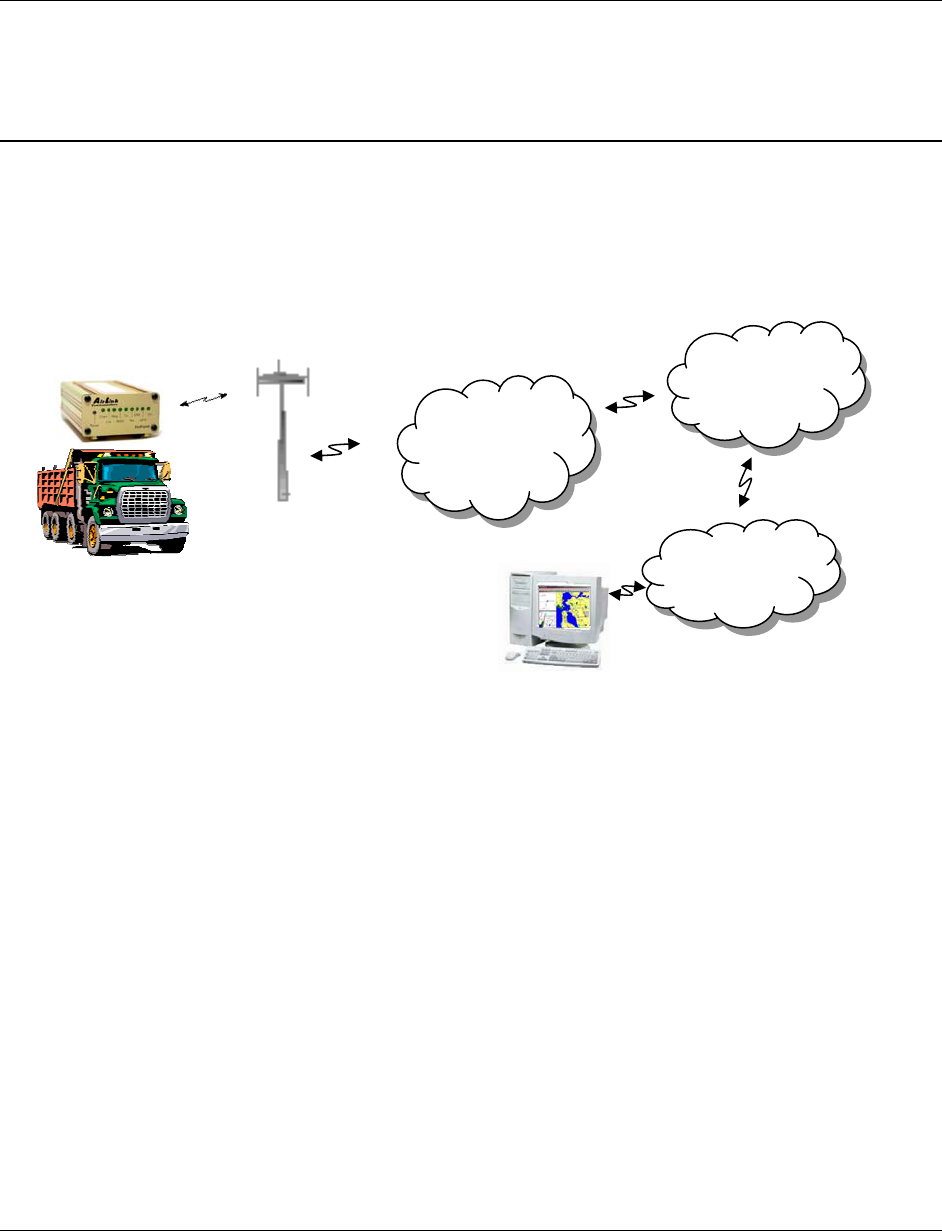
2.1 Internet (TCP/IP) Connections via 1xRTT
When using the PinPoint CDMA, remote access to is done via a PPP (TCP/IP)
connection to the CDMA network. The CDMA carrier actually provides Internet
connectivity, and, therefore, it becomes the ISP for that session. Applications such as
web browsing, email, FTP, etc should work as they would normally.
NOTE: Connections to Internet are provided by carrier.
Corporate network connections are unique and not provided as part of service.
CDMA
1xRTT
Network
Internet
Corporate
LAN
ATS
PinPoint CDMA User Guide Version 1.0
AirLink Communications, Inc. Page 4 February 22, 2003
3 Windows 2000 Setup for 1xRTT Communications
This section describes the setup of Windows to enable communications over the
CDMA 1xRTT network. Windows 2000 is used as the example because it the one
Windows OS revision that carries the most similarity to both Windows 98 as well as
WinXP.
3.1 Windows 2000 Modem Configuration
3.1.1 Prepare the Modem for Installation
• Connect the modem to the computer with the DB9 cable
• Plug in the AC adapter, connect the antenna(s) and power on the modem
• Obtain administrator privileges on your system.
If you do not know how, check with your system administrator
3.1.2 Adding the Modem
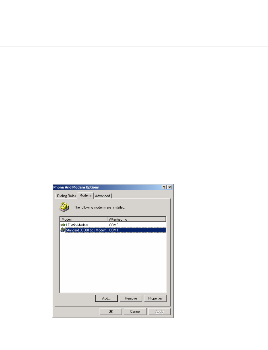
• Select Start> Settings> Control Pane> Phone and Modems Options
• You should see be in the Phone And Modem Options dialog box. Select the
Modems tab
• Select Add.
• Check "Don't detect my modem..." and select Next
• Select (Standard Modem Types) from the Manufacturers and then select
Standard 33600 bps Modem under "Models."
• Select Next
• Check Selected Ports, then select the COM port the modem is connected to and
select Next

PinPoint CDMA User Guide Version 1.0
AirLink Communications, Inc. Page 5 February 22, 2003
• Select Finish to exit the "Install New Modem" wizard
• You should see the modem added to the correct COM port
• To set the modem speed on the driver, highlight the modem driver and select
Properties.
• Ensure the "Maximum Port Speed" is set to 115200, which is the default value of
the PinPoint CDMA.
• Select OK to exit.
PinPoint CDMA User Guide Version 1.0
AirLink Communications, Inc. Page 6 February 22, 2003
3.2 Windows 2000 PPP Configuration
This section describes how to setup a Windows 2000 Professional Dial-up connection
using an AirLink PinPoint CDMA Modem. The connection uses PPP to communicate
to the modem and gain access the Internet.
Before you start, you need the following:
• Administrator privileges to the computer you are configuring or access granted
by an administrator on the network to add/remove devices to your computer.
• A 1xRTT user account, password, and access number (obtained from your CDMA
Service Provider).
• Windows COM Port and modem set up for a Standard 33600 Modem (See
previous sections)
• No other program is to be running that is using the serial (COM) port that your
modem is attached to.
Now that the modem has been added, the Dial-up connection must be created.
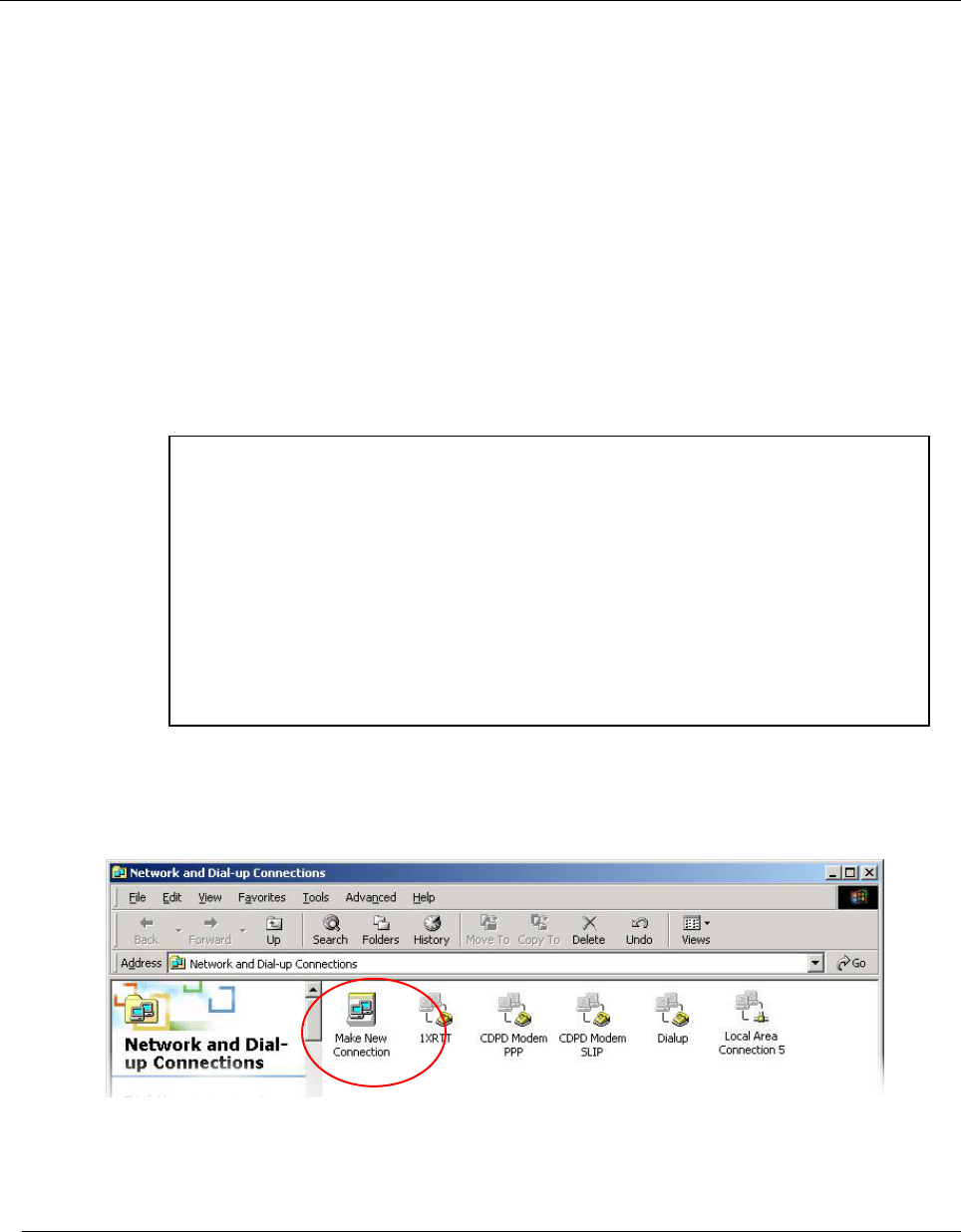
• Select Start> Settings> Control Pane> Network and Dial-Up Connections
• Double-click on “Make New Connection”.
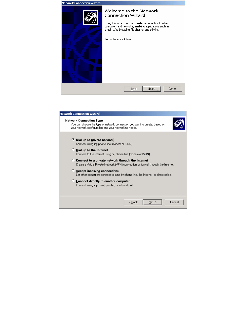
• When the Connection Wizard starts - select Next
NOTE: If you have an existing LAN connection, then this dial-up connection to
your CDMA modem may interfere with your existing connection. Once the
connection is initiated it will take over as the "default route" for the majority of
your LAN traffic, specifically Internet access. It's recommended to disconnect your
LAN connection before using a PPP connection with your AirLink modem.
If however you want the two connections to co-exist, you can de-select "Use
default gateway on remote network" (described later) and you can use the route
command to setup routing through the modem properly. Go to a Command
Prompt and type route /? to find out more, or talk to your administrator.
PinPoint CDMA User Guide Version 1.0
AirLink Communications, Inc. Page 7 February 22, 2003
Select Dial-up to Private Network
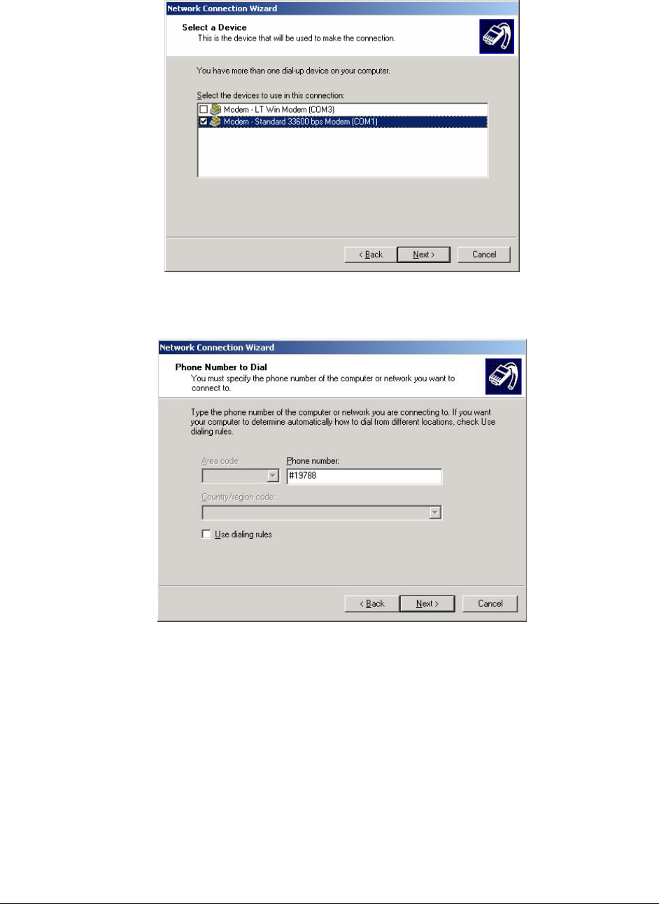
• If the modem is installed already, check the box next to “Modem – Standard
33600bps”
PinPoint CDMA User Guide Version 1.0
AirLink Communications, Inc. Page 8 February 22, 2003
• Select Next
• Enter the 1xRTT Access number (#19788)
• Select Next
• Select whether you want all users or just yourself to have access to this
connection.
• Select Next
• Enter 1xRTT for the name of the connection. If you want to add an icon for this
connection on the desktop, check “Add a shortcut to my desktop”
• Select Finish to exit the "Network Connection Wizard."
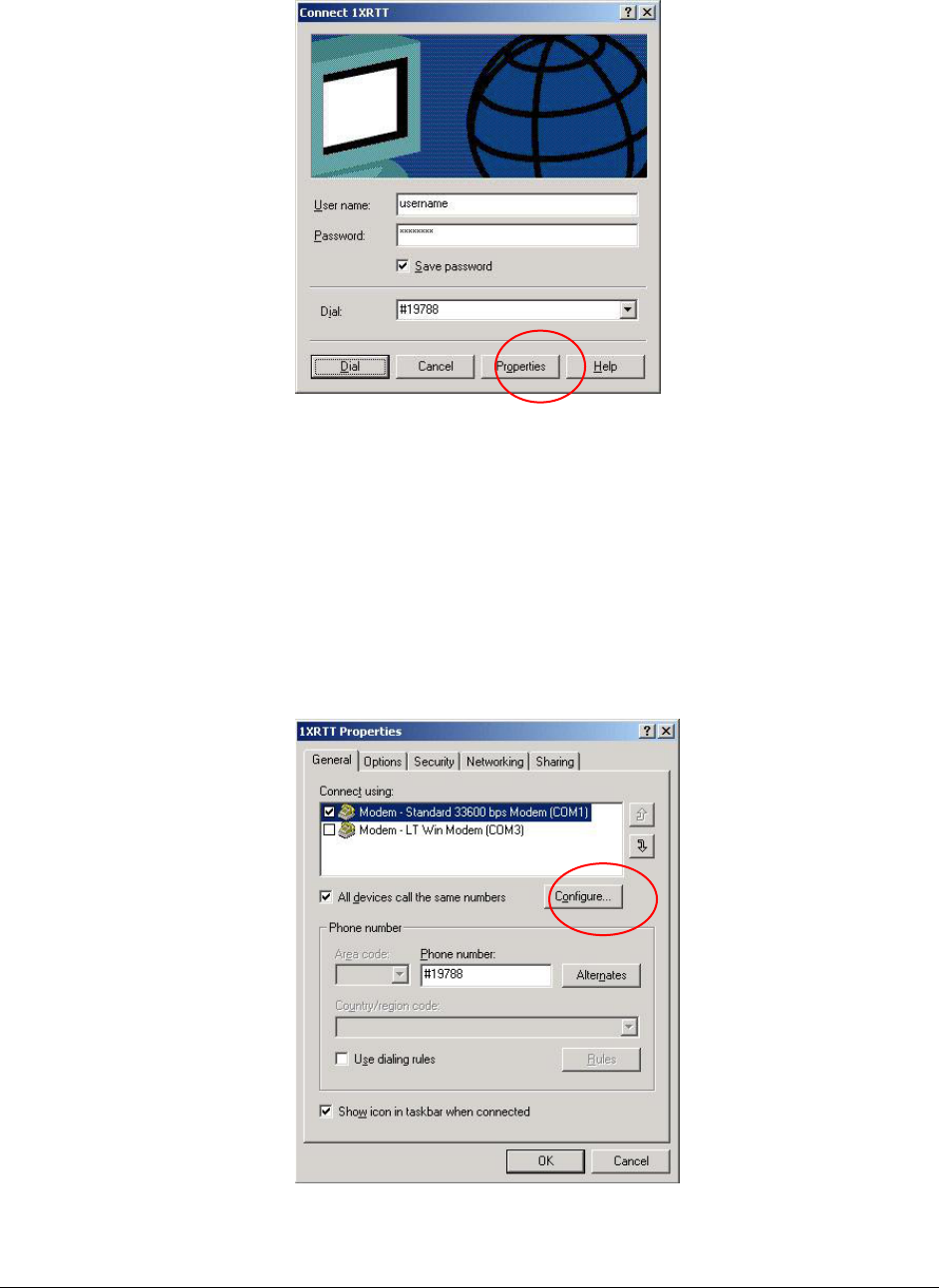
• The "Connect 1xRTT" dialog box should come up next.
• Enter the User name and Password provided by the CDMA Service Provider
• Select Properties
PinPoint CDMA User Guide Version 1.0
AirLink Communications, Inc. Page 9 February 22, 2003
You now need to change some settings so that you can browse websites, send and
receive email, etc.
• Examine the General Tab settings
• “Connect Using” should have a check next to “Modem – Standard 33600bps
Modem (COMx)”
• “Phone number” (The 1xRTT Access Number provided by the carrier)
• Uncheck "Use dialing rules" and check “Show icon in taskbar when
connected”
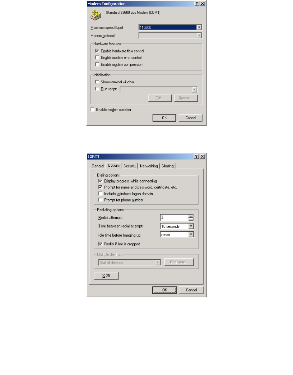
• Select the Configure button
• Maximum Speed: 115200
• Check Enable hardware flow control
PinPoint CDMA User Guide Version 1.0
AirLink Communications, Inc. Page 10 February 22, 2003
• Uncheck all other options
• Select OK
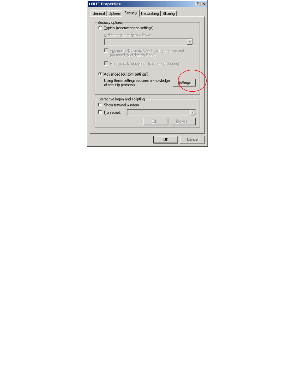
• Select Options tab
• Check or Uncheck options at your application requires.
• Set the Redialing options that will meet your needs.
Note: The options shown here should work for most applications.
Consult your Network Administrator for more help on connection options.
• Select Security tab
PinPoint CDMA User Guide Version 1.0
AirLink Communications, Inc. Page 11 February 22, 2003
• Select “Advanced (custom settings)”
PinPoint CDMA User Guide Version 1.0
AirLink Communications, Inc. Page 12 February 22, 2003
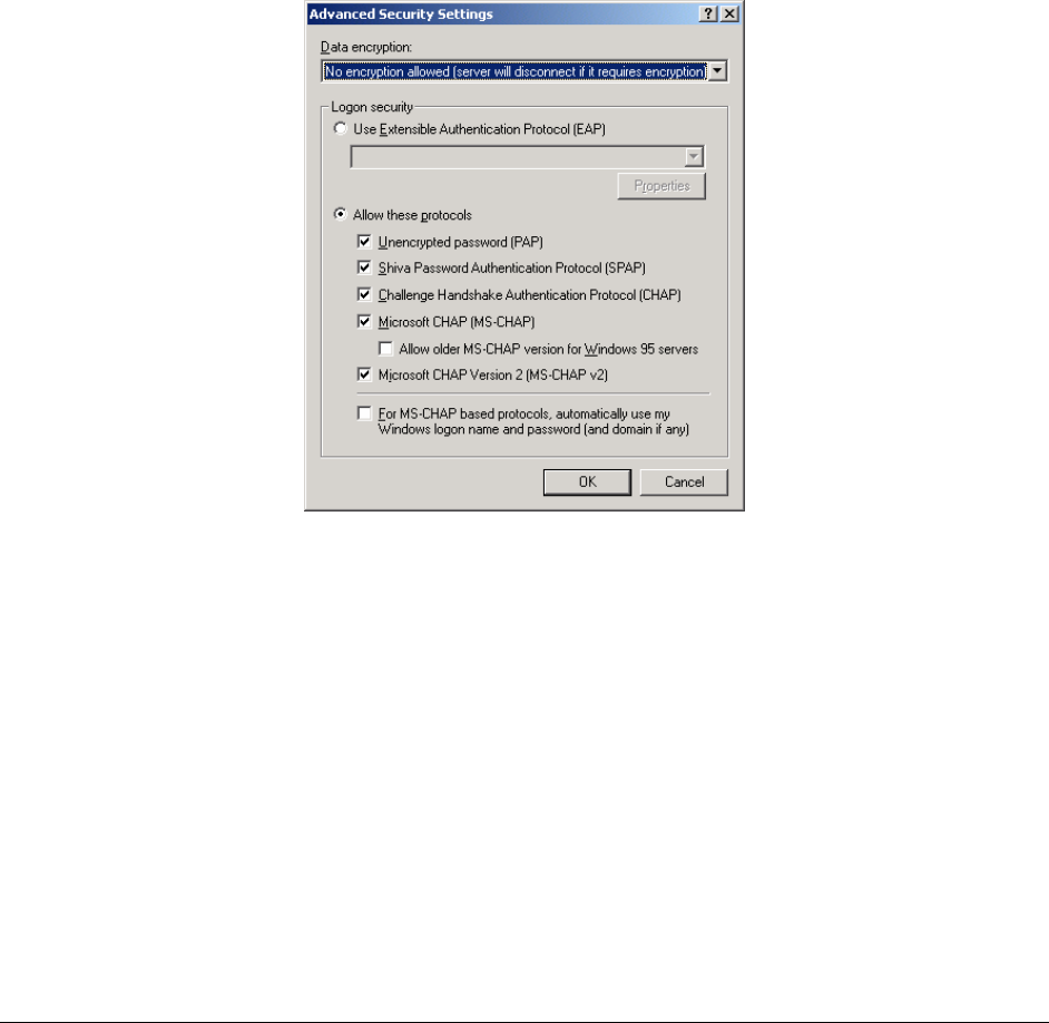
• Set Data encryption to "No encryption (server will disconnect if it requires
encryption)"
• For Logon Security check “Allow these protocols”
• Unencrypted password (PAP)
• Shiva Password Authentication Protocol (SPAP)
• Challenge Handshake Authentication Protocol (CHAP)
• Microsoft CHAP (MS-CHAP) (Do not check “Allow older MS-CHAP for W95
servers”)
• Microsoft CHAP Version 2 (MS-CHAP v2)
• Select OK
PinPoint CDMA User Guide Version 1.0
AirLink Communications, Inc. Page 13 February 22, 2003
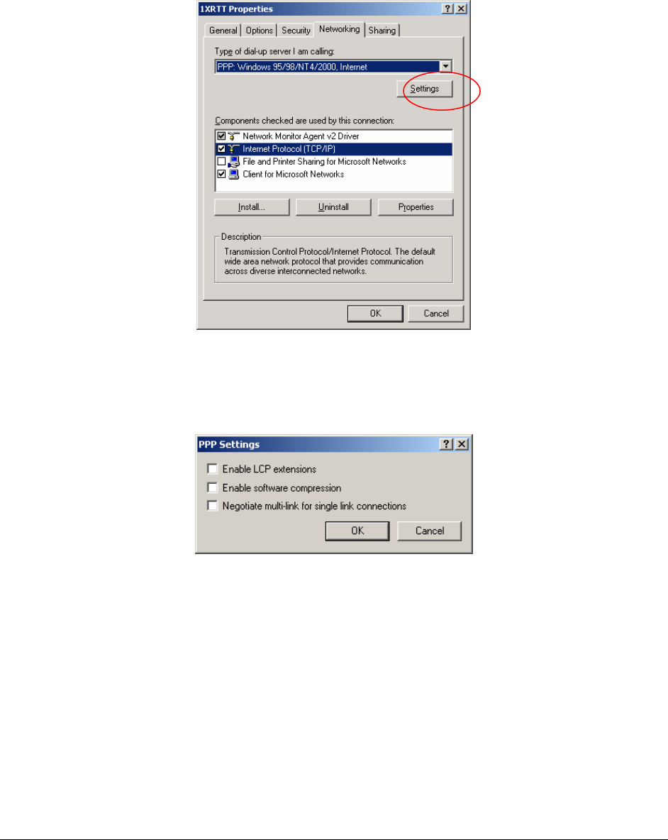
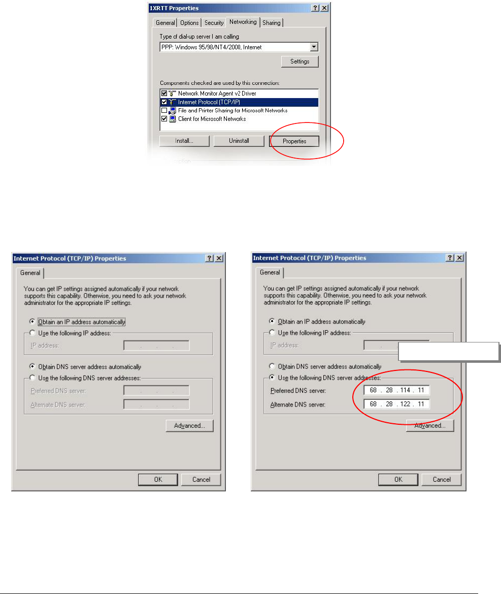
• Select Networking tab
• Type of dial-up server should show “PPP: Windows 95/98/NT 4/2000, Internet”
• Select Settings button
• Uncheck Enable LCP extensions, Enable Software Compression and
Negotiate multi-link for single link connections
• Select OK
PinPoint CDMA User Guide Version 1.0
AirLink Communications, Inc. Page 14 February 22, 2003
• In the Components section of the Networking tab, Internet Protocol (TCP/IP)
should be checked
• Select Internet Protocol (TCP/IP) and then select Properties
• "Obtain an IP address automatically" should be checked.
Normally, DNS server addresses are provided during PPP negotiations. If it is
necessary for you to enter DNS entries, check/enable "Use the following DNS server
addresses" and put in the proper addresses. (See your carrier or network admin for
details)
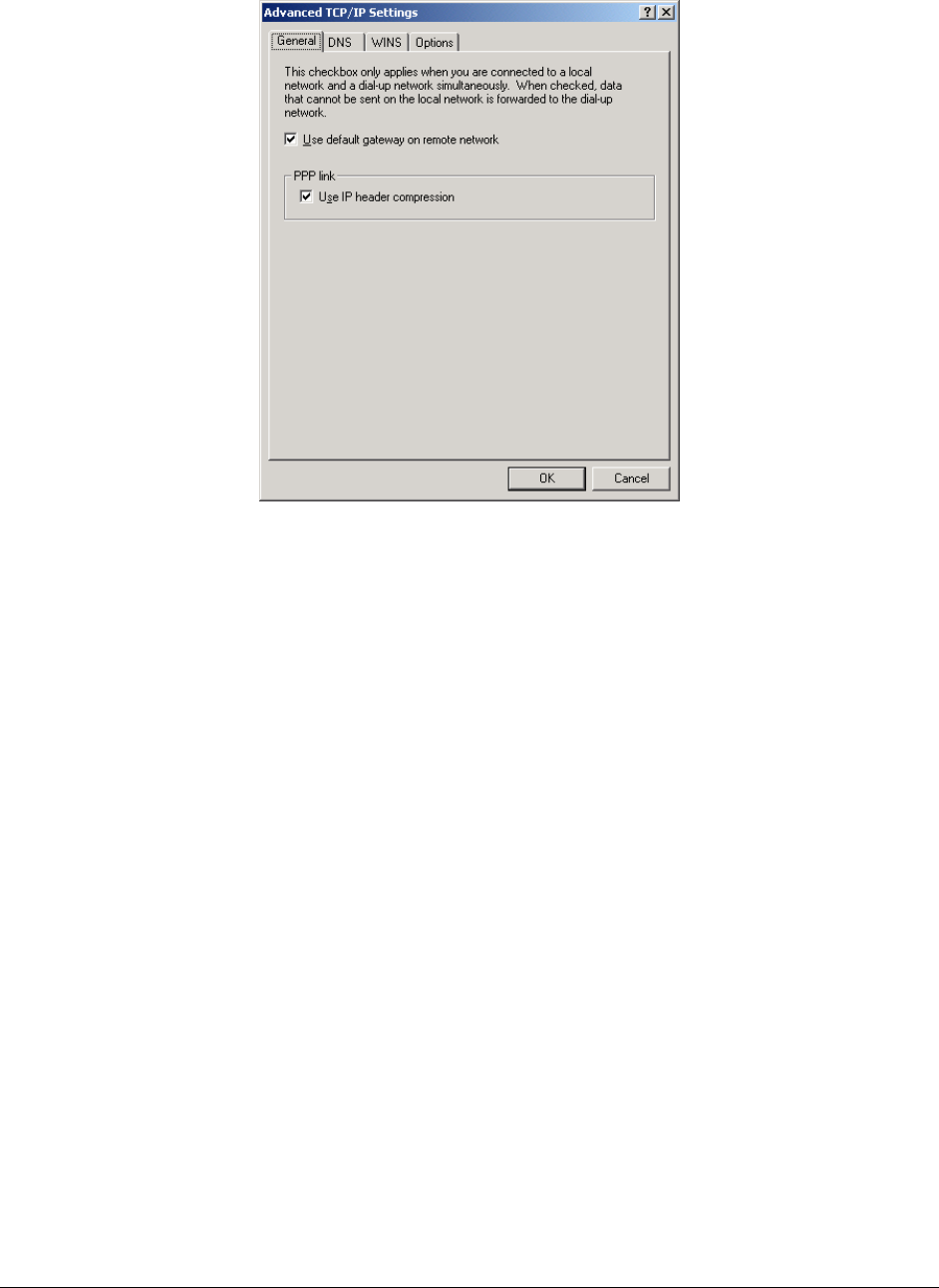
• Select the Advanced button
• Check Use default gateway on remote network and Use IP header
compression
Sprint DNS Servers
PinPoint CDMA User Guide Version 1.0
AirLink Communications, Inc. Page 15 February 22, 2003
• Select OK
• Leave the options in the Sharing tab unchecked
• Select OK
PinPoint CDMA User Guide Version 1.0
AirLink Communications, Inc. Page 16 February 22, 2003
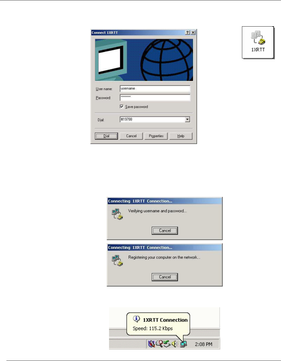
3.3 Making a 1xRTT Data Connection
This section shows what to expect when dialing a 1xRTT data connection.
• Go to Network and Dial-Up Connections and double-click on the 1xRTT icon
• Enter the user name and password provided by the carrier for the account.
• Click on DIAL. If you have enabled the connection progress display, you will see
the connection being made.
Once connected, you will see the connection status displayed in the bottom right
corner in the Task Bar.

PinPoint CDMA User Guide Version 1.0
AirLink Communications, Inc. Page 17 February 22, 2003
4 Low-power Mode
A PinPoint CDMA can be configured to enter a low power mode in order to conserve a
vehicle’s battery. The PinPoint can power down when the voltage to the modem drops
below a configured threshold (caused by the vehicle being turned off), or when DTR
changes (usually a contact or voltage controlled by the key switch, signaling when the
vehicle is turned off).
Note that when the PinPoint CDMA is in low power mode, neither the GPS module
nor the modem is powered. After a power cycle or reset, the low power controls are
ignored for 5 minutes in case the timers are short.
The options are set using AT commands.
VLTG
Voltage Power
Policy
This setting controls the low voltage threshold used to put
the PinPoint into low power mode. It is measured in tenths
of a volt. For example, if you want the modem to enter low
power mode when the input voltage falls below 13.0 volts,
this should be set to: 130
Recommended value: 130 (for 13.0 volts)
NOTE: Be VERY careful changing this setting. Ensure the
modem is close by when enabling this parameter, because it
may power down within 5 minutes.
PTMR
Powerdown Timer
This is the Power down timer. It specifies the length of time
in minutes after a DTR event or voltage drops below the
threshold, before the modem actually enters the low power
mode. If DTRP and VLTG are set to 0, this setting does
nothing.
Recommended value: 15 (for 15 minutes)
Note: There is always a minimum of 1 minute between a
power down event and actual shutdown (to give the modem
time to prepare), so entering '0' (zero) will not power down
the modem immediately, but after one minute.
DTRP
DTR Power Policy
This allows the modems power mode to be controlled by the
state of the DTR [Data Terminal Ready] signal.
0 = Ignore this feature.
1 = Low power when DTR is low.
2 = Low power when DTR is high.
PinPoint CDMA User Guide Version 1.0
AirLink Communications, Inc. Page 18 February 22, 2003
5 PinPoint Vehicle Installation
5.1 Overview
Installing a PinPoint in a vehicle consists of:
• Choosing a location in the vehicle for the PinPoint
• Mounting the PinPoint
• Hooking up power to the PinPoint
• Routing the cables through the vehicle
• Positioning the antennas for good reception
• Connecting and securing cables to the PinPoint
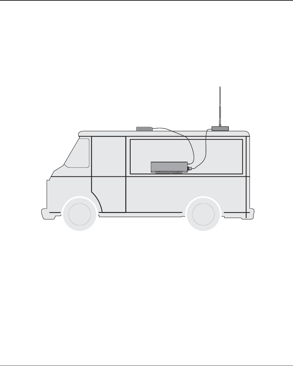
Note: Keep all cable lengths as short as possible during installation. Route
the cables in such a way so they are protected and will not cause
interference. Bundle and tie excess amounts if needed.
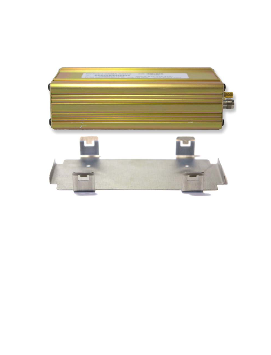
Modem Antenna
GPS Antenna
PinPoint
(not to scale)
PinPoint CDMA User Guide Version 1.0
AirLink Communications, Inc. Page 19 February 22, 2003
5.2 Mounting the PinPoint
First locate a place in the vehicle where the PinPoint will go. Make sure the PinPoint
will be away from direct exposure to the elements (sun, rain, etc.). Possible locations
are: in a trunk where luggage or other items won’t hit it, in the console, or behind the
seats in pickup trucks. Ensure the location is secure and will not put the PinPoint in
the way of anything.
1. Mount the PinPoint on the provided bracket.
2. Connect the PinPoint’s power cable to a fused 12 or 24 VDC power
source. (Note: PinPoint will draw less than 1/2 Amp at 12V.)
3. Mount the CDMA Antenna and route the cable to the PinPoint location.
Make sure any excess cable is tie-wrapped and not in the way of any
luggage, passengers, or anything else.
PinPoint CDMA User Guide Version 1.0
AirLink Communications, Inc. Page 20 February 22, 2003
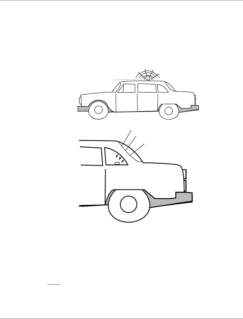
5.3 Installing the Antennas
There are three options for an antenna:
• magnetic roof-mount
• through glass-mount
• permanent mount
1. Mount the GPS Antenna in the vehicle. The less the cable is wrapped and
bound together, the better it will perform. Place it on the roof, or on the dash,
or rear panel where it has a good view of the sky (greater than a 90° angle
view of the sky -- see Figure 2).
GPS ANTENNA
Figure 2 – Optimum GPS antenna positioning on a vehicle
2. Connect the GPS Antenna into the PinPoint’s rear panel.
3. Connect the CDMA Cellular Antenna to the PinPoint’s TNC connector.
4. Plug in the power connector into the power receptacle on the PinPoint’s rear
panel.
Note: The green power light should be on at this point.

PinPoint CDMA User Guide Version 1.0
AirLink Communications, Inc. Page 21 February 22, 2003
6 Using AT Commands
This document is a reference for using AT commands with the AirLink PinPoint
CDMA modems.
Terminal Emulation - To communicate with the modem using AT commands, you
need to have an ASCII terminal emulation program running on a PC (default in
Windows is HyperTerminal). If you use HyperTerminal, set it to "Direct to COMx"
(where x is the COM port the modem is connected to by serial cable), instead of using
a specific modem driver like "Standard 33600 modem."
The terminal emulation program should be configured to operate at 115000 baud, 8
data bits, no parity, and one stop bit (115000, 8N1), and use Hardware Flow Control.
Power On - With the cable connected and the terminal emulation configured, power
the modem on. The ON LED should illuminate. On the terminal emulation screen,
you should see a some characters appear. Send the modem a generic AT command to
see if it is responding properly. (See next item for details).
Sample AT Commands
Here is an example of entering AT commands, changing some settings, saving and
resetting the modem. (Note that any command you are unsure of is explained in The AT
Commands section.)
Type AT and press Enter <enter>. AT<enter>
You should get a response of "0" or "OK".
To turn on echo and verbose modes, type the following: ATE1V1<enter>
You should see an "OK" response if Verbose Mode was properly activated (V1)
If you should see a “0” response, your modem is in Terse Mode and the V1 command did
not adhere.
Try ATV1 again by itself if that happens. You should see an “OK” response now.
To set the baud rate slower, (like 115200), type the following:
AT+IPR=115200,8N1<enter>
You should get an "OK" (if in Verbose Mode)
Note:
HyperTerm needs to be disconnected and reconnected after each baud rate change to
have it take effect.

PinPoint CDMA User Guide Version 1.0
AirLink Communications, Inc. Page 22 February 22, 2003
6.1 Terminology
In this section the following terminology is used:
Host: This is the computer or terminal that is attached to the serial port of
the PinPoint. Also known as the DTE.
Modem: The PinPoint CDMA. The DCE to the host.
OEM
Modem:
The embedded communications module, a Sierra SB555.
Server: A computer to which a PinPoint 9612 is communicating wirelessly.
6.2 PinPoint Serial Communication Modes
The PinPoint can be in one of six serial communication modes with the attached
Host:
AT: The modem accepts and responds to standard, Hayes-style AT
commands. This mode is the default.
PPP: Modem is using PPP to communicate with the Host.
PassThru: Direct connection to internal OEM Modem.
UDP PAD: Any data received on the serial port is assembled into UDP packets
and send to the connection’s associated IP and Port (described
later). Any responses received from the associated IP and port
destined for the modem’s Device Port are unwrapped and sent out
the serial port.
TCP PAD: Any data received on the serial port is packaged into TCP messages
and sent to the associated connection’s IP and Port (described
later). Any data received from the TCP peer is unwrapped and sent
out the serial port.
SLIP: Modem is using SLIP to communicate with the Host.
The default state is AT mode. If the modem is in any of the other modes, AT mode
can be re-entered by either deactivating DTR (if Ignore DTR, S211, is not set),
issuing the +++ escape sequence (if Disable AT Escape, DAE, is not set), or power
cycling the modem.
The modem can be programmed to enter one of the other modes automatically on
power up. This is done using the Startup Mode Default (MD) AT command. If
this setting is non-zero, the modem will enter the specified mode after 5 seconds. If
you want to cancel this behavior, the ATMD0 AT command can be used before the 5-
second timeout expires.
The modes are described in more detail in the following sections.

PinPoint CDMA User Guide Version 1.0
AirLink Communications, Inc. Page 23 February 22, 2003
6.2.1 AT Mode
AT commands are used to configure the modem, command it to do something, or
query a setting.
AT commands must always be terminated by <CR> (ASCII character 0x0D).
If E=1 (Echo On), the AT command (including the terminating <CR>) will be output
before any responses defined in the next section.
Response Framing
Two settings affect the format of AT command output: V (Verbose) and Q (Quiet).
If Q=1 (Quiet On), no result codes are output whatsoever, so there is no response
generated by a (non query) command. If Q=0 (Quiet Off), result codes are output.
The format of this output if then affected by the Verbose setting.
If Quiet mode is off, the result code is affected as follows: For V=1 (Verbose mode),
the textual result code is surrounded by <CR><LF> and any AT query response is also
surrounded by <CR><LF>; for V=0, (Terse mode), a numeric result code is output with
a single trailing <CR> (no <LF> is output), while any AT query response is followed
by <CR><LF> (there is no preceding output).
For example, possible output to the AT command “AT<CR>” (assuming quiet mode is
not on) is:
0<CR> - if V=0
<CR><LF>OK<CR><LF> - if V=1
6.2.2 PPP Mode
In PPP mode, the modem acts as a PPP server, providing an IP address, and DNS
servers (if available) to the Host.
PPP mode is entered be using the “AT\APPP” command. It can also be entered by
issuing a Dial TCP to 10.0.0.1 (e.g. ATDT10.0.0.1) or entering the “CLIENT”
command. At this point the modem assumes that the host will start PPP negotiation.
The IP received by the host in the resulting negotiation will either be a private (non-
routable) IP or a public (network-routable) IP provided by the OEM Modem’s
network, depending on the settings of S300. The value of this IP can be determined
beforehand by querying S110.
Using a private IP insulates the PPP client from changes in IP addresses of the
underlying network, as the AirLink modem will perform basic NAT-like address
translation on all packets. However, if a public IP address is being used, any changes
in the IP (as determined by the underlying communications network) will result in
the PPP link to the host being disconnected, requiring the host to reinitiate it.
The host can exit PPP mode by deactivating DTR (if S211=0) or issuing the +++ AT
escape sequence.
Note that DTR needs to be asserted (or S211=1) by the host before PPP mode can be
entered.

PinPoint CDMA User Guide Version 1.0
AirLink Communications, Inc. Page 24 February 22, 2003
6.2.3 PassThru Mode
In PassThru mode, all serial traffic is sent directly between the internal OEM
Modem and the host. In this mode, the AirLink modem does not behave normally.
This mode can be used to configure OEM Modem-specific settings (e.g., for
provisioning, etc.)
Issuing the “AT\APASSTHRU” enters this mode. The modem responds with CONNECT,
at which point a direct connection to the modem is established. Note that some OEM
Modems requires upwards of 20 seconds before AT commands can be entered, so be
patient if there seems to be no response to AT commands.
This mode can only be exited by power cycling the modem.
6.2.4 UDP PAD Mode
When the modem is in UDP PAD (Packet Assembly and Disassembly) Mode, all
characters received on the serial port are assembled into UDP packets and sent to
the mode’s remote IP address/port, and any packets received from the same IP/port-
destined for the modem’s Device Port (see *DPORT)--are disassembled and dumped
onto the serial line.
A UDP connection (there isn’t really a connection because UDP is connectionless) is
initiated by one of the following methods:
• Using the Dial UDP (DP) AT command (e.g., ATDP192.168.3.23/3456); or
• Setting the Startup Mode Default (MD) to 3 (UDP) so that UDP mode is entered
automatically when the modem powers up. All packets will be sent to the IP/port
specified in S53, and you must make sure that the default connect mode in S53 is
set to “P” (UDP).
• UDP auto answer is enabled (S82=2), an incoming UDP packet is received by an
IP address matching that in S53 and/or allow any IP is set (AIP=1), and the
modem is in AT mode or isn’t connected while in UDP or TCP modes.
UDP packet assembly is affected by the values of S50 (PAD Forwarding Timeout)
and S51 (PAD Forwarding Character). S50 specifies (in tenths of seconds) an
interval of time for which to collect characters before they are forwarded; S51 (if non-
zero) specifies the ASCII code of a character that needs to appear in the data before a
packet is sent.
The host can exit UDP mode by deactivating DTR (if S211=0) or issuing the +++ AT
escape sequence.
Note that DTR needs to be asserted (or S211=1) by the host before UDP mode can be
entered.
6.2.5 UDP Submodes
UDP PAD mode supports the submodes Modbus, Reliable UDP, and Multicast UDP.
UDP Auto Answer
UDP auto answer (S82=2) is equivalent to what was previously called UDP half-open
mode. When set, and in AT mode, it will automatically establish a UDP “connection”

PinPoint CDMA User Guide Version 1.0
AirLink Communications, Inc. Page 25 February 22, 2003
to the IP address (bound by the value S53 and/or AIP) from which a UDP packet was
received. This “connection” will be terminated once the UDP auto answer timeout
(S83) occurs, and the modem will return to AT mode. This behavior is identical to
that in the non-NGE modems.
UDP auto answer also now works when in UDP (MD3) and TCP (MD4) modes. If we
are in UDP mode, and we don’t have a current “connection”, a new “connection” will
be established with the IP address (bound by the value S53 and/or AIP) from which a
UDP packet is received. When the UDP auto answer timeout (S83) occurs, the
modem returns to a non-connected UDP mode, which allows a new “connection” to be
established. Any data that is received from the host port when there is no connection
will result in a “connection” being established with the address specified in S53, and
any data being forwarded to this address until the UDP auto answer timeout occurs.
If the connect to last UDP setting (*UDPLAST=1) is active, the address in S53 will
be changed to reflect the address of the last answered “connection” so that when new
data is received over the host port in a non-connected state, a “connection” will be re-
established with the last address. This behavior is the same as Hybrid2 (MD6) mode.
UDP auto answer in TCP (MD4) mode works the same as in UDP (MD3) mode,
except instead of returning to non-connected UDP mode when the UDP auto answer
timeout occurs, the modem returns to TCP mode.
6.2.6 TCP PAD Mode
TCP PAD (Packet Assembly and Disassembly) Mode is similar to UDP, except that a
real TCP connection is made to the remote IP/port.
A TCP connection is established by one of the following methods:
• Using the Dial TCP (DT) AT command (e.g., ATDT192.168.3.23/3456); or
• Setting the Startup Mode Default (MD) to 4 (TCP) so that TCP mode is entered
automatically when the modem powers up (assuming the remote computer
responds to the TCP connection request). All packets will be sent to the IP/port
specified in S53, and you must make sure that the default connect mode in S53 is
set to “T” (TCP).
• TCP auto answer is enabled (S0=1|2), a TCP connection request is received, and
the modem is in AT mode or isn’t connected while in UDP or TCP modes.
The value of S7 (TCP Connection Timeout) specifies the number of seconds to wait
for a successful TCP connection to be established. If a connection has not been
successfully established before the timeout occurs, ERROR/BUSY is returned. TCP
PAD mode is affected by S50 and S51, like UDP Mode. It is also affected by the
values in TCPT and TCPS (serial idle timeout for TCP connection before it’s
dropped)
The host can exit TCP mode by deactivating DTR (if S211=0) or issuing the +++ AT
escape sequence.
Note that DTR needs to be asserted (or S211=1) by the host before TCP mode can be
entered.

PinPoint CDMA User Guide Version 1.0
AirLink Communications, Inc. Page 26 February 22, 2003
6.2.7 TCP Auto Answer
TCP auto answer (S0=1|2) also allows a TCP connection to be “answered” when in
UDP mode with UDP auto answer on and there is no current UDP “connection”. This
functionality is the same as the answering of a TCP connection while in Hybrid
modes.
6.2.8 Hybrid Modes
The hybrid modes from the pre-ALEOS days (MD=5, 6) are no longer implemented as
special, unique modes. Now that UDP auto answer (UDP half-open, S82=2) can be
enabled in conjunction with UDP PAD mode (MD3), effectively this is the same as
MD5 and MD6 previously accomplished. Setting MD5 and MD6 are still supported,
but not recommended, since all they do is set several settings as described below.
The settings to accomplish hybrid modes:
AT Setting Hybrid (MD5) Hybrid2 (MD6)
MD 3 3
S82 2 2
S0 1 1
*UDPLAST 0 1
6.2.9 SLIP Mode
SLIP mode is entered be using the “AT\ASLIP” command. As in PPP Mode, the IP
address that the host assumes is affected by the setting of S300. SLIP does not
negotiate the IP with the host, so before making a SLIP connection, the host SLIP
driver must be configured to use the IP specified by querying S110.
The host can exit SLIP mode by deactivating DTR (if S211=0) or issuing the +++ AT
escape sequence.
Note that DTR needs to be asserted (or S211=1) by the host before SLIP mode can be
entered.

PinPoint CDMA User Guide Version 1.0
AirLink Communications, Inc. Page 27 February 22, 2003
6.3 AT Command Reference
Command Description Effective
+++ AT Escape sequence (not preceded by AT).
If modem is in a mode other than AT, this
sequence causes the modem to re-enter AT mode.
There must be 1 second of idle time on the serial
port before and after the sequence. Note that the
“+” is ASCII character 0x2B.
NOTE: The detection of this sequence is disabled if
DAE=1
Immediately
A/ Re-execute last command. Immediately
AIP=n [?] n = 0: Allow only the IP specified in S53 to connect
when UDP auto answer is enabled (S82=1).
n = 1: Allow any incoming IP to connect when UDP
auto answer is enabled (S82=1).
Still subject to any Friends filters that may be
defined

PinPoint CDMA User Guide Version 1.0
AirLink Communications, Inc. Page 28 February 22, 2003
Command Description Effective
D[method][d.d.d.d][/ppppp] Dial a connection to a remote IP and Port using
either UDP, TCP, or Telnet.
method =
P – Establish a UDP connection
T – Establish a TCP connection
N – Establish a Telnet connection
d.d.d.d = IP address to establish connection to
ppppp = IP port to establish connection to
Examples:
ATD – Dial (establish) default connection per
S53
ATDPnnn.nnn.nnn.nnn[/ppppp] - Dial
(establish) UDP connection to the specified
IP address/port.
If the method, IP address, or port is omitted, the
values from S53 are used. If a telnet connection is
requested (N) and the port is not supplied, port 23
will be used instead of the value from S53.
To end the connection, issue the +++ escape
sequence or drop the DTR line (if Ignore DTR
S211=0)
NOTE: The source port of the connection is the
Device Port (set by S110 or *DPORT)
Immediately
DAE=n [?] Disable AT Escape Sequence detection
n = 0: Enable +++ AT escape sequence detection.
n = 1: Disable +++ AT escape sequence detection.
DTRP=n [?] Set or query the DTR power policy.
n = 0: Ignore DTR for power control
n = 1: Low power mode when DTR is low
n = 2: Low power mode when DTR is high
En Toggle AT command echo mode.
n = 0: Echo Off
n = 1: Echo On.
Immediately
FM=n [?] Friends Mode – Only allow specified IPs to access
the modem
n = 0: Disable Friends mode
n = 1: Enable Friends mode – Only friends can
contact us (see below); packets from other IP
addresses are ignored.
Immediately

PinPoint CDMA User Guide Version 1.0
AirLink Communications, Inc. Page 29 February 22, 2003
Command Description Effective
Fn=d.d.d.d [?] Friends mode IP address
n = Friends list index [1 – 10]
d.d.d.d = IP address to be allowed to access the
modem
255 = allow any number 0-255
Example: 166.129.2.255 allows access by all IPs in
the range 166.129.2.0—166.129.2.255.
Immediately
H This command does nothing but does not cause an
error either.
Immediately
HOR=n [?] Half-Open Response – In UDP auto answer (half-
open) mode:
n = 0: No response codes when UDP session is
initiated
n = 1: RING CONNECT response codes sent out
serial link before the data from the first UDP
packet.
Note: Quiet Mode must be Off.
I[0] Returns the product name. Immediately
I1 Returns AirLink modem’s firmware version,
hardware ID, and copyright.
Immediately
I2 Returns the OEM Modem’s firmware version and
relevant hardware ID
Immediately
I3 Returns the OEM Modem’s unique ID Immediately
M This command does nothing but does not cause an
error either.
Immediately
MDhh [?] Set or query the modem's default power-up mode
hh (hex byte) =
00 – normal (AT command) mode
01 – SLIP mode
02 – PPP mode
03 – UDP mode (address/port is in S53)
04 – TCP mode (address/port is in S53)
When the modem is power-cycled, it enters the
mode specified by this command, after 5 seconds. If
the mode is 1 or 3, on startup, typing ATMD0
within (about) 5 seconds changes the mode to
normal. Otherwise, it enters SLIP or UDP mode
and no longer responds to AT commands.
5 seconds
OPRG=n [?] Enables/disables over-the-air programming of the
modem.
n = 0: Disables over-the-air programming.
n = 1: Enables over-the-air programming.
Immediately

PinPoint CDMA User Guide Version 1.0
AirLink Communications, Inc. Page 30 February 22, 2003
Command Description Effective
PINGd.d.d.d[,n] Ping the specified IP address. Sends a single ping,
returns either OK or ERROR depending on result.
Times out in 10 seconds. If n is provided, it
specifies the amount of data to send with the ping.
If n is not provided, the default, 50 bytes is used.
Immediately
PTMR=n [?] Number of minutes after one of the allowed
powerdown events (VTLG or DTRP) happens until
we actually powerdown. If DTRP and VLTG are
both zero, this setting means nothing.
NOTE 1: There is always a minimum of 1 minute
between powerdown event and actual shutdown (to
give the modem time to prepare); entering zero
will not powerdown the modem immediately, but
after one minute.
NOTE 2: In the first 5 minutes after modem
powers up for the first time, powerdown events are
ignored--this is to give the user a window where
bad configurations can be fixed.
Immediately
Qn [?] Set or query the AT quiet-mode setting.
n = 0: Off (Default)
n = 1: Quiet-mode on.
Immediately
S0=n [?] This register determines how a modem responds to
an incoming TCP connection request. The modem
remains in AT Command mode until a connection
request is received. DTR must be asserted or
Ignore DTR must be set for a successful TCP
connection
The modem will send a “RING” string to the host.
A “CONNECT” sent to the host indicates
acknowledgement of the connection [ACK].
n = 0: Off (Default)
n = 1: On
n = 2: Use Telnet server mode on TCP connections
Immediately
S7=n [?] Specifies the number of seconds to wait for a TCP
connection to be established when dialing out.
S23=<speed>,<databits>
<parity><stop bits> [?]
Query or set serial line parameters:
<speed> = [1200 | 2400 | 4800 | 9600 | 19200
| 38400 | 57600 | 115200 | 230400]
<databits> = [7 | 8]
<parity> = [O=Odd| E=Even | N=None |
M=Mark]
<stopbits> = [1|1.5|2]
Example: ATS23=19200,8N1 (sets modem to
19200, etc.)
NOTE: MUST be 8 data bits for PPP mode. The
settings take affect after reset.
Reset

PinPoint CDMA User Guide Version 1.0
AirLink Communications, Inc. Page 31 February 22, 2003
Command Description Effective
S50=n [?] Set or query data forwarding idle timeout. n =
tenths of seconds. (Used in UDP or TCP mode)
S51=n [?] Set or query PAD data forwarding character.
n = 0: no forwarding character
n = other: ASCII code of character that causes data
to be forwarded.
(Only for UDP or TCP mode.)
S53=[method]d.d.d.d[/ppppp]
[?]
Set or query Destination IP address, port, and
method. These are used as defaults for the D
(Dial) AT command.
method =
P – UDP
T – TCP
N – Telnet
d.d.d.d = IP address
ppppp = the port address
Immediately
S60=n [?] Telnet Echo Mode [n = 0–2]
n = 0: No Echo
n = 1: Local Echo (Default)
n = 2: Remote Echo
S82=n [?] Enables UDP auto answer (half-open) mode.
n = 0: Normal mode
n = 2: Enable UDP auto answer mode.
S83=n [?] Set or query UDP auto answer idle timeout. If no
data is sent or received before the timeout occurs,
the current UDP “connection” will be terminated,
allowing other IPs to “connect”. While “connected”
packets from other IPs will be discarded (unless
*UALL is set).
n = 0: No idle timeout (Default).
n = 1-255: Timeout in seconds.
S110=d.d.d.d[/ppppp] [?] Query IP address and port, or simply sets the
modem’s Device Port.
Since the IP address is determined from the
1xRTT network, any specified address will be
ignored. This command can be used to determine
the resulting IP address that will get negotiated if
a PPP connection is to be established.
d.d.d.d = IP address
ppppp = port number
NOTE: See also *DPORT
Immediately

PinPoint CDMA User Guide Version 1.0
AirLink Communications, Inc. Page 32 February 22, 2003
Command Description Effective
S211=n [?] Ignore DTR. For applications or situations where
hardware control of the modem is not possible, the
modem can be configured to ignore DTR. When
Ignore DTR is enabled, the modem operates as if
the DTR signal is always asserted.
n=0 [default]: Use hardware DTR.
n=1: Ignore DTR.
n=3: Ignore DTR and assert DSR. This value is
deprecated, and it recommended to use &S to
control the DSR instead. When this value is set to
3, &S will automatically be set to 0.
DTR –
Immediately
DSR – Mode
or network
coverage
change.
S221=n [?] Connect Delay [n = 0 – 255]
n = number of seconds to delay the “CONNECT’
response upon establishing a TCP connection
OR
n = number of tenths of seconds to delay
outputting ENQ on the serial port after the
CONNECT when the ENQ feature is enabled [see
*ENQ]
Immediately
S300=n [?] Set or query whether a private or public (network)
IP is to be used when the Host initiates a PPP
connection to the modem.
n = 0 [default]: Public (network) IP Mode: When
the Host initiates a PPP connection, the host will
be given the public IP that was obtained from the
OEM Modem. If the network issues a new IP, the
PPP connection will be closed (since the IP has
changed) and has to be re-initiated.
n = 1: Private IP Mode: When the Host initiates a
PPP connection, the host will be given the IP
address specified in S301. The modem will then
perform NAT-like address translation, which
shields the Host from network IP changes.
S301=d.d.d.d [?] Set or query the private IP address that is to be
negotiated by the PPP connection if S300=1.
S302=d.d.d.d [?] Set or query the IP address that can be used to
directly contact the modem once a PPP connection
is established. If this value is not specified,
192.168.13.31 will be used.
NOTE: This is not normally used nor needed by
user applications.
TCPS=n [?] TCP connection timeout (TCPT) units.
n = 0: TCPT specifies minutes.
n = 1: TCPT specifies seconds.

PinPoint CDMA User Guide Version 1.0
AirLink Communications, Inc. Page 33 February 22, 2003
Command Description Effective
TCPT=n [?] TCP connection timeout. Specifies a time interval
upon which if there is no in or outbound traffic
through a TCP connection, the connection will be
terminated. This value only affects the TCP
connection in TCP PAD mode.
n = minutes (if TCPS=0) or seconds (if TCPS=1)
Vn [?] Set or query Command Response Mode.
n = 0: Terse (numeric) command responses
n = 1: Verbose command responses (Default).
Immediately
VLTG=n [?] Set or query the voltage power policy.
n = 0: Ignore voltage for power control
n = low power voltage threshold in tenths of volts.
Example: ATVLTG=126 would power down the
modem if the voltage goes below 12.6V.
Xn [?] Extended Call Progress Result mode.
n = 0: turn off extended result codes (Default)
n = 1: turn on result codes only if S210=1. This
adds the text 19200 to the CONNECT response.
Immediately
Z Reset the modem.
NOTE: This command does nothing if *DATZ=1.
Immediately
&Cn [?] Set DCD mode. Currently DCD mirrors the DSR,
so any attempt to set this feature will be ignored.
Querying it will simply return the value for &S,
since DCD is mirroring DSR.
n = 0: Always assert DSR
n = 1: Assert DCD when in a data mode (UDP,
TCP, PPP, or SLIP) (Default).
n = 2: Assert DCD when the modem has network
coverage.
Mode or
network
coverage
change
&Dn [?] Set DTR mode.
n = 0: Ignore DTR (same as S211=1)
n = 2: Use hardware DTR (same as S211=0)
S211 can also be used to query.
Reset
&L<speed>,<databits>
<parity><stop bits>
Set serial line parameters:
<speed> = [1200 | 2400 | 4800 | 9600 | 19200
| 38400 | 57600 | 115200 | 230400]
<databits> = [7 | 8]
<parity> = [O=Odd| E=Even | N=None |
M=Mark]
<stopbits> = [1|1.5|2]
Example: AT&L19200,8N1 (sets modem to 19200,
etc.)
NOTE: MUST be 8 databits for PPP mode
Reset

PinPoint CDMA User Guide Version 1.0
AirLink Communications, Inc. Page 34 February 22, 2003
Command Description Effective
&Sn [?] Set DSR mode.
n = 0: Always assert DSR
n = 1: Assert DSR when in a data mode (UDP,
TCP, PPP, or SLIP) (Default).
n = 2: Assert DSR when the modem has network
coverage.
Note: Although deprecated, S211 can also be used
to request that DSR is always asserted. If S211 is
set to 3 and &S is changed to a non-zero value,
S211 will be changed to 1.
Mode or
network
coverage
change
&V View active profile (the contents of the registers) Immediately
&W Writes all changed modem settings. If this
command is not issued, any modified values will
revert back to their previous values at modem
reset.
Immediately
&Z This command does nothing but does not cause an
error either.
Immediately
\ACEPW=new123 Change the Ace password to a new value.
Password is case sensitive. Default value is 12345
Example: AT\ACEPW=new123
Immediately
\APASSTHRU Set modem operation to pass through mode. This
will pass any characters received on the serial port
directly to the internal OEM Modem and output
any characters from the internal OEM Modem out
the serial port. This allows direct
access/configuration of the OEM Modem. Once this
mode is entered, the unit must be physically reset
to return to normal operation.
NOTE: It may take some time for the OEM Modem
to respond after CONNECT is output. In addition,
this mode is not available through the remote AT
telnet server.
Immediately
\APPP Set modem operation to PPP mode. The modem
expects the Host to start PPP negotiation.
Immediately
\ASLIP Set modem operation to SLIP mode. Immediately
\Qn [?] Set or query the serial port flow control setting.
n = 0: No flow control is being used
n = 2: RTS/CTS hardware flow control is being
used
n = 4: Transparent software flow control. Uses
escaped XON and XOFF for flow control. XON
and XOFF characters in data stream are escaped
with the @ character (0x40). @ in data is sent as
@@.
Reset

PinPoint CDMA User Guide Version 1.0
AirLink Communications, Inc. Page 35 February 22, 2003
Command Description Effective
*CTSE=n [?] Clear To Send Enable
n = 0: Disabled (Default).
n = 1: Enable assertion of CTS.
This feature asserts CTS when there is no network
connection.
Note: Flow control (AT\Q) will override this
indication, so if you want to use CTS to indicate no
network coverage, flow control has to be off
(AT\Q0).
RS232 voltage levels: Positive = Network coverage,
Negative = no coverage.
Immediately
(if flow
control off)
*DATE=[mm/dd/yyyy],[hh:m
m:ss] [?]
Sets and queries the clock in the unit. Either the
date and time can be specified, or simply one of the
two can be specified in which case the unspecified
value will remain unchanged. The date and time
are always specified in UTC (Universally
Coordinated Time) and, as such, the hours are
specified in 24-hours format.
Note that if the product has a GPS (i.e. PinPoints),
the GPS will be used to set the time, in which case
any date/time specified will be ignored.
Immediately
*DATZ=n [?] n = 0: Normal Reset (Default).
n = 1: Disable Reset on ATZ.
Immediately
*DNSn=d.d.d.d Sets the DNS addresses to be returned during PPP
negotiation. If the underlying communications
network provides DNS addresses, they replace
those specified by this command. *DNS1 and
*DNS2 are valid.
*DPORT=n [?] Sets or queries the modem’s Device Port. Valid
values are 0-65535.
Immediately
*DU=n [?] Dial UDP Always – Whether the dial command
always uses UDP.
n = 0: dial a normal connection [default]
n = 1: dial UDP always, even when using ATDT
NOTE: When this parameter is set you cannot
establish a TCP PAD connection.
Immediately
*ENQ=n [?] Outputs an ENQ [0x05] after the TCP CONNECT
delayed by the Delay Connect Response time
[S221].
n = 0: Disabled (Default).
n = 1: Enables ENQ on CONNECT.
*NETCHAN? Returns the current active channel number.

PinPoint CDMA User Guide Version 1.0
AirLink Communications, Inc. Page 36 February 22, 2003
Command Description Effective
*NETIP? Query the current public (network) IP address of
the modem. This is the IP address that was
obtained from the embedded OEM Modem, and is
the address to which packets can be sent in order
to contact the modem from the Internet.
NOTE: This could be 0.0.0.0 if there is no current
network IP
*NETPHONE? Query the device’s phone number, if applicable.
*NETPW=pw [?] The password that is needed to login to the remote
network, if necessary.
*NETRSSI? Returns the current RSSI of the modem as a
negative dBm value.
*NETSTATE? Query the current network state. Will get one of
the following strings:
• Connecting To Network
The modem is in the process of trying to
connect to the network;
• Network Authentication Fail
Authentication to the network has failed.
Either *NETUID and *NETPW need to be
updated, or for some reason the network
refuses to allow the modem to connect;
• Network Negotiation Fail
Network connection negotiation failed. This
is usually temporary and often clears up
during a subsequent attempt;
• Network Ready
Modem is connected to the network and ready
to send data;
• Network Dormant
Modem is connected to the network, but the
link is dormant. It will be woken up when
data is sent;
• No Service
There is no network service (e.g., no CDPD,
or no 1xRTT);
• Hardware Reset
The OEM modem is being reset. This is
temporary.
*NETUID=uid [?] The login that is needed to login to the remote
network, if necessary.

PinPoint CDMA User Guide Version 1.0
AirLink Communications, Inc. Page 37 February 22, 2003
Command Description Effective
*TPORT=ppppp [?] Sets or queries the port used for the AT Telnet
server. Valid values are 0-65535. If 0 is specified,
the AT Telnet server will be disabled. The default
value is 2332.
Reset
*UALL=n [?] Accepts UDP data from any IP address when a
UDP “connection” is active. If there currently is
not a UDP “connection”, the data will be discarded
unless UDP auto answer is enabled and the IP
matches S53 or AIP is set.
n = 0: Only accept UDP data from the currently
“connected” IP address (Default).
n = 1: Accept UDP data from all IP addresses
when “connected”.
*UDPLAST=n [?] If enabled, sets S53 to the last accepted IP address
through UDP auto answer. This can be used in
conjunction with MD3 so that when there is no
“connection”, new host data will cause a connection
to be restored to the last IP accepted through UDP
auto answer.
n = 0: Do not remember the last accepted IP
through UDP auto answer. (Default).
n = 1: Set S53 to the last accepted IP.
*USD=n [?] Delays a received UDP packet by a specified
interval before sending it out to the serial port.
n = 0: No UDP packet delay (Default).
n = 1-255: Delay in 100ms units, from 100 ms to
25.5 sec.

PinPoint CDMA User Guide Version 1.0
AirLink Communications, Inc. Page 38 February 22, 2003
6.3.1 PinPoint Specific AT Commands
The AT commands in this Section are specific to the AirLink PinPoint.
Command Description Effective
*DEVICEID=n [?] Sets or queries the 64-bit Device ID that is used by the
PinPoint to identify itself to the server. The default is a
value that depends on the underlying communications
technology being used.
*DEVICEIDX=n [?] Same as *DEVICEID except entry of the 64-bit Device
ID is in hexadecimal.
*PPDEVID=0|1 [?] Whether or not the PinPoint should include the 64-bit
device ID in its GPS reports. Valid values are 0 or 1.
*PPIP=ipAddr [?]
or ATSIP=ipAddr [?]
PinPoint Server IP Address = IP address where GPS
reports are sent.
Example: ATSIP=192.100.100.100
NOTE: Also see ATSP
Immediately
*PPDIST=n [?]
or ATSD=n [?]
GPS Report Distance Interval in 100 Meter Units
Range n = 1-65535, 0 = Disabled
Immediately
*PPPORT=n [?]
or ATSP=n [?]
Port where GPS reports are sent. Possible value: nnnnn =
0 – 65535
NOTE: Also see ATSIP.
Immediately
*PPTIME=n [?]
or ATST=n [?]
or #TU=n [?]
GPS Report Time Interval Range n = 1 – 65535
Seconds, 0 = Disabled
NOTE: Also see TSV
Immediately
*PPTSV=n [?]
TSV=n [?]
Timer for Stationary Vehicles.
n = [0--255]: Time interval in minutes that the PinPoint
will send in reports when it is stationary.
For example, if ATST=10, the PinPoint will send in reports
at least every 10 secs while it is moving; however, while it
is stopped, it will slow the reports down to this TSV value.
A zero value disables TSV.
Immediately
*GPSR=n [?] GPS report type. See RAP
*ODOM=0|1 [?] Whether or not odometer reporting is turned on
GPSn Send NMEA GPS strings out serial link.
ATGPS will cause the NMEA GGA, RMC, and VTG
GPS strings to output to the serial port one time.
ATGPS1 will cause these strings to be sent out the
serial link once per second forever.
ATGPS0 will stop the feed.
Immediately
SNF=n [?] Set or query “Store and Forward” of GPS reports
n = 0: Disable Store and Forward
n = 1: Enable Store and Forward (default)
Immediately

PinPoint CDMA User Guide Version 1.0
AirLink Communications, Inc. Page 39 February 22, 2003
Command Description Effective
Store and Forward will cause GPS reports to be stored up
if the PinPoint goes out of CDPD coverage. Once the
vehicle is in coverage the GPS reports will be sent en
masse to the server.
*SNFB=n [?] Store and Forward Behavior. See RAP.
*SNFM=n [?] Store and Forward Min Reports. See RAP.
*SNFR=0|1 [?] Whether or not Store and Forward reliability is enabled
#IG=n [?] Set or query GPS initialization timer. n = seconds.
Time in seconds to wait for GPS acquisition before
transmitting at high rates.
#U Immediately issue GPS report to programmed server IP
and port

PinPoint CDMA User Guide Version 1.0
AirLink Communications, Inc. Page 40 February 22, 2003
7 Technical Specifications
7.1 Quick Look:
• Support for CDMA2000 1X today
• Coming: Support for IS-95 Circuit Switched CDMA and SMS
• Dual-band support for both 800 MHz cellular and 1.9 GHz PCS bands
• Rugged aluminum case
7.2 Physical Characteristics:
• Weight: < 2 lb.
• Size: 3.3” wide x 2” high x 6.8" long
• RF Antenna Connector: 50 Ohm TNC
• Serial Interface: RS232 DB-9F
7.3 Power Specifications:
• Advanced Power Management features
• Input Voltage: 10 VDC to 28 VDC
• Input Current: 20 mA to 350 mA
• Typical Transmit/Receive: 300ma at 12VDC
• Dormant connection [idle for 10-20 seconds] 150 ma at 12 VDC
• Low power mode: 20 mA at 12 VDC
7.4 Environmental:
• Operating ranges: -30°C to +75°C*
• (<10%duty cycle limit above 60 °C)
• Humidity: 5%-95%Non-condensing
A thermistor inside the modem (monitored by the modem CPU firmware) causes flow
control to be activated should the internal temperature reach 75ºC (167ºF) as
measured at the radio. Flow control is released when the temperature falls below 75.
Should the temperature of the radio reach 80ºC (176ºF), the modem terminates the
connection in order to protect components and avoid drifting outside radio
specifications.

PinPoint CDMA User Guide Version 1.0
AirLink Communications, Inc. Page 41 February 22, 2003
7.5 Status LED Display:
• Channel [Chan] LED
Flashing = Searching for a channel
On = Found a channel
• Link LED
Off = No 1x or CDMA service
On = 1x or CDMA service is available on this channel
• Registration (REG) LED:
Off = No PPP link
On = PPP link is established and have an IP address.
• Transmit (TX) LED:
Off = Not transmitting
On = Transmitting (on RF)
• Receive (RX) LED:
Off = No incoming data
On = Receive data (on host)
• GPS LED
Off = No GPS fix
On = Have GPS fix
• Power (PWR):
Off = Power off
On = Power on
7.6 RF Features:
• 224 mW RF output (+23.5 dBm)
• Full duplex transceiver
• Dual-band support for both 800 MHz cellular and 1.9 GHz PCS bands
• Data rates up to 153.6 kbps (forward channel) and 76.8 kbps (reverse channel)
7.7 Application Interface Features:
• RS232, 1200 bps to 115.2 kbps
• AT Commands, PPP, SLIP, UDP, TCP

PinPoint CDMA User Guide Version 1.0
AirLink Communications, Inc. Page 42 February 22, 2003
7.8 CDMA and Cellular Standards:
• Adheres to CDMA authentication as specified in CDMA2000 1X
• CDMA2000 1X Release 0 (plus ballot resolution version of addendum)
• CDG1, 2, and 3 for CDMA2000 1X
• IS-95B: Mobile Station-Base Station Compatibility
• Standard for Wideband Spread Spectrum Cellular Systems
• IS-98C and D: Recommended Minimum Performance
• Standards for Dual-Mode Spread Spectrum Mobile Stations
• Telecommunications Systems Bulletin (TSB2000): Capabilities Requirements
Mapping for CDMA2000 Standards (TIA/EIA/TSB2000)
7.9 GPS Module
• Model: U-Blox TIM-CJ
• L1 Frequency 1575.42 MHz
• 12 Channels
• Active GPS Antenna 5V