Sierra Wireless EM7355 Radio Module User Manual AirPrime EM7355 Hardware Integration Guide

Sierra Wireless Inc. Radio Module AirPrime EM7355 Hardware Integration Guide

4112880 AirPrime EM7355 Hardware Integration Guide v1 - Review A
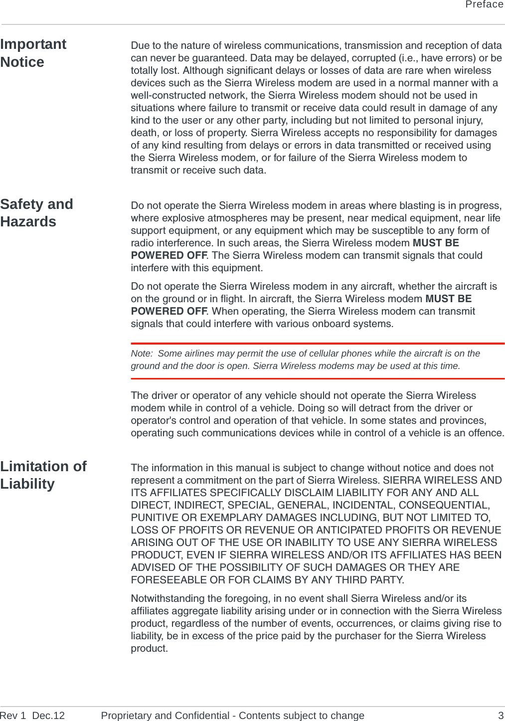
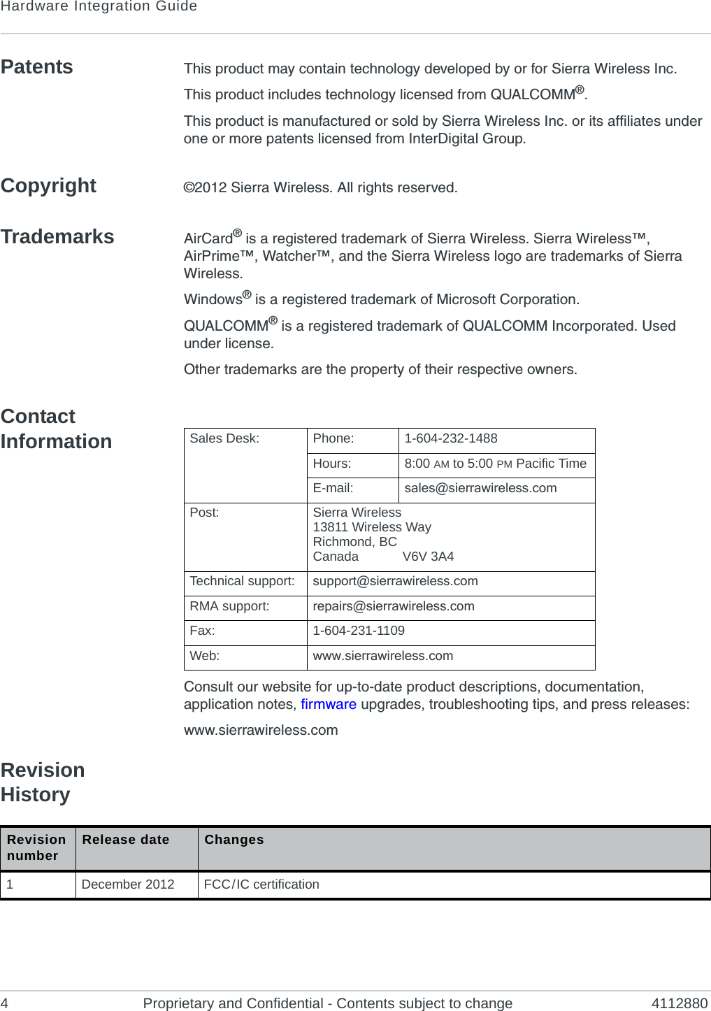
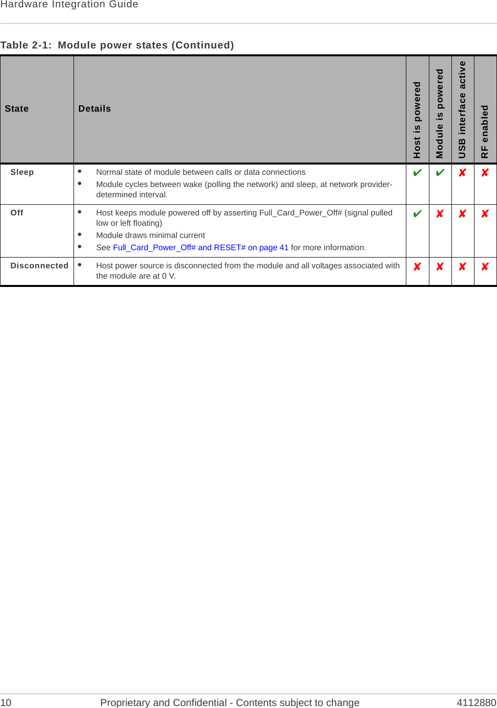
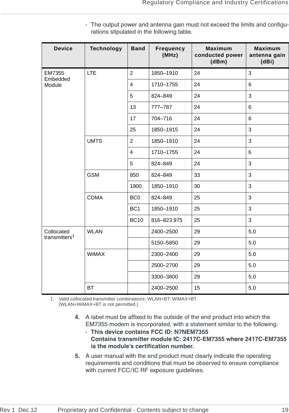
AirPrime EM7355Hardware Integration Guide4112880Rev 1Distribution under NDA only Contents subject to change
PrefaceRev 1  Dec.12 Proprietary and Confidential - Contents subject to change 3Important NoticeDue to the nature of wireless communications, transmission and reception of data can never be guaranteed. Data may be delayed, corrupted (i.e., have errors) or be totally lost. Although significant delays or losses of data are rare when wireless devices such as the Sierra Wireless modem are used in a normal manner with a well-constructed network, the Sierra Wireless modem should not be used in situations where failure to transmit or receive data could result in damage of any kind to the user or any other party, including but not limited to personal injury, death, or loss of property. Sierra Wireless accepts no responsibility for damages of any kind resulting from delays or errors in data transmitted or received using the Sierra Wireless modem, or for failure of the Sierra Wireless modem to transmit or receive such data.Safety and HazardsDo not operate the Sierra Wireless modem in areas where blasting is in progress, where explosive atmospheres may be present, near medical equipment, near life support equipment, or any equipment which may be susceptible to any form of radio interference. In such areas, the Sierra Wireless modem MUST BE POWERED OFF. The Sierra Wireless modem can transmit signals that could interfere with this equipment.Do not operate the Sierra Wireless modem in any aircraft, whether the aircraft is on the ground or in flight. In aircraft, the Sierra Wireless modem MUST BE POWERED OFF. When operating, the Sierra Wireless modem can transmit signals that could interfere with various onboard systems.Note: Some airlines may permit the use of cellular phones while the aircraft is on the ground and the door is open. Sierra Wireless modems may be used at this time.The driver or operator of any vehicle should not operate the Sierra Wireless modem while in control of a vehicle. Doing so will detract from the driver or operator's control and operation of that vehicle. In some states and provinces, operating such communications devices while in control of a vehicle is an offence.Limitation of LiabilityThe information in this manual is subject to change without notice and does not represent a commitment on the part of Sierra Wireless. SIERRA WIRELESS AND ITS AFFILIATES SPECIFICALLY DISCLAIM LIABILITY FOR ANY AND ALL DIRECT, INDIRECT, SPECIAL, GENERAL, INCIDENTAL, CONSEQUENTIAL, PUNITIVE OR EXEMPLARY DAMAGES INCLUDING, BUT NOT LIMITED TO, LOSS OF PROFITS OR REVENUE OR ANTICIPATED PROFITS OR REVENUE ARISING OUT OF THE USE OR INABILITY TO USE ANY SIERRA WIRELESS PRODUCT, EVEN IF SIERRA WIRELESS AND/OR ITS AFFILIATES HAS BEEN ADVISED OF THE POSSIBILITY OF SUCH DAMAGES OR THEY ARE FORESEEABLE OR FOR CLAIMS BY ANY THIRD PARTY.Notwithstanding the foregoing, in no event shall Sierra Wireless and/or its affiliates aggregate liability arising under or in connection with the Sierra Wireless product, regardless of the number of events, occurrences, or claims giving rise to liability, be in excess of the price paid by the purchaser for the Sierra Wireless product.
Hardware Integration Guide4 Proprietary and Confidential - Contents subject to change 4112880Patents This product may contain technology developed by or for Sierra Wireless Inc.This product includes technology licensed from QUALCOMM®.This product is manufactured or sold by Sierra Wireless Inc. or its affiliates under one or more patents licensed from InterDigital Group.Copyright ©2012 Sierra Wireless. All rights reserved.Trademarks AirCard® is a registered trademark of Sierra Wireless. Sierra Wireless™, AirPrime™, Watcher™, and the Sierra Wireless logo are trademarks of Sierra Wireless.Windows® is a registered trademark of Microsoft Corporation.QUALCOMM® is a registered trademark of QUALCOMM Incorporated. Used under license.Other trademarks are the property of their respective owners.Contact InformationConsult our website for up-to-date product descriptions, documentation, application notes, firmware upgrades, troubleshooting tips, and press releases:www.sierrawireless.comRevision History          Sales Desk: Phone: 1-604-232-1488Hours: 8:00 AM to 5:00 PM Pacific TimeE-mail: sales@sierrawireless.comPost: Sierra Wireless13811 Wireless WayRichmond, BCCanada            V6V 3A4Technical support: support@sierrawireless.comRMA support: repairs@sierrawireless.comFax: 1-604-231-1109Web: www.sierrawireless.comRevision number Release date Changes1December 2012 FCC / IC certification
Rev 1  Dec.12 Proprietary and Confidential - Contents subject to change 5ContentsIntroduction . . . . . . . . . . . . . . . . . . . . . . . . . . . . . . . . . . . . . . . . . . . . . . . . . . . . .7Accessories . . . . . . . . . . . . . . . . . . . . . . . . . . . . . . . . . . . . . . . . . . . . . . . . . .  7Required connectors  . . . . . . . . . . . . . . . . . . . . . . . . . . . . . . . . . . . . . . . . . . .  7Power . . . . . . . . . . . . . . . . . . . . . . . . . . . . . . . . . . . . . . . . . . . . . . . . . . . . . . . . . .9Power supply . . . . . . . . . . . . . . . . . . . . . . . . . . . . . . . . . . . . . . . . . . . . . . . . .  9Module power states  . . . . . . . . . . . . . . . . . . . . . . . . . . . . . . . . . . . . . . . . . . .  9RF Specifications  . . . . . . . . . . . . . . . . . . . . . . . . . . . . . . . . . . . . . . . . . . . . . . .11RF connections  . . . . . . . . . . . . . . . . . . . . . . . . . . . . . . . . . . . . . . . . . . . . . .  12Shielding   . . . . . . . . . . . . . . . . . . . . . . . . . . . . . . . . . . . . . . . . . . . . . . . . .12Antenna and cabling   . . . . . . . . . . . . . . . . . . . . . . . . . . . . . . . . . . . . . . . .13Ground connection. . . . . . . . . . . . . . . . . . . . . . . . . . . . . . . . . . . . . . . . . . . .  14Interference and sensitivity. . . . . . . . . . . . . . . . . . . . . . . . . . . . . . . . . . . . . .  14Interference from other wireless devices  . . . . . . . . . . . . . . . . . . . . . . . . .14Host-generated RF interference   . . . . . . . . . . . . . . . . . . . . . . . . . . . . . . .14Device-generated RF interference . . . . . . . . . . . . . . . . . . . . . . . . . . . . . .15Methods to mitigate decreased Rx performance  . . . . . . . . . . . . . . . . . . .15Radiated Spurious Emissions (RSE)  . . . . . . . . . . . . . . . . . . . . . . . . . . . .15Radiated sensitivity measurement . . . . . . . . . . . . . . . . . . . . . . . . . . . . . . . .  16Regulatory Compliance and Industry Certifications . . . . . . . . . . . . . . . . . . .17Important notice . . . . . . . . . . . . . . . . . . . . . . . . . . . . . . . . . . . . . . . . . . . . . .  17Safety and hazards  . . . . . . . . . . . . . . . . . . . . . . . . . . . . . . . . . . . . . . . . . . .  17Important compliance information for North American users . . . . . . . . . . . .  18Acronyms   . . . . . . . . . . . . . . . . . . . . . . . . . . . . . . . . . . . . . . . . . . . . . . . . . . . . .21Index . . . . . . . . . . . . . . . . . . . . . . . . . . . . . . . . . . . . . . . . . . . . . . . . . . . . . . . . .  27
Hardware Integration Guide6 Proprietary and Confidential - Contents subject to change 4112880
Rev 1  Dec.12 Proprietary and Confidential - Contents subject to change 711: IntroductionThe Sierra Wireless EM7355 Embedded Module is an M.2 modem that provides LTE, DC-HSPA+, HSPA+, HSDPA, HSUPA, WCDMA, GSM, GPRS, EDGE, CDMA, and GNSS connectivity for notebook, ultrabook, and tablet computers over several radio frequency bands. The device also supports 2G / 3G roaming.AccessoriesA hardware development kit is available for AirPrime M.2 modules. The kit contains hardware components for evaluating and developing with the module, including:•Development board•Cables•Antennas•Other accessoriesFor over-the-air LTE testing, ensure that suitable antennas are used.Required connectorsTabl e  1-1 describes the connectors used to integrate the EM7355 Embedded Module into your host device.Table 1-1: Required host-module connectors Connector type DescriptionRF cables •Mate with M.2-spec connectors•Three connector jacksEDGE (67 pin) •Slot B compatible — Per the M.2 standard (PCI Express NGFF (M.2) Electromechanical Specification Revision 0.7), a generic 75 pin position EDGE connector on the motherboard uses a mechanical key to mate with the 67 pin notched module connector.•Manufacturers include LOTES (part #APCI0018-P001A01), Kyocera, JAE, Tyco, and Longwell.SIM •Industry-standard connector.
Hardware Integration Guide8 Proprietary and Confidential - Contents subject to change 4112880
Rev 1  Dec.12 Proprietary and Confidential - Contents subject to change 922: PowerPower supplyThe host provides power to the EM7355 through multiple power and ground pins. The host must provide safe and continuous power (via battery or a regulated power supply) at all times; the module does not have an independent power supply, or protection circuits to guard against electrical issues.For detailed pinout and voltage / current requirements of this module, see the AirPrime EM7355 Product Technical Specification & Customer Design Guidelines.Module power statesThe module has five power states, as described in Ta b l e  2-1. Table 2-1: Module power states State DetailsHost is poweredModule is poweredUSB interface activeRF enabledNormal(Default state)•Module is active•Default state. Occurs when VCC is first applied, Full_Card_Power_Off# is deasserted (pulled high), and W_DISABLE#1 is deasserted•Module is capable of placing / receiving calls, or establishing data connections on the wireless network•Current consumption is affected by several factors, including:•Radio band being used•Transmit power•Receive gain settings•Data rate   Low power(‘Airplane mode’)•Module is active•Module enters this state:•Under host interface control:·Host issues AT+CFUN=0 ([1] AT Command Set for User Equipment (UE) (Release 6) (Doc# 3GPP TS 27.007))), or·Host asserts W_DISABLE#1, after AT!PCOFFEN=0 has been issued.•Automatically, when critical temperature or voltage trigger limits have been reached))   
Hardware Integration Guide10 Proprietary and Confidential - Contents subject to change 4112880Sleep •Normal state of module between calls or data connections•Module cycles between wake (polling the network) and sleep, at network provider-determined interval.   Off •Host keeps module powered off by asserting Full_Card_Power_Off# (signal pulled low or left floating)•Module draws minimal current•See Full_Card_Power_Off# and RESET# on page 41 for more information.  Disconnected •Host power source is disconnected from the module and all voltages associated with the module are at 0 V.   Table 2-1:  Module power states (Continued)State DetailsHost is poweredModule is poweredUSB interface activeRF enabled
Rev 1  Dec.12 Proprietary and Confidential - Contents subject to change 1133: RF SpecificationsThe EM7355 operates on the frequency bands listed below.    Table 3-1: LTE frequency band support Band FrequenciesBand 2 Tx: 1850–1910 MHzRx: 1930–1990 MHzBand 4 (AWS) Tx: 1710–1755 MHzRx: 2110–2155 MHzBand 5 Tx: 824–849 MHzRx: 869–894 MHzBand 13 Tx: 777–787 MHzRx: 746–756 MHzBand 17 Tx: 704–716 MHzRx: 734–746 MHzBand 25 Tx: 1850–1915 MHzRx: 1930–1995 MHzTable 3-2: WCDMA frequency band support11. WCDMA channel spacing is 5 MHz, but this can be adjusted to optimize performance in a particular deployment scenario.Band FrequenciesBand 1WCDMA 2100 Tx: 1920–1980 MHzRx: 2110–2170 MHzBand 2WCDMA 1900 Tx: 1850–1910 MHzRx: 1930–1990 MHzBand 4AWS 1700/2100 Tx: 1710–1755 MHzRx: 2110–2155 MHzBand 5WCDMA 850 Tx: 824–849 MHzRx: 869–894 MHzBand 8WCDMA 900 Tx: 880–915 MHzRx: 925–960 MHzTable 3-3: GSM frequency band support Band FrequenciesGSM 850 Tx: 824–849 MHzRx: 869–894 MHzEGSM 900 Tx: 880–915 MHzRx: 925–960 MHz
Hardware Integration Guide12 Proprietary and Confidential - Contents subject to change 4112880RF connectionsWhen attaching antennas to the module:•Use any of the following (or compatible) 2x2 mm RF receptacle connectors to attach antennas to the module’s connection points•Match coaxial connections between the module and the antenna to 50 .•Minimize RF cable losses to the antenna; the recommended maximum cable loss for antenna cabling is 0.5 dB.•To ensure best thermal performance, if possible use the mounting hole to attach (ground) the device to a metal chassis.Note: If the antenna connection is shorted or open, the modem will not sustain permanent damage.ShieldingThe module is fully shielded to protect against EMI and must not be removed.GSM 1800 Tx: 1710–1785 MHzRx: 1805–1880 MHzGSM 1900 Tx: 1850–1910 MHzRx: 1930–1990 MHzTable 3-4: CDMA frequency band support Band FrequenciesBand Class 0(Cellular 800 MHz) Tx: 824–849 MHzRx: 869–894 MHzBand Class 1(PCS) Tx: 1850–1910 MHzRx: 1930–1990 MHzBand Class 10(Secondary 800 MHz)1Tx: 816–824 MHzRx: 861–869 MHz1. BC10 subclasses 2 and 3 (system designator C and D) are sup-portedTable 3-5: GNSS frequency band support Band FrequenciesNarrow-band GPS Rx: 1575.42 MHzWide-band GPS + GLONASS Rx: 1565–1606 MHzTable 3-3:  GSM frequency band support (Continued)Band Frequencies
RF SpecificationsRev 1  Dec.12 Proprietary and Confidential - Contents subject to change 13Antenna and cablingWhen selecting the antenna and cable, it is critical to RF performance to match antenna gain and cable loss.Choosing the correct antenna and cablingWhen matching antennas and cabling:•The antenna (and associated circuitry) should have a nominal impedance of 50  with a return loss of better than 10 dB across each frequency band of operation.•The system gain value affects both radiated power and regulatory (FCC, IC, CE, etc.) test results.Designing custom antennasConsider the following points when designing custom antennas:•A skilled RF engineer should do the development to ensure that the RF performance is maintained.•If both UMTS and CDMA modules will be installed in the same platform, you may want to develop separate antennas for maximum performance.Determining the antenna’s locationWhen deciding where to put the antennas:•Antenna location may affect RF performance. Although the module is shielded to prevent interference in most applications, the placement of the antenna is still very important — if the host device is insufficiently shielded, high levels of broadband or spurious noise can degrade the module’s perfor-mance.•Connecting cables between the module and the antenna must have 50  impedance. If the impedance of the module is mismatched, RF performance is reduced significantly.•Antenna cables should be routed, if possible, away from noise sources (switching power supplies, LCD assemblies, etc.). If the cables are near the noise sources, the noise may be coupled into the RF cable and into the antenna.Disabling the diversity antenna•For LTE / UMTS bands, use the AT command !RXDEN=0 to disable receive diversity or  !RXDEN=1 to enable receive diversity.•For CDMA bands, use the AT command !DIVERSITY to enable or disable receive diversity.Note: A diversity antenna is used to improve connection quality and reliability through redundancy. Because two antennas may experience difference interference effects (signal distortion, delay, etc.), when one antenna receives a degraded signal, the other may not be similarly affected.
Hardware Integration Guide14 Proprietary and Confidential - Contents subject to change 4112880Ground connectionWhen connecting the module to system ground:•Prevent noise leakage by establishing a very good ground connection to the module through the host connector.•Connect to system ground using the module’s mounting hole.•Minimize ground noise leakage into the RF.Depending on the host board design, noise could potentially be coupled to the module from the host board. This is mainly an issue for host designs that have signals traveling along the length of the module, or circuitry operating at both ends of the module interconnects.Interference and sensitivitySeveral interference sources can affect the module’s RF performance (RF desense). Common sources include power supply noise and device-generated RF.RF desense can be addressed through a combination of mitigation techniques (Methods to mitigate decreased Rx performance on page 15) and radiated sensitivity measurement (Radiated sensitivity measurement on page 16).Note: The EM7355 is based on ZIF (Zero Intermediate Frequency) technologies. When performing EMC (Electromagnetic Compatibility) tests, there are no IF (Intermediate Frequency) components from the module to consider.Interference from other wireless devicesWireless devices operating inside the host device can cause interference that affects the module.To determine the most suitable locations for antennas on your host device, evaluate each wireless device’s radio system, considering the following:•Any harmonics, sub-harmonics, or cross-products of signals generated by wireless devices that fall in the module’s Rx range may cause spurious response, resulting in decreased Rx performance.•The Tx power and corresponding broadband noise of other wireless devices may overload or increase the noise floor of the module’s receiver, resulting in Rx desense.The severity of this interference depends on the closeness of the other antennas to the module’s antenna. To determine suitable locations for each wireless device’s antenna, thoroughly evaluate your host device’s design.Host-generated RF interferenceAll electronic computing devices generate RF interference that can negatively affect the receive sensitivity of the module.
RF SpecificationsRev 1  Dec.12 Proprietary and Confidential - Contents subject to change 15Proximity of host electronics to the antenna in wireless devices can contribute to decreased Rx performance. Components that are most likely to cause this include:•Microprocessor and memory•Display panel and display drivers•Switching-mode power suppliesDevice-generated RF interferenceThe module can cause interference with other devices. Wireless devices such as AirPrime embedded modules transmit in bursts (pulse transients) for set durations (RF burst frequencies). Hearing aids and speakers convert these burst frequencies into audible frequencies, resulting in audible noise. Methods to mitigate decreased Rx performanceIt is important to investigate sources of localized interference early in the design cycle. To reduce the effect of device-generated RF on Rx performance:•Put the antenna as far as possible from sources of interference. The drawback is that the module may be less convenient to use.•Shield the host device. The module itself is well shielded to avoid external interference. However, the antenna cannot be shielded for obvious reasons. In most instances, it is necessary to employ shielding on the components of the host device (such as the main processor and parallel bus) that have the highest RF emissions. •Filter out unwanted high-order harmonic energy by using discrete filtering on low frequency lines.•Form shielding layers around high-speed clock traces by using multi-layer PCBs.•Route antenna cables away from noise sources.Radiated Spurious Emissions (RSE)When designing an antenna for use with AirPrime embedded modules, the host device with an AirPrime embedded module must satisfy the radiated spurious emission (RSE) test cases described in:•(CDMA) Refer to CDMA standards for receive-only mode, and local regulatory bodies for transmit mode (transmitter is operating).•CE/ETSI EN 301 908 (WCDMA), test numbers 5.3.1 (‘Radiated Emissions (UE)’)•CE/ETSI EN 301 511 (GSM), test 5.2.16 (‘Radiated Spurious Emissions - MS allocated a channel’). This test uses the procedure and requirement outlined in 3GPP 51.010 (GSM) section 12.2.1 of the same test name.Note that antenna impedance affects radiated emissions, which must be compared against the conducted 50-ohm emissions baseline. (AirPrime embedded modules meet the 50-ohm conducted emissions requirement.)
Hardware Integration Guide16 Proprietary and Confidential - Contents subject to change 4112880Note: GSM spurious emissions are most likely to have RSE issues, but in general, RSE requirements must be met on all models with user-designed antennas.Radiated sensitivity measurementA wireless host device contains many noise sources that contribute to a reduction in Rx performance.To determine the extent of any receiver performance desensitization due to self-generated noise in the host device, over-the-air (OTA) or radiated testing is required. This testing can be performed by Sierra Wireless or you can use your own OTA test chamber for in-house testing.
Rev 1  Dec.12 Proprietary and Confidential - Contents subject to change 1744: Regulatory Compliance and Industry CertificationsThis module is designed to meet, and upon commercial release, will meet the requirements of the following regulatory bodies and regulations, where applicable:•Federal Communications Commission (FCC) of the United States•The Certification and Engineering Bureau of Industry Canada (IC)•The National Communications Commission (NCC) of Taiwan, Republic of ChinaUpon commercial release, the following industry certifications will have been obtained, where applicable:•GCF-CC (For Verizon 2G / 3G approval)•PTCRB•CDG2Additional certifications may be obtained upon customer request — contact your Sierra Wireless account representative for details.Additional testing and certification may be required for the end product with an embedded EM7355 modem and are the responsibility of the OEM. Sierra Wireless offers professional services-based assistance to OEMs with the testing and certification process, if required.Important noticeBecause of the nature of wireless communications, transmission and reception of data can never be guaranteed. Data may be delayed, corrupted (i.e., have errors) or be totally lost. Although significant delays or losses of data are rare when wireless devices such as the Sierra Wireless modem are used in a normal manner with a well-constructed network, the Sierra Wireless modem should not be used in situations where failure to transmit or receive data could result in damage of any kind to the user or any other party, including but not limited to personal injury, death, or loss of property. Sierra Wireless and its affiliates accept no responsibility for damages of any kind resulting from delays or errors in data transmitted or received using the Sierra Wireless modem, or for failure of the Sierra Wireless modem to transmit or receive such data.Safety and hazardsDo not operate your EM7355 modem:•In areas where blasting is in progress
Hardware Integration Guide18 Proprietary and Confidential - Contents subject to change 4112880•Where explosive atmospheres may be present including refuelling points, fuel depots, and chemical plants•Near medical equipment, life support equipment, or any equipment which may be susceptible to any form of radio interference. In such areas, the EM7355 modem MUST BE POWERED OFF. Otherwise, the EM7355 modem can transmit signals that could interfere with this equipment.In an aircraft, the EM7355 modem MUST BE POWERED OFF. Otherwise, the EM7355 modem can transmit signals that could interfere with various onboard systems and may be dangerous to the operation of the aircraft or disrupt the cellular network. Use of a cellular phone in an aircraft is illegal in some jurisdictions. Failure to observe this instruction may lead to suspension or denial of cellular telephone services to the offender, or legal action or both.Some airlines may permit the use of cellular phones while the aircraft is on the ground and the door is open. The EM7355 modem may be used normally at this time.Important compliance information for North American usersNote: Details are preliminary and subject to change.The EM7355 modem has been granted modular approval for mobile applications. Integrators may use the EM7355 modem in their final products without additional FCC / IC (Industry Canada) certification if they meet the following conditions. Otherwise, additional FCC / IC approvals must be obtained.1. At least 20 cm separation distance between the antenna and the user’s body must be maintained at all times.2. To comply with FCC / IC regulations limiting both maximum RF output power and human exposure to RF radiation, the maximum antenna gain including cable loss in a mobile-only exposure condition must not exceed:·6.5 dBi in Cellular band·3.0 dBi in PCS band·3.0 dBi in LTE Band 2·6.0 dBi in LTE Band 4·6.5 dBi in LTE Band 5·9.0 dBi in LTE Band 13 (Note: LTE Band 13 is not permitted in Canada.)·9.0 dBi in LTE Band 17 (Note: LTE Band 17 is not permitted in Canada.)·3.0 dBi in LTE Band 253. The EM7355 modem may transmit simultaneously with other collocated radio transmitters within a host device, provided the following conditions are met:·Each collocated radio transmitter has been certfied by FCC / IC for mobile application.·At least 20 cm separation distance between the antennas of the collocated transmitters and the user’s body must be maintained at all times.
Regulatory Compliance and Industry CertificationsRev 1  Dec.12 Proprietary and Confidential - Contents subject to change 19·The output power and antenna gain must not exceed the limits and configu-rations stipulated in the following table.4. A label must be affixed to the outside of the end product into which the EM7355 modem is incorporated, with a statement similar to the following:· This device contains FCC ID: N7NEM7355Contains transmitter module IC: 2417C-EM7355 where 2417C-EM7355 is the module’s certification number.5. A user manual with the end product must clearly indicate the operating requirements and conditions that must be observed to ensure compliance with current FCC / IC RF exposure guidelines.Device Technology Band Frequency(MHz) Maximum conducted power(dBm)Maximum antenna gain(dBi)EM7355 Embedded ModuleLTE 21850–1910 24 341710–1755 24 65824–849 24 313 777–787 24 617 704–716 24 625 1850–1915 24 3UMTS 21850–1910 24 341710–1755 24 65824–849 24 3GSM 850 824–849 33 31900 1850–1910 30 3CDMA BC0 824–849 25 3BC1 1850–1910 25 3BC10 816–823.975 25 3Collocated transmitters1WLAN 2400–2500 29 5.05150–5850 29 5.0WiMAX 2300–2400 29 5.02500–2700 29 5.03300–3800 29 5.0BT 2400–2500 15 5.01. Valid collocated transmitter combinations: WLAN+BT; WiMAX+BT.(WLAN+WiMAX+BT is not permitted.)
Hardware Integration Guide20 Proprietary and Confidential - Contents subject to change 4112880The end product with an embedded EM7355 modem may also need to pass the FCC Part 15 unintentional emission testing requirements and be properly authorized per FCC Part 15.Note: If this module is intended for use in a portable device, you are responsible for separate approval to satisfy the SAR requirements of FCC Part 2.1093 and IC RSS-102.
Rev 1  Dec.12 Proprietary and Confidential - Contents subject to change2155: AcronymsTable 5-1: Acronyms and definitions Acronym or term Definition1xEV-DO Single Carrier (1X) EVolution – Data Only. A high-speed standard for cellular packet data communications.Supports Internet connections with data rates up to 3.1 Mbps (downlink from the network) and 1.8 Mbps (uplink to the network). Average data rates are roughly: for Rev. A: 600 1300 kbps (downlink from the network) and 300 400 kbps (uplink to the network); for Rev. 0: 400 700 kbps (downlink from the network) and 40 80 kbps (uplink to the network). Actual speed depends on the network conditions. Compare to 1X.1X Single Carrier (1X) Radio Transmission Technology. A high-speed standard for cellular packet data communications. Supports Internet connections with data rates up to 153 kbps (simultaneously in each direction—downlink and uplink). Actual speed depends on the network conditions. Compare to 1xEV-DO.3GPP 3rd Generation Partnership Project8PSK Octagonal Phase Shift KeyingAGC Automatic Gain ControlA-GPS Assisted GPSA-GNSS Assisted GNSSAPI Application Programming InterfaceBER Bit Error Rate — A measure of receive sensitivityBLER Block Error Ratebluetooth Wireless protocol for data exchange over short distancesCAIT CDMA Air Interface ToolCDG CDMA Development Group—a consortium of companies that develop and promote the products and services for CDMA wireless systems.CDMA Code Division Multiple Access.A wideband spread spectrum technique used in digital cellular, personal communications services, and other wireless networks. Wide channels (1.25 MHz) are obtained through spread spectrum transmissions, thus allowing many active users to share the same channel. Each user is assigned a unique digital code, which differentiates the individual conversations on the same channel.CQI Channel Quality IndicationCOM Communication portCS Circuit-switchedCW Continuous waveform
Hardware Integration Guide22 Proprietary and Confidential - Contents subject to change 4112880dB Decibel = 10 x log10 (P1 / P2)P1 is calculated power; P2 is reference powerDecibel = 20 x log10 (V1 / V2)V1 is calculated voltage, V2 is reference voltagedBm A logarithmic (base 10) measure of relative power (dB for decibels); relative to milliwatts (m). A dBm value will be 30 units (1000 times) larger (less negative) than a dBW value, because of the difference in scale (milliwatts vs. watts).DC-HSPA+ Dual Carrier HSPA+DCS Digital Cellular SystemA cellular communication infrastructure that uses the 1.8 GHz radio spectrum.DL Downlink (network to mobile)DUN Dial-Up NetworkingDRX Discontinuous ReceptionDSM Distributed Shared MemoryDUT Device Under TestEDGE Enhanced Data rates for GSM EvolutioneHRPD Evolved High Rate Packet Data — Enhances traditional 1xEV-DO to enable LTE to CDMA handover.EIRP Effective (or Equivalent) Isotropic Radiated PowerEMC Electromagnetic CompatibilityEMI Electromagnetic InterferenceERP Effective Radiated PowerESD Electrostatic DischargeFCC Federal Communications CommissionThe U.S. federal agency that is responsible for interstate and foreign communications. The FCC regulates commercial and private radio spectrum management, sets rates for communications services, determines standards for equipment, and controls broadcast licensing. Consult www.fcc.gov.FDMA Frequency Division Multiple AccessFER Frame Error Rate — A measure of receive sensitivity.firmware Software stored in ROM or EEPROM; essential programs that remain even when the system is turned off. Firmware is easier to change than hardware but more permanent than software stored on disk.FOTA Firmware Over The Air — Technology used to download firmware upgrades directly from the service provider, over the air.FOV Field Of ViewTable 5-1:  Acronyms and definitions (Continued)Acronym or term Definition
AcronymsRev 1  Dec.12 Proprietary and Confidential - Contents subject to change23FSN Factory Serial Number—A unique serial number assigned to the mini card during manufacturing.GCF Global Certification ForumGLONASS Global Navigation Satellite System — A Russian system that uses a series of 24 satellites in middle circular orbit to provide navigational data.GMSK Gaussian Minimum Shift Keying modulationGNSS Global Navigation Satellite Systems (GPS plus GLONASS)GPRS General Packet Radio ServiceGPS Global Positioning SystemAn American system that uses a series of 24 satellites in middle circular orbit to provide navigational data.GSM Global System for Mobile CommunicationsHost The device into which an embedded module is integratedHSDPA High Speed Downlink Packet AccessHSPA+ Enhanced HSPA, as defined in 3GPP Release 7 and beyondHSUPA High Speed Uplink Packet AccessHz Hertz = 1 cycle / secondIC Industry CanadaIF Intermediate FrequencyIMEI International Mobile Equipment IdentityIMS IP Multimedia Subsystem — Architectural framework for delivering IP multimedia services.inrush current Peak current drawn when a device is connected or powered oninter-RAT Radio Access TechnologyIOT Interoperability TestingIS Interim Standard.After receiving industry consensus, the TIA forwards the standard to ANSI for approval.IS-2000 3G radio standards for voice and data (CDMA only)IS-95 2G radio standards targeted for voice (cdmaONE)LED Light Emitting Diode.A semiconductor diode that emits visible or infrared light.LHCP Left-Hand Circular PolarizedLNA Low Noise AmplifierTable 5-1:  Acronyms and definitions (Continued)Acronym or term Definition
Hardware Integration Guide24 Proprietary and Confidential - Contents subject to change 4112880LPM Low Power ModeLPT Line Print TerminalLTE Long Term Evolution—a high-performance air interface for cellular mobile communication systems.MCS Modulation and Coding SchemeMHz Megahertz = 10e6 HzMEID Mobile Equipment Identifier — The unique second-generation serial number assigned to the minicard for use on the wireless network.MIMO Multiple Input Multiple Output—wireless antenna technology that uses multiple antennas at both transmitter and receiver side. This improves performance.NAS / AS Network Access ServerNC No ConnectNIC Network Interface CardNMEA National Marine Electronics AssociationOEM Original Equipment Manufacturer—a company that manufactures a product and sells it to a reseller.OFDMA Orthogonal Frequency Division Multiple AccessOMA DM Open Mobile Alliance Device Management — A device management protocol.OTA ‘Over the air’ (or radiated through the antenna)PA Power Amplifierpacket A short, fixed-length block of data, including a header, that is transmitted as a unit in a communications network.PCB Printed Circuit BoardPCS Personal Communication SystemA cellular communication infrastructure that uses the 1.9 GHz radio spectrum.PDN Packet Data NetworkPMI Pre-coding Matrix IndexPSS Primary synchronisation signalPST Product Support ToolsPTCRB PCS Type Certification Review BoardQAM Quadrature Amplitude Modulation.This form of modulation uses amplitude, frequency, and phase to transfer data on the carrier wave.QMI Qualcomm MSM/Modem InterfaceTable 5-1:  Acronyms and definitions (Continued)Acronym or term Definition
AcronymsRev 1  Dec.12 Proprietary and Confidential - Contents subject to change25QOS Quality of ServiceQPSK Quadrature Phase-Shift KeyingQPST Qualcomm Product Support ToolsRAT Radio Access TechnologyRF Radio FrequencyRI Ring Indicatorroaming A cellular subscriber is in an area where service is obtained from a cellular service provider that is not the subscriber’s provider.RSE Radiated Spurious EmissionsRSSI Received Signal Strength IndicationSDK Software Development KitSED Smart Error DetectionSensitivity (Audio) Measure of lowest power signal that the receiver can measure.Sensitivity (RF) Measure of lowest power signal at the receiver input that can provide a prescribed BER / BLER / SNR value at the receiver output.SG An LTE signaling interface for SMS (“SMS over SGs”)SIB System Information BlockSIM Subscriber Identity Module. Also referred to as USIM or UICC.SIMO Single Input Multiple Output—smart antenna technology that uses a single antenna at the transmitter side and multiple antennas at the receiver side. This improves performance and security.SISO Single Input Single Output—antenna technology that uses a single antenna at both the transmitter side and the receiver side.SKU Stock Keeping Unit—identifies an inventory item: a unique code, consisting of numbers or letters and numbers, assigned to a product by a retailer for purposes of identification and inventory control.SMS Short Message Service.A feature that allows users of a wireless device on a wireless network to receive or transmit short electronic alphanumeric messages (up to 160 characters, depending on the service provider).S/N Signal-to-noise (ratio)SNR Signal-to-Noise RatioSOF Start of Frame — A USB function.SSS Secondary synchronisation signal.Table 5-1:  Acronyms and definitions (Continued)Acronym or term Definition
Hardware Integration Guide26 Proprietary and Confidential - Contents subject to change 4112880SUPL Secure User Plane LocationTIA/EIA Telecommunications Industry Association / Electronics Industry Association.A standards setting trade organization, whose members provide communications and information technology products, systems, distribution services and professional services in the United States and around the world. Consult www.tiaonline.org.TIS Total Isotropic SensitivityTRP Total Radiated PowerUDK Universal Development Kit (for PCI Express Mini Cards)UE User EquipmentUICC Universal Integrated Circuit Card (Also referred to as a SIM card.)UL Uplink (mobile to network)UMTS Universal Mobile Telecommunications SystemUSB Universal Serial BusUSIM Universal Subscriber Identity Module (UMTS)VCC Supply voltageVSWR Voltage Standing Wave RatioWAN Wide Area NetworkWCDMA Wideband Code Division Multiple Access (also referred to as UMTS)WLAN Wireless Local Area NetworkZIF Zero Intermediate FrequencyTable 5-1:  Acronyms and definitions (Continued)Acronym or term Definition
Rev 1  Dec.12 Proprietary and Confidential - Contents subject to change 27IndexAaccessories,  7acronyms and definitions,  21– 26antennaconnection considerations,  12custom, design,  13diversity antenna, disabling,  13limit, matching coaxial connections,  12location, considerations,  13matching, considerations,  13maximum cable loss,  12routing,  13approvals, regulatory and industry,  17Bbands supported, RFCDMA,  12GSM,  11,  12LTE,  11WCDMA,  11Ccable lossantenna, maximum,  12CDMAfrequency band support,  12connectiongrounding,  14connectors, requiredhost-module,  7Ddesense. See RFdiversity antennadisabling,  13EEDGEconnector, required,  7Ffiltering, RF desense,  15frequency band supportCDMA,  12GSM,  11,  12LTE,  11WCDMA,  11Ggainmaximum,  18groundingconnection considerations,  14GSMfrequency band support,  11,  12Iimpedancemodule–antenna,  13industry approvals,  17interferencedevice generated,  15host-generated,  14wireless devices,  14LLTEfrequency band support,  11Nnoiseleakage, minimizing,  14PPCBmulti-layer, shielding for RF desense,  15Rradiated sensitivity measurement,  16radiated spurious emissions,  15regulatory approvals,  17regulatory information,  17– 20FCC,  18limitation of liability,  17safety and hazards,  17
Hardware Integration Guide28 Proprietary and Confidential - Contents subject to change 4112880RFantenna cable loss, maximum,  12antenna connection, considerations,  12connectors, required,  7desensedevice-generated,  14harmonic energy, filtering,  15mitigation suggestions,  15shielding suggestions,  15interferenceother devices,  15wireless devices,  14RF bands supportedCDMA,  12GSM,  11,  12LTE,  11WCDMA,  11RF specifications,  11– 16RSE,  15Ssensitivityradiated measurement, overview,  16shieldingmodule, compliance,  12reducing RF desense,  15SIMconnector, required,  7specificationsRF,  11– 16WWCDMAfrequency band support,  11ZZIF (Zero Intermediate Frequency),  14

Navigation menu