Sierra Wireless EM7700 Cellular/PCS WCDMA and LTE Band 4/17 Modem User Manual AirPrime EM7700 Hardware Integration Guide

Sierra Wireless Inc. Cellular/PCS WCDMA and LTE Band 4/17 Modem AirPrime EM7700 Hardware Integration Guide

TempConfidential_EM7700 HW Integration Guide (FCC) v2
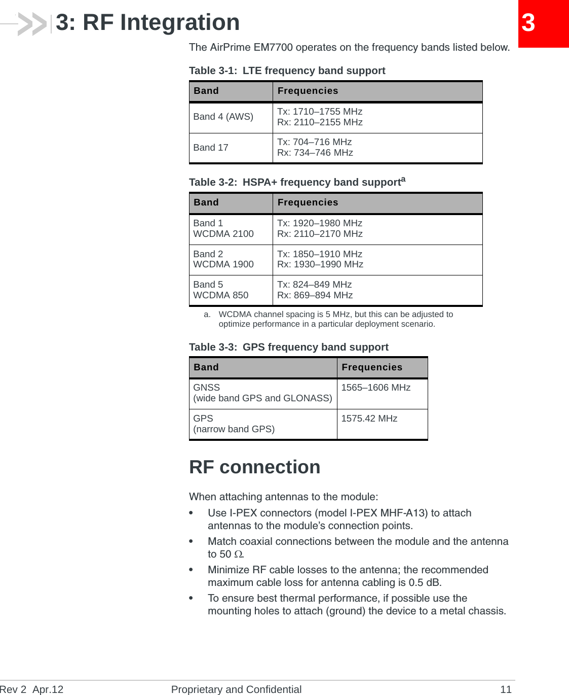
AirPrime EM7700Hardware Integration Guide4112206Rev 2
PrefaceRev 2  Apr.12 Proprietary and Confidential 3Important NoticeDue to the nature of wireless communications, transmission and reception of data can never be guaranteed. Data may be delayed, corrupted (i.e., have errors) or be totally lost. Although significant delays or losses of data are rare when wireless devices such as the Sierra Wireless modem are used in a normal manner with a well-constructed network, the Sierra Wireless modem should not be used in situations where failure to transmit or receive data could result in damage of any kind to the user or any other party, including but not limited to personal injury, death, or loss of property. Sierra Wireless accepts no responsibility for damages of any kind resulting from delays or errors in data transmitted or received using the Sierra Wireless modem, or for failure of the Sierra Wireless modem to transmit or receive such data.Safety and HazardsDo not operate the Sierra Wireless modem in areas where blasting is in progress, where explosive atmospheres may be present, near medical equipment, near life support equipment, or any equipment which may be susceptible to any form of radio interference. In such areas, the Sierra Wireless modem MUST BE POWERED OFF. The Sierra Wireless modem can transmit signals that could interfere with this equipment.Do not operate the Sierra Wireless modem in any aircraft, whether the aircraft is on the ground or in flight. In aircraft, the Sierra Wireless modem MUST BE POWERED OFF. When operating, the Sierra Wireless modem can transmit signals that could interfere with various onboard systems.Note: Some airlines may permit the use of cellular phones while the aircraft is on the ground and the door is open. Sierra Wireless modems may be used at this time.The driver or operator of any vehicle should not operate the Sierra Wireless modem while in control of a vehicle. Doing so will detract from the driver or operator's control and operation of that vehicle. In some states and provinces, operating such communications devices while in control of a vehicle is an offence.Limitation of LiabilityThe information in this manual is subject to change without notice and does not represent a commitment on the part of Sierra Wireless. SIERRA WIRELESS AND ITS AFFILIATES SPECIFICALLY DISCLAIM LIABILITY FOR ANY AND ALL DIRECT, INDIRECT, SPECIAL, GENERAL, INCIDENTAL, CONSEQUENTIAL, PUNITIVE OR EXEMPLARY DAMAGES INCLUDING, BUT NOT LIMITED TO, LOSS OF PROFITS OR REVENUE OR ANTICIPATED PROFITS OR REVENUE ARISING OUT OF THE USE OR INABILITY TO USE ANY SIERRA WIRELESS PRODUCT, EVEN IF SIERRA WIRELESS AND/OR ITS AFFILIATES HAS BEEN ADVISED OF THE POSSIBILITY OF SUCH DAMAGES OR THEY ARE FORESEEABLE OR FOR CLAIMS BY ANY THIRD PARTY.Notwithstanding the foregoing, in no event shall Sierra Wireless and/or its affiliates aggregate liability arising under or in connection with the Sierra Wireless product, regardless of the number of events, occurrences, or claims giving rise to liability, be in excess of the price paid by the purchaser for the Sierra Wireless product.
AirPrime EM7700 Hardware Integration Guide4 Proprietary and Confidential 4112206Patents This product may contain technology developed by or for Sierra Wireless Inc.This product includes technology licensed from QUALCOMM®.This product is manufactured or sold by Sierra Wireless Inc. or its affiliates under one or more patents licensed from InterDigital Group.Copyright © 2012 Sierra Wireless. All rights reserved.Trademarks Sierra Wireless™, AirPrime™, Watcher™, and the Sierra Wireless logo are trademarks of Sierra Wireless.Windows® is a registered trademark of Microsoft Corporation.Other trademarks are the property of their respective owners.Contact InformationConsult our website for up-to-date product descriptions, documentation, application notes, firmware upgrades, troubleshooting tips, and press releases:www.sierrawireless.comRevision HistorySales Desk: Phone: 1-604-232-1488Hours: 8:00 AM to 5:00 PM Pacific TimeE-mail: sales@sierrawireless.comPost: Sierra Wireless13811 Wireless WayRichmond, BCCanada            V6V 3A4Fax: 1-604-231-1109Web: www.sierrawireless.comRevision number Release date Changes1April 2012 •FCC submission2April 2012 •Updated gain values in Regulatory section
Rev 2  Apr.12 Proprietary and Confidential 5ContentsIntroduction . . . . . . . . . . . . . . . . . . . . . . . . . . . . . . . . . . . . . . . . . . . . . . . . . . . . .7The Universal Development Kit . . . . . . . . . . . . . . . . . . . . . . . . . . . . . . . . . . .  7Required connectors  . . . . . . . . . . . . . . . . . . . . . . . . . . . . . . . . . . . . . . . . . . .  8Power Interface . . . . . . . . . . . . . . . . . . . . . . . . . . . . . . . . . . . . . . . . . . . . . . . . . .9Overview of operation  . . . . . . . . . . . . . . . . . . . . . . . . . . . . . . . . . . . . . . . . . .  9Power signals . . . . . . . . . . . . . . . . . . . . . . . . . . . . . . . . . . . . . . . . . . . . . . .9Module power states  . . . . . . . . . . . . . . . . . . . . . . . . . . . . . . . . . . . . . . . . . .  10RF Integration  . . . . . . . . . . . . . . . . . . . . . . . . . . . . . . . . . . . . . . . . . . . . . . . . . .11RF connection  . . . . . . . . . . . . . . . . . . . . . . . . . . . . . . . . . . . . . . . . . . . . . . .  11Ground connection. . . . . . . . . . . . . . . . . . . . . . . . . . . . . . . . . . . . . . . . . . . .  12Shielding   . . . . . . . . . . . . . . . . . . . . . . . . . . . . . . . . . . . . . . . . . . . . . . . . .12Antenna and cabling   . . . . . . . . . . . . . . . . . . . . . . . . . . . . . . . . . . . . . . . .12Interference and sensitivity. . . . . . . . . . . . . . . . . . . . . . . . . . . . . . . . . . . . . .  13Methods to mitigate decreased Rx performance  . . . . . . . . . . . . . . . . . . .13Radiated Spurious Emissions (RSE)  . . . . . . . . . . . . . . . . . . . . . . . . . . . .14Radiated sensitivity measurement . . . . . . . . . . . . . . . . . . . . . . . . . . . . . .14Power supply noise  . . . . . . . . . . . . . . . . . . . . . . . . . . . . . . . . . . . . . . . . .14Interference from other wireless devices  . . . . . . . . . . . . . . . . . . . . . . . . .14Host-generated RF interference   . . . . . . . . . . . . . . . . . . . . . . . . . . . . . . .15Device-generated RF interference . . . . . . . . . . . . . . . . . . . . . . . . . . . . . .15Regulatory Information . . . . . . . . . . . . . . . . . . . . . . . . . . . . . . . . . . . . . . . . . .  17Important notice . . . . . . . . . . . . . . . . . . . . . . . . . . . . . . . . . . . . . . . . . . . . . .  17Safety and hazards  . . . . . . . . . . . . . . . . . . . . . . . . . . . . . . . . . . . . . . . . . . .  17Important compliance information for North American users . . . . . . . . . . . .  18Acronyms and Definitions  . . . . . . . . . . . . . . . . . . . . . . . . . . . . . . . . . . . . . . .  21Index . . . . . . . . . . . . . . . . . . . . . . . . . . . . . . . . . . . . . . . . . . . . . . . . . . . . . . . . .  23
AirPrime EM7700 Hardware Integration Guide6 Proprietary and Confidential 4112206
Rev 2  Apr.12 Proprietary and Confidential 711: IntroductionSierra Wireless’ AirPrime Intelligent Embedded Modules form the radio component for the products in which they are embedded.The AirPrime EM7700 is available for use on LTE and HSPA+ networks.Note: An understanding of network technology, and experience in integrating hardware components into electronic equipment is assumed.Purpose of this guideThis guide addresses issues that affect the integration of AirPrime embedded modules into host products, and includes design recommendations for the host products.The Universal Development KitA hardware development platform is available from Sierra Wireless for evaluating and developing with the EM7700. The Universal Development Kit (UDK) (for AirPrime MC-series modules) and a separate adapter board and RF cable may be ordered to use the UDK with the EM7700.The UDK contains hardware components for evaluating and developing with the module, including:•Development board•Cables•Antennas (Band 17 is not supported by supplied antennas)•Documentation suite•Other accessoriesFor instructions on setting up the UDK, see PCI Express Mini Card Dev Kit Quick Start Guide (Document 2130705).For over-the-air LTE testing, ensure that suitable antennas are used. (Two antennas are required for this testing; Sierra Wireless offers an LTE-capable antenna covering 700–2600 MHz BW—please order part number 6000492 (Qty 1—this contains two antennas).)
AirPrime EM7700 Hardware Integration Guide8 Proprietary and Confidential 4112206Required connectorsTa b le 1 - 1  describes the connectors used to integrate the EM7700 Module into your host device.Table 1-1: Required host-module connectorsaa. Manufacturers/part numbers are for reference only and are subject to change. Choose connectors that are appropriate for your own design.Connector type DescriptionRF cables •Mate with I-PEX MHF-A13 connectors•Two connector jacksFPC (70-pin) •Hirose Flexible Printed Circuit (FPC) connector FH29BJ-70S-0.2SHW(05)SIM •Industry-standard connector. Type depends on how host device exposes the SIM socket•Example: UDK board uses ITT CCM03-3518
Rev 2  Apr.12 Proprietary and Confidential 9222: Power InterfaceOverview of operationAirPrime embedded modules are designed to use a 3.7V (nominal) power supply provided by the host. It is the host’s responsibility to provide safe and continuous power to the module at all times; the module does NOT have an independent power supply, or protection circuits to guard against electrical issues.The module’s power state is controlled by the host’s assertion/deassertion of POWER_ON and RESET_N. The module also monitors its supply voltage and requests shutdown if the supply is insufficient.Power signalsThe module must be connected to a 3.7V power supply.For detailed pinout and voltage/current requirements of this module, see the AirPrime EM7700 Product Technical Specification Document & Customer Design Guidelines.
AirPrime EM7700 Hardware Integration Guide10 Proprietary and Confidential 4112206Module power statesThe module has five power states, as described in Ta b l e 2 - 1 . Table 2-1: Module power statesState DetailsHost is poweredModule is poweredUSB interface activeRF enabledNormal(Default state)•Module is active•Default state. Occurs when VCC is first applied, POWER_ON is asserted (pulled high), and WWAN_DISABLE_N is deasserted•Module is capable of placing/receiving calls, or establishing data connections on the wireless network•Current consumption is affected by several factors, including:•Radio band being used•Transmit power•Receive gain settings•Data rate   Low power(‘Airplane mode’)•Module is active•State is controlled by host interface using software commands:•+CFUN=0 ([1] AT Command Set for User Equipment (UE) (Release 6) (Doc# 3GPP TS 27.007)))   Sleep •Normal state of module between calls or data connections•Module cycles between wake (polling the network) and sleep, at network provider-determined interval.   Off •Host keeps module powered off by deasserting POWER_ON (signal left floating or tied low)•Module draws minimal current  Disconnected •Host power source is disconnected from the module and all voltages associated with the module are at 0 V.   
Rev 2  Apr.12 Proprietary and Confidential 1133: RF IntegrationThe AirPrime EM7700 operates on the frequency bands listed below.RF connectionWhen attaching antennas to the module:•Use I-PEX connectors (model I-PEX MHF-A13) to attach antennas to the module’s connection points.•Match coaxial connections between the module and the antenna to 50 .•Minimize RF cable losses to the antenna; the recommended maximum cable loss for antenna cabling is 0.5 dB.•To ensure best thermal performance, if possible use the mounting holes to attach (ground) the device to a metal chassis.Table 3-1: LTE frequency band supportBand FrequenciesBand 4 (AWS) Tx: 1710–1755 MHzRx: 2110–2155 MHzBand 17 Tx: 704–716 MHzRx: 734–746 MHzTable 3-2: HSPA+ frequency band supportaa. WCDMA channel spacing is 5 MHz, but this can be adjusted to optimize performance in a particular deployment scenario.Band FrequenciesBand 1WCDMA 2100 Tx: 1920–1980 MHzRx: 2110–2170 MHzBand 2WCDMA 1900 Tx: 1850–1910 MHzRx: 1930–1990 MHzBand 5WCDMA 850 Tx: 824–849 MHzRx: 869–894 MHzTable 3-3: GPS frequency band supportBand FrequenciesGNSS(wide band GPS and GLONASS) 1565–1606 MHzGPS(narrow band GPS) 1575.42 MHz
AirPrime EM7700 Hardware Integration Guide12 Proprietary and Confidential 4112206Note: If the antenna connection is shorted or open, the modem will not sustain permanent damage.Ground connectionWhen connecting the module to system ground:•Prevent noise leakage by establishing a very good ground connection to the module through the host connector.•Connect to system ground using the three mounting holes at the top and bottom of the module.•Minimize ground noise leakage into the RF.Depending on the host board design, noise could potentially be coupled to the module from the host board. This is mainly an issue for host designs that have signals traveling along the length of the module, or circuitry operating at both ends of the module interconnects.ShieldingThe module is fully shielded to protect against EMI and must not be removed.Antenna and cablingWhen selecting the antenna and cable, it is critical to RF performance to match antenna gain and cable loss.Choosing the correct antenna and cablingWhen matching antennas and cabling:•The antenna (and associated circuitry) should have a nominal impedance of 50  with a return loss of better than 10 dB across each frequency band of operation.•The system gain value affects both radiated power and regulatory (FCC, IC, CE, etc.) test results.Designing custom antennasConsider the following points when designing custom antennas:•A skilled RF engineer should do the development to ensure that the RF performance is maintained.•If both UMTS and CDMA modules will be installed in the same platform, you may want to develop separate antennas for maximum performance.
RF IntegrationRev 2  Apr.12 Proprietary and Confidential 13Determining the antenna’s locationWhen deciding where to put the antennas:•Antenna location may affect RF performance. Although the module is shielded to prevent interference in most applications, the placement of the antenna is still very important—if the host device is insufficiently shielded, high levels of broadband or spurious noise can degrade the module’s perfor-mance.•Connecting cables between the module and the antenna must have 50  impedance. If the impedance of the module is mismatched, RF performance is reduced significantly.•Antenna cables should be routed, if possible, away from noise sources (switching power supplies, LCD assemblies, etc.). If the cables are near the noise sources, the noise may be coupled into the RF cable and into the antenna.Disabling the diversity antenna•Use the AT command !RXDEN=0 to disable receive diversity or !RXDEN=1 to enable receive diversity.Note: A diversity antenna is used to improve connection quality and reliability through redundancy. Because two antennas may experience difference interference effects (signal distortion, delay, etc.), when one antenna receives a degraded signal, the other may not be similarly affected.Interference and sensitivitySeveral sources of interference can affect the RF performance of the module (RF desense). Common sources include power supply noise and device-generated RF.RF desense can be addressed through a combination of mitigation techniques (Methods to mitigate decreased Rx performance on page 13) and radiated sensitivity measurement (Radiated sensitivity measurement on page 14).Note: The EM7700 is based on ZIF (Zero Intermediate Frequency) technologies. When performing EMC (Electromagnetic Compatibility) tests, there are no IF (Intermediate Frequency) components from the module to consider.Methods to mitigate decreased Rx performanceIt is important to investigate sources of localized interference early in the design cycle. To reduce the effect of device-generated RF on Rx performance:•Put the antenna as far as possible from sources of interference. The drawback is that the module may be less convenient to use.•Shield the host device. The module itself is well shielded to avoid external interference. However, the antenna cannot be shielded for obvious reasons.
AirPrime EM7700 Hardware Integration Guide14 Proprietary and Confidential 4112206In most instances, it is necessary to employ shielding on the components of the host device (such as the main processor and parallel bus) that have the highest RF emissions. •Filter out unwanted high-order harmonic energy by using discrete filtering on low frequency lines.•Form shielding layers around high-speed clock traces by using multi-layer PCBs.•Route antenna cables away from noise sources.Radiated Spurious Emissions (RSE)When designing an antenna for use with AirPrime embedded modules, the host device with an AirPrime embedded module must satisfy the radiated spurious emission (RSE) test cases described in:•CE/ETSI EN 301 908 (WCDMA), test numbers 5.3.1 (‘Radiated Emissions (UE)’)Note that antenna impedance affects radiated emissions, which must be compared against the conducted 50-ohm emissions baseline. (AirPrime embedded modules meet the 50-ohm conducted emissions requirement.)Radiated sensitivity measurementA wireless host device contains many noise sources that contribute to a reduction in Rx performance.To determine the extent of any receiver performance desensitization due to self-generated noise in the host device, over-the-air (OTA) or radiated testing is required. This testing can be performed by Sierra Wireless or you can use your own OTA test chamber for in-house testing.Power supply noiseNoise in the power supply can lead to noise in the RF signal. The power supply ripple limit for the module is no more than 100 mVp-p 1 Hz to 100 kHz. This limit includes voltage ripple due to transmitter burst activity.Additional decoupling capacitors can be added to the main VCC line to filter noise into the device.Interference from other wireless devicesWireless devices operating inside the host device can cause interference that affects the module.To determine the most suitable locations for antennas on your host device, evaluate each wireless device’s radio system, considering the following:•Any harmonics, sub-harmonics, or cross-products of signals generated by wireless devices that fall in the module’s Rx range may cause spurious response, resulting in decreased Rx performance.
RF IntegrationRev 2  Apr.12 Proprietary and Confidential 15•The Tx power and corresponding broadband noise of other wireless devices may overload or increase the noise floor of the module’s receiver, resulting in Rx desense.The severity of this interference depends on the closeness of the other antennas to the module’s antenna. To determine suitable locations for each wireless device’s antenna, thoroughly evaluate your host device’s design.Host-generated RF interferenceAll electronic computing devices generate RF interference that can negatively affect the receive sensitivity of the module.Proximity of host electronics to the antenna in wireless devices can contribute to decreased Rx performance. Components that are most likely to cause this include:•Microprocessor and memory•Display panel and display drivers•Switching-mode power suppliesDevice-generated RF interferenceThe module can cause interference with other devices. Wireless devices such as AirPrime embedded modules transmit in bursts (pulse transients) for set durations (RF burst frequencies). Hearing aids and speakers convert these burst frequencies into audible frequencies, resulting in audible noise.
AirPrime EM7700 Hardware Integration Guide16 Proprietary and Confidential 4112206
Rev 2  Apr.12 Proprietary and Confidential 17AA: Regulatory InformationThis module is designed to and, upon commercial release, will be certified to meet carrier requirements (e.g. AT&T).Upon commercial release, the following regulatory approvals will have been attained:•FCCUpon commercial release, the following industry approvals will have been obtained:•PTCRBAdditional approvals may be obtained upon customer request—contact your Sierra Wireless account representative for details.Additional testing and certification may be required for the end product with an embedded EM7700 modem and are the responsibility of the OEM. Sierra Wireless offers professional services-based assistance to OEMs with the testing and certification process, if required.Important noticeBecause of the nature of wireless communications, transmission and reception of data can never be guaranteed. Data may be delayed, corrupted (i.e., have errors) or be totally lost. Although significant delays or losses of data are rare when wireless devices such as the Sierra Wireless modem are used in a normal manner with a well-constructed network, the Sierra Wireless modem should not be used in situations where failure to transmit or receive data could result in damage of any kind to the user or any other party, including but not limited to personal injury, death, or loss of property. Sierra Wireless and its affiliates accept no responsibility for damages of any kind resulting from delays or errors in data transmitted or received using the Sierra Wireless modem, or for failure of the Sierra Wireless modem to transmit or receive such data.Safety and hazardsDo not operate your EM7700 modem:•In areas where blasting is in progress•Where explosive atmospheres may be present including refuelling points, fuel depots, and chemical plants•Near medical equipment, life support equipment, or any equipment which may be susceptible to any form of radio inter-ference. In such areas, the EM7700 modem MUST BE POWERED OFF. Otherwise, the EM7700 modem can transmit signals that could interfere with this equipment.
AirPrime EM7700 Hardware Integration Guide18 Proprietary and Confidential 4112206In an aircraft, the EM7700 modem MUST BE POWERED OFF. Otherwise, the EM7700 modem can transmit signals that could interfere with various onboard systems and may be dangerous to the operation of the aircraft or disrupt the cellular network. Use of a cellular phone in an aircraft is illegal in some jurisdictions. Failure to observe this instruction may lead to suspension or denial of cellular telephone services to the offender, or legal action or both.Some airlines may permit the use of cellular phones while the aircraft is on the ground and the door is open. The EM7700 modem may be used normally at this time.Important compliance information for North American usersNote: Details are preliminary and subject to change.The EM7700 modem has been granted modular approval for mobile applications. Integrators may use the EM7700 modem in their final products without additional FCC certification if they meet the following conditions. Otherwise, additional FCC approvals must be obtained.1. At least 20 cm separation distance between the EM7700 antenna and the user’s body must be maintained at all times.2. To comply with FCC regulations limiting both maximum RF output power and human exposure to RF radiation, the maximum antenna gain including cable loss for standalone transmission in mobile exposure condition must not exceed:·9.5 dBi in Cellular band·9 dBi in PCS band·6.0 dBi in LTE Band 4·9.0 dBi in LTE Band 173. The EM7700 modem may transmit simultaneously with other co-located radio transmitters within a host device, provided the following conditions are met:·Each co-located radio transmitter has been certified by FCC for mobile application.·At least 20 cm separation distance between the antennas of the co-located transmitters and the user’s body must be maintained at all times.·The output power and antenna gain must not exceed the limits and configu-rates stipulated in the following table.
Rev 2  Apr.12 Proprietary and Confidential 194. A label must be affixed to the outside of the end product into which the EM7700 modem is incorporated, with a statement similar to the following:· This device contains FCC ID: N7NEM77005. A user manual with the end product must clearly indicate the operating requirements and conditions that must be observed to ensure compliance with current FCC RF exposure guidelines.The end product with an embedded EM7700 modem may also need to pass the FCC Part 15 unintentional emission testing requirements and be properly authorized per FCC Part 15.Note: If this module is intended for use in a portable device, you are responsible for separate approval to satisfy the SAR requirements of FCC Part 2.1093.Device Technology Frequency (MHz) Maximum Conducted Power (dBm)Maximum Antenna Gain (dBi)EM7700 module UMTS 824–849 24 6.5UMTS 1850–1910 24 9.0LTE 704–716 24 6.0LTE 1710–1755 24 6.0Co-located transmittersaa. Valid co-located transmitter combinations: WLAN+BT; WiMAX+BT.WLAN+WiMAX+BT is not permitted.WLAN 2400–2500 29 5.0WLAN 5150–5850 29 5.0WiMAX 2300–2400 29 5.0WiMAX 2500–2700 29 5.0WiMAX 3300–3800 29 5.0BT 2400–2500 15 5.0
AirPrime EM7700 Hardware Integration Guide20 Proprietary and Confidential 4112206
Rev 2  Apr.12 Proprietary and Confidential 21BB: Acronyms and Definitions.Table B-1: Acronyms and definitionsAcronym or term DefinitionAGC Automatic Gain ControlBER Bit Error Rate - a measure of receive sensitivityBLER Block Error RateCall Box Base Station Simulator - Agilent E8285A or 8960, Rohde & Schwarz CMU200CDMA Code Division Multiple AccessdB Decibel = 10 x log10 (P1/P2)P1 is calculated power; P2 is reference powerDecibel = 20 x log10 (V1/V2)V1 is calculated voltage, V2 is reference voltagedBm Decibels, relative to 1 mW - Decibel(mW) = 10 x log10 (Pwr (mW)/1mW)DUT Device Under TestEDGE Enhanced Data rates for GSM EvolutionEM Embedded ModuleESD ElectroStatic DischargeFER Frame Error Rate - a measure of receive sensitivityGPRS General Packet Radio ServicesGPS Global Positioning SystemGSM Global System for Mobile communicationsHz Hertz = 1 cycle/secondinrush current Peak current drawn when a device is connected or powered onIS-2000 3G radio standards for voice and data (CDMA only)IS-95 2G radio standards targeted for voice (cdmaONE)LDO Low Drop Out - refers to linear regulatorMC5728V Sierra Wireless AirPrime embedded modules used on CDMA networksMC57xx Any of the following CDMA AirPrime embedded modules: MC5728VMC8700/MC8704/MC8705/MC8790/MC8790V/MC8791V/MC8792V/MC8795V/MC8801Sierra Wireless AirPrime embedded modules used on GSM/UMTS networks
AirPrime EM7700 Hardware Integration Guide22 Proprietary and Confidential 4112206MC8xxx Any of the following GSM/UMTS AirPrime embedded modules: MC8700/MC8704/MC8705/MC8790/MC8790V/MC8791V/MC8792V/MC8795V/MC8801MHz MegaHertz = 10E6 Hertz (Hertz = 1 cycle/second)MIO Module Input/OutputMPE Maximum Permissible Exposure—the level of radiation to which a person may be exposed without hazardous effect or adverse biological changesOTA Over-The-Air or Radiated through the antennaPCS Personal Communication System - PCS spans the 1.9 GHz radio spectrumRF Radio FrequencyRMS Root Mean SquareSA Selective AvailabilitySensitivity (Audio) Measure of lowest power signal that the receiver can measureSensitivity (RF) Measure of lowest power signal at the receiver input that can provide a prescribed BER/BLER/SNR value at the receiver output.SIM Subscriber Identity ModuleSNR Signal to Noise RatioSOF Start of Frame - a USB functionUART Universal Asynchronous Receiver TransmitterUDK Universal Development Kit (PCI Express Mini Card Dev Kit)UMTS Universal Mobile Telecommunications SystemUSB Universal Serial BusUSIM Universal Subscriber Identity ModuleVCC Supply voltage (3.3 V for these devices)WCDMA Wideband Code Division Multiple Access—In this document, the term “UMTS” is used instead of “WCDMA”.XIM In this document, XIM is used as part of the contact identifiers for the USIM interface (XIM_VCC, XIM_CLK, etc.).Table B-1: Acronyms and definitionsAcronym or term Definition
Rev 2  Apr.12 Proprietary and Confidential 23Aacronyms and definitions,  21– 22antennaconnection considerations,  11custom, considerations,  12diversity antenna, disabling,  13limit, matching coaxial connections,  11location, considerations,  13matching, considerations,  12maximum cable loss,  11Bbands supported, RFHSPA+,  11LTE,  11Ccable lossantenna, maximum,  11connectiongrounding,  12connectors, requiredhost-module,  8Ddesense. See RFdiversity antennadisabling,  13FFCC approval,  17filtering, RF desense,  14FPCconnector, required,  8frequency band supportGPS,  11HSPA+,  11LTE,  11Ggainmaximum,  18GPSfrequency band support,  11groundingconnection considerations,  12HHSPA+frequency band support,  11Iimpedancemodule-antenna,  13interferencedevice generated,  15host-generated,  15power supply noise,  14wireless devices,  14LLTEfrequency band support,  11Mmodulepower states,  10Nnoiseleakage, minimizing,  12RF interference, power supply,  14PPCBmulti-layer, shielding for RF desense,  14powerrequired supply voltage,  9signals, overview,  9states, module,  10supply, RF interference,  14supply, ripple limit,  14power interface,  9– 10PTCRB approval,  17Rradiated sensitivity measurement,  14radiated spurious emissions,  14regulatory information,  17– 19FCC,  18limitation of liability,  17safety and hazards,  17Index
Document SubTitle24 Proprietary and Confidential 4112206RFantenna cable loss, maximum,  11antenna connection, considerations,  11connectors, required,  8desensedevice-generated,  15harmonic energy, filtering,  14mitigation suggestions,  13shielding suggestions,  13integration,  11– 15interferenceother devices,  15power supply,  14wireless devices,  14RF bands supportedHSPA+,  11LTE,  11RSE,  14Ssensitivityradiated measurement, overview,  14shieldingmodule, compliance,  12reducing RF desense,  13SIMconnector, required,  8UUDK (Universal Development Kit)components, included,  7Universal Development Kit (UDK)components, included,  7ZZIF (Zero Intermediate Frequency),  13

Navigation menu