Sierra Wireless GTM1 Cellular/ PCS CDMA Module User Manual GTM 1 User Manual Rev002 Final
Sierra Wireless, Inc. Cellular/ PCS CDMA Module GTM 1 User Manual Rev002 Final
Users Manual

User Manual
GTM-1
Reference:
WI_DEV_DEN_UGD_002
Version:
00
2
Date:
October 30
, 2007

GTM-1 User Manual
This document is the sole and exclusive property of WAVECOM.
Page i of i
GTM-1 User Manual
Trademarks
TrademarksTrademarks
Trademarks
, , ®, “YOU MAKE IT, WE MAKE IT WIRELESS®”,
WAVECOM®, Wireless Microprocessor®, Wireless CPU®, Open AT® and certain other
trademarks and logos appearing on this document, are filed or registered
trademarks of Wavecom S.A. in France and/or in other countries. All other company
and/or product names mentioned may be filed or registered trademarks of their
respective owners.
Copyright
CopyrightCopyright
Copyright
This manual is copyrighted by WAVECOM with all rights reserved. No part of this
manual may be reproduced, modified or disclosed to third parties in any form
without the prior written permission of WAVECOM.
No Warranty/No Liability
No Warranty/No LiabilityNo Warranty/No Liability
No Warranty/No Liability
This document is provided “as is”. Wavecom makes no warranties of any kind, either
expressed or implied, including any implied warranties of merchantability, fitness for
a particular purpose, or noninfringement. The recipient of the documentation shall
endorse all risks arising from its use. In no event shall Wavecom be liable for any
incidental, direct, indirect, consequential, or punitive damages arising from the use
or inadequacy of the documentation, even if Wavecom has been advised of the
possibility of such damages and to the extent permitted by law.

GTM-1 User Manual
This document is the sole and exclusive property of WAVECOM.
Page ii of ii
GTM-1 User Manual
Table of
Table of Table of
Table of Contents
ContentsContents
Contents
1 Introduction................................................................................. 1
1.1
SCOPE AND OUTLINE OF THIS SPECIFICATION .............................................. 1
2 Terminology ................................................................................ 1
3 Structure of GTM-1 Outline.......................................................... 2
4 Main Features .............................................................................. 3
4.1
CDMA ANTENNA CONNECTOR CN#2 ........................................................... 4
4.2
GPS ANTENNA CONNECTOR CN#3............................................................... 4
4.3
GPS ANTENNA SPECIFICATION ..................................................................... 4
5 Operation Specification ................................................................ 5
5.1
ENVIRONMENTAL CONDITION ..................................................................... 5
5.2
ROHS AND VOC COMPLIANCE ..................................................................... 5
6 Dimension ................................................................................... 6
6.1
GTM-1 DIMENSIONS ................................................................................... 6
7 Pin Names and Pinout of CN#1..................................................... 7
7.1
PIN ARRANGEMENT..................................................................................... 7
8 FCC Certification.......................................................................... 9
GTM-1 User Manual
This document is the sole and exclusive property of WAVECOM.
Page 1 of 9
GTM-1 User Manual
1 Introduction
1.1 Scope and Outline of this Specification
This document is the hardware and system User Manual for the GTM-1. The GTM-1 is a
CDMA communications module for In-vehicle telematics service.
2 Terminology
Table 1.
Table 1.Table 1.
Table 1. Terminology
Abbreviation
AbbreviationAbbreviation
Abbreviation
Definit
DefinitDefinit
Definition
ionion
ion
CSD Circuit Switched Data
deg In this document, “deg” represents a temperature unit meaning
“degree(s) Celsius”.
DTMF Dual Tone Multiple Frequency
E/C Echo Cancellation
GPIO General Purpose I/O
GPS Global Positioning System
N/C Noise Cancellation
OTA Over The Air activation
OTAPA OTA Parameter Administration
OTASP OTA Service Provisioning
RTC Real Time Clock
SMS Short Message Service
UART Universal Asynchronous Receiver Transmitter
USB Universal Serial Bus
GTM-1 User Manual
This document is the sole and exclusive property of WAVECOM.
Page 2 of 9
GTM-1 User Manual
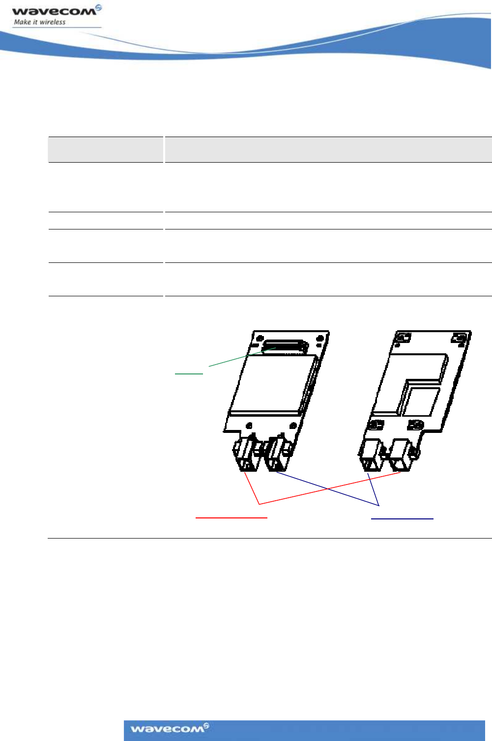
3 Structure of GTM-1 Outline
The outline specifications of the GTM-1 are listed in the following table.
Table 2.
Table 2.Table 2.
Table 2. Dimensions of GTM-1
Item
ItemItem
Item
Description
DescriptionDescription
Description
Printed circuit board
Overall dimensions: 54mm * 105mm
t = 1.6mm +/- 0.1
See 6 for the detail dimension.
CN#1 60 pins board-to-board connector is used.
CN#2
(I/F to CDMA antenna) RF connector is used.
CN#3
(I/F to GPS antenna) RF connector is used.
Outline drawing
(Reference)
CN#3 (GPS)
<Top side> <Under side>
CN#1
CN#2 (CDMA)
GTM-1 User Manual
This document is the sole and exclusive property of WAVECOM.
Page 3 of 9
GTM-1 User Manual
4 Main Features
The main features of the GTM-1 are presented in the table below.
Table 3.
Table 3.Table 3.
Table 3. Main Features of GTM-1
Item
ItemItem
Item
Specification
SpecificationSpecification
Specification
Notes
NotesNotes
Notes
Band Class0 Tx: 824~849 MHz
Rx: 869~894MHz
Frequency Band
Frequency BandFrequency Band
Frequency Band
Band Class1 Tx: 1850~1910 MHz
Rx: 1930~1990MHz
Specifications
SpecificationsSpecifications
Specifications
CDMA2000 1X
IS98-e
Band Class 0 +24dBm (251.12 mW) +/-
1dB
Max Power output
Max Power outputMax Power output
Max Power output
Band Class 1 +24dBm (251.12 mW)
+/-1dB
Supply voltage
Supply voltageSupply voltage
Supply voltage
4V +/-5%
Current
Current Current
Current
consumption
consumptionconsumption
consumption
In
Communication
900mA MAX
Hardware Features
Hardware FeaturesHardware Features
Hardware Features
Autonomous GPS (Not BS assisted)
GPS
Operating
Operating Operating
Operating
temperature
temperaturetemperature
temperature
-30
o
C to +70
o
C Ambient temperature
Storage
Storage Storage
Storage
temperature
temperaturetemperature
temperature
-40
o
C to +85
o
C Ambient temperature
Note: The GTM-1 meets the characteristics described in Table 3 at all temperatures
within the operating temperature range.
GTM-1 User Manual
This document is the sole and exclusive property of WAVECOM.
Page 4 of 9
GTM-1 User Manual
4.1 CDMA Antenna Connector CN#2
The CDMA antenna cable interfaces to connector CN#2.
The maximum allowable antenna system gain in the 850 MHz band is 6.76 dBd.
The maximum allowable antenna system gain in the 850 MHz band is 6.76 dBd.The maximum allowable antenna system gain in the 850 MHz band is 6.76 dBd.
The maximum allowable antenna system gain in the 850 MHz band is 6.76 dBd.
The maximum allowable antenna system gain in the PCS band is 8 dBi.
The maximum allowable antenna system gain in the PCS band is 8 dBi.The maximum allowable antenna system gain in the PCS band is 8 dBi.
The maximum allowable antenna system gain in the PCS band is 8 dBi.
4.2 GPS Antenna Connector CN#3
The GPS antenna cable interfaces to connector CN#3.
The GTM-1 includes a GPS function for the acquisition of vehicle location information.
4.3 GPS Antenna Specification
The GTM-1 GPS Antenna performance is described below.
Item
ItemItem
Item
Description
DescriptionDescription
Description
Frequency 1575.42+/-1.023MHz
Polarization RHCP
Input impedance 50ohm (VSWR =3 or less)
Gain +15 to +30 dBic (= Antenna gain + LNA gain + cable
loss)
Isolation between CDMA
antenna and GPS antenna. 10 dB or more
GTM-1 User Manual
This document is the sole and exclusive property of WAVECOM.
Page 5 of 9
GTM-1 User Manual
5 Operation Specification
5.1 Environmental Condition
The GTM-1, installed in its enclosure, meets the requirements described under the
environmental operating conditions shown in Table 4.
Table 4.
Table 4.Table 4.
Table 4. Environmental Operating Conditions
Item
ItemItem
Item
Rating
RatingRating
Rating
Unit
UnitUnit
Unit
Absolute Maximum Rating 5 V
Ambient Operating temperature -30 to +70 deg. C
Ambient Storage temperature -40 to +85 deg. C
Humidity 95 or less %
5.2 RoHS and VOC Compliance
The GTM-1 is Lead-free, including all components and solder.
The GTM-1 is in compliance with the RoHS (Restriction of Hazardous Substances)
mandate.
The GTM-1 is in compliance with the VOC (Volatile Organic Compounds) mandate.
GTM-1 User Manual
This document is the sole and exclusive property of WAVECOM.
Page 6 of 9
GTM
-
1 User Manual
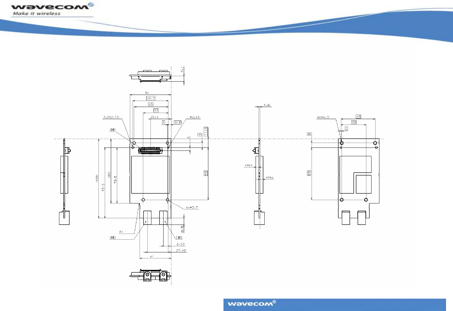
6 Dimension
6.1 GTM-1 Dimensions
GTM-1 User Manual
This document is the sole and exclusive property of WAVECOM.
Page 7 of 9
GTM-1 Operational Description
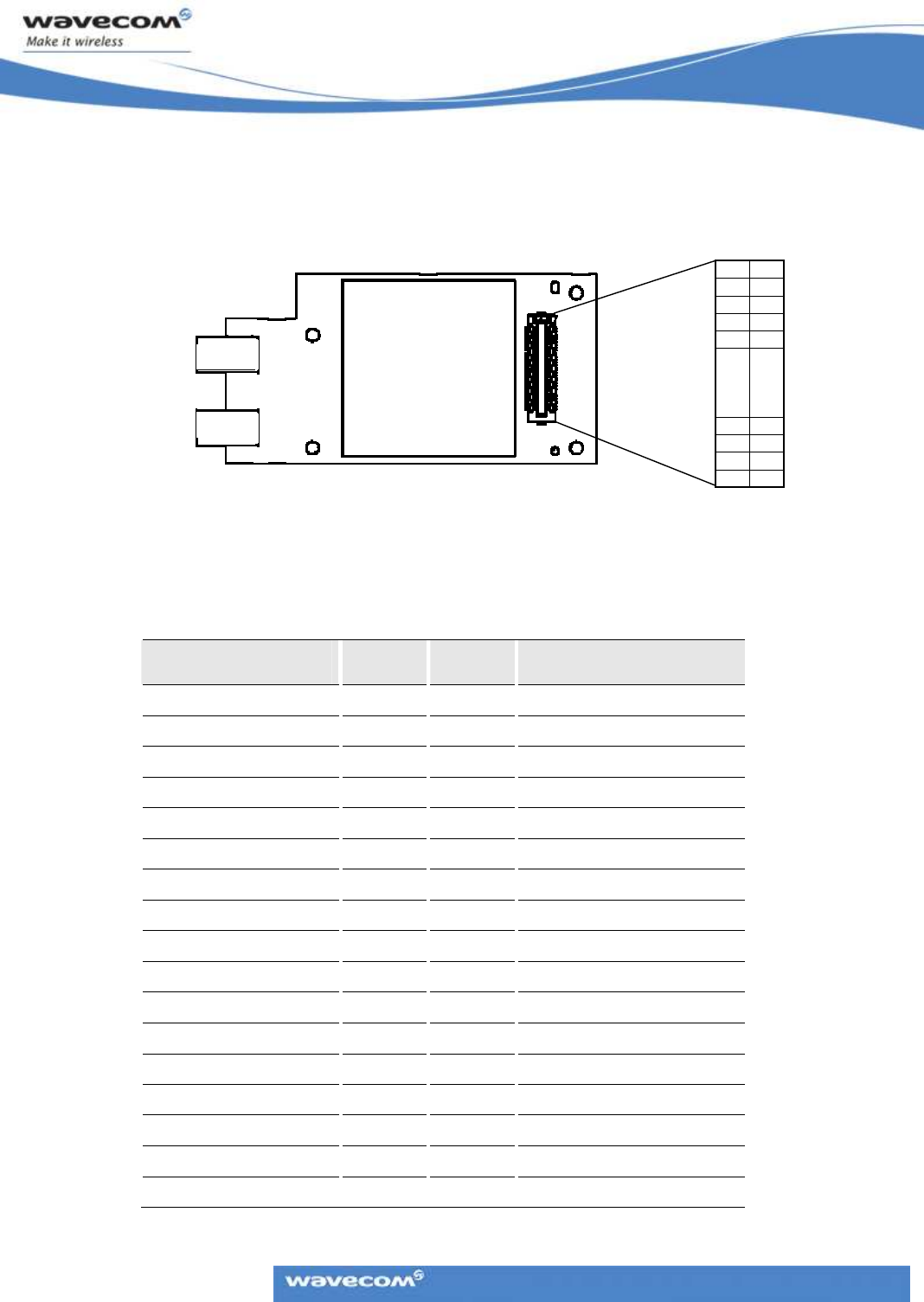
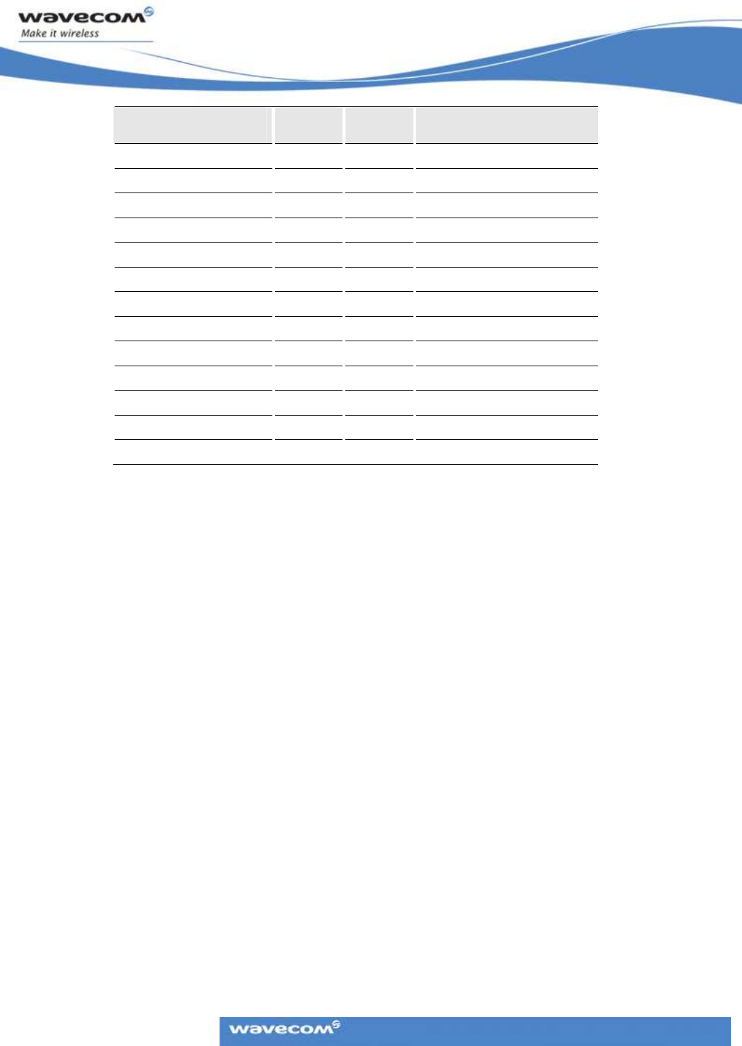
7 Pin Names and Pinout of CN#1
7.1 Pin Arrangement
The table below presents the pin names for each pin as presented in the figure
above.
Table 5.
Table 5.Table 5.
Table 5.
Pins and Corresponding Pin Names
Pin name
Pin namePin name
Pin name
Pin No.
Pin No.Pin No.
Pin No.
Pin No.
Pin No.Pin No.
Pin No.
Pin name
Pin namePin name
Pin name
GND2 2 1 GPO21
SDN1 4 3 IOVCC
GPI18 6 5 RESETX
VCC2 8 7 GPI6
VCC1 10 9 GPO12
GPO25 12 11 GPO14
POWOFF 14 13 GPI5
GPI20 16 15 GPO13
GPO23 18 17 GPI1
GPO11 20 19 GPI0
GPO8 22 21 SUP2
GPI2 24 23 SDN2
RSTCLK 26 25 DAC1
GPI4 28 27 GPI15
GPI3 30 29 AD2
I2CD 32 31 MIC2_N
I2CC 34 33 MIC2_P
5960 5758 5556 5354
……
910 78 56 34 12
5960 5758 5556 5354
……
910 78 56 34 12
Pin No.
GTM-1 User Manual
This document is the sole and exclusive property of WAVECOM.
Page 8 of 9
GTM-1 Operational Description
Pin name
Pin namePin name
Pin name
Pin No.
Pin No.Pin No.
Pin No.
Pin No.
Pin No.Pin No.
Pin No.
Pin name
Pin namePin name
Pin name
GPI7 36 35 GPI22
AD1 38 37 VOR-
SP2_N 40 39 VOR+
SP2_P 42 41 USBG
GPI16 44 43 GPO9
VOT- 46 45 USBV
VOT+ 48 47 GPI24
VOG 50 49 GPI19
GND3 52 51 GND4
USBS1 54 53 GPO21
USB- 56 55 IOVCC
USB+ 58 57 RESETX
USBS2 60 59 GPI6

GTM-1 User Manual
This document is the sole and exclusive property of WAVECOM.
Page 9 of 9
GTM-1 Operational Description
8 FCC Certification
The GTM-1 is FCC certified as a ‘mobile device’, which requires a minimum distance
of 20 cm between the application’s antenna and the human body.
Per FCC Section 15.21, any changes or modifications to the GTM-1 not expressly
approved by Wavecom could void the user's authority to operate the equipment.
Users and installers must be provided with antenna installation instructions and
transmitter operating conditions for satisfying RF exposure compliance.
Wavecom’s FCC ID may be used by the integrator if the following conditions are
followed:
1.
The application must be implemented as a “mobile device” and not a “portable
device.”
2.
The application’s user and installation manuals must include a statement that
a minimum distance of 20 cm between the antenna and the human body is
required.
3.
The antenna system gain must be within the following constraints:
a)
850 MHz Band: the antenna system gain must not exceed 6.76 dBd
gain.
b)
1900 MHz PCS Band: the antenna system gain must not exceed 8 dBi
gain.
4.
The licensed module will have a FCC ID label on the module itself. The FCC ID
label must be visible as defined by the FCC (visible through an open access
door is permissible), or a separate label must be similarly visible that conveys
the message: “Contains Transceiver Module FCC ID: O9EGTM1.”

GTM-1 User Manual
This document is the sole and exclusive property of WAVECOM.
Page 10 of 9
GTM-1 Operational Description
WAVECOM S.A.
-
3 esplanade du Foncet
-
92442 Issy
-
les
-
Moulineaux Cedex
-
France
-
Tel: +33(0)1 46 29 08 00
-
Fax: +33(0)1 46 29 08 08
Wavecom, Inc. - 430 Davis Dr. Suite 300 - Research Triangle Park, NC 27709 - USA - Tel: +1 919 237 4000 - Fax: +1 919 237 4140
WAVECOM Asia Pacific Ltd. - Unit 201-207, 2nd Floor - Bio-Informatics Centre - No. 2 Science Park West Avenue -
Hong Kong Science Park, Shatin
- New Territories, Hong Kong - Tel: +852 2824 0254 - Fax: +852 2824 0255