Sierra Wireless HL6528RD Embedded module User Manual
Sierra Wireless Inc. Embedded module
UserManual.wiki
>
Sierra Wireless
>
HL6528RD User Manual
User manual
Navigation menu
Upload a User Manual
Namespaces
Wiki Guide
HTML
PDF
Info
Views
User Manual
Discussion / Help
Navigation
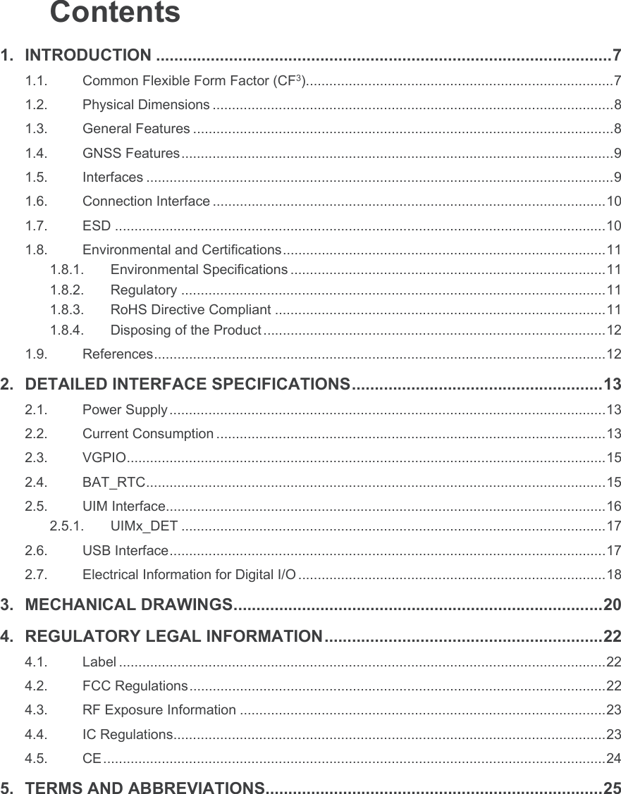
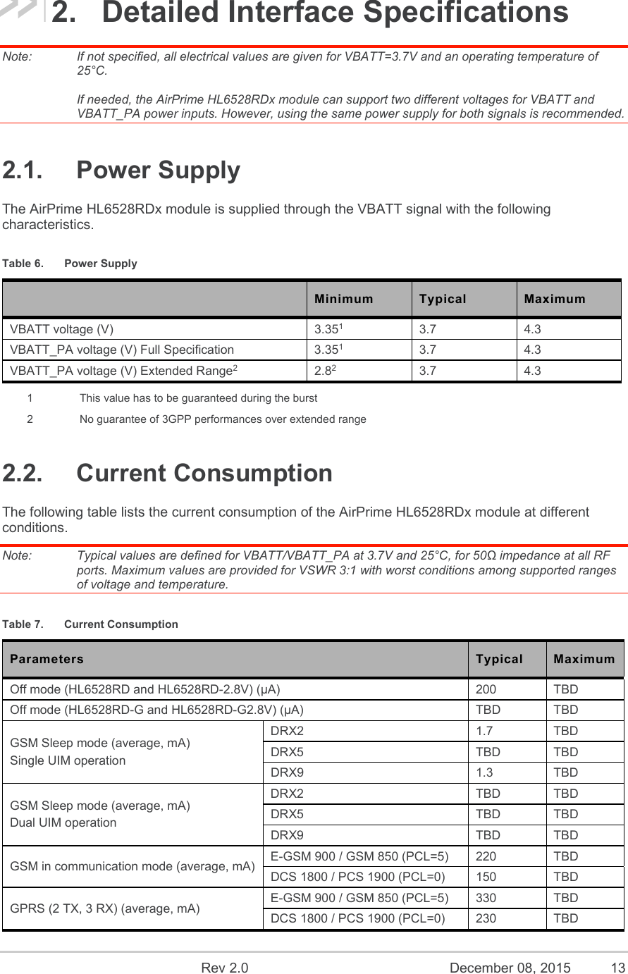
![Product Technical Specification Introduction 1.8.4. Disposing of the Product This electronic product is subject to the EU Directive 2012/19/EU for Waste Electrical and Electronic Equipment (WEEE). As such, this product must not be disposed of at a municipal waste collection point. Please refer to local regulations for directions on how to dispose of this product in an environmental friendly manner. 1.9. References [1] AirPrime HL Series Customer Process Guidelines Reference Number: 4114330 [2] AirPrime HL6528RDx AT Commands Interface Guide Reference Number: 4117743 [3] AirPrime HL Series Development Kit User Guide Reference Number: 4114877](https://usermanual.wiki/Sierra-Wireless/HL6528RD/User-Guide-2846389-Page-12.png)
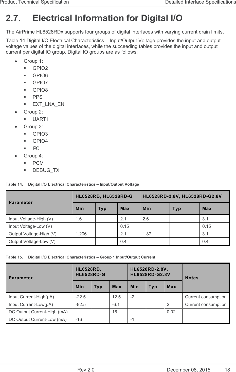
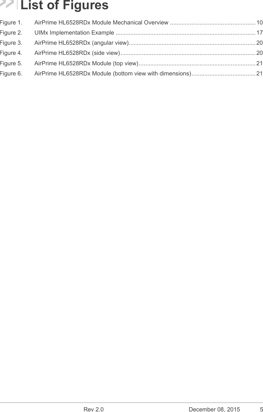
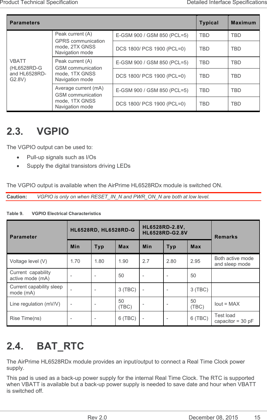
![Rev 2.0 December 08, 2015 14 Product Technical Specification Detailed Interface Specifications Parameters Typical Maximum Peak Current consumption (peak, A) E-GSM 900 / GSM 850 1.5 TBD DCS 1800 / PCS 1900 0.9 TBD GNSS Acquisition1 (average, mA) GSM registered on network Max value3 TBD TBD Min value4 TBD TBD GNSS Acquisition1 (average, mA) GSM in Flight mode Max value3 TBD TBD Min value4 TBD TBD GNSS Navigation (1Hz)1 (average, mA) GSM registered on network Max value3 TBD TBD Min value4 TBD TBD GNSS Navigation (1Hz)1 (average, mA) GSM in Flight mode Max value3 TBD TBD Min value4 TBD TBD GNSS Hibernate mode2 (average, mA) GSM registered on network Max value3 TBD TBD Min value4 TBD TBD 1 Maximum SVs in view, signal level @-130dBm, high gain configuration 2 Hot start conditions are maintained in Hibernate mode 3 Baseband is running (or no sleep mode allowed) in max value condition. Refer to document [2] AirPrime HL6528RDx AT Commands Interface Guide for sleep mode description. 4 Baseband is in sleep mode in min value condition. Refer to document [2] AirPrime HL6528RDx AT Commands Interface Guide for sleep mode description. Table 8. Current Consumption per Power Supply (VBATT / VBATT_PA) Parameters Typical Maximum VBATT_PA Peak current (A) GPRS communication mode, 2TX E-GSM 900 / GSM 850 (PCL=5) TBD TBD DCS 1800/ PCS 1900 (PCL=0) TBD TBD Peak current (A) GSM communication mode, 1TX E-GSM 900 / GSM 850 (PCL=5) TBD TBD DCS 1800/ PCS 1900 (PCL=0) TBD TBD Average current (mA) GSM communication mode, 1TX E-GSM 900 / GSM 850 (PCL=5) TBD TBD DCS 1800/ PCS 1900 (PCL=0) TBD TBD VBATT (HL6528RD and HL6528RD-2.8V) Peak current (A) GPRS communication mode, 2TX E-GSM 900 / GSM 850 (PCL=5) TBD TBD DCS 1800/ PCS 1900 (PCL=0) TBD TBD Peak current (A) GSM communication mode, 1TX E-GSM 900 / GSM 850 (PCL=5) TBD TBD DCS 1800/ PCS 1900 (PCL=0) TBD TBD Average current (mA) GSM communication mode, 1TX E-GSM 900 / GSM 850 (PCL=5) TBD TBD DCS 1800/ PCS 1900 (PCL=0) TBD TBD](https://usermanual.wiki/Sierra-Wireless/HL6528RD/User-Guide-2846389-Page-14.png)
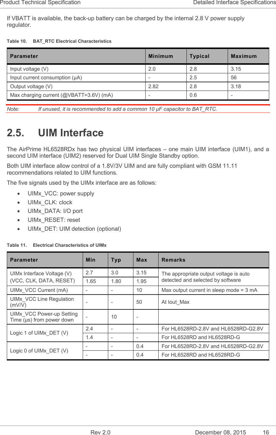
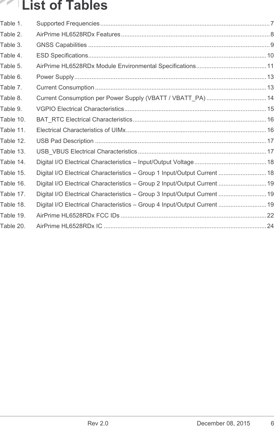
![Rev 2.0 December 08, 2015 17 Product Technical Specification Detailed Interface Specifications Figure 2. UIMx Implementation Example 2.5.1. UIMx_DET UIMx_DET is used to detect and notify the application about the insertion and removal of a UIM device in the UIM socket connected to the UIM interface (UIM1 or UIM2). When a UIM is inserted, the state of UIMx_DET transitions from logic 0 to logic 1. Inversely, when a UIM is removed, the state of UIM1_DET transitions from logic 1 to logic 0. The GPIO used for UIM1_DET is GPIO3, and the GPIO used for UIM2_DET is GPIO4. 2.6. USB Interface The AirPrime HL6528RDx has one USB interface. USB_VBUS is used for USB connection detection purposes. For details, refer to document [2] AirPrime HL6528RDx AT Commands Interface Guide. Table 12. USB Pad Description Pad # Signal Name I/O Function 12 USB_D- I/O USB data negative 13 USB_D+ I/O USB data position 16 USB_VBUS I USB VBUS Table 13. USB_VBUS Electrical Characteristics Parameter Minimum Typical Maximum Unit Input voltage 4.75 5.0 5.25 V Input current consumption - 1 - mA](https://usermanual.wiki/Sierra-Wireless/HL6528RD/User-Guide-2846389-Page-17.png)