Sierra Wireless M1213 GMS/ GPRS Modem User Manual FASTRACK Dual band User Guide
Sierra Wireless, Inc. GMS/ GPRS Modem FASTRACK Dual band User Guide
users manual

Fastrack M1200 series
User Guide
Reference : WM_MKT_Fastrack_UGD_001
Revision : 002
Date : September 2002
confidential © Page : 1 / 29
This document is the sole and exclusive property of WAVECOM. Not to be distributed or divulged without prior written
agreement.
Ce document est la propriété exclusive de WAVECOM. Il ne peut être communiqué ou divulgué à des tiers sans son
autorisation préalable.

WM_MKT_Fastrack_UGD_001 - 002
September 2002
Document Information
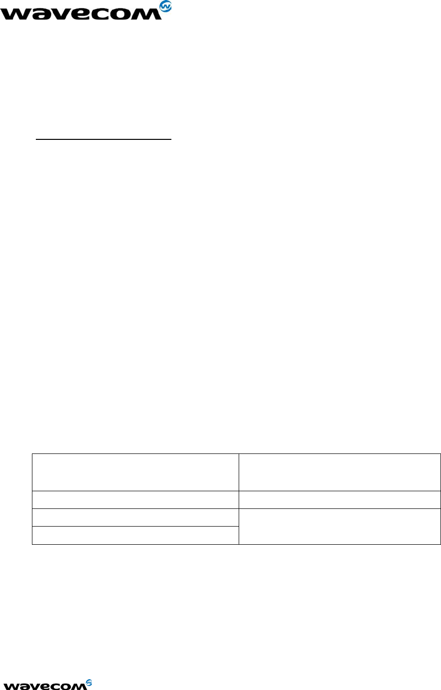
Revision Date History of the evolution
001 June 02 Creation
002 Sept 02 Complete Revision
confidential © Page : 2 / 29
This document is the sole and exclusive property of WAVECOM. Not to be distributed or divulged without prior written
agreement.
Ce document est la propriété exclusive de WAVECOM. Il ne peut être communiqué ou divulgué à des tiers sans son
autorisation préalable.
WM_MKT_Fastrack_UGD_001 - 002
September 2002
Overview
This document describes the hardware interface and the technical specifications of the Fastrack
M1200 series modems:
• M1203 : EGSM/GPRS 900/1800 MHz version.
• M1213 : EGSM/GPRS 900/1900 MHz version.
These products are based on dual-band WISMO module and are GPRS class 2 capable.
WAVECOM® and WISMO® are trademarks or registered trademarks of Wavecom S.A. in France or
in other countries. All other company and/or product names mentioned may be trademarks or
registered trademarks of their respective owners.
WAVECOM S.A. may, at any time and without notice, make changes or improvements to the
products and services offered and/or cease producing or commercializing them.
confidential © Page : 3 / 29
This document is the sole and exclusive property of WAVECOM. Not to be distributed or divulged without prior written
agreement.
Ce document est la propriété exclusive de WAVECOM. Il ne peut être communiqué ou divulgué à des tiers sans son
autorisation préalable.

WM_MKT_Fastrack_UGD_001 - 002
September 2002
Contents
1 Product description ..................................................................................................................................................................7
2 Product details ...........................................................................................................................................................................7
2.1 Physical characteristics ............................................................................................................... 7
2.2 Electrical characteristics .............................................................................................................. 8
2.2.1 Power Consumption ....................................................................................................... 9
2.2.2 Audio interface ............................................................................................................. 10
2.3 GSM features............................................................................................................................. 10
2.4 Hardware interfaces................................................................................................................... 11
2.4.1 Connectors ................................................................................................................... 11
2.4.1.1 SUB-D connector details ...................................................................................... 12
2.4.1.2 Power supply connector ....................................................................................... 12
2.4.2 LED function................................................................................................................. 13
2.4.3 External antenna .......................................................................................................... 13
2.4.4 SIM interface ................................................................................................................ 13
3 Accessories .............................................................................................................................................................................. 14
4 Testing the configuration of Fastrack............................................................................................................................ 15
5 Getting started with Fastrack ........................................................................................................................................... 16
5.1 Mounting Fastrack ..................................................................................................................... 16
5.2 Installing Fastrack modem......................................................................................................... 17
5.3 Verifying signal strength ............................................................................................................ 17
5.4 Verifying network registration of the modem ............................................................................. 18
6 Troubleshooting failed transmission ............................................................................................................................... 19
6.1 Receiving “no carrier” message ............................................................................................... 19
6.2 Not connecting through the serial link ....................................................................................... 21
6.3 Receiving “error” message ........................................................................................................ 22
7 RF exposure instructions.................................................................................................................................................... 24
8 Notice to OEM’s .................................................................................................................................................................... 25
9 NOTES ON SAFETY ............................................................................................................................................................. 26
confidential © Page : 4 / 29
This document is the sole and exclusive property of WAVECOM. Not to be distributed or divulged without prior written
agreement.
Ce document est la propriété exclusive de WAVECOM. Il ne peut être communiqué ou divulgué à des tiers sans son
autorisation préalable.

WM_MKT_Fastrack_UGD_001 - 002
September 2002
9.1 General Safety........................................................................................................................... 26
9.2 Vehicle Safety............................................................................................................................ 27
9.3 Maintenance of GSM modem.................................................................................................... 27
9.4 Your responsibility ..................................................................................................................... 28
10 General information ............................................................................................................................................................... 29
10.1 GSM reference documents .................................................................................................... 29
10.2 ETSI contact ........................................................................................................................... 29
10.3 Service.................................................................................................................................... 29
10.4 Disclaimer............................................................................................................................... 29
10.5 Trademarks ............................................................................................................................ 29
10.6 Copyright ................................................................................................................................ 29
confidential © Page : 5 / 29
This document is the sole and exclusive property of WAVECOM. Not to be distributed or divulged without prior written
agreement.
Ce document est la propriété exclusive de WAVECOM. Il ne peut être communiqué ou divulgué à des tiers sans son
autorisation préalable.

WM_MKT_Fastrack_UGD_001 - 002
September 2002
Tables and Figures
Table 1: Physical characteristics of Fastrack modem .......................................................................... 7
Table 2: Optimal operating and storage temperatures......................................................................... 8
Table 3: Operating voltage ................................................................................................................... 8
Table 4: Effects of power supply defect ............................................................................................... 8
Table 5: Power Consumption ............................................................................................................... 9
Table 6: Audio interface characteristics ............................................................................................. 10
Table 7: Features of Fastrack modem ............................................................................................... 10
Table 8: Fastrack connectors ............................................................................................................. 11
Table 9: Pins assignment for15 pins SUB D Connector .................................................................... 12
Table 10: Pin assignment for Power Supply connector ..................................................................... 13
Table 11: Operational states of Fastrack modem .............................................................................. 13
Table 12: External antenna characteristics ........................................................................................ 13
Table 13: Testing Fastrack configuration ........................................................................................... 15
Table 14: Solutions for “no carrier” message ..................................................................................... 19
Table 15: Interpretation of extended error codes ............................................................................... 20
Table 16: Solutions for no connection through serial link................................................................... 21
Table 17: Solutions for "error" message............................................................................................. 22
Table 18: Interpretation of extended error codes ............................................................................... 23
Figure 1: Fastrack presentation............................................................................................................ 8
Figure 2: Diagram of power supply cable............................................................................................. 9
Figure 3: SMA connector.................................................................................................................... 11
Figure 4: 15 pins SUB D connector (high density) ............................................................................. 12
Figure 5: 4 pins Micro-Fit™ connector ............................................................................................... 12
Figure 6: SIM card holder................................................................................................................... 14
Figure 7: Fastrack mounting............................................................................................................... 16
confidential © Page : 6 / 29
This document is the sole and exclusive property of WAVECOM. Not to be distributed or divulged without prior written
agreement.
Ce document est la propriété exclusive de WAVECOM. Il ne peut être communiqué ou divulgué à des tiers sans son
autorisation préalable.

WM_MKT_Fastrack_UGD_001 - 002
September 2002
1 Product description
The Fastrack modem is small, fast, and efficient. It supports the transmission of:
• data
• fax
• short messages (Point to Point and Cell Broadcast)
• voice calls
The Fastrack modem is a Dual Band product using GSM 900/1800 MHz or GSM 900/1900 MHz and
is GPRS class 2 capable. The basic elements you receive allow simple installation and operation of
the modem. The package includes:
• 1 Fastrack modem M1203 or M1213
• 2 holding bridles
• 1 power supply cable
• 1 fuse
• 1 user guide
2 Product details
2.1 Physical characteristics
The Fastrack modem is small and lightweight. Following table contains information on the physical
characteristics of the Fastrack modem.
Table 1: Physical characteristics of Fastrack modem
Dimensions 98 mm x 54 mm x 25 mm
(excluding connectors)
Overall Dimensions 110 mm x 54 mm x 25 mm
Weight <130 grams
Volume 13.23 cm3
Housing Aluminium
confidential © Page : 7 / 29
This document is the sole and exclusive property of WAVECOM. Not to be distributed or divulged without prior written
agreement.
Ce document est la propriété exclusive de WAVECOM. Il ne peut être communiqué ou divulgué à des tiers sans son
autorisation préalable.
WM_MKT_Fastrack_UGD_001 - 002
September 2002
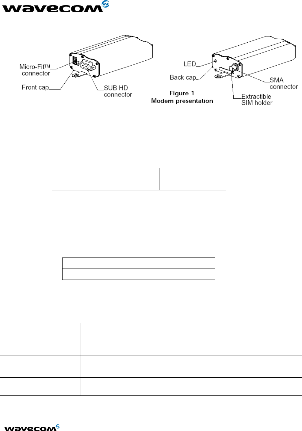
Figure 1: Fastrack presentation
To ensure proper operation of the Fastrack modem, the operating environment must be within a
specific temperature range as described in following table.
Table 2: Optimal operating and storage temperatures
Operating temperature range -20°C to +55°C
Storage temperature range -25°C to +70°C
2.2 Electrical characteristics
The Fastrack modem is permanently ON once you connect the power supply cable to a functional
power supply (see Figure 2). Correct operation of the Fastrack modem is optimum in the following
voltage range:
Table 3: Operating voltage
Operating voltage range: 5 to 32 V
Ground (0V) 0 V
The following table describes the consequences of overvoltage and undervoltage with the Fastrack
modem:
Table 4: Effects of power supply defect
If the voltage: Then the:
falls below 5 V
(undervoltage)
communication is not guaranteed
continuously peaks above
32V (overvoltage)
modem is protected by the fuse
power supply disconnects the electronic components from overvoltage
transiently peaks above 32
V (overvoltage)
modem guarantees its own protection
confidential © Page : 8 / 29
This document is the sole and exclusive property of WAVECOM. Not to be distributed or divulged without prior written
agreement.
Ce document est la propriété exclusive de WAVECOM. Il ne peut être communiqué ou divulgué à des tiers sans son
autorisation préalable.
WM_MKT_Fastrack_UGD_001 - 002
September 2002
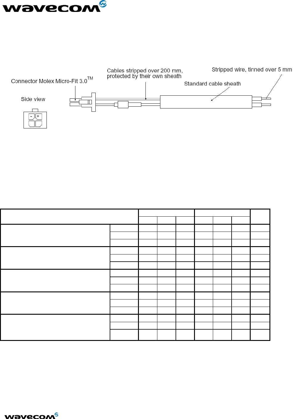
As shown in Figure 2, the power supply cable is a tin copper wire with a:
• core of 24 mm x 0.2 mm
• cross-section of 0.75 mm2
Figure 2: Diagram of power supply cable
2.2.1 Power Consumption
Following table provides information on power consumption of the Fastrack modem, assuming an
operating temperature of +25 °C.
Table 5: Power Consumption
EGSM 900 GSM 1800/1900
Min Typ Max Min Typ Max
Unit
@ 5V 1.74 1.08 A
@ 13.2V 0.73 0.41 A
Input Peak Supply Current
@32V 0.36 0.22 A
@ 5V 330 218 mA
@ 13.2V 130 94 mA
Input average supply current –
communication mode
@32V 65 50 mA
@ 5V 31.4 31.4 mA
@ 13.2V 13.2 13.2 mA
Input average supply current –
idle mode
@32V 5.6 5.6 mA
@ 5V 8.8 8.8 mA
@ 13.2V 4.1 4.1 mA
Input average supply current –
idle mode with RS232 autoshutdown*
@32V 2.2 2.2 mA
@ 5V 5.1 5.1 mA
@ 13.2V 2.5 2.5 mA
Input average supply current –
idle mode with full autoshutdown**
@32V 1.5 1.5 mA
* RS232 driver (MAX3238) automatically shuts down after 30s of inactivity on the serial link.
** RS232 driver in auto-shutdown and AT command
The power consumption might vary by 5% over the whole operating temperature range (-20°C to
+55°C)
The tests are carried out with a 3V SIM card.
confidential © Page : 9 / 29
This document is the sole and exclusive property of WAVECOM. Not to be distributed or divulged without prior written
agreement.
Ce document est la propriété exclusive de WAVECOM. Il ne peut être communiqué ou divulgué à des tiers sans son
autorisation préalable.
WM_MKT_Fastrack_UGD_001 - 002
September 2002
2.2.2 Audio interface
The audio interface is available through the serial and control cable using a headset.
Electrical characteristics of the audio interface are available in the following table.
Table 6: Audio interface characteristics
For GSM 900/1800 and GSM 900/1900 Min Typ Max Unit
Microphone input voltage @ minimum gain 43.8 mVrms
Speaker output voltage @ maximum gain 1.65 Vrms
Speaker Impedance 32 Ω
2.3 GSM features
Fastrack modem is GPRS Class 2 capable. Following table lists the features of the Fastrack
modem.
Table 7: Features of Fastrack modem
MODE DESCRIPTION
Audio Half Rate / Full Rate / Enhanced Full Rate
Accessories (options): handset and car-kit
Standard Dual Band Extended GSM900 MHz
Class 4 (2W) and GSM 1800/1900 MHz Class 1 (1W)
Interface Serial interface RS232 V.24/V.28 Autobauding function
AT command set based on V.25ter and GSM07.05 & 07.07
SMS
Mobile Originated (MO) and Mobile Terminated (MT)
Mode Text & PDU point to point. Cell Broadcast
In accordance with GSM 07.05
Data Asynchronous 2400, 4800, 9600 and 14400 bps.
Transparent and Non Transparent mode
In Non Transparent Mode only: 300, 1200, 1200/75 bauds/
Mode 3.1 KHz (PSTN) and V110 (ISDN)
Fax 2400/4800/7200/9600 bps
GSM teleservice 62 in transparent mode
Class 2
Group 3 compatible
GPRS Class 2
Coding schemes: CS1 to CS4
Compliant with SMG31bis
confidential © Page : 10 / 29
This document is the sole and exclusive property of WAVECOM. Not to be distributed or divulged without prior written
agreement.
Ce document est la propriété exclusive de WAVECOM. Il ne peut être communiqué ou divulgué à des tiers sans son
autorisation préalable.
WM_MKT_Fastrack_UGD_001 - 002
September 2002
2.4 Hardware interfaces
The hardware interfaces which exist for the Fastrack modem include the plugs, sockets, wires and
the electrical pulses traveling through them in a particular pattern.
The Fastrack interfaces include:
• LED function
• External antenna (via SMA)
• Serial and control link (via 15 pins SUB D)
• Power supply (via 4 pins Micro-Fit™)
• SIM interface
2.4.1 Connectors
Refer to the following table for the connectors that exist for the Fastrack modem.
Table 8: Fastrack connectors
Connector Function Refer to
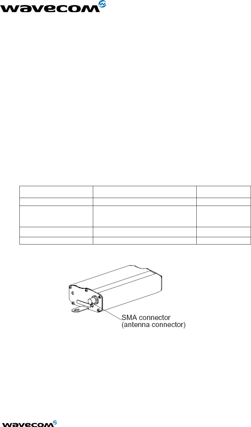
SMA RF antenna connector Figure 3
15 pins SUB D
(high density)
RS232 link
AUDIO link
RESET
Figure 4
4 pins Micro-Fit™ Power supply connector Figure 5
SIM connector SIM card connection Figure 6
Figure 3: SMA connector
confidential © Page : 11 / 29
This document is the sole and exclusive property of WAVECOM. Not to be distributed or divulged without prior written
agreement.
Ce document est la propriété exclusive de WAVECOM. Il ne peut être communiqué ou divulgué à des tiers sans son
autorisation préalable.
WM_MKT_Fastrack_UGD_001 - 002
September 2002
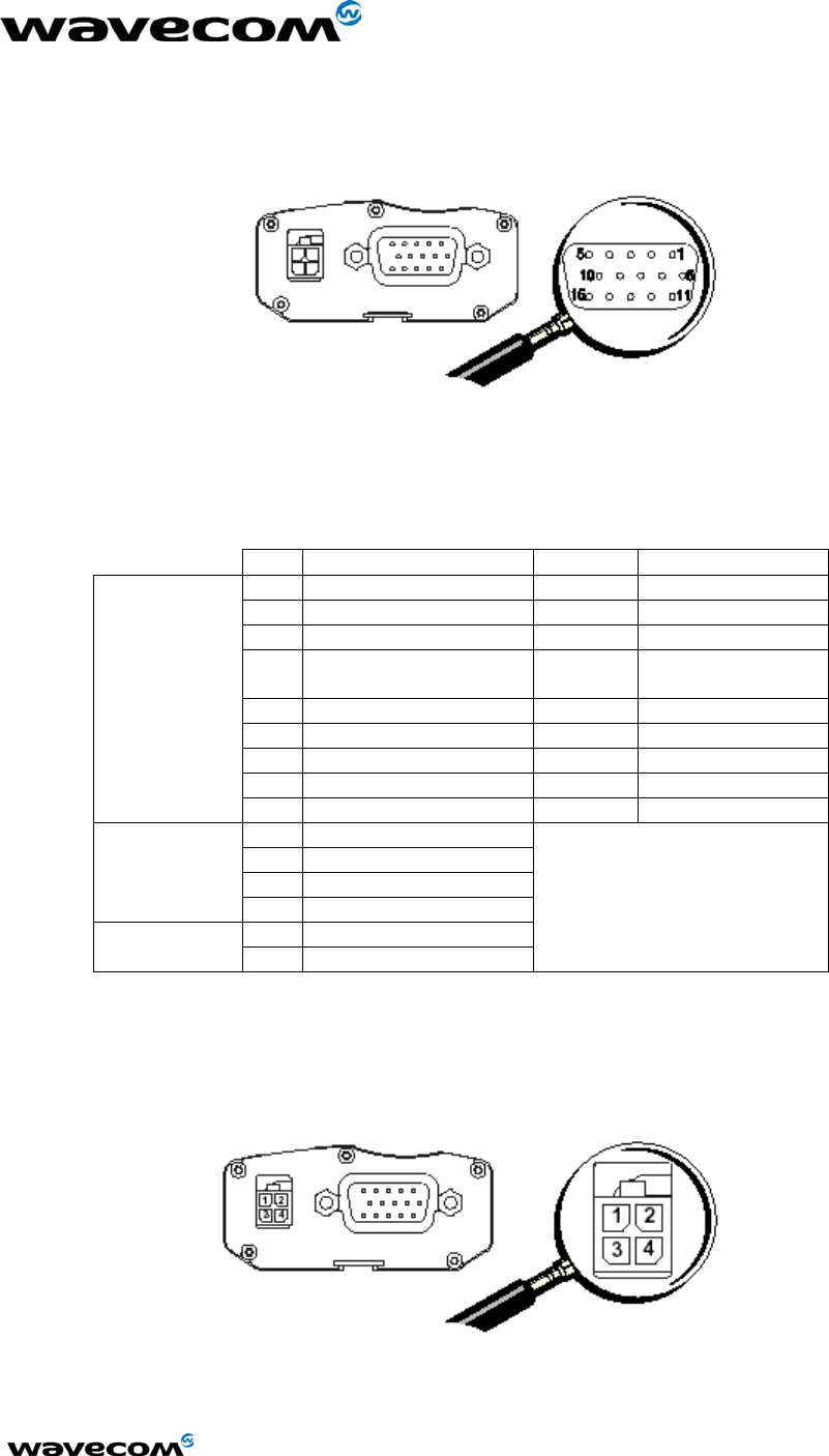
2.4.1.1 SUB-D connector details
Figure 4: 15 pins SUB D connector (high density)
Table 9: Pins assignment for15 pins SUB D Connector
PIN EIA CCIT Designation
1 DCD 109 Data carrier detect
6 RX 104 Receive data
2 TX 103 Transmit data
8 DTR 108.2 Data terminal
ready
9 GND Signal ground
7 DSR 107 Data set ready
12 RTS 105 Request to send
11 CTS 106 Clear to send
RS232
13 RI 125 Ring indicator
4 Microphone (+)
5 Microphone (-)
10 Speaker (+)
Audio
15 Speaker (-)
14 Reset Reset
3 Reserved
Not applicable
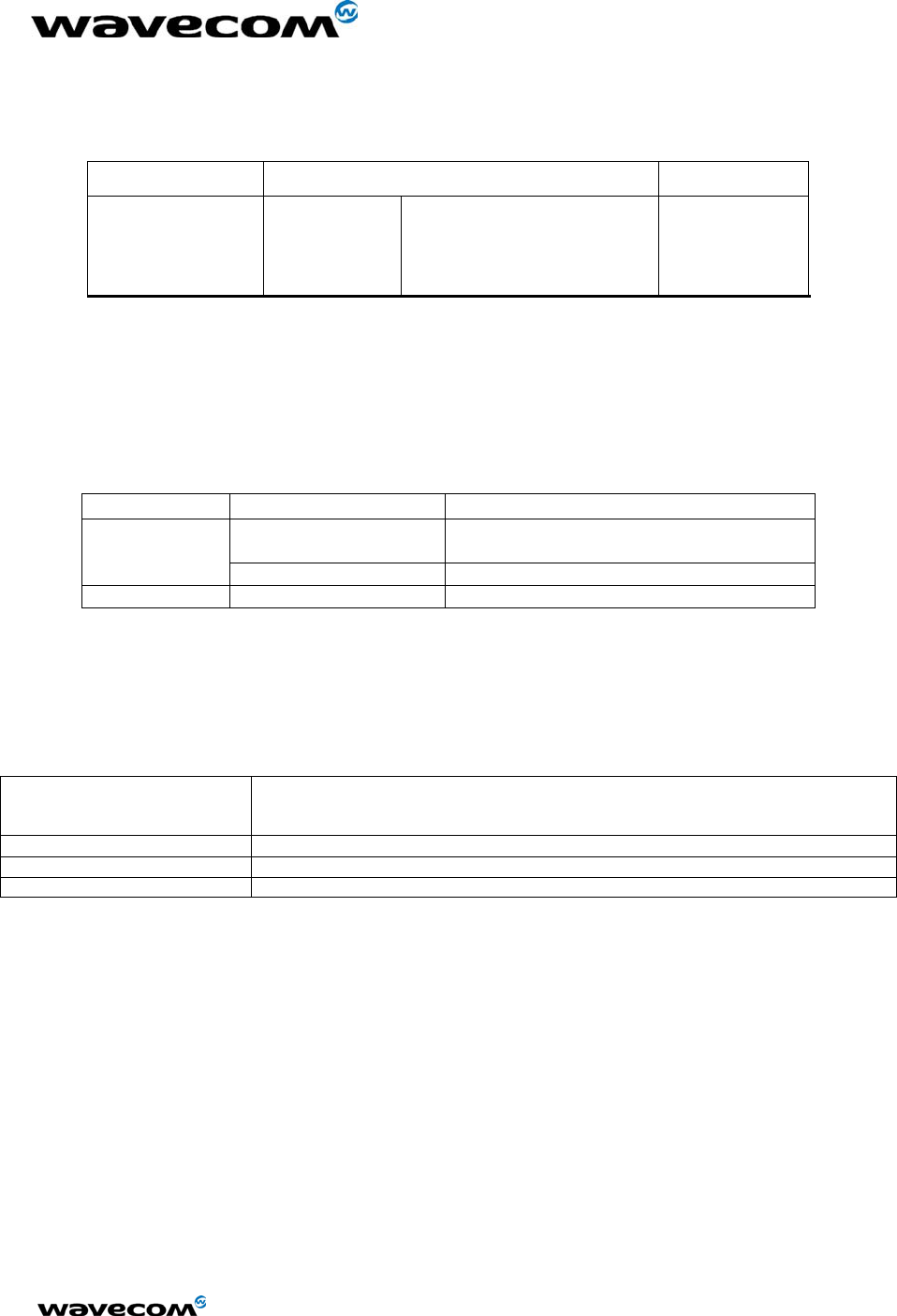
2.4.1.2 Power supply connector
Figure 5: 4 pins Micro-Fit™ connector
confidential © Page : 12 / 29
This document is the sole and exclusive property of WAVECOM. Not to be distributed or divulged without prior written
agreement.
Ce document est la propriété exclusive de WAVECOM. Il ne peut être communiqué ou divulgué à des tiers sans son
autorisation préalable.
WM_MKT_Fastrack_UGD_001 - 002
September 2002
Table 10: Pin assignment for Power Supply connector
Connector Pins layout Comments
4 pins
Micro-Fit 3.0™
1
2
3-4
V+BATTERY
GROUND
AUXI
Power
supply
NC
Order the 4 pins Micro-Fit 3.0™ from the supplier, Molex
2.4.2 LED function
The LED lights indicate the operational status of the modem. Refer to following table for a list of the
LED states.
Table 11: Operational states of Fastrack modem
MODEM is LED light activity Status of MODEM
flashing slowly idle mode
connected to the network
ON
flashing rapidly transmission mode
OFF none not connected to the network
2.4.3 External antenna
The external antenna connects to the modem via the SMA connector. Use an antenna with the
characteristics listed in following table.
Table 12: External antenna characteristics
Antenna frequency range dual band GSM 900/1800 MHz antenna for M1203
or dual band GSM 900/1900 MHz antenna for M1213
or triple band GSM 900/1800/1900 MHz antenna for M1200 series
Impedance 50 Ω
Gain (antenna + cable) 0 dBi
VSWR (antenna + cable) -10 dB
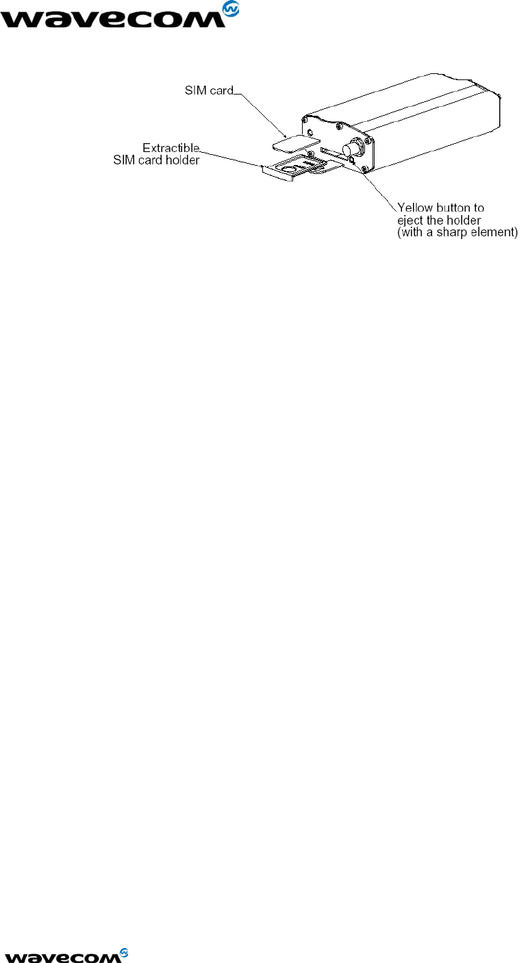
2.4.4 SIM interface
Fastrack modem requires Micro-SIM card and supports 3V and 5V SIM cards. The SIM interface of
the Fastrack modem uses an extractible SIM card holder.
confidential © Page : 13 / 29
This document is the sole and exclusive property of WAVECOM. Not to be distributed or divulged without prior written
agreement.
Ce document est la propriété exclusive de WAVECOM. Il ne peut être communiqué ou divulgué à des tiers sans son
autorisation préalable.
WM_MKT_Fastrack_UGD_001 - 002
September 2002
Figure 6: SIM card holder
3 Accessories
Following accessories are recommended with the Fastrack modem:
• Dual-band antenna: ALLGON 1140.26 (900/1800)
• Dual-Band antenna: ALLGON 1140.27 (900/1900)
• Antenna adaptor: SMA/FME adaptor from PROCOM
• Power adaptor (Europe): EGSTON N2 EFSW 12V 1A mounted with Micro-fit connector from
MOLEX
confidential © Page : 14 / 29
This document is the sole and exclusive property of WAVECOM. Not to be distributed or divulged without prior written
agreement.
Ce document est la propriété exclusive de WAVECOM. Il ne peut être communiqué ou divulgué à des tiers sans son
autorisation préalable.

WM_MKT_Fastrack_UGD_001 - 002
September 2002
4 Testing the configuration of Fastrack
Following table contains AT commands. Use these commands to perform initial tests of the modem
configuration.
Table 13: Testing Fastrack configuration
Task AT commands Module Comments
OK PIN Code accepted
+CME ERROR: 16 Incorrect PIN Code
(with +CMEE = 1 mode)
Enter PIN Code AT+CPIN=1234
+CME ERROR: 3 PIN already entered
(with +CMEE = 1 mode)
CREG=<mode>, 1 Modem synchronized on the
network
CREG=<mode>, 2 Synchronization lost,
resynchronization attempt
Module synchro
checking
AT+CREG ?
CREG=<mode>, 0 Modem not synchronized on the
network, no synchronization attempt
RING Receiving an
incoming call
ATA
OK
Answer the call
Do not forget the « ; » at the end for
voice calls
OK Communication established
CME ERROR: 11 PIN code not entered (with + CMEE
= 1 mode)
Initiate a call
ATD1234;
CME ERROR: 3 AOC credit exceeded or a
communication is already
established
Initiate an
emergency call
ATD112; OK Do not forget the « ; » at the end for
voice calls
Communication
loss
NO CARRIER
Hang up ATH OK
Store the
parameters in
E2P
AT&W OK Configuration settings are stored in
E2P
confidential © Page : 15 / 29
This document is the sole and exclusive property of WAVECOM. Not to be distributed or divulged without prior written
agreement.
Ce document est la propriété exclusive de WAVECOM. Il ne peut être communiqué ou divulgué à des tiers sans son
autorisation préalable.
WM_MKT_Fastrack_UGD_001 - 002
September 2002
5 Getting started with Fastrack
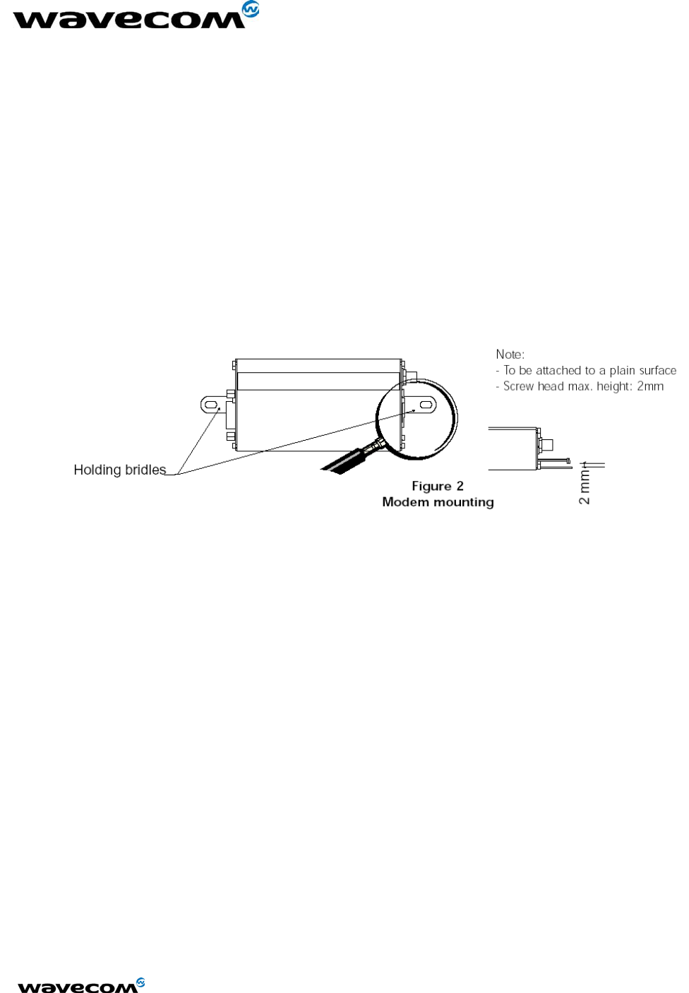
5.1 Mounting Fastrack
To mount the Fastrack modem, do the following:
Place the modem at the desired location on the equipment. 1.
2. Bind the modem to the equipment using the holding bridles. Refer to the following diagram.
Figure 7: Fastrack mounting
confidential © Page : 16 / 29
This document is the sole and exclusive property of WAVECOM. Not to be distributed or divulged without prior written
agreement.
Ce document est la propriété exclusive de WAVECOM. Il ne peut être communiqué ou divulgué à des tiers sans son
autorisation préalable.
WM_MKT_Fastrack_UGD_001 - 002
September 2002
5.2 Installing Fastrack modem
The Fastrack modem requires the power supply connection to begin operation. It also requires a
SIM card to operate on a GSM network. To install the modem, do the following:
1. Connect the power supply cable into the power supply, with a correct GND connection.
Note for automotive application: according to the type of application, you can use permanent
“+” (recommended) or key-switched “+”.
2. Press the SIM card holder ejector (yellow button) with the tip of a pen or use another sharp
object.
3. Insert the SIM card in the holder.
4. Verify that the SIM card fits in the holder properly.
5. Connect the antenna to the SMA connector.
6. Connect both sides of the serial and control cable (15-pin Sub D connector on the modem
side).
7. Activate the power supply
8. Plug the power supply cable into the Fastrack modem.
Note: Refer to Figure 1 for a general presentation of the Fastrack modem. Refer to Figure 6
for insertion of the SIM card.
5.3 Verifying signal strength
The Fastrack modem establishes a call if the signal is sufficiently strong. To verify the signal
strength, do the following:
1. Using the Hyperterminal program, type the AT command AT+CSQ.
Value appears for the received signal strength.
2. Verify the result with the following chart:
Value of signal strength
(AT+CSQ response) (RSSI)
Signal strength
11 – 31 sufficient*
0 – 10
greater than 99
insufficient*
* based on general observations
confidential © Page : 17 / 29
This document is the sole and exclusive property of WAVECOM. Not to be distributed or divulged without prior written
agreement.
Ce document est la propriété exclusive de WAVECOM. Il ne peut être communiqué ou divulgué à des tiers sans son
autorisation préalable.

WM_MKT_Fastrack_UGD_001 - 002
September 2002
5.4 Verifying network registration of the modem
1. Using the Hyperterminal program, type the AT command AT+CREG?.
Value appears for the response.
2. Verify the result with the following chart:
Value Network registration
0,1 Yes
0,5 Yes
(registered roaming)
Note: If the modem is not registered, perform the procedure for 'Verifying signal strength' to
determine the strength of the received signal.
confidential © Page : 18 / 29
This document is the sole and exclusive property of WAVECOM. Not to be distributed or divulged without prior written
agreement.
Ce document est la propriété exclusive de WAVECOM. Il ne peut être communiqué ou divulgué à des tiers sans son
autorisation préalable.

WM_MKT_Fastrack_UGD_001 - 002
September 2002
6 Troubleshooting failed transmission
This section of the document describes possible problems encountered when using the Fastrack
modem and their solutions. To review other troubleshooting information, refer the 'FAQs' (Frequently
Asked Questions) page at www.wavecom.com or use the following link:
http://www.wavecom.com/support/faqs.php
6.1 Receiving “no carrier” message
If the modem returns a message of no carrier upon an attempted transmission of data, or voice
signals, then refer to following table for possible causes and solutions.
Table 14: Solutions for “no carrier” message
If the modem returns … Then ask … Action …
Is the selected bearer type is
supported by the called party?
Is the selected bearer type is
supported by the network?
Type AT+CEER to view the extended
error code (Refer to Table 15)
Ensure that the selected bearer type
is supported by the called party
Ensure that the selected bearer type
is supported by the network
ensure that the semicolon (;) is typed
immediately after the phone number
In the AT command
e.g. ATD######;
type AT+CBST=0,0,3
Configure the SIM card for data/fax
calls
Is the received signal strong
enough?
Refer to § 4 to verify the strength of
the received signal
no carrier
Is the antenna properly
connected?
Refer to Table 12 for antenna
requirements
Refer to the AT commands manual for all codes and details.
confidential © Page : 19 / 29
This document is the sole and exclusive property of WAVECOM. Not to be distributed or divulged without prior written
agreement.
Ce document est la propriété exclusive de WAVECOM. Il ne peut être communiqué ou divulgué à des tiers sans son
autorisation préalable.
WM_MKT_Fastrack_UGD_001 - 002
September 2002
Table 15: Interpretation of extended error codes
Error Code Diagnostic Hint
1 Unallocated phone number
16 Normal call clearing
17 User busy
18 No user responding
19 User alerting, no answer
21 Call rejected
22 Number changed
31 Normal, unspecified
Not applicable
50 Requested facility not
subscribed
Check your subscription (data subscription
available?)
68 ACM equal or greater than
ACMmax
Credit of your pre-paid SIM card expired
252 Call barring on outgoing calls
253 Call barring on incoming calls
Not applicable
3, 6, 8, 29, 34, 38, 41,42,
43, 44, 47, 49, 57, 58, 63,
65, 69, 70, 79, 254
Network causes
Call network provider
See AT commands manual for further details
confidential © Page : 20 / 29
This document is the sole and exclusive property of WAVECOM. Not to be distributed or divulged without prior written
agreement.
Ce document est la propriété exclusive de WAVECOM. Il ne peut être communiqué ou divulgué à des tiers sans son
autorisation préalable.

WM_MKT_Fastrack_UGD_001 - 002
September 2002
6.2 Not connecting through the serial link
If the modem does not answer through the serial link upon an attempted transmission of data, or
voice signals, then refer to following table for possible causes and solutions.
Table 16: Solutions for no connection through serial link
If the modem returns… Then ask… Action…
Is the modem powered
correctly?
Provide a power supply in the range
of 5 to 32 V
Is the serial cable properly
connected to the modem and PC
sockets?
Connect the cable as shown in Figure
4
Verify reception and transmission
Is the communication program
properly configured?
Ensure the following settings for the
modem:
Data bits = 8
Parity = none
Stop bits = 1
Baud = 9600 bps
(nothing)
Is there another program
interfering with the
communication program?
Close the application
e.g. mouse or printer driver
confidential © Page : 21 / 29
This document is the sole and exclusive property of WAVECOM. Not to be distributed or divulged without prior written
agreement.
Ce document est la propriété exclusive de WAVECOM. Il ne peut être communiqué ou divulgué à des tiers sans son
autorisation préalable.

WM_MKT_Fastrack_UGD_001 - 002
September 2002
6.3 Receiving “error” message
If the Fastrack modem returns a message of error upon an attempted transmission of data, or
voice signals, then refer to following table for possible causes and solutions.
Table 17: Solutions for "error" message
If the modem returns… Then ask… Action…
Is the modem registered on the
network?
Refer to § 5.4 to verify that the modem is
registered on the network
Is the modem receiving an incoming
call or is it already in
communication?
End any communication using the ATH
command
Is the selected bearer type is
supported by the called party?
Is the selected bearer type is
supported by the network?
Type AT+CMEE to view the extended error
code
Note: Refer to Table 18
Ensure that the selected bearer type is
supported by the called party
Ensure that the selected bearer type is
supported by the network
Ensure that the semicolon (;) is typed
immediately after the phone number In the
AT command
e.g. ATD######;
Is the received signal strong
enough?
Refer to § 4 to verify the strength of the
received signal
error
Is the antenna properly connected? Refer to Table 12 for antenna
requirements
confidential © Page : 22 / 29
This document is the sole and exclusive property of WAVECOM. Not to be distributed or divulged without prior written
agreement.
Ce document est la propriété exclusive de WAVECOM. Il ne peut être communiqué ou divulgué à des tiers sans son
autorisation préalable.

WM_MKT_Fastrack_UGD_001 - 002
September 2002
Table 18: Interpretation of extended error codes
Error
Code
Diagnostic Hint
0 Phone failure Call technical support
3 Operation not allowed
4 Operation not supported
No action
10 SIM not inserted
Do one of the following:
Insert the SIM card in the SIM holder of the
modem
Check that the SIM card is clean and properly
inserted into the holder
11 SIM PIN required Enter PIN code
12 SIM PUK required Enter PUK code
Note: Call your network provider if you do not
know this code.
13 SIM failure Check validity of your SIM card. If SIM damaged,
call your network provider
16 Incorrect password Check the code you entered
17 SIM PIN2 required Enter PIN2 code
18 SIM PUK2 required Enter PUK2 code
Note: Call your network provider if you do not
know this code.
26 Dialing string too long Check the phone number (max. 20 digits)
30 No network service No action
32 Network not allowed – emergency
calls only
No action
40 Network personalization PIN
required (Network lock)
Enter the Network lock
Note : Call your network provider if you do not
know this code.
103 Illegal MS (#3) No action
106 Illegal ME (#6) No action
107 GPRS services not allowed (#7) Contact your network provider to subscribe to the
GPRS service
111 PLMN not allowed (#11) No action
112 Location area not allowed (#12) No action
113 Roaming not allowed in this location
area (#13)
No action
132 service option not supported (#32) Check the service option
133 requested service option not
subscribed (#33)
Call your network provider to subscribe to the
requested service option
134 service option temporarily out of
order (#34)
No action
149 PDP authentication failure Call your network provider to know the right
authentication parameters
150 invalid mobile class Change the class of the mobile to a valid one
148 unspecified GPRS error No action
confidential © Page : 23 / 29
This document is the sole and exclusive property of WAVECOM. Not to be distributed or divulged without prior written
agreement.
Ce document est la propriété exclusive de WAVECOM. Il ne peut être communiqué ou divulgué à des tiers sans son
autorisation préalable.

WM_MKT_Fastrack_UGD_001 - 002
September 2002
7 RF exposure instructions
Pursuant to 47 CFR § 24.52 of the FCC Rules and Regulations, personnal
communications services (PCS) equipment is subject to the radiofrequency radiation
exposure requirements specified in § 1.1307(b), § 2.1091 and § 2.1093 as approporiate.
The Wavecom Modem is a GSM (PCS 1900) terminal which operates in the US
licensed PCS frequency spectrum. The device transmits over the 1850-1910 MHz band and
receives over the 1930-1990 MHz Band.
Wavecom, Inc. certifies that it has determined that the Modem complies with the RF
hazard requirements applicable to broadband PCS equipment operating under the authority
of 47 CFR Part 24, Subpart E of the FCC Rules and Regulations. This determination is
dependent upon installation, operation and use of the equipment in accordance with all
instructions provided.
The Modem is designed for and intended to be used in fixed and mobile
applications. "Fixed" means that the device is physically secured at one location and is not
able to be easily moved to another location. "Mobile" means that the device is designed to
be used in other than fixed locations and generally in such a way that a separation distance
of at least 20 cm is normally maintained between the transmitter's antenna and the body of
the user or nearby persons. The Modem is not designed for or intended to be used in
portable applications (within 20 cm of the body of the user) and such uses are strictly
prohibited.
To ensure that the unit complies with current FCC regulations limiting both maximum
RF output power and human exposure to radiofrequency radiation, a separation distance of
at least 20 cm must be maintained between the unit's antenna and the body of the user and
any nearby persons at all times and in all applications and uses. Additionally, in mobile
applications, maximum antenna gain must not exceed 3 dBi (to comply with Section
24.232(b) and is limited to 7 dBi for fixed applications. Finally, the tune-up procedure for the
O9EM1213 ensures that the maximum RF output power of the device does not exceed
29.38 dBm within the variations that can be expected due to quantity production and testing
on a statistical basis.
confidential © Page : 24 / 29
This document is the sole and exclusive property of WAVECOM. Not to be distributed or divulged without prior written
agreement.
Ce document est la propriété exclusive de WAVECOM. Il ne peut être communiqué ou divulgué à des tiers sans son
autorisation préalable.

WM_MKT_Fastrack_UGD_001 - 002
September 2002
8 Notice to OEM’s
A minimum separation of 20 cm must be maintained between the antenna and persons for
this device to satisfy the RF exposure requirement of the FCC. For fixed mount operation, the
antenna co-location requirements of section 1.1307(b)(3) of the FCC rules must be satisfied. For
fixed mount operation, the maximum gain of the antenna must not exceed 7 dBi. For mobile
operation, the maximum gain of the antenna must not exceed 3 dBi.
WARNING! Use of this module in portable operations is not permitted.
Wavecom User’s manual includes specific warnings and cautions in order to ensure that
OEMs are aware of their responsibilities, with regards to RF exposure compliance, for products into
which the modem is integrated. With this guidance, the OEM will be able to incorporate into their
documentation the necessary operating conditions and warnings.
OEMs need to provide a manual with the ‘’final’’ product that clearly states the operating
requirements and conditions and that these must be observed to ensure compliance with current
FCC RF exposure requirements / MPE limits (refer to chapter 7. RF exposure instructions). This will
enable the OEM to generate (and provide the end-user with) the appropriate operating instructions,
warnings and cautions, and/or markings for their product.
Licensed module must have an FCC ID label on the module itself. That FCC ID label must be
visible through a window on the final device or it must be visible when an access panel, door or
cover is easily removed. If not, a second label must be placed on the outside of the final
device that contains the following text: "Contains FCC ID: O9EM1213”
Grant Notes:
Modular transmitter. Power listed is conducted. This device is to be used only for mobile and
fixed applications. The antenna(s) used for this transmitter must be installed to provide a separation
distance of at least 20cm from all persons and must not be co-located or operating in conjunction
with any other antenna or transmitter. The antenna(s) used for this transmitter must not exceed a
gain of 3dBi for mobile operation and 7dBi for fixed operation. Users and OEM integrators must be
provided with antenna installation instructions and transmitter operating conditions for satisfying RF
exposure compliance. OEM must also be provided with labeling instructions. This device contains
900 MHz GSM functions that are not operational in U.S. Territories. This filing is only applicable for
900 MHz PCS operations.
confidential © Page : 25 / 29
This document is the sole and exclusive property of WAVECOM. Not to be distributed or divulged without prior written
agreement.
Ce document est la propriété exclusive de WAVECOM. Il ne peut être communiqué ou divulgué à des tiers sans son
autorisation préalable.

WM_MKT_Fastrack_UGD_001 - 002
September 2002
9 NOTES ON SAFETY
9.1 General Safety
It is important to follow any special regulations regarding the use of radio equipment due to the
possibility of radio frequency, RF, interference. Please carefully follow the safety advice given below:
• Switch OFF your GSM Modem when in an aircraft. The use of cellular telephones in an aircraft
may endanger the operation of the aircraft, disrupt the cellular network and is illegal. Failure to
observe this instruction may lead to suspension or denial of cellular telephone services to the
offender, or legal action or both.
• Switch OFF your GSM Modem when at a refueling point.
• Switch OFF your GSM Modem in hospitals and any other place where medical equipment may
be in use.
• Respect restrictions on the use of radio equipment in fuel depots, chemical plants or where
blasting operations are in progress.
• There may be a hazard associated with the operation of your GSM Modem close to
inadequately protected personal medical devices such as hearing aids and pacemakers. Consult
the manufacturers of the medical device to determine if it is adequately protected.
• Operation of your GSM Modem close to other electronic equipment may also cause interference
if the equipment is inadequately protected. Observe any warning signs and manufacturers
recommendations.
The modem is designed for and intended to be used in fixed and mobile applications.
Fixed means that the device is physically secured at one location and is not able to be easily moved
to another location.
Mobile means that the device is designed to be used in other than fixed locations and generally in
such a way that a separation distance of at least 20 cm (8 inches) is normally maintained between
the transmitter’s antenna and the body of the user or nearby persons.
The Modem is not designed for or intended to be used in portable applications (within 20cm of the
body of the user) and such uses are strictly prohibited.
confidential © Page : 26 / 29
This document is the sole and exclusive property of WAVECOM. Not to be distributed or divulged without prior written
agreement.
Ce document est la propriété exclusive de WAVECOM. Il ne peut être communiqué ou divulgué à des tiers sans son
autorisation préalable.

WM_MKT_Fastrack_UGD_001 - 002
September 2002
9.2 Vehicle Safety
Follow these guidelines for use of the modem in an automobile:
• Do not use your GSM Modem while driving, unless equipped with a correctly installed vehicle kit
allowing ’Hands-Free’ Operation.
• Respect national regulations on the use of cellular telephones in vehicles. Road safety always
comes first.
• If incorrectly installed in a vehicle, the operation of GSM Modem telephone could interfere with
the correct functioning of vehicle electronics. To avoid such problems, ensure that the
installation has been performed y a qualified personnel. Verification of the protection of vehicle
electronics should form part of the installation.
• The use of an alert device to operate a vehicle’s lights or horn on public roads is not permitted.
9.3 Maintenance of GSM modem
Your GSM Modem is the product of advanced engineering, design and craftsmanship and should be
treated with care. The suggestions below will help you to enjoy this product for many years.
• Do not expose the GSM Modem to any extreme environment where the temperature or humidity
is high.
• Do not attempt to disassemble the GSM Modem. There are no user serviceable parts inside.
• Do not expose the GSM Modem to water, rain or spilt beverages, It is not waterproof.
• Do not abuse your GSM Modem by dropping, knocking, or violent shaking. Rough handling can
damage it.
• Do not place the GSM Modem alongside computer discs, credit or travel cards or other magnetic
media. The information contained on discs or cards may be affected by the phone.
• The use of third party equipment or accessories, not made or authorized by Wavecom may
invalidate the warranty of GSM Modem.
• Do contact an authorized Service Center in the unlikely event of a fault.
confidential © Page : 27 / 29
This document is the sole and exclusive property of WAVECOM. Not to be distributed or divulged without prior written
agreement.
Ce document est la propriété exclusive de WAVECOM. Il ne peut être communiqué ou divulgué à des tiers sans son
autorisation préalable.

WM_MKT_Fastrack_UGD_001 - 002
September 2002
9.4 Your responsibility
This GSM Modem is under your responsibility. Please treat it with care respecting all local
regulations. It is not a toy
Therefore, keep it in a safe place at all times and out of the reach of children.
Remember your Unlock and PIN codes. Become familiar with and use the security features to block
unauthorized use and theft.
confidential © Page : 28 / 29
This document is the sole and exclusive property of WAVECOM. Not to be distributed or divulged without prior written
agreement.
Ce document est la propriété exclusive de WAVECOM. Il ne peut être communiqué ou divulgué à des tiers sans son
autorisation préalable.

WM_MKT_Fastrack_UGD_001 - 002
September 2002
confidential © Page : 29 / 29
This document is the sole and exclusive property of WAVECOM. Not to be distributed or divulged without prior written
agreement.
Ce document est la propriété exclusive de WAVECOM. Il ne peut être communiqué ou divulgué à des tiers sans son
autorisation préalable.
10 General information
10.1 GSM reference documents
GSM 03.40, GSM 03.45, GSM 04.11,
GSM 04.21, GSM 05.08, GSM 07.01,
GSM 07.02, GSM 07.05, GSM 07.07.
10.2 ETSI contact
ETSI Secretariat
F-06921 Sophia Antipolis Cedex, France
e-mail: secretariat@etsi.fr
10.3 Service
The AT commands manual is available from your local modem supplier.
10.4 Disclaimer
Modem and GSM-unit specifications and manuals are subject to change without notice. Wavecom
assumes no liability for damage incurred directly or indirectly from errors, omissions or discrepancies
between the modem or GSM-unit and their manuals.
10.5 Trademarks
Some mentioned products are registered trademarks of them respective companies.
10.6 Copyright
This manual is copyrighted by Wavecom with all rights reserved. No part of this manual may be
reproduced in any form without the prior written permission of Wavecom.
No patent liability is assumed with respect to the use of the information contained herein.