Sierra Wireless MC7354B Cellular/PCS GSM/WCDMA/LTE Modem User Manual AirPrime MC7354B Hardware Integration Guide
Sierra Wireless Inc. Cellular/PCS GSM/WCDMA/LTE Modem AirPrime MC7354B Hardware Integration Guide
AirPrime - MC7354B - Hardware Integration Guide - Rev1.0

4117529
1.0
June 12, 2015
AirPrime MC7354B
Hardware Integration Guide

4117529 Rev 1.0 June 12, 2015 2
Hardware Integration Guide
Important Notice
Due to the nature of wireless communications, transmission and reception of data can never be
guaranteed. Data may be delayed, corrupted (i.e., have errors) or be totally lost. Although significant
delays or losses of data are rare when wireless devices such as the Sierra Wireless modem are used
in a normal manner with a well-constructed network, the Sierra Wireless modem should not be used
in situations where failure to transmit or receive data could result in damage of any kind to the user or
any other party, including but not limited to personal injury, death, or loss of property. Sierra Wireless
accepts no responsibility for damages of any kind resulting from delays or errors in data transmitted or
received using the Sierra Wireless modem, or for failure of the Sierra Wireless modem to transmit or
receive such data.
Safety and Hazards
Do not operate the Sierra Wireless modem in areas where cellular modems are not advised without
proper device certifications. These areas include environments where cellular radio can interfere such
as explosive atmospheres, medical equipment, or any other equipment which may be susceptible to
any form of radio interference. The Sierra Wireless modem can transmit signals that could interfere
with this equipment. Do not operate the Sierra Wireless modem in any aircraft, whether the aircraft is
on the ground or in flight. In aircraft, the Sierra Wireless modem MUST BE POWERED OFF. When
operating, the Sierra Wireless modem can transmit signals that could interfere with various onboard
systems.
Note: Some airlines may permit the use of cellular phones while the aircraft is on the ground and the door
is open. Sierra Wireless modems may be used at this time.
The driver or operator of any vehicle should not operate the Sierra Wireless modem while in control of
a vehicle. Doing so will detract from the driver or operator’s control and operation of that vehicle. In
some states and provinces, operating such communications devices while in control of a vehicle is an
offence.
Limitations of Liability
This manual is provided “as is”. Sierra Wireless makes no warranties of any kind, either expressed or
implied, including any implied warranties of merchantability, fitness for a particular purpose, or
noninfringement. The recipient of the manual shall endorse all risks arising from its use.
The information in this manual is subject to change without notice and does not represent a
commitment on the part of Sierra Wireless. SIERRA WIRELESS AND ITS AFFILIATES
SPECIFICALLY DISCLAIM LIABILITY FOR ANY AND ALL DIRECT, INDIRECT, SPECIAL,
GENERAL, INCIDENTAL, CONSEQUENTIAL, PUNITIVE OR EXEMPLARY DAMAGES INCLUDING,
BUT NOT LIMITED TO, LOSS OF PROFITS OR REVENUE OR ANTICIPATED PROFITS OR
REVENUE ARISING OUT OF THE USE OR INABILITY TO USE ANY SIERRA WIRELESS
PRODUCT, EVEN IF SIERRA WIRELESS AND/OR ITS AFFILIATES HAS BEEN ADVISED OF THE
POSSIBILITY OF SUCH DAMAGES OR THEY ARE FORESEEABLE OR FOR CLAIMS BY ANY
THIRD PARTY.
Notwithstanding the foregoing, in no event shall Sierra Wireless and/or its affiliates aggregate liability
arising under or in connection with the Sierra Wireless product, regardless of the number of events,
occurrences, or claims giving rise to liability, be in excess of the price paid by the purchaser for the
Sierra Wireless product.
Customer understands that Sierra Wireless is not providing cellular or GPS (including A-GPS)
services. These services are provided by a third party and should be purchased directly by the
Customer.

4117529 Rev 1.0 June 12, 2015 3
Hardware Integration Guide
SPECIFIC DISCLAIMERS OF LIABILITY: CUSTOMER RECOGNIZES AND ACKNOWLEDGES
SIERRA WIRELESS IS NOT RESPONSIBLE FOR AND SHALL NOT BE HELD LIABLE FOR ANY
DEFECT OR DEFICIENCY OF ANY KIND OF CELLULAR OR GPS (INCLUDING A-GPS)
SERVICES.
Patents
This product may contain technology developed by or for Sierra Wireless Inc.
This product includes technology licensed from QUALCOMM®.
This product is manufactured or sold by Sierra Wireless Inc. or its affiliates under one or more patents
licensed from InterDigital Group and MMP Portfolio Licensing.
Copyright
© 2015 Sierra Wireless. All rights reserved.
Trademarks
Sierra Wireless®, AirPrime®, AirLink®, AirVantage®, WISMO®, ALEOS® and the Sierra Wireless and
Open AT logos are registered trademarks of Sierra Wireless, Inc. or one of its subsidiaries.
Watcher® is a registered trademark of NETGEAR, Inc., used under license.
Windows® and Windows Vista® are registered trademarks of Microsoft Corporation.
Macintosh® and Mac OS X® are registered trademarks of Apple Inc., registered in the U.S. and other
countries.
QUALCOMM® is a registered trademark of QUALCOMM Incorporated. Used under license.
Other trademarks are the property of their respective owners.
Contact Information
Sales Desk:
Phone:
1-604-232-1488
Hours:
8:00 AM to 5:00 PM Pacific Time
Contact:
http://www.sierrawireless.com/sales
Post:
Sierra Wireless
13811 Wireless Way
Richmond, BC
Canada V6V 3A4
Technical Support:
support@sierrawireless.com
RMA Support:
repairs@sierrawireless.com
Fax:
1-604-231-1109
Web:
http://www.sierrawireless.com/
Consult our website for up-to-date product descriptions, documentation, application notes, firmware
upgrades, troubleshooting tips, and press releases: www.sierrawireless.com

4117529 Rev 1.0 June 12, 2015 4
Hardware Integration Guide
Document History
Version
Date
Updates
1.0
June 12, 2015
Creation

4117529 Rev 1.0 June 12, 2015 5
Contents
1. INTRODUCTION .................................................................................................. 7
1.1. Hardware Development Components ............................................................................... 7
2. POWER INTERFACE ........................................................................................... 8
2.1. Power Supply .................................................................................................................... 8
2.2. Electrostatic Discharge (ESD) ........................................................................................... 8
2.3. Power States ..................................................................................................................... 9
3. RF INTEGRATION ............................................................................................. 10
3.1. Supported RF Bands ....................................................................................................... 10
3.2. Ground Connection ......................................................................................................... 11
3.3. Shielding Guidelines ........................................................................................................ 11
3.4. Antenna Guidelines ......................................................................................................... 11
3.4.1. Choosing the Correct Antenna and Cabling ............................................................ 11
3.4.2. Determining the Antenna’s Location ........................................................................ 11
3.5. RF Desense Sources ...................................................................................................... 12
4. AUDIO INTERFACE ........................................................................................... 13
5. REGULATORY INFORMATION......................................................................... 14
5.1. Important Notice .............................................................................................................. 14
5.2. Safety and Hazards ......................................................................................................... 14
5.3. Important Compliance Information for North American Users ........................................ 15
6. REFERENCES ................................................................................................... 17
6.1. Reference Documents ..................................................................................................... 17
6.2. List of Abbreviations ........................................................................................................ 17

4117529 Rev 1.0 June 12, 2015 6
List of Tables
Table 1. Power Supply Requirements ............................................................................................. 8
Table 2. ESD Specifications ............................................................................................................ 8
Table 3. Supported MC7354B Power States .................................................................................. 9
Table 4. Supported RF Bands ....................................................................................................... 10
Table 5. Audio Pin Description ...................................................................................................... 13

4117529 Rev 1.0 June 12, 2015 7
1. Introduction
The Sierra Wireless AirPrime MC7354B PCI Express Mini Card is a compact, lightweight, wireless
LTE-, UMTS-, CDMA- and GSM-based modem.
It provides LTE, EVDO Rel 0, EVDO Rel A, DC-HSPA+, HSPA+, HSDPA, HSUPA, WCDMA, GSM,
GPRS, EDGE and GNSS connectivity for networking, and M2M applications over several radio
frequency bands. The device also supports 2G/3G roaming, subject to carrier provisioning.
1.1. Hardware Development Components
Sierra Wireless manufactures the MC Series Development Kit, a hardware development component
that is used to facilitate the hardware integration process. This development kit is the hardware
development board on which an MC mini card is plugged. The development kit provides access to all
of the interfaces supported by the MC mini card.
For instructions on using the MC Development Kit, see document [2] AirPrime MC Series
Development Kit Quick Start Guide.
4117529 Rev 1.0 June 12, 2015 8
2. Power Interface
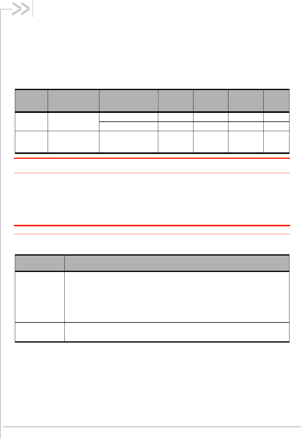
2.1. Power Supply
The host device must provide power to the MC7354B mini card over pins 2, 24, 39, 41 and 52 (VCC)
as detailed in the following table.
Table 1. Power Supply Requirements
Signal
Name
Pin
Specification
Minimum
Typical
Maximum
Unit
VCC
2, 24, 39, 41, 52
Voltage range
3.0
3.3
3.6
V
Ripple voltage
-
-
100
mVpp
GND
4, 9, 15, 18, 21,
26, 27, 29, 34, 35,
37, 40, 43, 50
-
-
0
-
V
Note: The host must provide safe and continuous power at all times; the module does not have an
independent power supply, or protection circuits to guard against electrical issues.
2.2. Electrostatic Discharge (ESD)
The OEM is responsible for ensuring that the Mini Card host interface pins are not exposed to ESD
during handling or normal operation.
Note: The level of protection required depends on your application.
Table 2. ESD Specifications
Connection
Specification
Operational
The RF port (antenna launch and RF connector) complies with the IEC 61000-4-2
standard:
Electrostatic Discharge Immunity:
Test: Level3
Contact Discharge: ±6 kV
Air Discharge: ±8 kV
Non-operational
The host connector Interface complies with the following standard only:
±2 kV Human Body Model (JESD22-A114-B)

4117529 Rev 1.0 June 12, 2015 9
Hardware Integration Guide
Power Interface
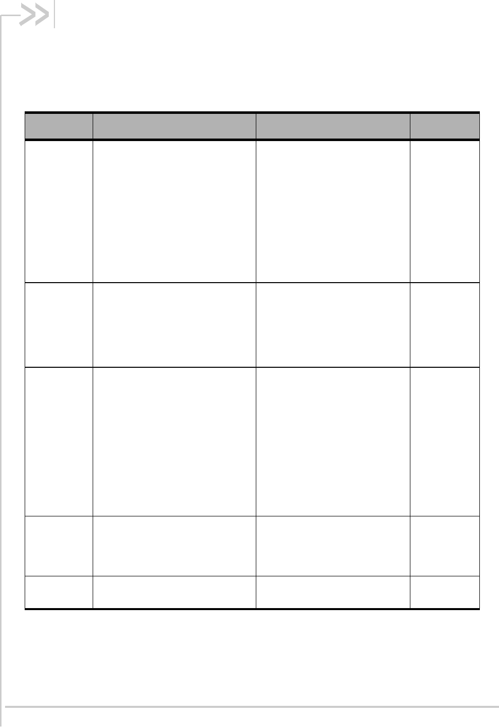
2.3. Power States
The MC7354B mini card has four power states as detailed in the following table.
Table 3. Supported MC7354B Power States
State
Details
Host is
Powered
Module is
Powered
USB
Interface
Active
RF
Enabled
Normal
(Default
state)
Module is active
Default state when VCC is
first applied in the absence of
W_DISABLE_N control
Module is capable of placing /
receiving calls, or establishing
data connections on the
wireless network
Current consumption is
affected by several factors,
including:
Radio band being used
Transmit power
Receive gain settings
Data rate
Number of active Tx time slots
Low power
(‘Airplane
mode’)
Module is active
Module enters this state:
Under host interface control:
Host issues AT+CFUN=0,
or
Host asserts
W_DISABLE_N, after
AT!PCOFFEN=0 has
been issued.
Automatically, when critical
temperature or voltage trigger
limits have been reached
Sleep
Normal state of module
between calls or data
connections
Module cycles between wake
(polling the network) and
sleep, at network provider-
determined interval.
Disconnected
Host power source is disconnected
from the module and all voltages
associated with the module are at 0 V.
4117529 Rev 1.0 June 12, 2015 10
3. RF Integration
3.1. Supported RF Bands
Table 4. Supported RF Bands
Technology
Bands
Data Rates
Notes
LTE
Band 2 (1900 MHz)
Band 4 (AWS)
(1700/2100 MHz)
Band 5 (850 MHz)
Band 13 (700 MHz)
Band 17 (700 MHz)
Band 25 (1900 MHz)
Band 26 (850 MHz)
Category 3
Downlink:
100 Mbps
(20 MHz bandwidth)
50 Mbps
(10 MHz bandwidth)
Uplink:
50 Mbps
(20 MHz bandwidth)
25 Mbps
(10 MHz bandwidth)
MIMO support
UMTS
(WCDMA)
HSDPA
HSUPA
HSPA+
DC-HSPA+
Band 1 (2100 MHz)
Band 2 (1900 MHz)
Band 4 (AWS)
(1700/2100 MHz)
Band 5 (850 MHz)
Band 8 (900 MHz)
HSPA+ rates:
Downlink: Up to 42 Mbps
(category 24)
Uplink: Up to 5.76 Mbps
(category 6)
Diversity
support
CDMA
EVDO Rel 0
EVDO Rel A
BC0 (Cellular 800 MHz)
BC1 (PCS 1900 MHz)
BC10 (Secondary 800 MHz)
CDMA IS-856
(1xEV-DO Release A)
Up to 3.1 Mbps
forward channel
Up to 1.8 Mbps
reverse channel
CDMA IS-2000
Up to 153 kbps,
simultaneous forward
and reverse channel
Circuit-switched data
bearers up to 14.4 kbps
Diversity
support
GSM
GPRS
EDGE
GSM 850 (850 MHz)
GSM 900 (900 MHz)
DCS 1800 (1800 MHz)
PCS 1900 (1900 MHz)
EDGE
throughput up
to 236 kbps
GNSS
GPS: 1575.42 MHz
GLONASS: 1602 MHz

4117529 Rev 1.0 June 12, 2015 11
Hardware Integration Guide
RF Integration
3.2. Ground Connection
When connecting the mini card to system ground:
Prevent noise leakage by establishing a very good ground connection to the mini card
through the host connector.
Minimize ground noise leakage into the RF. Depending on the host board design, noise could
potentially be coupled to the mini card from the host board. This is mainly an issue for host
designs that have signals traveling along the length of the mini card, or when circuitry
operating at both ends of the mini card interconnects.
3.3. Shielding Guidelines
The mini card is fully shielded to protect against EMI and to ensure compliance with FCC Part 15 -
“Radio Frequency Devices” (or equivalent regulations in other jurisdictions).
Note: The module shields must NOT be removed.
3.4. Antenna Guidelines
3.4.1. Choosing the Correct Antenna and Cabling
Consider the following points for appropriate antenna selection:
The antenna (and associated circuitry) should have a nominal impedance of 50Ω with a return
loss of better than 10 dB across each frequency band of operation.
The system gain value affects both radiated power and regulatory (FCC, IC, CE, etc.) test
results.
3.4.2. Determining the Antenna’s Location
Consider the following points when deciding where to place the antenna:
Antenna location may affect RF performance. Although the module is shielded to prevent
interference in most applications, the placement of the antenna is still very important—if the
host device is insufficiently shielded, high levels of broadband or spurious noise can degrade
the module’s performance.
Connecting cables between the module and the antenna must have 50Ω impedance. If the
impedance of the module is mismatched, RF performance is reduced significantly.
Antenna cables should be routed, if possible, away from noise sources (switching power
supplies, LCD assemblies, etc.) If the cables are near the noise sources, the noise may be
coupled into the RF cable and into the antenna.

4117529 Rev 1.0 June 12, 2015 12
Hardware Integration Guide
RF Integration
3.5. RF Desense Sources
Common sources of interference that may affect the module’s RF performance (RF desense) which
include:
Power supply noise
Can lead to noise in the RF signal
Module power supply ripple limit <= 100 mVp-p 1 Hz–100 kHz
Interference from other embedded wireless devices
Any harmonics, sub-harmonics, or cross-products of signals that fall in the module’s Rx
range may cause spurious response, resulting in decreased Rx performance.
Tx power and corresponding broadband noise may overload or increase the noise floor of
the module’s receiver, resulting in RF desense.
Severity of interference depends on proximity of other antennas to the module’s
antennas.
Host electronic device-generated RF
Proximity of host electronics to the module’s antenna can contribute to decreased Rx
performance.
Some devices include microprocessor and memory, display panel and display drivers,
and switching mode power supplies.
Note: In practice, there are usually numerous interfering frequencies and harmonics. The net effect can
be a series of desensitized receive channels.
4117529 Rev 1.0 June 12, 2015 13
4. Audio Interface
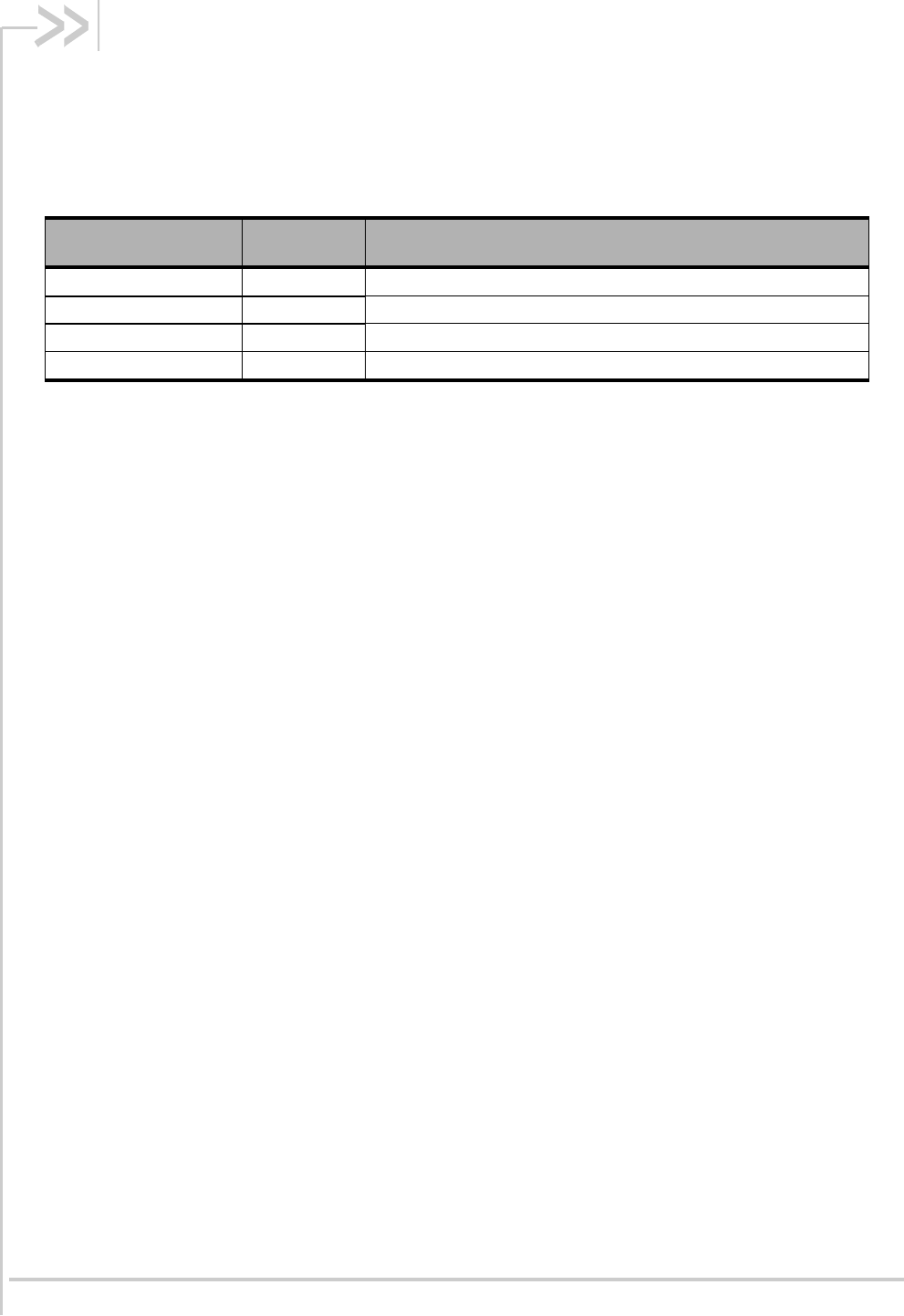
The MC7354B supports a PCM/I2S digital audio interface using a dedicated serial link for digital audio
data; all other signals, such as subcoding and control, are transmitted separately. The audio interface
can be switched from PCM to I2S and vice versa via AT commands.
Table 5. Audio Pin Description
Signal Name
Pin
Description
PCM_CLK/I2S_CLK
45
PCM Clock/I2S Clock
PCM_DOUT/I2S_DOUT
47
PCM Data Out/I2S Data Out
PCM_DIN/I2S_DIN
49
PCM Data In/I2S Data In
PCM_SYNC/I2S_WS
51
PCM SYNC/I2S WS

4117529 Rev 1.0 June 12, 2015 14
5. Regulatory Information
This module is designed to meet, and upon commercial release, will meet the requirements of the
following regulatory bodies and regulations, where applicable:
Federal Communications Commission (FCC) of the United States
The Certification and Engineering Bureau of Industry Canada (IC)
The National Communications Commission (NCC) of Taiwan, Republic of China
Upon commercial release, the following industry approvals will have been obtained, where applicable:
PTCRB
CDG2
Additional certifications and details on specific country approvals may be obtained upon customer
request; contact your Sierra Wireless account representative for details.
Additional testing and certification may be required for the end product with an embedded AirPrime
MC7354B modem and are the responsibility of the OEM. Sierra Wireless offers professional services-
based assistance to OEMs with the testing and certification process, if required.
5.1. Important Notice
Because of the nature of wireless communications, transmission and reception of data can never be
guaranteed. Data may be delayed, corrupted (i.e., have errors) or be totally lost. Although significant
delays or losses of data are rare when wireless devices such as the Sierra Wireless modem are used
in a normal manner with a well-constructed network, the Sierra Wireless modem should not be used
in situations where failure to transmit or receive data could result in damage of any kind to the user or
any other party, including but not limited to personal injury, death, or loss of property. Sierra Wireless
and its affiliates accept no responsibility for damages of any kind resulting from delays or errors in
data transmitted or received using the Sierra Wireless modem, or for failure of the Sierra Wireless
modem to transmit or receive such data.
5.2. Safety and Hazards
Do not operate your MC7354B modem:
In areas where blasting is in progress
Where explosive atmospheres may be present including refuelling points, fuel depots, and
chemical plants
Near medical equipment, life support equipment, or any equipment which may be susceptible
to any form of radio interference. In such areas, the MC7354B modem MUST BE POWERED
OFF. Otherwise, the MC7354B modem can transmit signals that could interfere with this
equipment.
In an aircraft, the MC7354B modem MUST BE POWERED OFF. Otherwise, the MC7354B modem
can transmit signals that could interfere with various onboard systems and may be dangerous to the
operation of the aircraft or disrupt the cellular network. Use of a cellular phone in an aircraft is illegal in
some jurisdictions. Failure to observe this instruction may lead to suspension or denial of cellular
telephone services to the offender, or legal action or both.
4117529 Rev 1.0 June 12, 2015 15
Hardware Integration Guide Regulatory Information
Some airlines may permit the use of cellular phones while the aircraft is on the ground and the door is
open. The MC7354B modem may be used normally at this time.
5.3. Important Compliance Information for North
American Users
The MC7354B modem has been granted modular approval for mobile applications. Integrators may
use the MC7354B in their final products without additional FCC/IC (Industry Canada) certification if
they meet the following conditions. Otherwise, additional FCC/IC approvals must be obtained.
1.
At least 20cm separation distance between the antenna and the user’s body must be
maintained at all times.
2.
To comply with FCC/IC regulations limiting both maximum RF output power and human
exposure to RF radiation, the maximum antenna gain including cable loss in a mobile-only
exposure condition must not exceed:
4.0 dBi in Cellular band
3.0 dBi in PCS band
3.0 dBi in LTE Band 2
4.0 dBi in LTE Band 4
4.0 dBi in LTE Band 5
4.0 dBi in LTE Band 13
4.0 dBi in LTE Band 17
3.0 dBi in LTE Band 25
3. The MC7354B may transmit simultaneously with other collocated radio transmitters within a
host device, provided the following conditions are met:
Each collocated radio transmitter has been certified by FCC / IC for mobile application.
At least 20 cm separation distance between the antennas of the collocated transmitters
and the user’s body must be maintained at all times.
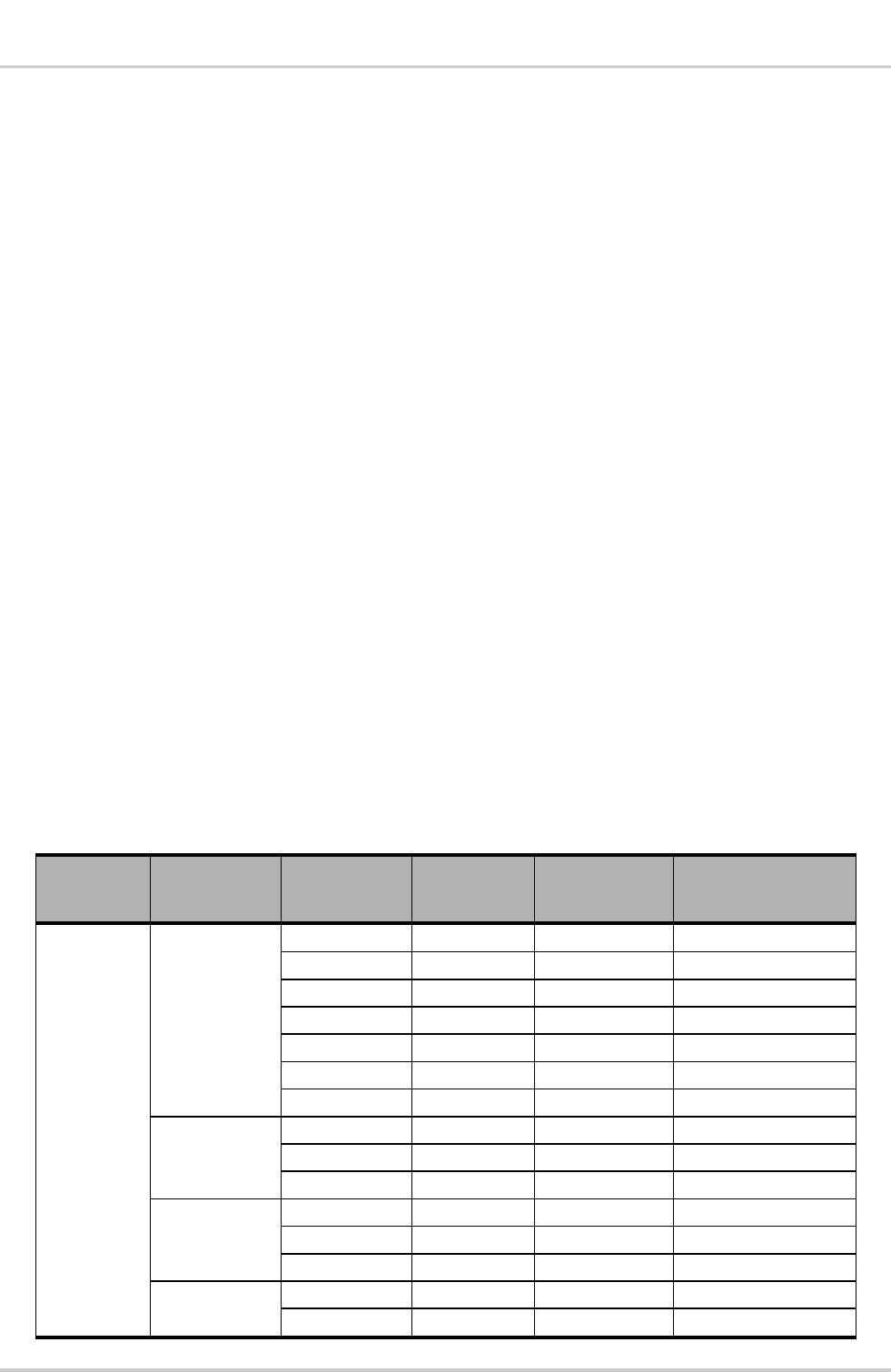
The output power and antenna gain must not exceed the limits and configurations
stipulated in the following table.
Device
Technology
Band
Frequency
(MHz)
Maximum
Antenna Gain
Maximum
Conducted Power
MC7354B
Module
LTE
2
1850 – 1910
3.0
+23 dBm ± 1 dB
4
1710 – 1755
4.0
+23 dBm ± 1 dB
5
824 – 849
4.0
+23 dBm ± 1 dB
13
777 – 787
4.0
+23 dBm ± 1 dB
17
704 – 716
4.0
+23 dBm ± 1 dB
25
1850 – 1915
3.0
+23 dBm ± 1 dB
26
814 – 849
4.0
+23 dBm ± 1 dB
UMTS
2
1850 – 1910
3.0
+23 dBm ± 1 dB
4
1710 – 1755
4.0
+23 dBm ± 1 dB
5
824 – 849
4.0
+23 dBm ± 1 dB
CDMA
BC0
824 – 849
4.0
+24 dBm +0.5/-1 dB
BC1
1850 – 1910
3.0
+24 dBm +0.5/-1 dB
BC10
817 – 824
4.0
+24 dBm +0.5/-1 dB
GSM
GSM 850
824 – 849
4.0
+32 dBm ± 1 dB
PCS 1900 1850 – 1910
3.0
+29 dBm ± 1 dB
4.0 dBi in LTE Band 26

4117529 Rev 1.0 June 12, 2015 16
Hardware Integration Guide
Regulatory Information
Device
Technology
Band
Frequency
(MHz)
Maximum
Antenna Gain
Maximum
Conducted Power
Collocated
transmitters*
WLAN
2400 – 2500
5.0
29
5150 – 580
5.0
29
WiMAX
2300 – 2400
5.0
29
2500 – 2700
5.0
29
3300 – 3800
5.0
29
BT
2400 – 2500
5.0
15
* Valid collocated Transmitter combinations: WLAN+BT; WiMAX+BT.(WLAN+WiMAX+BT is not permitted.)
4. A label must be affixed to the outside of the end product into which the AirPrime MC7354B
device is incorporated, with a statement similar to the following:
This device contains FCC ID: N7NMC7354B
Contains transmitter module IC: 2417C-MC7354B where 2417C-MC7354B is the module’s
certification number
5. A user manual with the end product must clearly indicate the operating requirements and
conditions that must be observed to ensure compliance with current FCC/IC RF exposure
guidelines.
The end product with an embedded AirPrime MC7354B device may also need to pass the FCC Part
15 unintentional emission testing requirements and be properly authorized.
Note: If this module is intended for use in a portable device, you are responsible for separate approval to
satisfy the SAR requirements of FCC Part 2.1093 and IC RSS-102.
4117529 Rev 1.0 June 12, 2015 17
6. References
6.1. Reference Documents
[1] AirPrime MC7354B Product Technical Specification and Customer Design Guidelines
Reference: TBD
[2] AirPrime MC Series Development Kit Quick Start Guide
Reference: 2130705
6.2. List of Abbreviations
Abbreviation
Definition
AC
Alternative Current
ADC
Analog to Digital Converter
A/D
Analog to Digital conversion
AF
Audio-Frequency
AT
Attention (prefix for modem commands)
AUX
Auxiliary
CAN
Controller Area Network
CB
Cell Broadcast
CEP
Circular Error Probable
CLK
Clock
CMOS
Complementary Metal Oxide Semiconductor
CS
Coding Scheme
CTS
Clear To Send
DAC
Digital to Analogue Converter
dB
Decibel
DC
Direct Current
DCD
Data Carrier Detect
DCE
Data Communication Equipment
DCS
Digital Cellular System
DR
Dynamic Range
DSR
Data Set Ready
DTE
Data Terminal Equipment
DTR
Data Terminal Ready
EDGE
Enhance Data rates for GSM Evolution
EFR
Enhanced Full Rate
E-GSM
Extended GSM
EGPRS
Enhance GPRS
EMC
Electromagnetic Compatibility
EMI
Electromagnetic Interference

4117529 Rev 1.0 June 12, 2015 18
Hardware Integration Guide
References
Abbreviation
Definition
EMS
Enhanced Message Service
EN
Enable
ESD
Electrostatic Discharges
FIFO
First In First Out
FR
Full Rate
FTA
Full Type Approval
GND
Ground
GPI
General Purpose Input
GPC
General Purpose Connector
GPIO
General Purpose Input Output
GPO
General Purpose Output
GPRS
General Packet Radio Service
GPS
Global Positioning System
GSM
Global System for Mobile communications
HR
Half Rate
I/O
Input / Output
LED
Light Emitting Diode
LGA
Land Grid Array
LNA
Low Noise Amplifier
MAX
Maximum
MIC
Microphone
MIN
Minimum
MMS
MultiMedia Message Service
MO
Mobile Originated
MT
Mobile Terminated
na
Not Applicable
NC
Not Connected
NF
Noise Factor
NMEA
National Marine Electronics Association
NOM
Nominal
NTC
Negative Temperature Coefficient
PA
Power Amplifier
Pa
Pascal (for speaker sound pressure measurements)
PBCCH
Packet Broadcast Control Channel
PC
Personal Computer
PCB
Printed Circuit Board
PDA
Personal Digital Assistant
PFM
Power Frequency Modulation
PSM
Phase Shift Modulation
PWM
Pulse Width Modulation
RAM
Random Access Memory
RF
Radio Frequency
RFI
Radio Frequency Interference
RHCP
Right Hand Circular Polarization

4117529 Rev 1.0 June 12, 2015 19
Hardware Integration Guide
References
Abbreviation
Definition
RI
Ring Indicator
RST
Reset
RTC
Real Time Clock
RTCM
Radio Technical Commission for Maritime services
RTS
Request To Send
RX
Receive
SCL
Serial Clock
SDA
Serial Data
SIM
Subscriber Identification Module
SMS
Short Message Service
SPI
Serial Peripheral Interface
SPL
Sound Pressure Level
SPK
Speaker
SRAM
Static RAM
TBC
To Be Confirmed
TDMA
Time Division Multiple Access
TP
Test Point
TVS
Transient Voltage Suppressor
TX
Transmit
TYP
Typical
UART
Universal Asynchronous Receiver-Transmitter
USB
Universal Serial Bus
USSD
Unstructured Supplementary Services Data
VSWR
Voltage Standing Wave Ratio