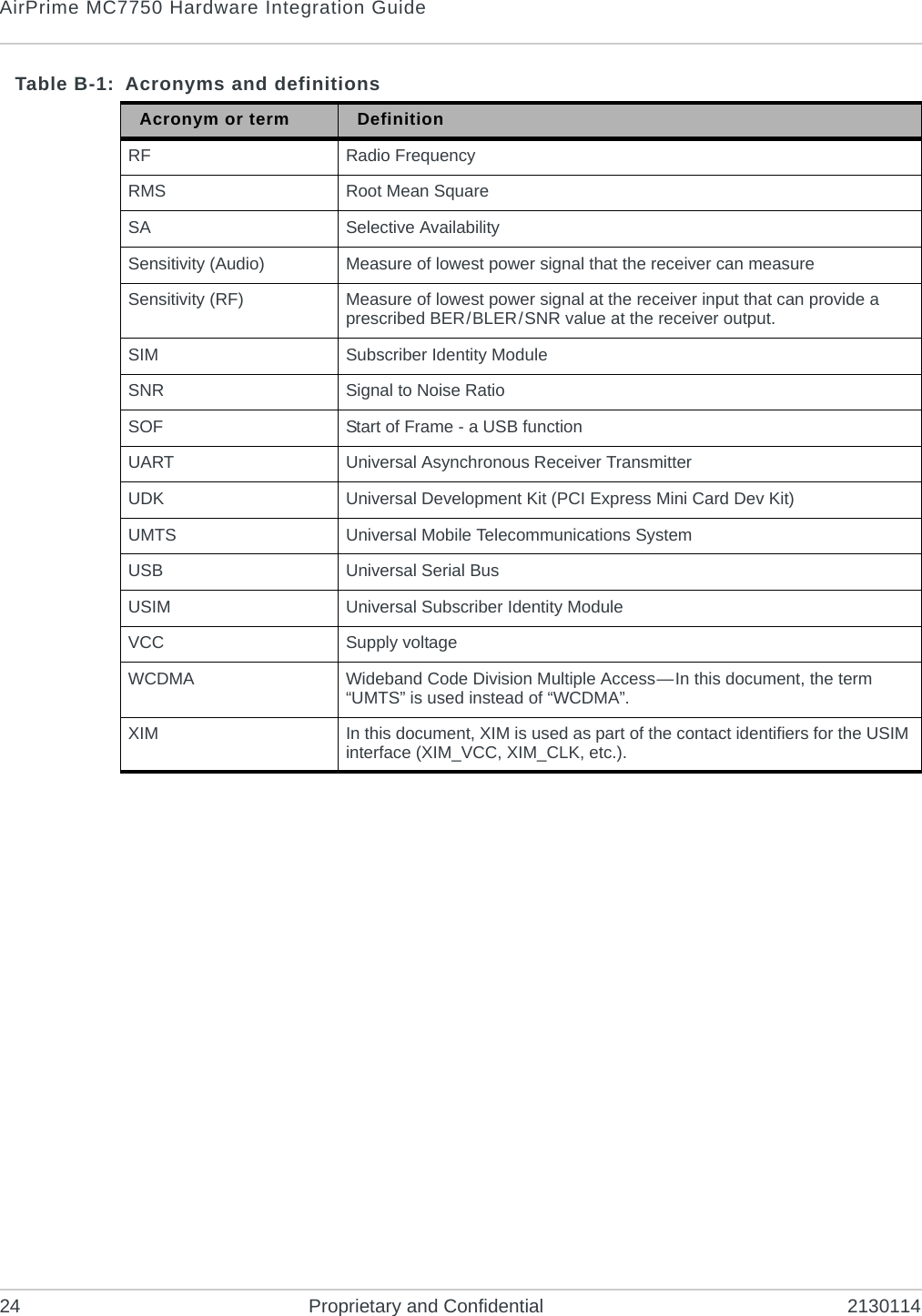
Sierra Wireless MC7750-L Cellular/PCS GSM/Edge/WCDMA/CDMA/EVDO and 700MHz User Manual AirPrime MC7750 Hardware Integration Guide

Sierra Wireless Inc. Cellular/PCS GSM/Edge/WCDMA/CDMA/EVDO and 700MHz AirPrime MC7750 Hardware Integration Guide

Users Manual

AirPrime MC7750Hardware Integration Guide2130114Rev 3.0.3
PrefaceRev 3.0.3  Mar.12 Proprietary and Confidential 3Important NoticeDue to the nature of wireless communications, transmission and reception of data can never be guaranteed. Data may be delayed, corrupted (i.e., have errors) or be totally lost. Although significant delays or losses of data are rare when wireless devices such as the Sierra Wireless modem are used in a normal manner with a well-constructed network, the Sierra Wireless modem should not be used in situations where failure to transmit or receive data could result in damage of any kind to the user or any other party, including but not limited to personal injury, death, or loss of property. Sierra Wireless accepts no responsibility for damages of any kind resulting from delays or errors in data transmitted or received using the Sierra Wireless modem, or for failure of the Sierra Wireless modem to transmit or receive such data.Safety and HazardsDo not operate the Sierra Wireless modem in areas where blasting is in progress, where explosive atmospheres may be present, near medical equipment, near life support equipment, or any equipment which may be susceptible to any form of radio interference. In such areas, the Sierra Wireless modem MUST BE POWERED OFF. The Sierra Wireless modem can transmit signals that could interfere with this equipment.Do not operate the Sierra Wireless modem in any aircraft, whether the aircraft is on the ground or in flight. In aircraft, the Sierra Wireless modem MUST BE POWERED OFF. When operating, the Sierra Wireless modem can transmit signals that could interfere with various onboard systems.Note: Some airlines may permit the use of cellular phones while the aircraft is on the ground and the door is open. Sierra Wireless modems may be used at this time.The driver or operator of any vehicle should not operate the Sierra Wireless modem while in control of a vehicle. Doing so will detract from the driver or operator's control and operation of that vehicle. In some states and provinces, operating such communications devices while in control of a vehicle is an offence.Limitation of LiabilityThe information in this manual is subject to change without notice and does not represent a commitment on the part of Sierra Wireless. SIERRA WIRELESS AND ITS AFFILIATES SPECIFICALLY DISCLAIM LIABILITY FOR ANY AND ALL DIRECT, INDIRECT, SPECIAL, GENERAL, INCIDENTAL, CONSEQUENTIAL, PUNITIVE OR EXEMPLARY DAMAGES INCLUDING, BUT NOT LIMITED TO, LOSS OF PROFITS OR REVENUE OR ANTICIPATED PROFITS OR REVENUE ARISING OUT OF THE USE OR INABILITY TO USE ANY SIERRA WIRELESS PRODUCT, EVEN IF SIERRA WIRELESS AND/OR ITS AFFILIATES HAS BEEN ADVISED OF THE POSSIBILITY OF SUCH DAMAGES OR THEY ARE FORESEEABLE OR FOR CLAIMS BY ANY THIRD PARTY.Notwithstanding the foregoing, in no event shall Sierra Wireless and/or its affiliates aggregate liability arising under or in connection with the Sierra Wireless product, regardless of the number of events, occurrences, or claims giving rise to liability, be in excess of the price paid by the purchaser for the Sierra Wireless product.
AirPrime MC7750 Hardware Integration Guide4 Proprietary and Confidential 2130114Patents This product may contain technology developed by or for Sierra Wireless Inc.This product includes technology licensed from QUALCOMM®.This product is manufactured or sold by Sierra Wireless Inc. or its affiliates under one or more patents licensed from InterDigital Group.Copyright © 2012 Sierra Wireless. All rights reserved.Trademarks Sierra Wireless™, AirPrime™, Watcher™ and the Sierra Wireless logo are trademarks of Sierra Wireless.Windows® is a registered trademark of Microsoft Corporation.Other trademarks are the property of their respective owners.Contact InformationConsult our website for up-to-date product descriptions, documentation, application notes, firmware upgrades, troubleshooting tips, and press releases:www.sierrawireless.comRevision HistorySales Desk: Phone: 1-604-232-1488Hours: 8:00 AM to 5:00 PM Pacific TimeE-mail: sales@sierrawireless.comPost: Sierra Wireless13811 Wireless WayRichmond, BCCanada            V6V 3A4Fax: 1-604-231-1109Web: www.sierrawireless.comRevision number Release date Changes3.0.1 January 2011 •MC7750 FCC submission3.0.2 March 2011 •Revised regulatory details3.0.3 March 2011 •Revised regulatory details (Simultaneous Transmission Evaluation)
Rev 3.0.3  Mar.12 Proprietary and Confidential 5ContentsIntroduction . . . . . . . . . . . . . . . . . . . . . . . . . . . . . . . . . . . . . . . . . . . . . . . . . . . . .7The Universal Development Kit . . . . . . . . . . . . . . . . . . . . . . . . . . . . . . . . . . .  7Required connectors  . . . . . . . . . . . . . . . . . . . . . . . . . . . . . . . . . . . . . . . . . . .  7Power Interface . . . . . . . . . . . . . . . . . . . . . . . . . . . . . . . . . . . . . . . . . . . . . . . . . .9Overview of operation  . . . . . . . . . . . . . . . . . . . . . . . . . . . . . . . . . . . . . . . . . .  9Power signals . . . . . . . . . . . . . . . . . . . . . . . . . . . . . . . . . . . . . . . . . . . . . . .9Power supply  . . . . . . . . . . . . . . . . . . . . . . . . . . . . . . . . . . . . . . . . . . . . . . .9Electrostatic discharge (ESD)  . . . . . . . . . . . . . . . . . . . . . . . . . . . . . . . . . .9Module power states  . . . . . . . . . . . . . . . . . . . . . . . . . . . . . . . . . . . . . . . . . .  10Disconnected state   . . . . . . . . . . . . . . . . . . . . . . . . . . . . . . . . . . . . . . . . .10Off state  . . . . . . . . . . . . . . . . . . . . . . . . . . . . . . . . . . . . . . . . . . . . . . . . . .10Sleep state . . . . . . . . . . . . . . . . . . . . . . . . . . . . . . . . . . . . . . . . . . . . . . . .11Normal state . . . . . . . . . . . . . . . . . . . . . . . . . . . . . . . . . . . . . . . . . . . . . . .11Low power state . . . . . . . . . . . . . . . . . . . . . . . . . . . . . . . . . . . . . . . . . . . .11RF Integration  . . . . . . . . . . . . . . . . . . . . . . . . . . . . . . . . . . . . . . . . . . . . . . . . . .13RF connection  . . . . . . . . . . . . . . . . . . . . . . . . . . . . . . . . . . . . . . . . . . . . . . .  14Ground connection. . . . . . . . . . . . . . . . . . . . . . . . . . . . . . . . . . . . . . . . . . . .  14Shielding   . . . . . . . . . . . . . . . . . . . . . . . . . . . . . . . . . . . . . . . . . . . . . . . . .14Antenna and cabling   . . . . . . . . . . . . . . . . . . . . . . . . . . . . . . . . . . . . . . . .14Interference and sensitivity. . . . . . . . . . . . . . . . . . . . . . . . . . . . . . . . . . . . . .  15Power supply noise  . . . . . . . . . . . . . . . . . . . . . . . . . . . . . . . . . . . . . . . . .15Interference from other wireless devices  . . . . . . . . . . . . . . . . . . . . . . . . .15Device-generated RF . . . . . . . . . . . . . . . . . . . . . . . . . . . . . . . . . . . . . . . .16Regulatory Information . . . . . . . . . . . . . . . . . . . . . . . . . . . . . . . . . . . . . . . . . .  17Important notice . . . . . . . . . . . . . . . . . . . . . . . . . . . . . . . . . . . . . . . . . . . . . .  17Safety and hazards  . . . . . . . . . . . . . . . . . . . . . . . . . . . . . . . . . . . . . . . . . . .  17Important compliance information for North American users . . . . . . . . . . . .  18
AirPrime MC7750 Hardware Integration Guide6 Proprietary and Confidential 2130114OEM integration. . . . . . . . . . . . . . . . . . . . . . . . . . . . . . . . . . . . . . . . . . . . . .   18Application of regulatory guidelines . . . . . . . . . . . . . . . . . . . . . . . . . . . . . 18OEM device classification process  . . . . . . . . . . . . . . . . . . . . . . . . . . . . . 19Acronyms and Definitions . . . . . . . . . . . . . . . . . . . . . . . . . . . . . . . . . . . . . . .   23Index. . . . . . . . . . . . . . . . . . . . . . . . . . . . . . . . . . . . . . . . . . . . . . . . . . . . . . . . .   25
Rev 3.0.3  Mar.12 Proprietary and Confidential 711: IntroductionSierra Wireless’ AirPrime Intelligent Embedded Modules form the radio component for the products in which they are embedded.The AirPrime MC7750 is available for use on LTE, CDMA, and GSM networks.Note: An understanding of network technology, and experience in integrating hardware components into electronic equipment is assumed.Purpose of this guideThis guide addresses issues that affect the integration of AirPrime embedded modules into host products, and includes design recommendations for the host products.The Universal Development KitSierra Wireless manufactures a Universal Development Kit (UDK) that facilitates all phases of the integration process.This kit is a hardware development platform that is designed to support AirPrime Mini Card embedded modules. It contains the hardware components that are typically necessary for evaluating and developing with the module, including:•Development board•Cables•Antennas•Other accessoriesFor instructions on setting up the UDK, see PCI Express Mini Card Dev Kit Quick Start Guide (Document 2130705).Required connectorsNote: Contact vendors before choosing your connectors—the numbers included here are for reference only. Choose connectors that are appro-priate to your design.When integrating AirPrime embedded modules into your host device, you need the following connector types:•RF cables that mate with Hirose U.FL connectors (model U.FL #CL331-0471-0-10). Modules include one to three connector jacks depending on individual module support for diversity or GPS functionality.•Industry-standard mating connector for 52-pin EDGE—some manufacturers include Tyco, Foxconn, and Molex. For example, the connector used on the Mini Card Dev Kit board is a Molex 67910-0001.
AirPrime MC7750 Hardware Integration Guide8 Proprietary and Confidential 2130114•Industry-standard USIM connector—the actual connector you use depends on how your device exposes the USIM socket. For example, the USIM connector used on the Mini Card Dev Kit board is an ITT CCM03-3518.
Rev 3.0.3  Mar.12 Proprietary and Confidential 922: Power InterfaceOverview of operationAirPrime embedded modules are designed to use a 3.3V (nominal) power supply provided by the host. It is the host’s responsibility to provide safe and continuous power to the module at all times; the module does NOT have an independent power supply, or protection circuits to guard against electrical issues.The module’s power state is controlled by the host’s assertion/deassertion of W_Disable#. The module also monitors its supply voltage and requests shutdown if the supply is insufficient.Power signalsThe module must be connected to a 3.3V power supply, as described in PCI Express Mini Card Electromechanical Specification Revision 1.1.For detailed pinout and voltage/current requirements, see the Product Specification Document for your AirPrime embedded module.Power supplyElectrostatic discharge (ESD)You are responsible for ensuring that the host has adequate ESD protection on digital circuits and antenna ports as described by the following specifications:•(Operational) RF port (antenna launch and RF connector): IEC-61000-4-2—Level (Electrostatic Discharge Immunity Test)•(Non-operational) Host connector interface: JESD22-A114-B +/-1kV Human Body Model and JESD22-C101 +/- 125 V Charged Device ModelThis guide provides specific recommendations where needed, however, the level of protection required depends on your application.Table 2-1: Power supply requirementsRequirement type ValuePower supply 3.3 V (nominal)Voltage range 3.0–3.6 VMaximum peak current (worst-case) 2.75 A
AirPrime MC7750 Hardware Integration Guide10 Proprietary and Confidential 2130114Note: ESD protection is highly recommended for the USIM connector at the point where the contacts are exposed, and for any other signals from the host interface that would be subjected to ESD by the user of the product.Module power statesNote: The module unit defaults to the Normal state when VCC is first applied in the absence of W_Disable# control.The module has five power states:•DisconnectedNo power to the module.•OffPower to the module, but the module is powered off.•SleepState between calls or data connections. Module cycles between wake and sleep.•NormalThe module is active. Several modes are possible (Receive, Transmit, Sleep, Shutdown).•Low power (“airplane mode”)The module is active, but RF is disabled.State machines are implemented in the module to monitor the power supply and operating temperature.Disconnected stateNote: The difference between the Discon-nected and Off states is that, in the Off state, the module is still connected to the power source and draws minimal current.This state occurs when there is no power to the module—the host power source is disconnected from the module and all voltages associated with the module are at 0 V.Whether the host device is also powered off depends on the power rail design:•If the connection between the power rail and the module is controlled by the host, the host can stay powered on and cut the power to put the module into the disconnected state.•If the power rail is shared between the host device and the module, the module is powered off when the host is powered off.Off stateIn this state, the host is powered up and the module is powered down (but still connected to the power source).The host keeps the module powered off by driving the W_Disable# signal low. In this state, the module draws minimal current.
Power InterfaceRev 3.0.3  Mar.12 Proprietary and Confidential 11Sleep stateIn this state, the host and module are powered up, and the module cycles between wake (polling the network) and sleep, at network provider-determined interval. This is the normal state of the module between calls or data connections.Note: This is the default state when VCC is first applied in the absence of W_Disable# control.Normal stateThis is the active state of the module. In this state:•The module is fully powered.•The module is capable of placing/receiving calls or establishing data connec-tions on the wireless network.•The USB interface is fully active.Low power stateIn this state (also called “airplane mode”), RF (both Rx and Tx) is disabled in the module, but the USB interface is still active.
AirPrime MC7750 Hardware Integration Guide12 Proprietary and Confidential 2130114
Rev 3.0.3  Mar.12 Proprietary and Confidential 1333: RF IntegrationThe AirPrime MC7750 operates on the following frequencies:Table 3-1: Supported RF bands (MC7750)  Technology Band Frequency range (MHz)LTE 13 Tx: 777–787Rx: 746–756WCDMAaa. WCDMA channel spacing is 5 MHz, but this can be adjusted to optimize performance in a particular deployment scenario.1 (UMTS 2100) Tx: 1920–1980Rx: 2110–21702 (UMTS 1900) Tx: 1850–1910Rx: 1930–19905 (UMTS 850) Tx: 824–849Rx: 869–8948 (UMTS 900) Tx: 880–915Rx: 925–960GSM GSM 850 Tx: 824–849Rx: 869–894EGSM 900 Tx: 880–915Rx: 925–960DCS 1800 Tx: 1710–1785Rx: 1805–1880PCS 1900 Tx: 1850–1910Rx: 1930–1990CDMA PCS Tx: 1850–1910Rx: 1930–1990Cellular Tx: 824–849Rx: 869–894GPS GPS 1575.42
AirPrime MC7750 Hardware Integration Guide14 Proprietary and Confidential 2130114RF connectionWhen attaching an antenna to the module:Note: To disconnect the antenna, make sure you use the Hirose U.FL connector removal tool(P/N UFL-LP-N-2(01)) to prevent damage to the module or coaxial cable assembly.•Use a Hirose U.FL connector (model U.FL #CL331-0471-0-10) to attach an antenna to a connection point on the module.•Match coaxial connections between the module and the antenna to 50 •Minimize RF cable losses to the antenna; the recommended maximum cable loss for antenna cabling is 0.5 dB.Ground connectionWhen connecting the module to system ground:•Prevent noise leakage by establishing a very good ground connection to the module through the host connector.•Connect to system ground using the two mounting holes at the top of the module.•Minimize ground noise leakage into the RF.Depending on the host board design, noise could potentially be coupled to the module from the host board. This is mainly an issue for host designs that have signals traveling along the length of the module, or circuitry operating at both ends of the module interconnects.ShieldingThe module is fully shielded to protect against EMI and to ensure compliance with FCC Part 15 - “Radio Frequency Devices” (or equivalent regulations in other jurisdictions).Note: The module shields must NOT be removed.Note: Values in this guide are taken from the appro-priate product specifi-cation documents (PSDs) —in the case of a discrepancy between this document and the relevant PSD, use the value listed in the PSD.Antenna and cablingWhen selecting the antenna and cable, it is critical to RF performance to match antenna gain and cable loss.Choosing the correct antenna and cablingConsider the following points for proper matching of antennas and cabling:•The antenna (and associated circuitry) should have a nominal impedance of 50  with a return loss of better than 10 dB across each frequency band of operation.•The system gain value affects both radiated power and regulatory (FCC, IC, CE, etc.) test results.
RF IntegrationRev 3.0.3  Mar.12 Proprietary and Confidential 15Developing custom antennasConsider the following points when developing custom-designed antennas:•A skilled RF engineer should do the development to ensure that the RF performance is maintained.•Identify the bands that need to be supported.Determining the antenna’s locationConsider the following points when deciding where to put the antenna:•Antenna location may affect RF performance. Although the module is shielded to prevent interference in most applications, the placement of the antenna is still very important—if the host device is insufficiently shielded, high levels of broadband or spurious noise can degrade the module’s perfor-mance.•Connecting cables between the module and the antenna must have 50  impedance. If the impedance of the module is mismatched, RF performance is reduced significantly.•Antenna cables should be routed, if possible, away from noise sources (switching power supplies, LCD assemblies, etc.). If the cables are near the noise sources, the noise may be coupled into the RF cable and into the antenna.Note: The MC7750 is based on ZIF (Zero Inter-mediate Frequency) technologies. When performing EMC (Electro-magnetic Compatibility) tests, there are no IF (Intermediate Frequency) components from the module to consider.Interference and sensitivitySeveral sources of interference can affect the RF performance of the module (RF desense). Common sources include power supply noise and device-generated RF.RF desense can be addressed through a combination of mitigation techniques and radiated sensitivity measurement.Power supply noiseNoise in the power supply can lead to noise in the RF signal. Note: Values in this guide are taken from the MC7750 product technical specification (PTS) —in the case of a discrepancy between this document and the PTS, use the value listed in the PTS.The power supply ripple limit for the module is no more than 200 mVp-p 1 Hz to 100 kHz. This limit includes voltage ripple due to transmitter burst activity.Interference from other wireless devicesWireless devices operating inside the host device can cause interference that affects the module.To determine the most suitable locations for antennas on your host device, evaluate each wireless device’s radio system, considering the following:•Any harmonics, sub-harmonics, or cross-products of signals generated by wireless devices that fall in the module’s Rx range may cause spurious response, resulting in decreased Rx performance.
AirPrime MC7750 Hardware Integration Guide16 Proprietary and Confidential 2130114•The Tx power and corresponding broadband noise of other wireless devices may overload or increase the noise floor of the module’s receiver, resulting in Rx desense.The severity of this interference depends on the closeness of the other antennas to the module’s antenna. To determine suitable locations for each wireless device’s antenna, thoroughly evaluate your host device’s design.Device-generated RFNote: The module can cause interference with other devices such as hearing aids and on-board speakers.Wireless devices such as AirPrime embedded modules transmit in bursts (pulse transients) for set durations (RF burst frequencies). Hearing aids and speakers convert these burst frequencies into audible frequencies, resulting in audible noise. All electronic computing devices generate RF interference that can negatively affect the receive sensitivity of the module.The proximity of host electronics to the antenna in wireless devices can contribute to decreased Rx performance. Components that are most likely to cause this include:•Microprocessor and memory•Display panel and display drivers•Switching-mode power supplies
Rev 3.0.3  Mar.12 Proprietary and Confidential 17AA: Regulatory InformationImportant noticeBecause of the nature of wireless communications, transmission and reception of data can never be guaranteed. Data may be delayed, corrupted (i.e., have errors) or be totally lost. Although significant delays or losses of data are rare when wireless devices such as the Sierra Wireless modem are used in a normal manner with a well-constructed network, the Sierra Wireless modem should not be used in situations where failure to transmit or receive data could result in damage of any kind to the user or any other party, including but not limited to personal injury, death, or loss of property. Sierra Wireless and its affiliates accept no responsibility for damages of any kind resulting from delays or errors in data transmitted or received using the Sierra Wireless modem, or for failure of the Sierra Wireless modem to transmit or receive such data.Safety and hazardsDo not operate your MC7750 modem:•In areas where blasting is in progress•Where explosive atmospheres may be present including refuelling points, fuel depots, and chemical plants•Near medical equipment, life support equipment, or any equipment which may be susceptible to any form of radio inter-ference. In such areas, the MC7750 modem MUST BE POWERED OFF. Otherwise, the MC7750 modem can transmit signals that could interfere with this equipment.In an aircraft, the MC7750 modem MUST BE POWERED OFF. Otherwise, the MC7750 modem can transmit signals that could interfere with various onboard systems and may be dangerous to the operation of the aircraft or disrupt the cellular network. Use of a cellular phone in an aircraft is illegal in some jurisdictions. Failure to observe this instruction may lead to suspension or denial of cellular telephone services to the offender, or legal action or both.Some airlines may permit the use of cellular phones while the aircraft is on the ground and the door is open. The MC7750 modem may be used normally at this time.
AirPrime MC7750 Hardware Integration Guide18 Proprietary and Confidential 2130114Important compliance information for North American usersThe MC7750 modem has been granted modular approval for mobile applications. Integrators may use the MC7750 modem in their final products without additional FCC/IC (Industry Canada) certification if the following conditions are met. Otherwise, additional FCC/IC approvals must be obtained.•Although the MC7750 modem has been granted module approval, there are many conditions attached to this approval; final host integration will likely require additional testing. Detailed guidelines are described in OEM device classification process on page 19 to assist OEM module integrators in deter-mining the extent of additional testing necessary to comply with FCC require-ments.•The end product with an embedded MC7750 modem must be evaluated for simultaneous transmission requirements. See Simultaneous transmission evaluation on page 20 for details.•A user manual with the end product must clearly indicate the operating requirements and conditions that must be observed to ensure compliance with current FCC / IC RF exposure guidelines. See OEM product instruction manual content on page 21 for details.•To comply with FCC / IC regulations limiting both maximum RF output power and human exposure to RF radiation, the maximum antenna gain including cable loss in a mobile-only exposure condition must not exceed:·Part 22 (Cellular): 7.0 dBi·Part 24 (PCS): 3.0 dBi·Part 27 (Band 13): 9.0 dBi•A label must be affixed to the outside of the end product into which the MC7750 modem is incorporated, with a statement similar to the following:· This device contains FCC ID: N7NMC7750.Contains transmitter module IC: 2417C-MC7750 where 2417C-MC7750 is the module’s certification number.The end product with an embedded MC7750 modem may also need to pass the FCC Part 15 unintentional emission testing requirements and be properly authorized per FCC Part 15.Note: If this module is intended for use in a portable device, you are responsible for separate approval to satisfy the SAR requirements of FCC Part 2.1093 and IC RSS-102.OEM integrationApplication of regulatory guidelinesBecause ‘near-body’ devices (handhelds, laptops, tablets, scanners, etc.) vary widely in design features, physical configurations, and use-models, module integrators shall follow the guidelines below regarding device classification and simultaneous transmission, and seek guidance from their preferred regulatory
Rev 3.0.3  Mar.12 Proprietary and Confidential 19test lab to determine how regulatory guidelines will impact the device compliance. Proactive management of the regulatory process will minimize unexpected schedule delays and costs due to unplanned testing activities.Device classificationsThe OEM integrator must determine the minimum distance required between their device and the user’s body.The FCC provides device classification definitions to assist in making the correct determination. Note that these classifications are guidelines only; strict adherence to a device classification may not satisfy the regulatory requirement as near-body device design details may vary widely.FCC definitions:Portable: (§2.1093)—A portable device is defined as a transmitting device designed to be used so that the radiating structure(s) of the device is/are within 20 centimeters of the body of the user.Mobile: (§2.1091)(b)—A mobile device is defined as a transmitting device designed to be used in other than fixed locations and to generally be used in such a way that a separation distance of at least 20 centimeters is normally maintained between the transmitter’s radiating structure(s) and the body of the user or nearby persons.Per §2.1091d(d)(4) In some cases (for example, modular or desktop transmitters), the potential conditions of use of a device may not allow easy classification of that device as either Mobile or Portable. In these cases, applicants are responsible for determining minimum distances for compliance for the intended use and installation of the device based on evaluation of either specific absorption rate (SAR), field strength, or power density, whichever is most appropriate.OEM device classification processThe primary factor in determining whether a device will be classified as a Portable product or as a Mobile product is antenna separation distance (body to radiating antenna element).The review process between the OEM module integrator and the preferred regulatory test lab is a crucial step in determining the appropriate device classification, as it is impractical for Sierra Wireless to define all possible combinations of design features, antennas, physical configurations, and use-models.1. Perform a device review with the preferred regulatory test lab to confirm device classification.2. Determine the Certification type (Standalone or C2PC from an existing Modular Grant).3. If the device classification is:·Portable: Preferred regulatory test lab to determine if a PBA or KDB is required.·Mobile: Preferred regulatory test lab to determine if a PBA is required.(Note: A PBA or KDB will likely be required for new technologies such as LTE or WiMAX.)
AirPrime MC7750 Hardware Integration Guide20 Proprietary and Confidential 21301144. If the device classification is Mobile, confirm the antenna does not violate the Gain Limits specific to the module grant as specified in Important compliance information for North American users on page 18.5. Outline and execute a test plan with the preferred regulatory test lab.Testing is likely to include some or all of Parts 15, 22, 24, 27, and either SAR (for Portable devices) or MPE (for Mobile devices).6. Follow product labeling requirements as described in Important compliance information for North American users on page 18. (Ref §2.925) 7. Include the OEM product instruction manual content on page 21 boilerplate text within the host product’s instruction manual.Simultaneous transmission evaluationThe MC7750 modem has been evaluated for collocated transmission and may transmit simultaneously with other collocated radio transmitters within a host device provided the following conditions are met:•All antennas (MC7750 transmit antenna and other collocated transmit antennas) provide > 20 cm separation distance to the end user (FCC mobile categorization), and•The collocated transmitter maximum average transmit power and maximum antenna gain do not exceed the levels listed in Tabl e A - 1  per the MC7750 platform module-level maximum permissible exposure (MPE) report, or the power defined in a subsequently issued host-specific MPE report.Table A-1: Summary of Maximum Conducted Power and Antenna GainDevice Technology Frequency (MHz) Conducted Power Limit (dBm) Antenna Gain Limit (dBi)MC7750 GPRS/EDGE 824–849 33 5.0UMTS 824–849 24 5.0CDMA 824–849 25 5.0GPRS/EDGE 1850–1910 30 3.0UMTS 1850–1910 24 3.0CDMA 1850–1910 25 3.0LTE 777–787 24 7.0Collocated radio transmitters WLAN 2400–2500 29 4.0WLAN 5150–5850 29 4.0WiMAX 2300–2400 27 5.0WiMAX 2500–2700 27 5.0WiMAX 3300–3800 27 5.0BT 2400–2500 15 5.0
Rev 3.0.3  Mar.12 Proprietary and Confidential 21OEM product instruction manual contentConsistent with §2.909(a), the following text must be included within the user’s manual or operator instruction guide for the final commercial product. (OEM-specific content is displayed in italics.)Operating Requirements and ConditionsThe design of (Product Name) complies with U.S. Federal Communications Commission (FCC) guidelines respecting safety levels of radio frequency (RF) exposure for (OEM to insert device classification: Mobile or Portable) devices.FCC ID: (Include Standalone FCC ID or Module FCC ID as required) Note: Include the following RF Exposure statement for Mobile devices only.RF Exposure - This device is only authorized for use in a mobile application. At least 20 cm (8 inches) of separation distance between the (Product Name) device and the user's body must be maintained at all times.Note: Include the following RF Exposure statement for Portable devices only.RF Exposure - This device has been tested for compliance with FCC RF exposure limits in a portable configuration. At least (Insert Required Separation Distance from RF Exposure Evaluation) cm of separation distance between the (Product Name) device and the user's body must be maintained at all times. This device must not be used with any other antenna or transmitter that has not been approved to operate in conjunction with this device.Note: Always include the following Caution statement.CAUTION: Any changes or modifications not expressly approved by (Company Name) or Sierra Wireless could void the user’s authority to operate the equipment.Note: Include the following statement if Part 15 of the FCC Rules is required. Integration into host devices containing unlicensed devices may require additional comments in this section. The OEM should confirm the extent of their user’s guide content with their preferred regulatory test lab.Note: This equipment has been tested and found to comply with the limits for a (OEM to insert device type: Class A or Class B) digital device, pursuant to Part 15 of the FCC Rules. (OEM must follow Part 15 guidelines (§15.105 and §15.19) to determine additional statements required in this section for their device class)
AirPrime MC7750 Hardware Integration Guide22 Proprietary and Confidential 2130114
Rev 3.0.3  Mar.12 Proprietary and Confidential 23BB: Acronyms and Definitions.Table B-1: Acronyms and definitionsAcronym or term DefinitionAGC Automatic Gain ControlBER Bit Error Rate - a measure of receive sensitivityBLER Block Error RateCall Box Base Station Simulator - Agilent E8285A or 8960, Rohde & Schwarz CMU200CDMA Code Division Multiple AccessdB Decibel = 10 x log10 (P1/P2)P1 is calculated power; P2 is reference powerDecibel = 20 x log10 (V1/V2)V1 is calculated voltage, V2 is reference voltagedBm Decibels, relative to 1 mW - Decibel(mW) = 10 x log10 (Pwr (mW)/1mW)DUT Device Under TestEDGE Enhanced Data rates for GSM EvolutionEM Embedded ModuleESD ElectroStatic DischargeFER Frame Error Rate - a measure of receive sensitivityGPRS General Packet Radio ServicesGPS Global Positioning SystemGSM Global System for Mobile communicationsHz Hertz = 1 cycle/secondinrush current Peak current drawn when a device is connected or powered onIS-2000 3G radio standards for voice and data (CDMA only)IS-95 2G radio standards targeted for voice (cdmaONE)LDO Low Drop Out - refers to linear regulatorMHz MegaHertz = 10E6 Hertz (Hertz = 1 cycle/second)MIO Module Input/OutputMPE Maximum Permissible Exposure—the level of radiation to which a person may be exposed without hazardous effect or adverse biological changesOTA Over-The-Air or Radiated through the antennaPCS Personal Communication System - PCS spans the 1.9 GHz radio spectrum
AirPrime MC7750 Hardware Integration Guide24 Proprietary and Confidential 2130114RF Radio FrequencyRMS Root Mean SquareSA Selective AvailabilitySensitivity (Audio) Measure of lowest power signal that the receiver can measureSensitivity (RF) Measure of lowest power signal at the receiver input that can provide a prescribed BER/BLER/SNR value at the receiver output.SIM Subscriber Identity ModuleSNR Signal to Noise RatioSOF Start of Frame - a USB functionUART Universal Asynchronous Receiver TransmitterUDK Universal Development Kit (PCI Express Mini Card Dev Kit)UMTS Universal Mobile Telecommunications SystemUSB Universal Serial BusUSIM Universal Subscriber Identity ModuleVCC Supply voltageWCDMA Wideband Code Division Multiple Access—In this document, the term “UMTS” is used instead of “WCDMA”.XIM In this document, XIM is used as part of the contact identifiers for the USIM interface (XIM_VCC, XIM_CLK, etc.).Table B-1: Acronyms and definitionsAcronym or term Definition
Rev 3.0.3  Mar.12 Proprietary and Confidential 25Aacronyms and definitions,  23– 24antennaconnection considerations,  14custom, considerations,  15limit, matching coaxial connections,  14location, considerations,  15matching, considerations,  14maximum cable loss,  14Ccable lossantenna, maximum,  14connectiongrounding,  14connectors, requiredEDGE mating (52-pin),  7host-module,  7– 8RF, Hirose,  7USIM,  8Ddesense. See RFdisconnected, module power state,  10EEDGE connector, manufacturers,  7electrostatic discharge. See ESDESDprotection requirements,  9– 10Ggroundingconnection considerations,  14Iimpedancemodule-antenna,  15interferencedevice generated,  16power supply noise,  15wireless devices,  15Llow power, module power state,  11Mmodulepower states,  10– 11Nnoiseleakage, minimizing,  14RF interference, power supply,  15normal, module power state,  11Ooff, module power state,  10Ppowerdefault state,  11disconnected, characteristics,  10normal, characteristics,  11off, characteristics,  10required supply voltage,  9signals, overview,  9state, disconnected,  10state, low power,  11state, normal,  11state, off,  10state, sleep,  11states, module,  10– 11supply, RF interference,  15supply, ripple limit,  15power interface,  9– 11Rregulatory information,  17– 21FCC,  18limitation of liability,  17safety and hazards,  17RFantenna cable loss, maximum,  14antenna connection, considerations,  14cable type, required,  7desensedevice-generated,  16integration,  13– 16interferenceother devices,  16power supply,  15wireless devices,  15Rx sensitivityRF parameter,  13Index
AirPrime MC7750 Hardware Integration Guide26 Proprietary and Confidential 2130114SsensitivityRF parameter,  13shieldingmodule, compliance,  14SIMSee also USIMsimultaneous transmission evaluation,  20sleep, module power state,  11UUDK (Universal Development Kit)components, included,  7Universal Development Kit (UDK)components, included,  7USIMconnector type, required,  8WW_Disable#Normal state,  11off state,  10ZZIF (Zero Intermediate Frequency),  15

Navigation menu