Sierra Wireless Q23X8001 Dual-Band CDMA Wireless Module User Manual Wavecom Inc
Sierra Wireless, Inc. Dual-Band CDMA Wireless Module Wavecom Inc
Contents
- 1. Supplemental Response per CRN 24412 revised Users Manual
- 2. Users Manual per CRN 24509
- 3. Revised Users Manual per CRN 24642
Supplemental Response per CRN 24412 revised Users Manual
![Preface Your WISMO Quik Q2338 Series Module Congratulations! Your new WISMO Quik Q2338 Series Module is going to change the way you communicate. The WISMO QUIK Q2338 is a compact, lightweight, personal communications system with added features for the person on the go. More than just a mobile phone, the WISMO QUIK Q2338 allows you to: • Access your voice mail, and text messages • Review a list of your latest outgoing and incoming calls for reference or call back • Organize names and numbers • Go on-line through the Browser (service features depend upon your carrier service) to surf the web, get e-mails, stock quotes, etc. • Send and receive text messages via the Short Message Service (carrier service provider dependent) • Use your WISMO QUIK Q2338 as a wireless modem to send or receive faxes with your laptop computer. The WISMO QUIK Q2338 is a compact, simple, and affordable solution for your active life style. This Document is intended to provide the user complete instructions on the capabilities and use of the Wavecom Starter Kit. The Wavecom Starter Kit is designed to allow the customer to interface to the Wavecom Q2300 and Q2400 CDMA and GSM/GPRS Module families. Control of the Module is done via AT Commands issued from an external PC running a terminal emulator, such as HyperTerminal. The User should refer to the Wavecom CDMA AT Commands Interface Specification for more information on supported commands. [b1]](https://usermanual.wiki/Sierra-Wireless/Q23X8001.Supplemental-Response-per-CRN-24412-revised-Users-Manual/User-Guide-288217-Page-3.png)

![Chapter 1: Features Features The WISMO Quik Q2338 Series Module is a single mode, dual-band CDMA digital Module with several powerful and useful features not typically available in a Module as compact and affordable as the WISMO Quik. Standard Features • One-touch Voice Mail Access • Multiple Ringer Settings • Any-key Call Answering • Call History • Key Guard/Module Lock • Call timer Advanced Features • Wireless Modem • Fax Transmit and Receive • Text Message Receive • Multiple Language Support Carrier Service Provider Dependent Features • Internet Mini-browser • Two-way Short Message Service (SMS) • E-mail Capability • Call Waiting • Three-Way Calling • Call Forwarding • Caller ID Temperature Range • Operating conditions: From -30˚C to +60˚C • Storage conditions: From -40˚C to +70˚C Functions [b2]](https://usermanual.wiki/Sierra-Wireless/Q23X8001.Supplemental-Response-per-CRN-24412-revised-Users-Manual/User-Guide-288217-Page-8.png)
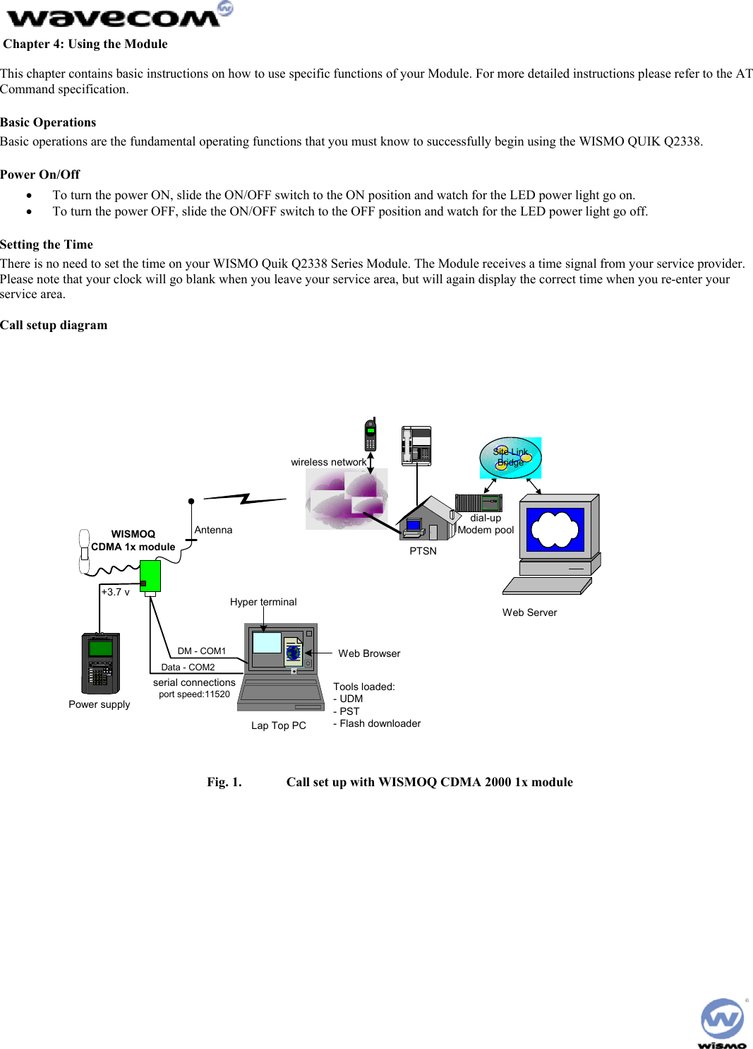
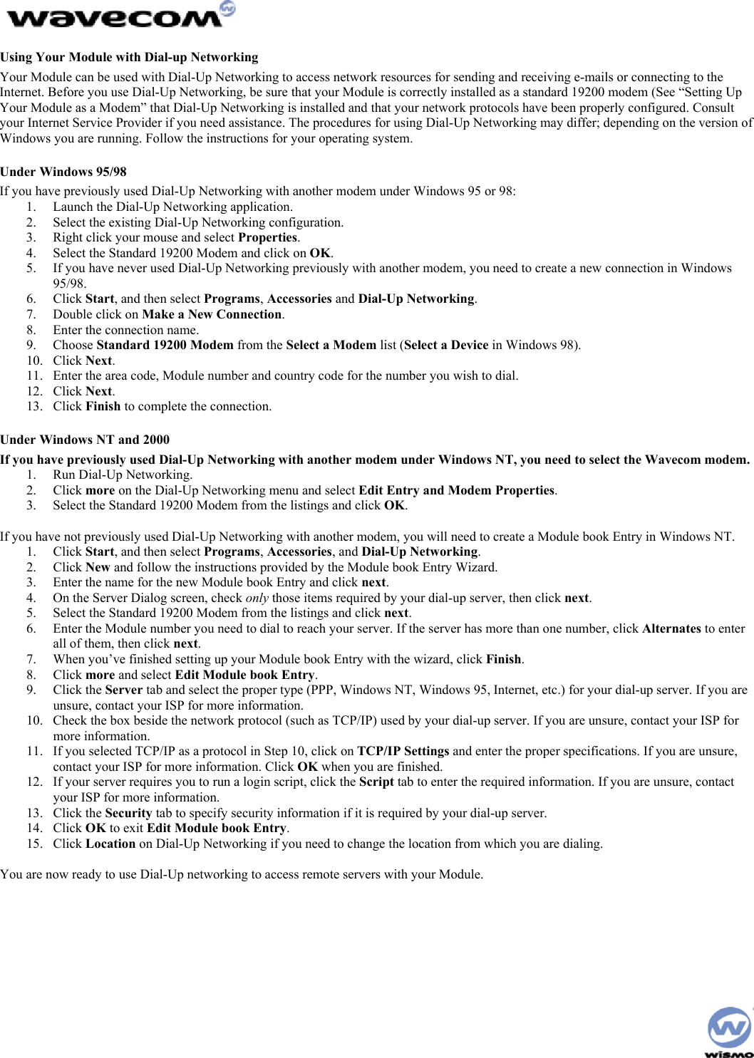
![Chapter 2: Starterkit Description Physical Description The WISMO QUIK Q2338 is 58 mm long, 32 mm wide and has a thickness of less than 5.9 mm. It weighs only XXX grams. The physical features of the WISMO QUIK Q2338 are identified in the following picture: Dimensions 58 x 32 x 5.9 mm Weight < 80 grams Volume Housing Aluminum Profiled [b3] Wismo Module [b4] Development Board The board diagram shows the relative position of all switches, connectors and jumpers that are discussed below. MODULEDMDB-9 DATADB-9SIMSOCKETRF HEADSET HANDSETHEADSETJTAGPOWERINPUTRESETSNGL/DIFFLED 1VIBRARINGEROFF/ONBOOTLED 2](https://usermanual.wiki/Sierra-Wireless/Q23X8001.Supplemental-Response-per-CRN-24412-revised-Users-Manual/User-Guide-288217-Page-9.png)
![Chapter 3: Unpacking & Setup the Module Unpacking the Module Your WISMO QUIK Q2338 package includes the following: • WISMO Quik Q2338 Series Module • WISMO Quik Development Board • AC/DC Power connector • (2) Serial Cables • Dual band Antenna • Antenna connector • CD-ROM: Which contains the User’s Guide (this manual), H/W and S/W specifications, and the AT Command document If you are missing any of these items, please return this package to your point of purchase and request a complete kit. The following gives a description of the connections and configurations required to bring up the Module. Be sure to consider these recommendations before applying power to the Interface Board and Module. Connecting the StarterKits To connect the StarterKits: 1. Connect the data port of the StarterKits to COM 2 of your PC or laptop using the DB9 serial cable. 2. Connect the dm port of the StarterKits to COM 1 of your PC or laptop using the DB9 serial cable. 3. Connect the AC/DC converter to an open wall socket at one end and the StarterKits at the other. Installing the WISMO Quik Module To install the WISMO: 1. Install the WISMO to the development board. Check the alignment of the board-to-board connector and the ground pins of the Module. 2. When the alignment is correct, firmly press on the WISMO until you hear a soft snap. 3. Insert the barrel jack connector of the power adapter plug into the power port on the development board. 4. Move the power switch to the on position. 5. Solder the four ground posts to the through holes in the PCB of the development board (Optional) When power is applied, the Module will illuminate and transition to a blinking LED [b5]](https://usermanual.wiki/Sierra-Wireless/Q23X8001.Supplemental-Response-per-CRN-24412-revised-Users-Manual/User-Guide-288217-Page-14.png)
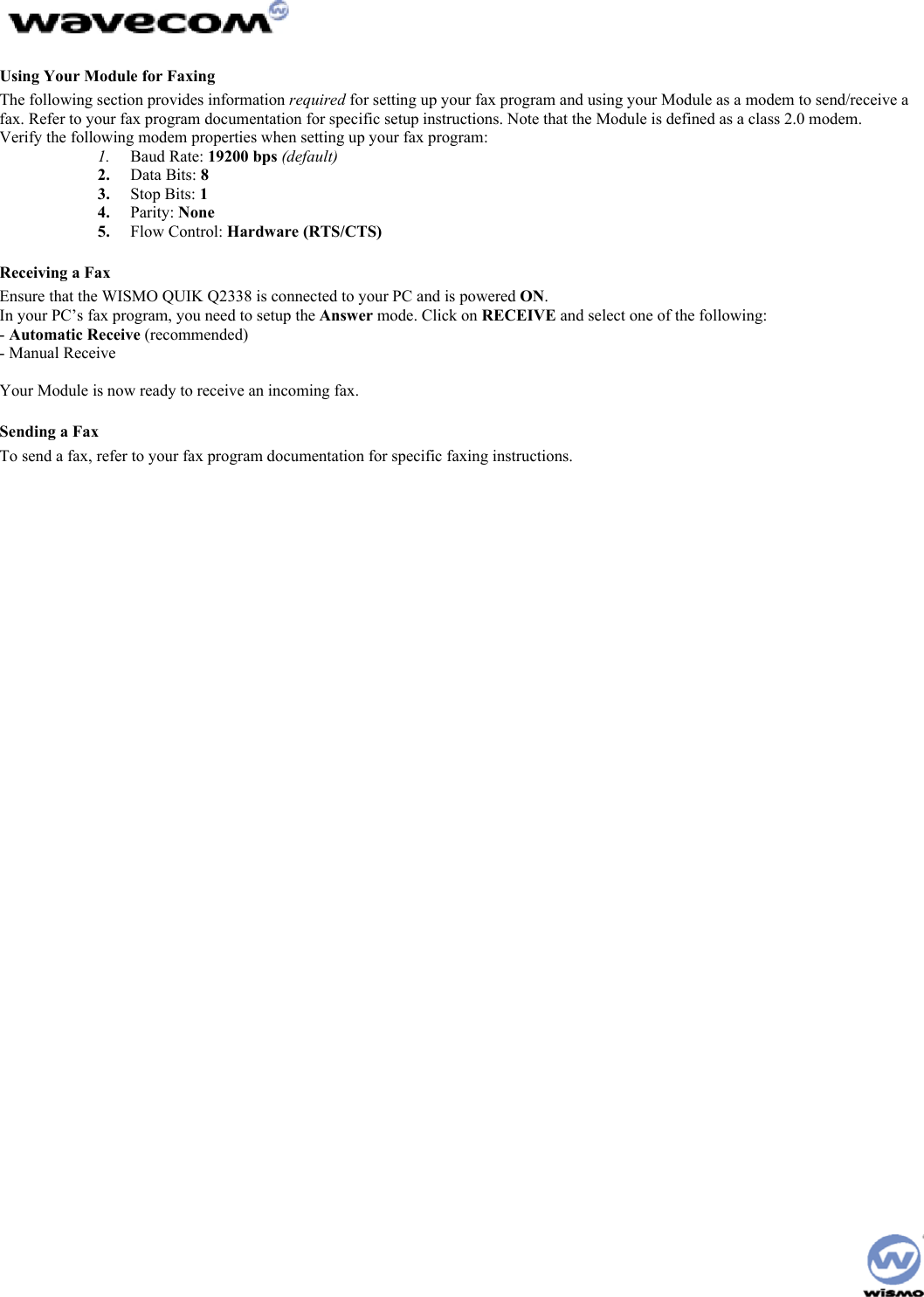
![Using Your Module for Data File Transfers The following section provides information required for setting up your data transfer program and use your Module as a modem to send/receive a data file. Refer to your data transfer program documentation for specific setup and data transfer instructions. Sending a Data File On Your Module: 1. Ensure that the WISMO QUIK Q2338 is connected to your PC and is powered ON. 2. Press [Preferences] (Soft Key 1). 3. Scroll to Features and press OK. 4. Scroll to Data/FAX and press OK. 5. Scroll through the choices using the Soft Keys until Data until Off is displayed with a check mark. Refer to your data transfer program documentation for specific instructions on receiving a data file. On Your PC/Laptop: 1. Start Procomm Plus™ in Data Terminal mode. Refer to the Procomm Plus documentation for specific instructions on how to use their software. 2. Select the COM port matching the serial port that your Module’s data cable is connected to. 3. Under Options> System Options> Modem Connection, click on the 4. Modem Connection Properties button and verify the settings as noted below: 5. Baud Rate: 19200 bps (default) • Data Bits: 8 • Stop Bits: 1 • Parity: None • Flow Control: Hardware (RTS/CTS) 6. Dial the number you wish to send a file to. 7. After a connection is established, select Data> Send File. 8. In the window that appears, locate and select the file you want to send. 9. Click on OK. The file transfer will begin. 10. After the file transfer is complete, select Data> Disconnect. The call will terminate. Receiving a Data File On Your Module: 1. Ensure that the WISMO QUIK Q2338 is connected to your PC and is powered ON. 2. .[b6] On Your PC/Laptop: 1. Start Procomm Plus in Data Terminal mode. Refer to the Procomm Plus documentation for specific instructions on how to use their software. 2. Select the COM port matching the serial port that your Module’s data cable is connected to. • Under Options> System Options> Modem Connection, click on the Modem Connection Properties button and verify the settings as noted below: • Baud Rate: 19200 bps (default) • Data Bits: 8 • Stop Bits: 1 • Parity: None • Flow Control: Hardware (RTS/CTS) 3. Dial the number or accept the incoming call from the number from which you will be receiving the file. 4. Select Data> Receive File. The file transfer will begin. 5. After the file transfer is complete, select Data> Disconnect. The call will terminate.](https://usermanual.wiki/Sierra-Wireless/Q23X8001.Supplemental-Response-per-CRN-24412-revised-Users-Manual/User-Guide-288217-Page-22.png)
![AT Commands Transferring data files may require you to use AT commands. The following tables list some of the more common AT Commands, S-Registers, and Basic Action Commands. For more AT commands, refer to your data transfer program documentation[b7]. [b8][b9]](https://usermanual.wiki/Sierra-Wireless/Q23X8001.Supplemental-Response-per-CRN-24412-revised-Users-Manual/User-Guide-288217-Page-23.png)
![Chapter 5: Care & Troubleshooting Caring for Your Module • Keep your Module clean. • Keep your Module dry. Humidity and liquids may cause your Module to fail and will corrode the internal circuits. • Protect your Module from temperature extremes. High temperatures may damage the batteries, shorten the life of electronic components, and warp or melt certain plastics. • Do not attempt to open or access the internal components of your Module. If your Module is not functioning properly, take it to the point of purchase. • Do not drop, shake, or handle your Module in a rough manner - it can damage the Module Cleaning Instructions 1. Turn the power off on your Module prior to cleaning. NOTE: Do not apply cleaning liquids directly to your Module. Avoid using harsh chemicals, strong detergents, and petroleum-based solvents to clean your Module. Some household cleaners contain chemicals that may damage your Module. 2. Apply the cleaning liquid to a soft cloth or towelette and gently wipe the external surfaces of your Module until it is clean. 3. Let the surfaces dry. 4. Turn the power on. 5. The Module is now ready to use. Basic Troubleshooting Techniques The following table describes possible problems and their resolution: The modem does not answer through the serial link 1. Is the modem correctly powered on? • If not, the correct power supply is 4V. 2. Is the serial cable suitable and adjusted in the modem and PC sockets? • A suitable cable must follow pin assignment described on figure 6. [b10]Check in particular, that Rx & Tx are properly connected. 3. Check that your communication program is properly configured: • Modem factory setting for the character framing are: • Data Bits: 8 • Parity: None • Stop Bits: 1 • The factory setting for baud rate is auto-bauding mode. 4. Does any other program interfere with your communication program (conflict on communication port access)? • If yes, close any application likely to interfere (e.g. mouse or printer driver). 5. Issue AT+CMEE=1 to have extended error cause and retry](https://usermanual.wiki/Sierra-Wireless/Q23X8001.Supplemental-Response-per-CRN-24412-revised-Users-Manual/User-Guide-288217-Page-24.png)
![[b11] No RF signal • Verify the Antenna is correctly connected to the Module. Verify the position of the Antenna is in a strong signal location. The Module does not answer through the serial link • No or incorrect power is being supplied to the Module. Verify the Power Supply and ON/OFF Switch position. • The Module is not adequately assembled onto the Interface Board. Verify that proper grounding (ideally solder) is provided. • The wrong DB-9 connector is being used. Verify that the DATA Port is connected to the controlling PC. • The terminal emulator application, HyperTerminal for example, is not correctly configured for the Module. Verify the Baud rate. It is possible that the Module has been configured for a different default Baud rate, so it may be necessary to try different rates in HyperTerminal. No audio • The wrong Audio Path has been selected. Try the other Audio Jack, or issue the AT Command to verify/select the correct path. • The SNGL/DIFF Jumper is not correctly installed. This only affects the Headset Audio Path.](https://usermanual.wiki/Sierra-Wireless/Q23X8001.Supplemental-Response-per-CRN-24412-revised-Users-Manual/User-Guide-288217-Page-25.png)