Sierra Wireless Q2426-SK GSM/GPRS Starter Kit Q2426B User Manual WISMO Quik Q2400 series
Sierra Wireless, Inc. GSM/GPRS Starter Kit Q2426B WISMO Quik Q2400 series
UserManual.wiki
>
Sierra Wireless
>
Q2426-SK User Manual
>
User Manual
Contents
1.
User Manual
2.
User Manual rev
3.
StarterKit
4.
UserMan rev
User Manual
Navigation menu
Upload a User Manual
Namespaces
Wiki Guide
HTML
PDF
Info
Views
User Manual
Discussion / Help
Navigation
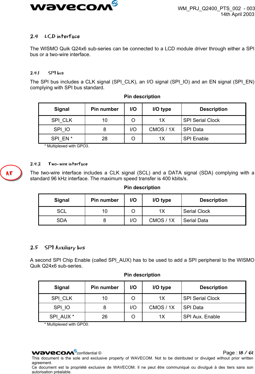
![WM_PRJ_Q2400_PTS_002 - 003 14th April 2003 Reference documents [1] WISMO Quik Q2400 Series Customer Design Guidelines WM_PRJ_Q2400_PTS_005 [2] WISMO Quik Q2400 Series Manufacturing Guide WM_PRJ_Q2400_PTS_006 [3] AT Commands Interface Guide WM_ASW_OAT_UGD_004 [4] Wavecom Acceptance and Verification Plan WAVE Plan, Release 1.4 [5] Q2406 or Q2426 delta with the Q2403 WM_PRJ_Q2400_PTS_004 confidential © Page : 8 / 61This document is the sole and exclusive property of WAVECOM. Not to be distributed or divulged without prior written agreement. Ce document est la propriété exclusive de WAVECOM. Il ne peut être communiqué ou divulgué à des tiers sans son autorisation préalable.](https://usermanual.wiki/Sierra-Wireless/Q2426-SK.User-Manual/User-Guide-340371-Page-8.png)
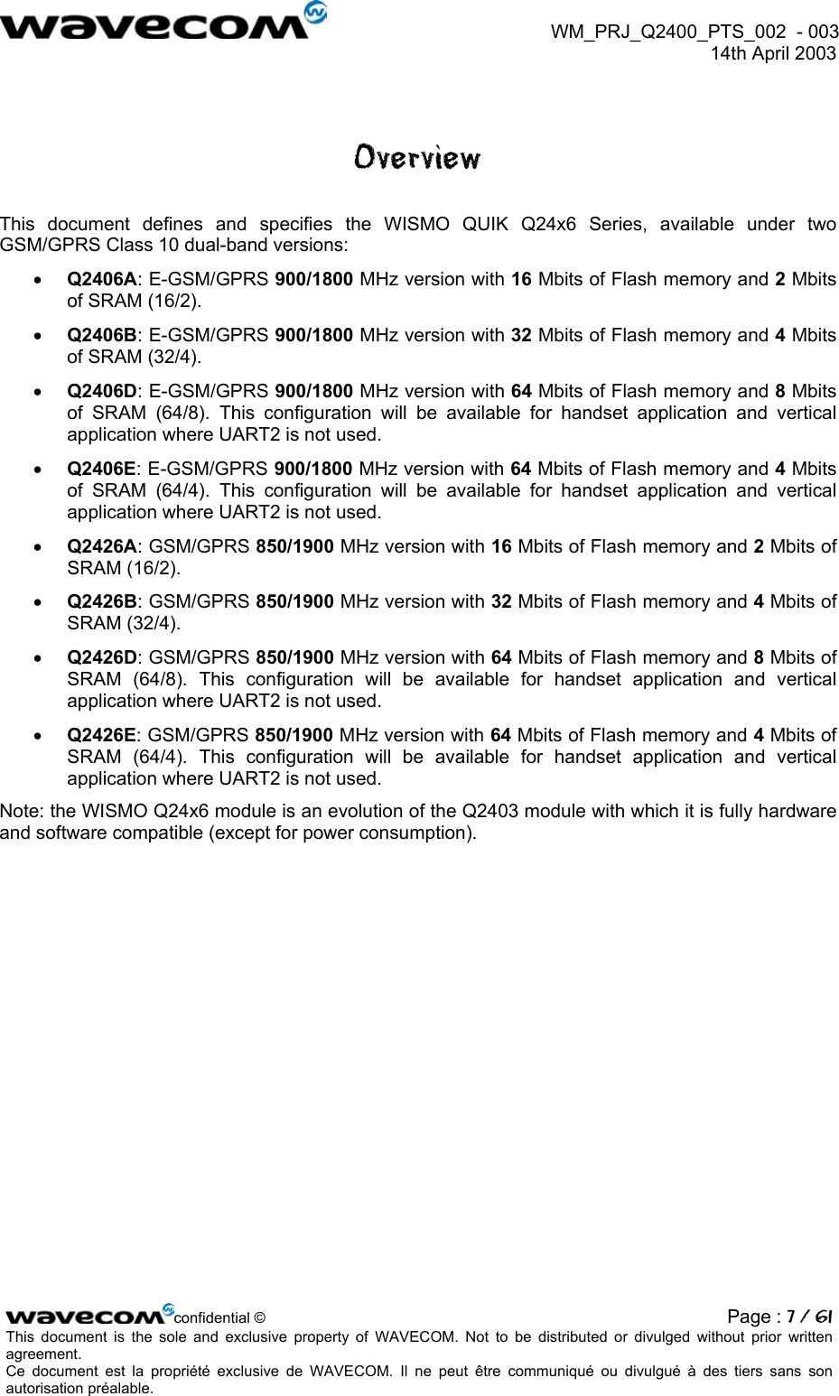
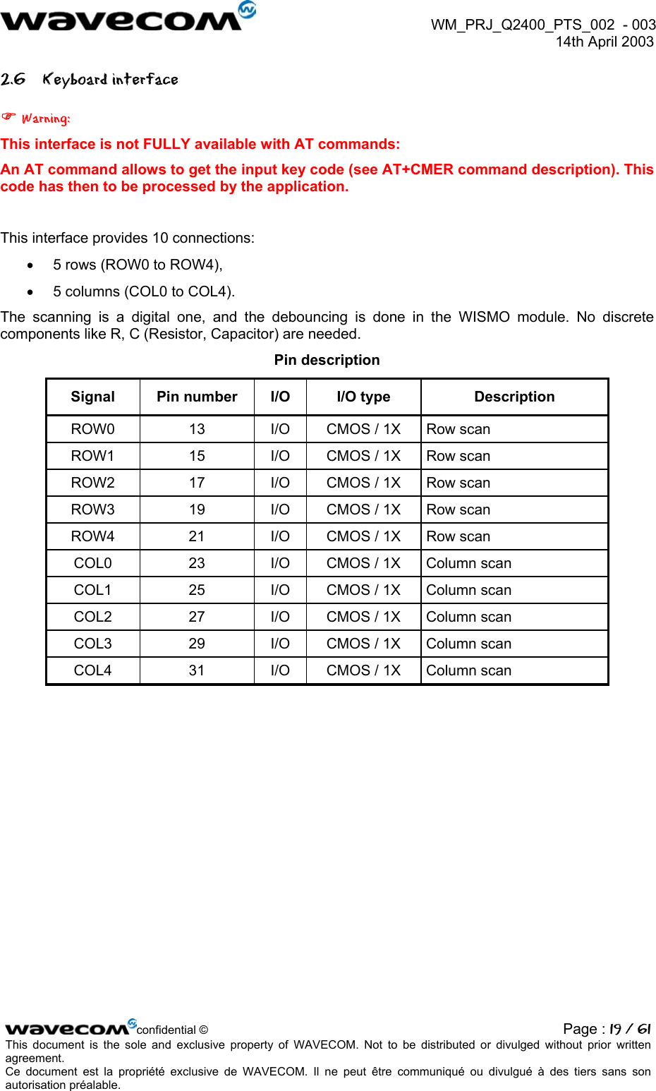
![WM_PRJ_Q2400_PTS_002 - 003 14th April 2003 1 General description 1.1 General information WISMO Quik Q24x6 sub-series is a range of self-contained E-GSM/GSM-GPRS 900/1800 or 850/1900 dual-band modules including the following features: • 58.4 x 32.2 x 3.9 mm. • 2 Watts E-GSM 900/GSM 850 radio section running under 3.6 Volts. • 1 Watt GSM1800/1900 radio section running under 3.6 Volts. • Digital section running under 2.8 Volts. • 3V only SIM interface (for 5 V SIM interface with external adaptation, refer to document [1]). • Real Time Clock with calendar. • Battery charge management. • Echo Cancellation + noise reduction. • Full GSM or GSM/GPRS software stack. • Hardware GPRS class 10 capable. • Complete shielding. • Complete interfacing through a 60-pin connector: o Power supply, o Serial link, o Audio, o SIM card interface, o Keyboard, o LCD (not available with AT commands). WISMO Quik Q24x6 sub-series has two external connections: • RF connection pads (to the antenna), • 60-pin General Purpose Connector (GPC) to Digital, Keyboard, Audio and Supply. WISMO Quik Q24x6 sub-series is designed to fit in very small terminals and only some custom functions have to be added to make a complete dual-band solution: • Keypad and LCD module, • Earpiece and Microphone, • Base connector, • Battery, • Antenna, • SIM connector. confidential © Page : 9 / 61This document is the sole and exclusive property of WAVECOM. Not to be distributed or divulged without prior written agreement. Ce document est la propriété exclusive de WAVECOM. Il ne peut être communiqué ou divulgué à des tiers sans son autorisation préalable.](https://usermanual.wiki/Sierra-Wireless/Q2426-SK.User-Manual/User-Guide-340371-Page-9.png)
![WM_PRJ_Q2400_PTS_002 - 003 14th April 2003 1.3 Firmware WISMO Quik Q24x6 sub-series is designed to be integrated into various types of applications such as handsets or vertical applications (telemetry, multimedia,…). For vertical applications, the firmware offers a set of AT commands to control the module (for further information, refer to document [3]). Please be aware that some of these interfaces can not be handled when using the WISMO Quik Q24x6 sub-series driven by AT commands: LCD interface, auxiliary serial link interface and SPI bus. This symbol is used to indicate the interfaces not available with AT commands. AAATTT These functions have then to be managed externally i.e using the main processor of the application. confidential © Page : 12 / 61This document is the sole and exclusive property of WAVECOM. Not to be distributed or divulged without prior written agreement. Ce document est la propriété exclusive de WAVECOM. Il ne peut être communiqué ou divulgué à des tiers sans son autorisation préalable.](https://usermanual.wiki/Sierra-Wireless/Q2426-SK.User-Manual/User-Guide-340371-Page-12.png)
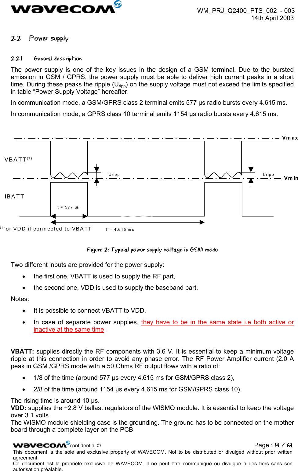
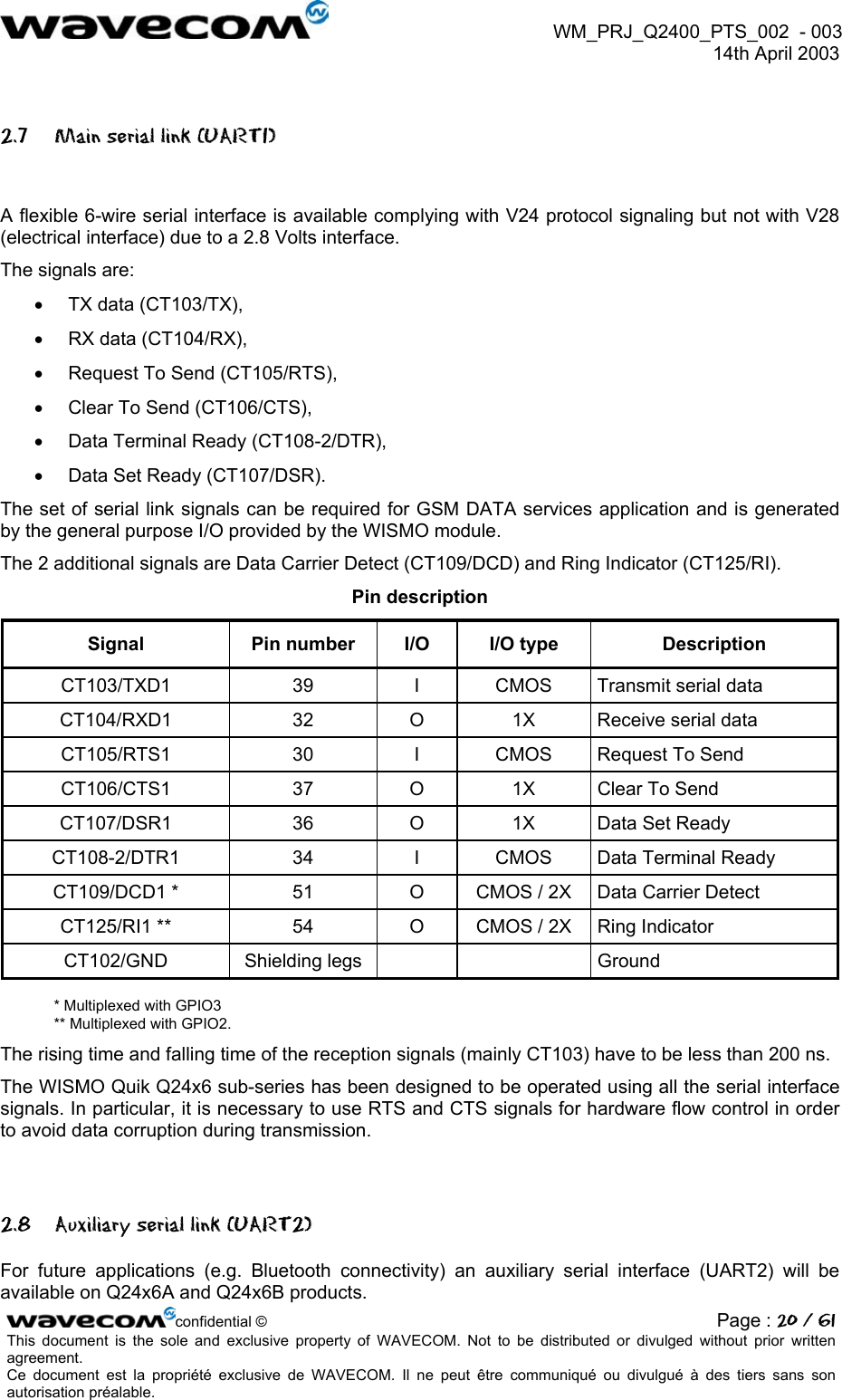
![WM_PRJ_Q2400_PTS_002 - 003 14th April 2003 Power Supply Voltage VMIN VNOM VMAX Ripple max (Uripp) VBATT 3.3 V (*) 3.6 V 4.5 V (**) 50 mVpp for freq<200 kHz 500 µVpp for freq>200 kHz VDD 3.1 V 4.5 V 100 mVpp (*): This value has to be guaranteed during the burst (with 2.0 A Peak in GSM or GPRS mode). (**): max operating Voltage Stationary Wave Ratio (VSWR) 2:1. When supplying the module with a battery, the total impedance (battery+contacts+protections+PCB) should be < 150 mOhms to limit voltage drop-out within emission burst. Refer to document [1] for further information about power supply design. 2.2.2 Power consumption The following information is given assuming a 50 Ω RF output. Power consumption in OFF mode (module supplied, OFF state, no software running) Conditions INOM IMAX Overall consumption VBATT + VDD Off 5 µA 10 µA confidential © Page : 15 / 61This document is the sole and exclusive property of WAVECOM. Not to be distributed or divulged without prior written agreement. Ce document est la propriété exclusive de WAVECOM. Il ne peut être communiqué ou divulgué à des tiers sans son autorisation préalable.](https://usermanual.wiki/Sierra-Wireless/Q2426-SK.User-Manual/User-Guide-340371-Page-15.png)

![WM_PRJ_Q2400_PTS_002 - 003 14th April 2003 Warning: The auxiliary serial link (UART2) is not available on Q24x6D and Q24x6E products (version with 64 Mbits of Flash memory). Pin description Signal Pin number I/O I/O type Description Multiplexed with CT103 / TXD2 18 I 3X Receive serial data GPI CT104 / RXD2 20 O CMOS Transmit serial data GPO2 CT106 / CTS2 24 I CMOS Clear To Send GPIO0 CT105 / RTS2 35 O 2X Request To Send GPIO5 2.9 SIM interface 2.9.1 General Description 5 signals are available: • SIM_VCC: SIM power supply. • SIM_RST: reset. • SIM_CLK: clock. • SIM_DATA: I/O port. • SIM_PRES: SIM card detect. The SIM interface controls a 3 V SIM card (and a 5 V SIM card through an external SIM driver, refer to document [1] for more details). This interface is fully compliant with GSM 11.11 recommendations concerning SIM functions. Pin description Signal Pin number I/O I/O type Description SIM_CLK 3 O 2X SIM Clock SIM_RST 5 O 2X SIM Reset SIM_DATA 7 I/O CMOS / 3X SIM Data SIM_VCC 9 O SIM Power Supply SIM_PRES 50 I CMOS SIM Card Detect confidential © Page : 21 / 61This document is the sole and exclusive property of WAVECOM. Not to be distributed or divulged without prior written agreement. Ce document est la propriété exclusive de WAVECOM. Il ne peut être communiqué ou divulgué à des tiers sans son autorisation préalable.](https://usermanual.wiki/Sierra-Wireless/Q2426-SK.User-Manual/User-Guide-340371-Page-21.png)
![WM_PRJ_Q2400_PTS_002 - 003 14th April 2003 Electrical Characteristics Parameter Conditions Min Typ Max Unit SIM_DATA VIH IIH = ± 20 µA 0.7xSIM_VCC V SIM_DATA VIL IIL = 1 mA 0.3xSIM_VCC V SIM_RST, SIM_DATA SIM_CLK VOH Source current = 20 µA SIM_VCC – 0.1V V SIM_RST, SIM_DATA SIM_CLK VOL Sink current = -200 µA 0.1 V SIM_VCC* Output Voltage ISIMVCC <= 6 mA 2.70 2.80 2.85 V SIM_CLK Rise/Fall Time Loaded with 30 pF 50 ns SIM_RST, SIM_DATA Rise/Fall Time Loaded with 30 pF 1 µs SIM_CLK Frequency Loaded with 30 pF 3.25 MHz (*): given for a 3 V interface. An external SIM driver is needed to handle 5 V SIMs. Note for SIM_PRES connection: • When not used SIM_PRES has to be tied to VCC. • When used, a low to high transition means that the SIM card is inserted and a high to low transition means that the SIM card is removed. 2.9.2 SIM 3/5V management The WISMO Quik Q24x6 sub-series module is designed to interface with 3 V SIMs only1. Nevertheless, it is possible to manage 3 V and 5 V SIM cards using an external level shifter (refer to customer design guidelines [1]). In this case, depending on the type of SIM detected, the module firmware triggers the GPO0 output signal (pin #26) in order to properly set the external SIM driver level (3V or 5V). confidential © Page : 22 / 61This document is the sole and exclusive property of WAVECOM. Not to be distributed or divulged without prior written agreement. Ce document est la propriété exclusive de WAVECOM. Il ne peut être communiqué ou divulgué à des tiers sans son autorisation préalable. 1 Most of the GSM operators have been providing 3 V SIMs since 1998.](https://usermanual.wiki/Sierra-Wireless/Q2426-SK.User-Manual/User-Guide-340371-Page-22.png)
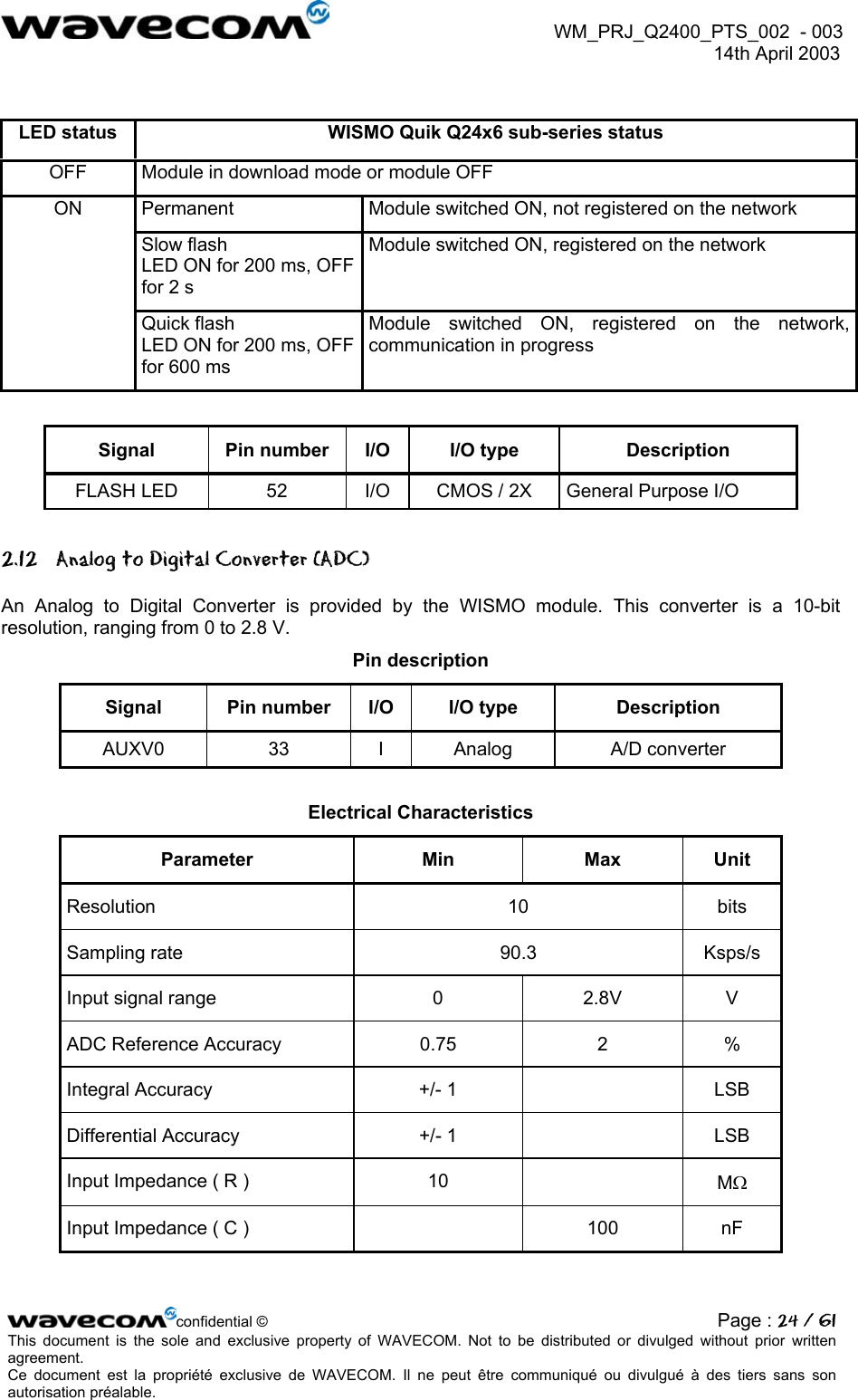
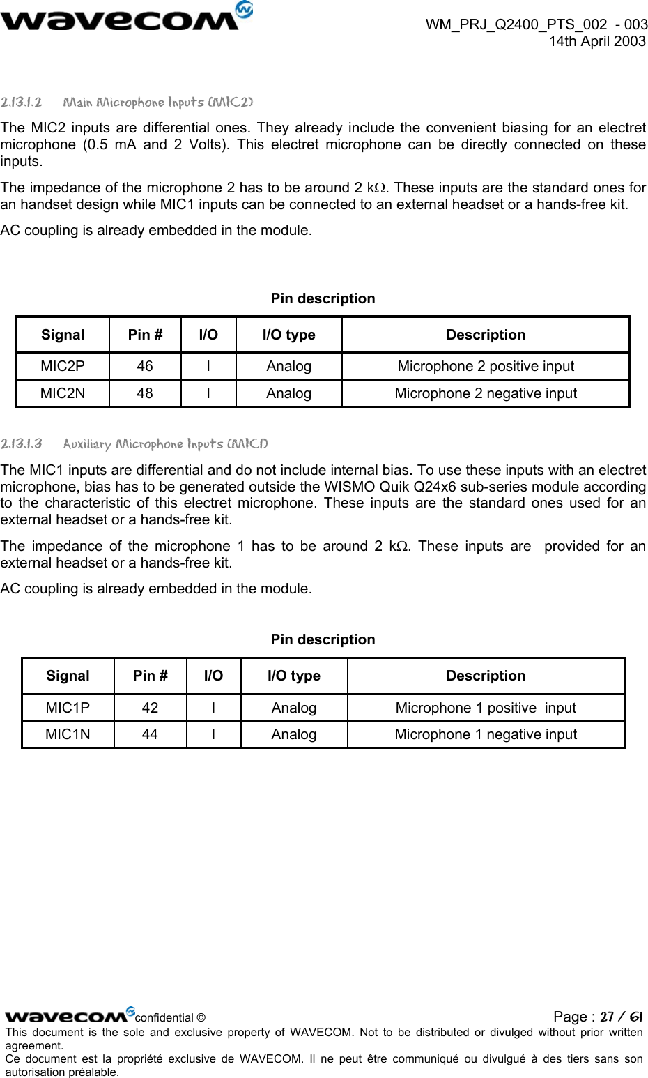
![WM_PRJ_Q2400_PTS_002 - 003 14th April 2003 2.13 Audio interface Two different microphone inputs and two different speaker outputs are supported. The WISMO Quik Q24x6 sub-series also includes an echo cancellation feature which allows hands-free function. In some case, ESD protection must be added on the audio interface lines. 2.13.1 Microphone inputs The MIC2 inputs already include the biasing for an electret microphone allowing an easy connection to a handset. The MIC1 inputs do not include an internal bias. MIC1/SPK1 is then appropriate for a hands-free system or a handset with biasing external to the module. 2.13.1.1 Common microphone inputs characteristics The connection can be either differential or single-ended but using a differential connection in order to reject common mode noise and TDMA noise is strongly recommended. When using a single-ended connection, be sure to have a very good ground plane, a very good filtering as well as shielding in order to avoid any disturbance on the audio path. Internal audio filter characteristics Frequency Gain 0-150 Hz < -22 dB 150-180 Hz < -11 dB 180-200 Hz < -3 dB 200-3700 Hz 0 dB >4000 Hz < -60 dB The gain of MIC inputs is internally adjusted and can be tuned from 30 dB to 51 dB using an AT command (refer to AT commands documentation [3]). confidential © Page : 25 / 61This document is the sole and exclusive property of WAVECOM. Not to be distributed or divulged without prior written agreement. Ce document est la propriété exclusive de WAVECOM. Il ne peut être communiqué ou divulgué à des tiers sans son autorisation préalable.](https://usermanual.wiki/Sierra-Wireless/Q2426-SK.User-Manual/User-Guide-340371-Page-25.png)
![WM_PRJ_Q2400_PTS_002 - 003 14th April 2003 Microphone gain vs Max input voltage (using controller 1*) Transmit Gain (dB) Max Vin (mVrms) +30 43.80 +33 31.01 +36 21.95 +39 15.54 +42 11 +45 7.79 +48 5.51 +51 3.9 (*) for more details, refer to AT commands documentation [3] Microphone gain vs Max input voltage (using controller 2*) Transmit Gain (dB) Max Vin (mVrms) - 6.5 3031 -6.0 2861 … … 0.0 1434 … … +9.5 480 +10.0 454 + 30.3 43.80 + 30.8 41.36 … … + 50.8 4.14 + 51.3 3.90 (*) for more details, refer to AT commands documentation [3] confidential © Page : 26 / 61This document is the sole and exclusive property of WAVECOM. Not to be distributed or divulged without prior written agreement. Ce document est la propriété exclusive de WAVECOM. Il ne peut être communiqué ou divulgué à des tiers sans son autorisation préalable.](https://usermanual.wiki/Sierra-Wireless/Q2426-SK.User-Manual/User-Guide-340371-Page-26.png)
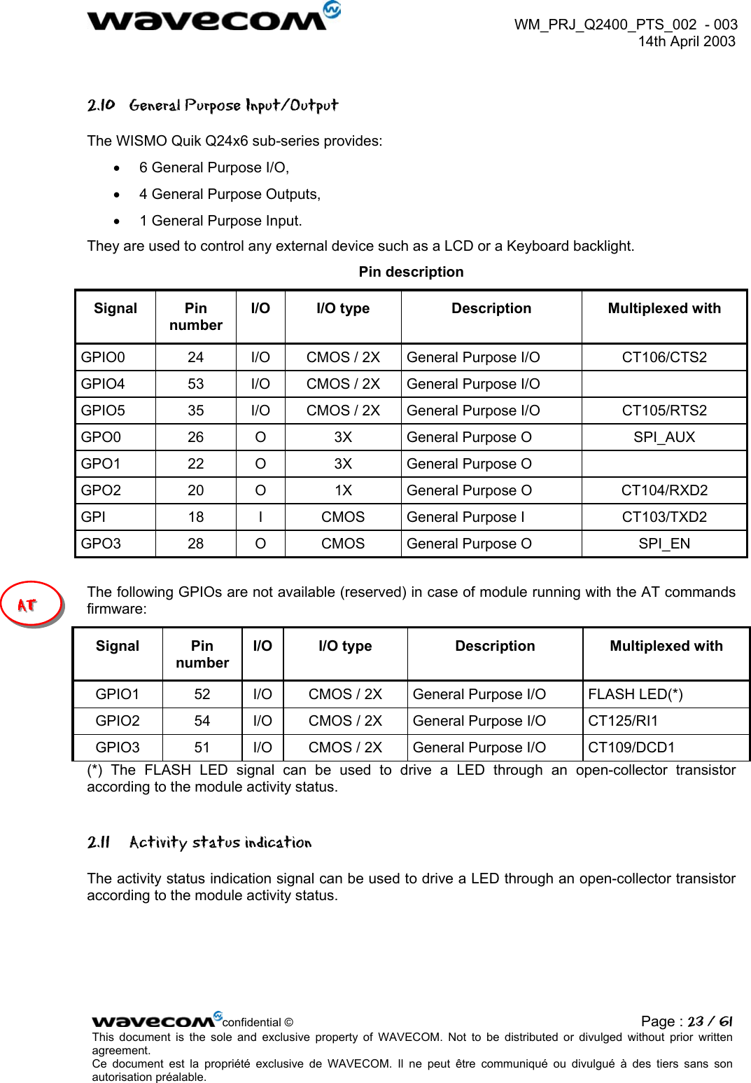
![WM_PRJ_Q2400_PTS_002 - 003 14th April 2003 2.15.2.2 Power OFF To properly power OFF the module, the application must set the ON/~OFF signal to low and then send the AT+CPOF command to de-register from the network and switch off the module. Once the « OK » response is issued by the module, the power supply can be switched off. POW ER SUPPLYON/~OFFAT COM M ANDST A TE OF TH E M OD ULEAT+CPOFModule READY Module OFFIBB+ RF<100 µA Netw ork dependentOK response IBB+RF = overall current consumption (Base Band + RF part) Figure 4: Power-OFF sequence diagram 2.16 BOOT (optional) This input can be used to download a software in the Flash memory of the WISMO module. For the applications based on AT commands, this is a backup download procedure only (refer to document [1] Customer Design Guidelines). The internal boot procedure is started when this pin is low during the reset of the module. In normal mode this pin has to be left open. In Internal boot mode, low level has to be set through a 1KΩ resistor. If used, this input has to be driven by an open collector or an open drain output: • BOOT pin 12 = 0, for download mode, • BOOT pin 12 = 1, for normal mode. Pin description Signal Pin number I/O I/O type Description BOOT 12 I CMOS Flash Downloading Note : The nominal firmware download procedure is using the X-modem confidential © Page : 34 / 61This document is the sole and exclusive property of WAVECOM. Not to be distributed or divulged without prior written agreement. Ce document est la propriété exclusive de WAVECOM. Il ne peut être communiqué ou divulgué à des tiers sans son autorisation préalable.](https://usermanual.wiki/Sierra-Wireless/Q2426-SK.User-Manual/User-Guide-340371-Page-34.png)
![WM_PRJ_Q2400_PTS_002 - 003 14th April 2003 2.17.2 Reset sequence To activate the « emergency » reset sequence, the ~RST signal has to be set to low for 500 µs minimum. As soon as the reset is complete, the AT interface answers « OK » to the application. For this, the application has to send AT↵. If the application manages hardware flow control, the AT command can be sent during the initialisation phase. Another solution is to use the AT+WIND command to get an unsollicited status from the module. For further details, refer to AT commands documentation [3]. RESET m od eIBB+ RF=20 to 40 mA EXTERN A L RSTST A TE OF TH E M OD ULEModule READYM in:500 µs Typ:2 m s AT answ ers “OK”Module READY SIM and netw ork dependentModule ONIBB+ RF<120 m A w ithout loc update Figure 5: Reset sequence diagram 2.18 External Interrupt (~INTR) The WISMO module provides an external interrupt input ~INTR. This input is very sensitive and an interrupt is activated on high to low edge. If this signal is not used it can be left open. If used this input has to be driven by an open collector or an open drain output. This input is used for instance to power OFF automatically the module. Pin description Signal Pin number I/O I/O type Description ~INTR 16 I CMOS External Interrupt Electrical characteristics Parameter Min Max Unit VIL -0.5 0.7 Volt VIH 2.2 3.0 Volt confidential © Page : 36 / 61This document is the sole and exclusive property of WAVECOM. Not to be distributed or divulged without prior written agreement. Ce document est la propriété exclusive de WAVECOM. Il ne peut être communiqué ou divulgué à des tiers sans son autorisation préalable.](https://usermanual.wiki/Sierra-Wireless/Q2426-SK.User-Manual/User-Guide-340371-Page-36.png)
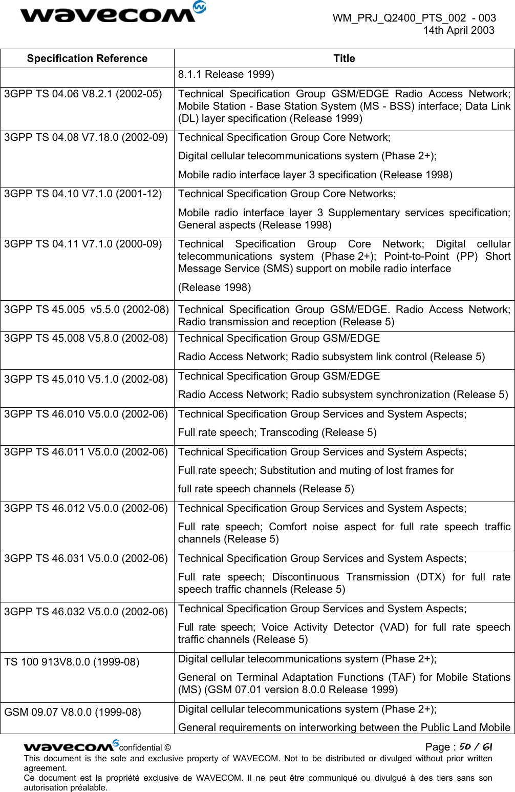
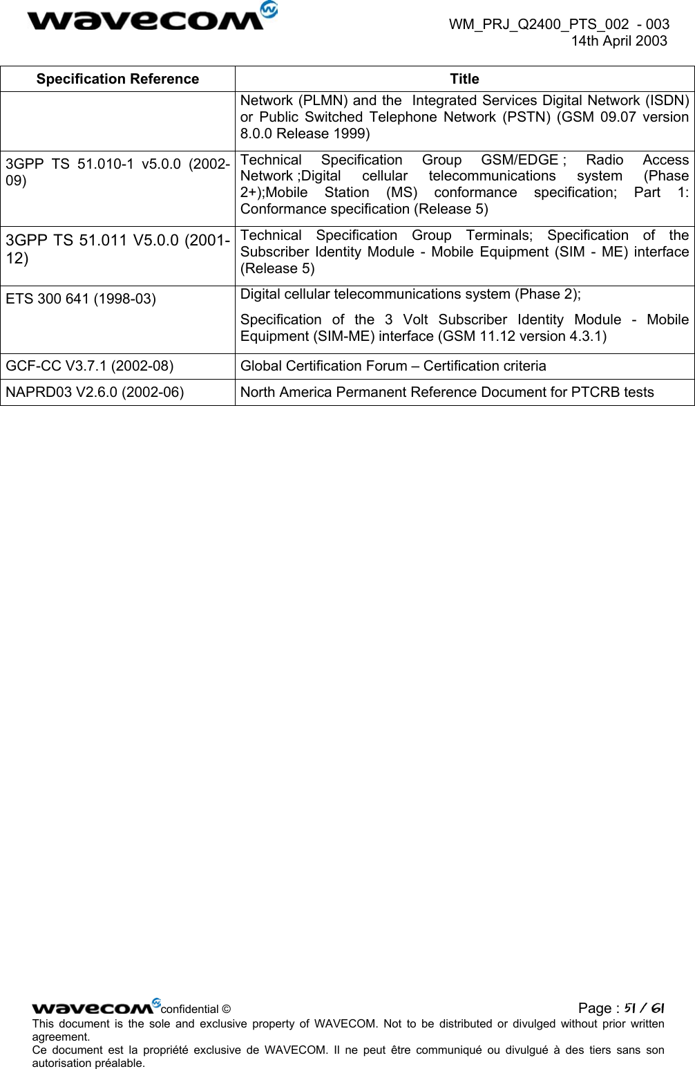
![WM_PRJ_Q2400_PTS_002 - 003 14th April 2003 4 Appendix 4.1 Wavecom acceptance test The WISMO Quik Q24x6 sub-series complies with Wavecom standard acceptance test plan (Refer to document [4]). 4.2 GSM Standard and Recommendations The WISMO Quik Q24x6 sub-series is compliant with the following GSM ETSI, 3GPP, GCF and NAPRD03 recommendations for Phase II. Specification Reference Title 3GPP TS 45.005 v5.5.0 (2002-08) Release 5 Technical Specification Group GSM/EDGE. Radio Access Network; Radio transmission and reception GSM 02.07 V8.0.0 (1999-07) Digital cellular telecommunications system (Phase 2+); Mobile Stations (MS) features (GSM 02.07 version 8.0.0 Release 1999) GSM 02.60 V8.1.0 (1999-07) Digital cellular telecommunications system (Phase 2+); General Packet Radio Service (GPRS); Service description, Stage 1 (GSM 02.60 version 8.1.0 Release 1999) GSM 03.60 V7.9.0 (2002-09) Technical Specification Group Services and System Aspects; Digital cellular telecommunications system (Phase 2+); General Packet Radio Service (GPRS); Service description; Stage 2 (Release 1998) 3GPP TS 43.064 V5.0.0 (2002-04) Technical Specification Group GERAN; Digital cellular telecommunications system (Phase 2+); General Packet Radio Service (GPRS); Overall description of the GPRS radio interface; Stage 2 (Release 5) 3GPP TS 03.22 V8.7.0 (2002-08) Technical Specification Group GSM/EDGE. Radio Access Network; Functions related to Mobile Station (MS) in idle mode and group receive mode; (Release 1999) 3GPP TS 03.40 V7.5.0 (2001-12) Technical Specification Group Terminals; Technical realization of the Short Message Service (SMS) (Release 1998) 3GPP TS 03.41 V7.4.0 (2000-09) Technical Specification Group Terminals; Technical realization of Cell Broadcast Service (CBS) (Release 1998) ETSI EN 300 903 V8.1.1 (2000-11) Digital cellular telecommunications system (Phase 2+); Transmission planning aspects of the speech service in the GSM Public Land Mobile Network (PLMN) system (GSM 03.50 version confidential © Page : 49 / 61This document is the sole and exclusive property of WAVECOM. Not to be distributed or divulged without prior written agreement. Ce document est la propriété exclusive de WAVECOM. Il ne peut être communiqué ou divulgué à des tiers sans son autorisation préalable.](https://usermanual.wiki/Sierra-Wireless/Q2426-SK.User-Manual/User-Guide-340371-Page-49.png)