Sierra Wireless Q2438 CDMA 850 / 1900 MHz Modem User Manual Raven and PinPoint CDMA User Guide
Sierra Wireless, Inc. CDMA 850 / 1900 MHz Modem Raven and PinPoint CDMA User Guide
Contents
- 1. Users Manual
- 2. Users Manual per CRN 10515
- 3. Raven and Pinpoint
- 4. Redwing
Raven and Pinpoint
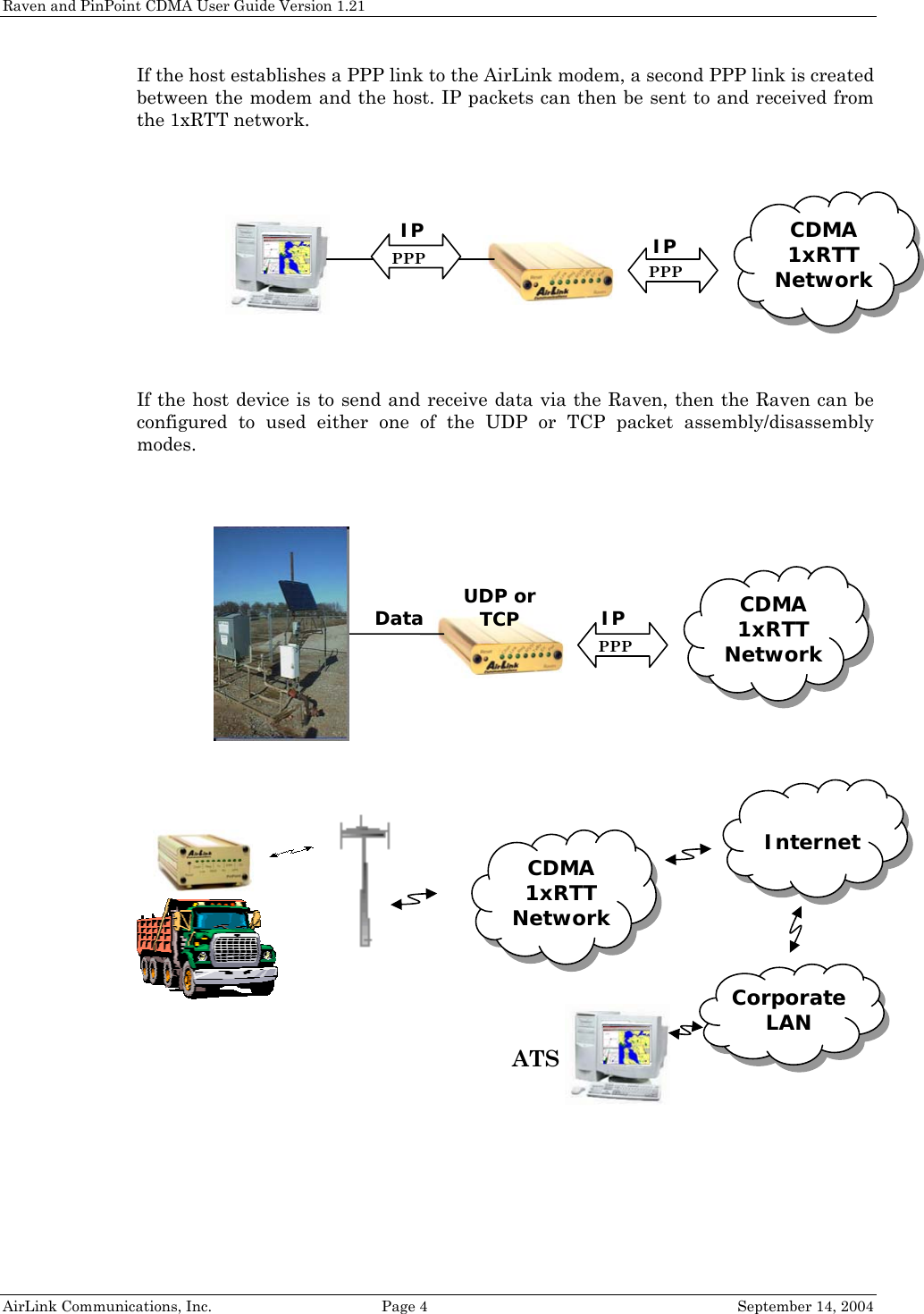
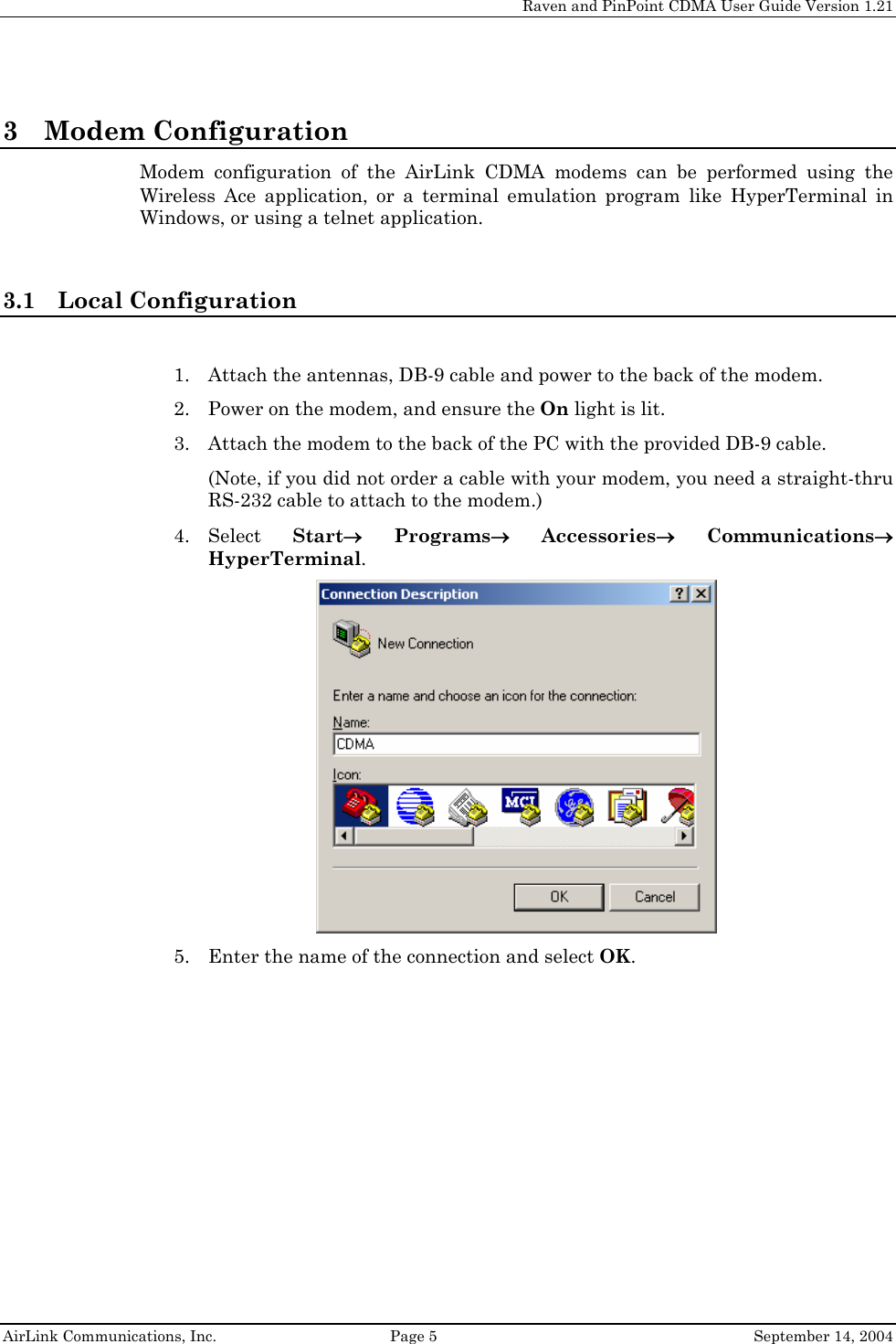
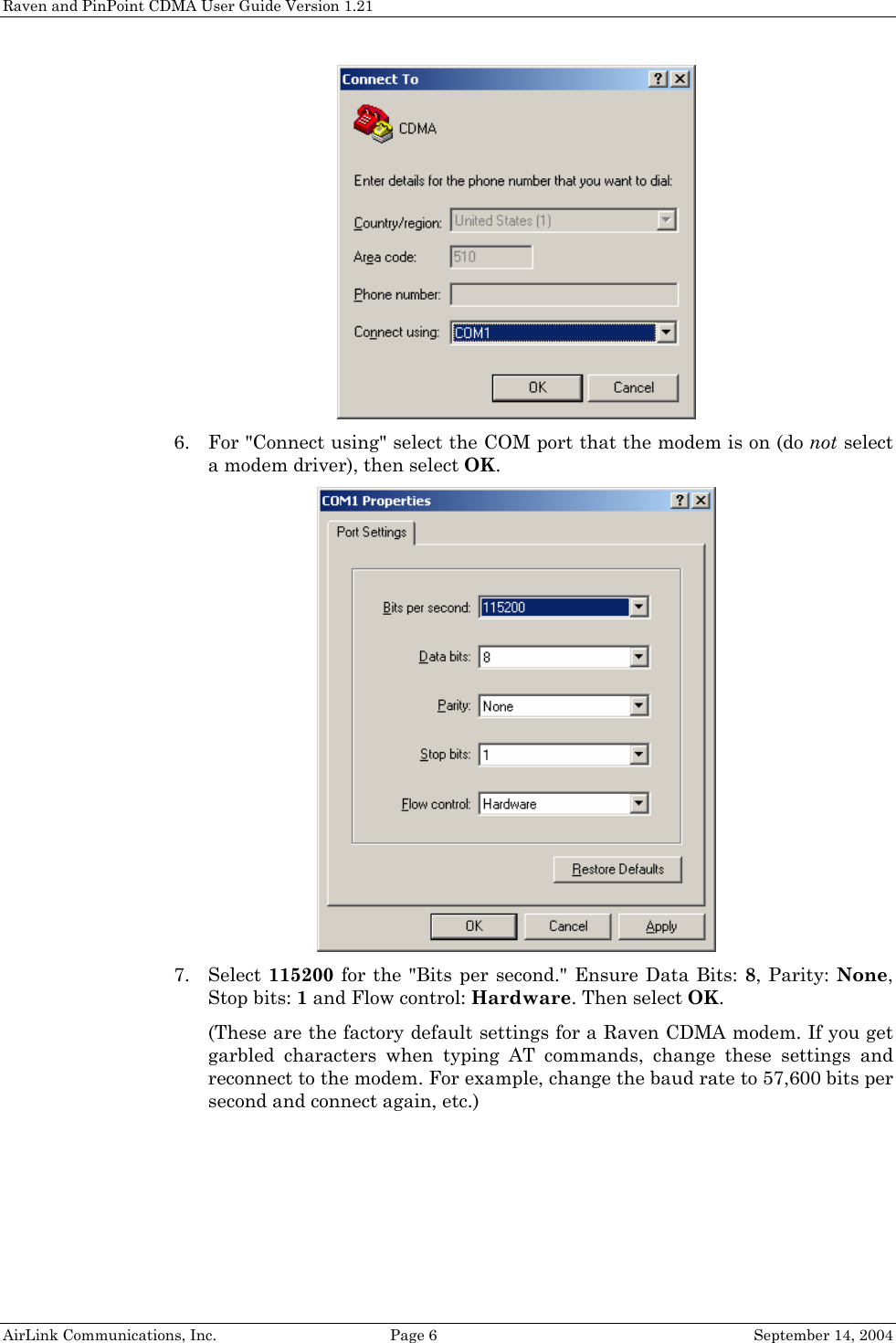
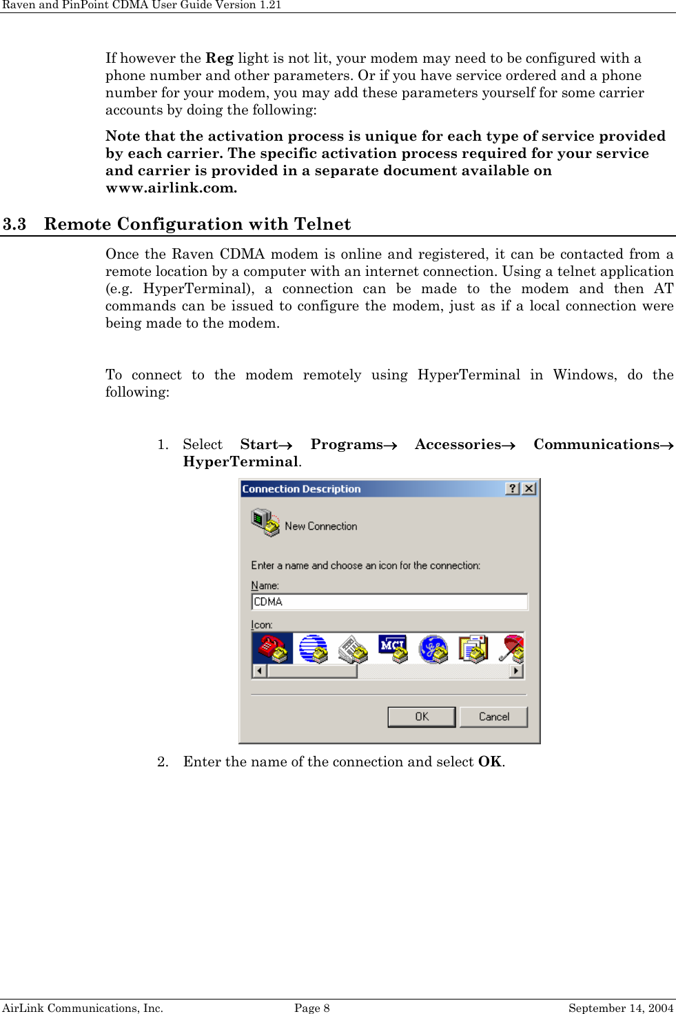
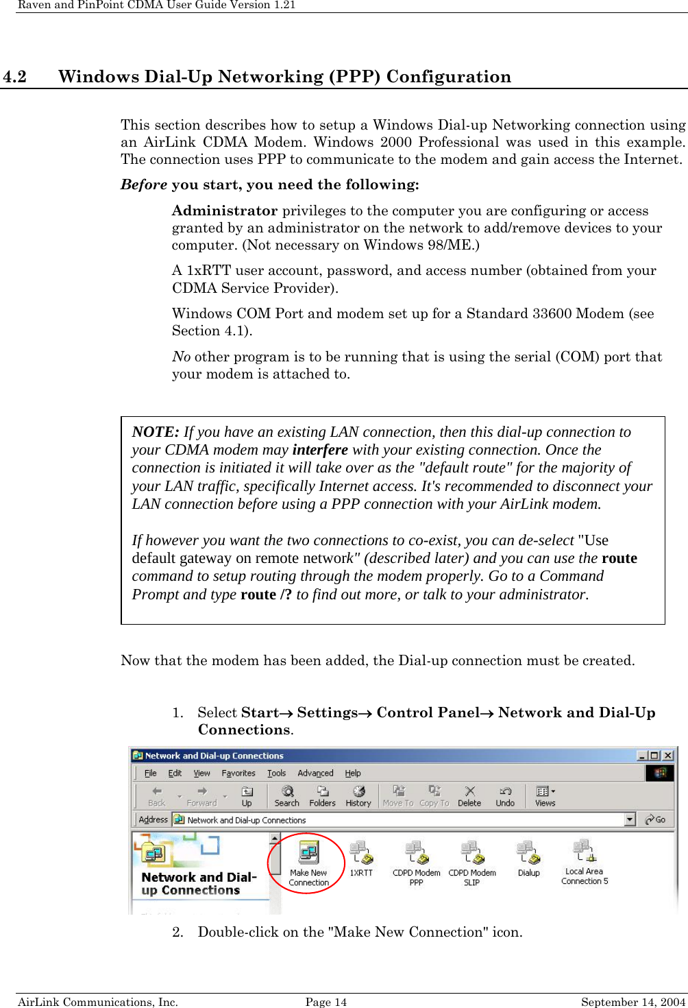
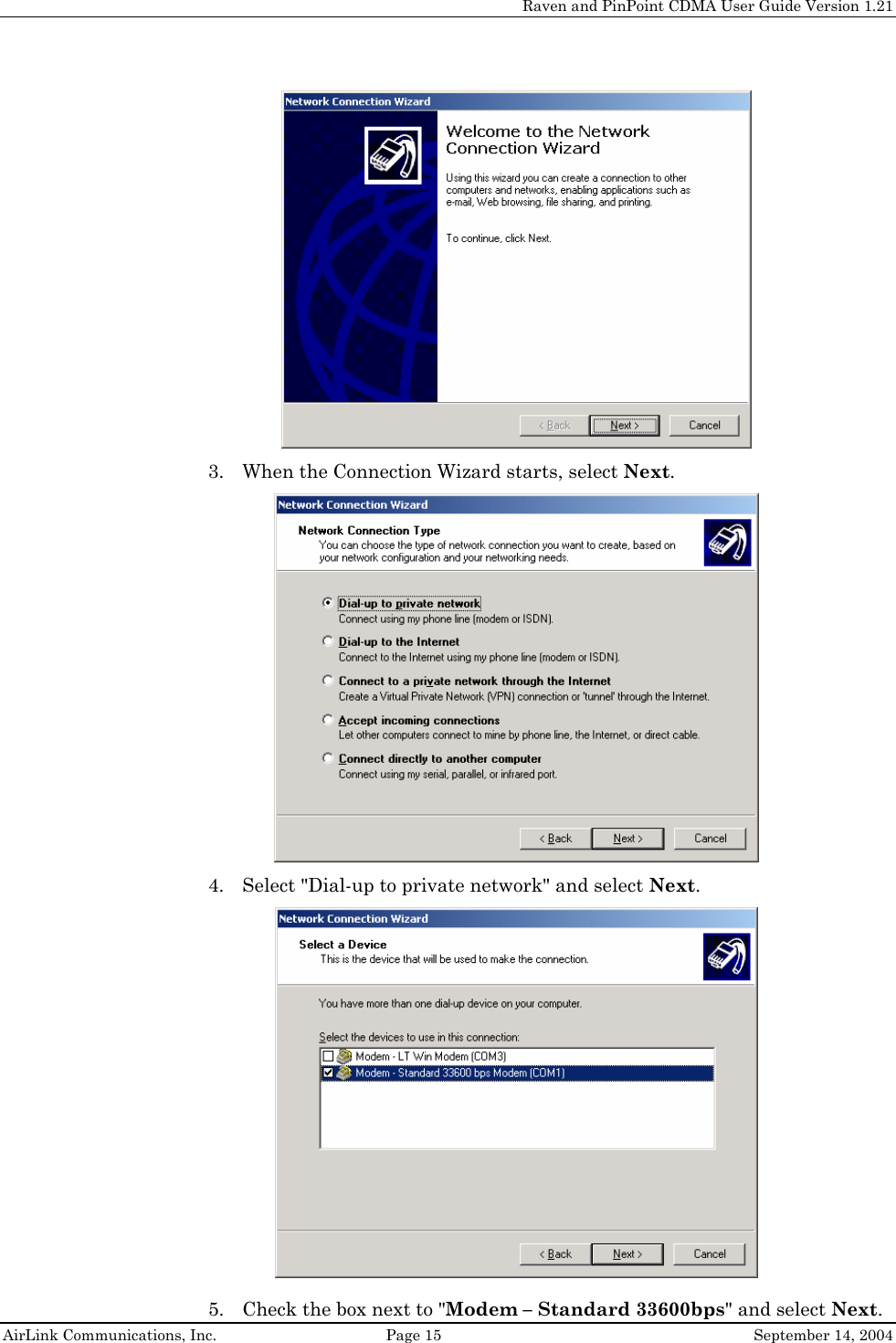
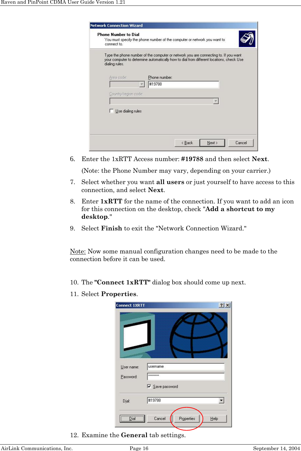
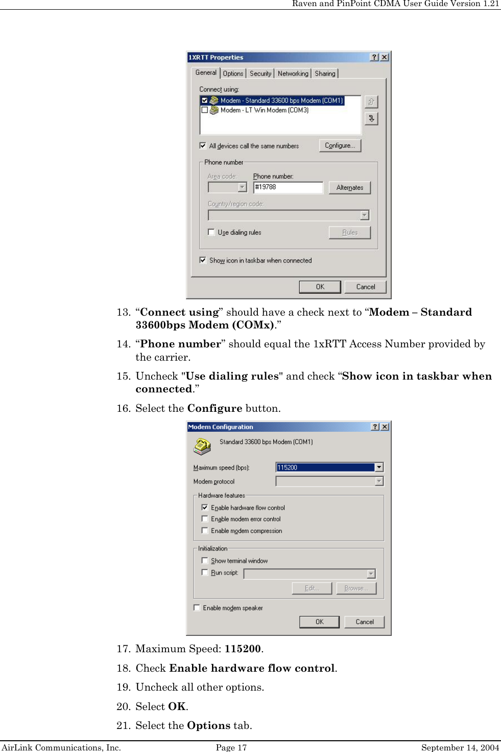
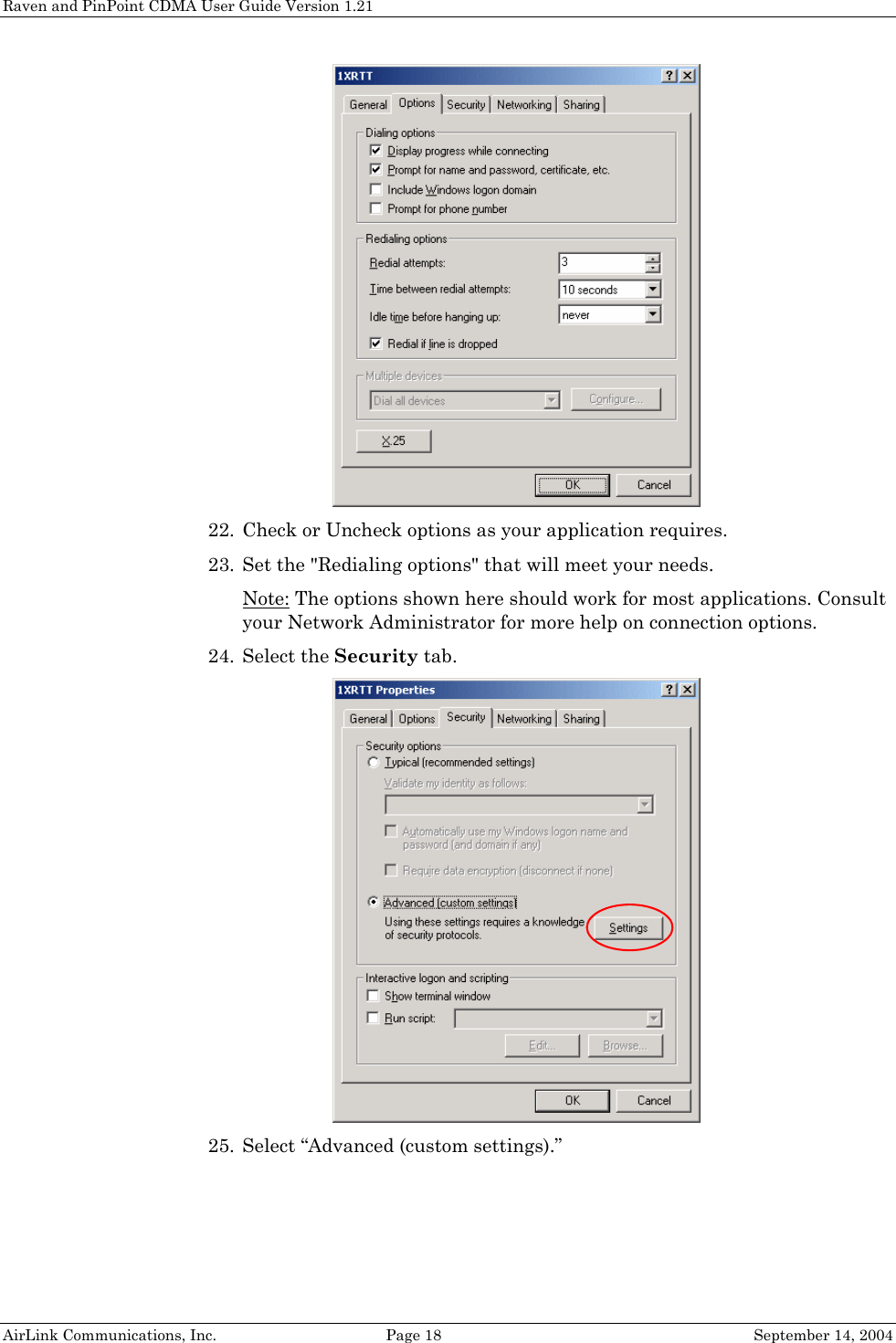
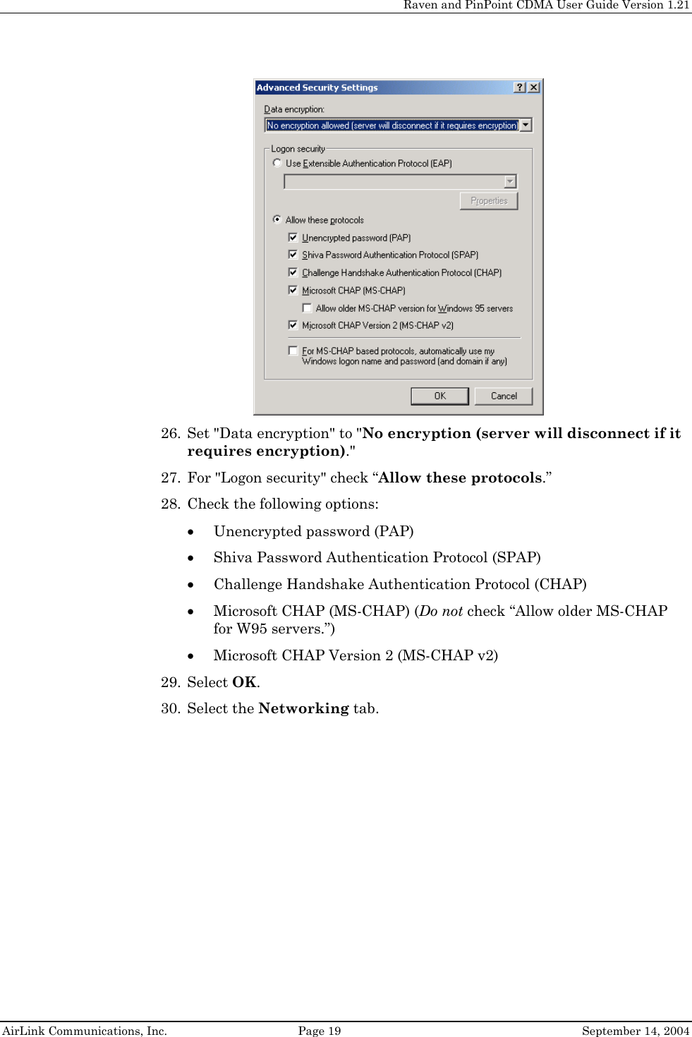
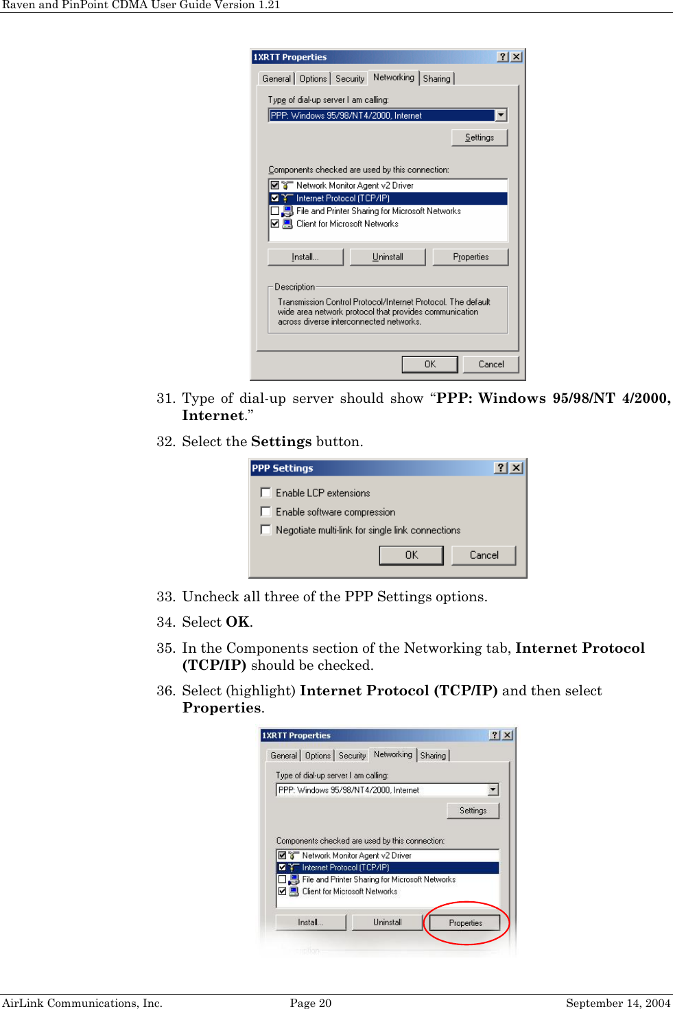
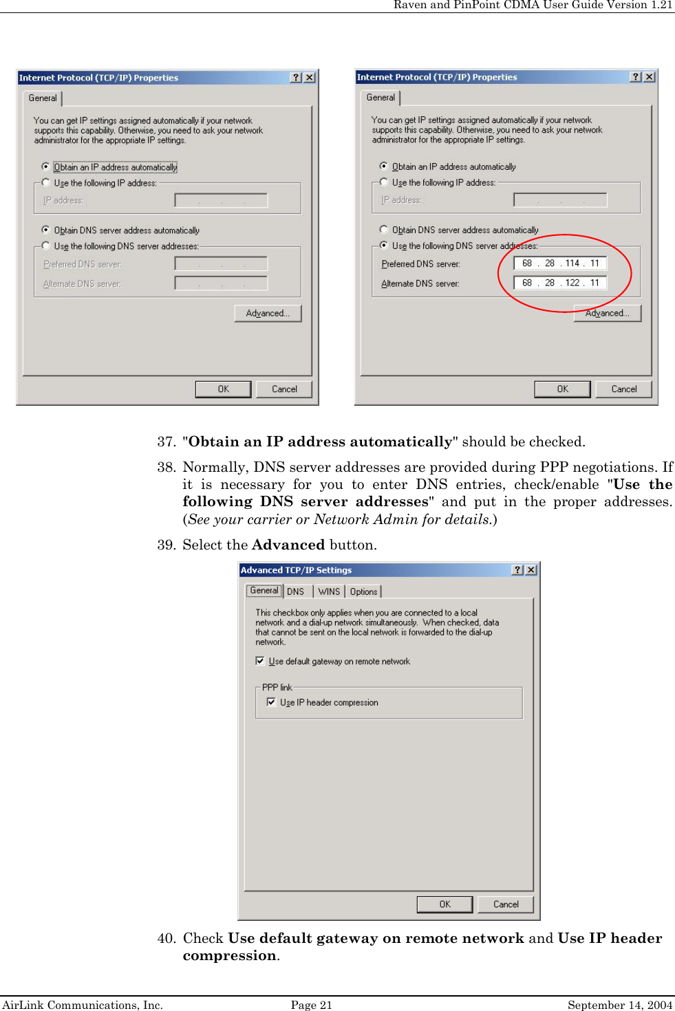
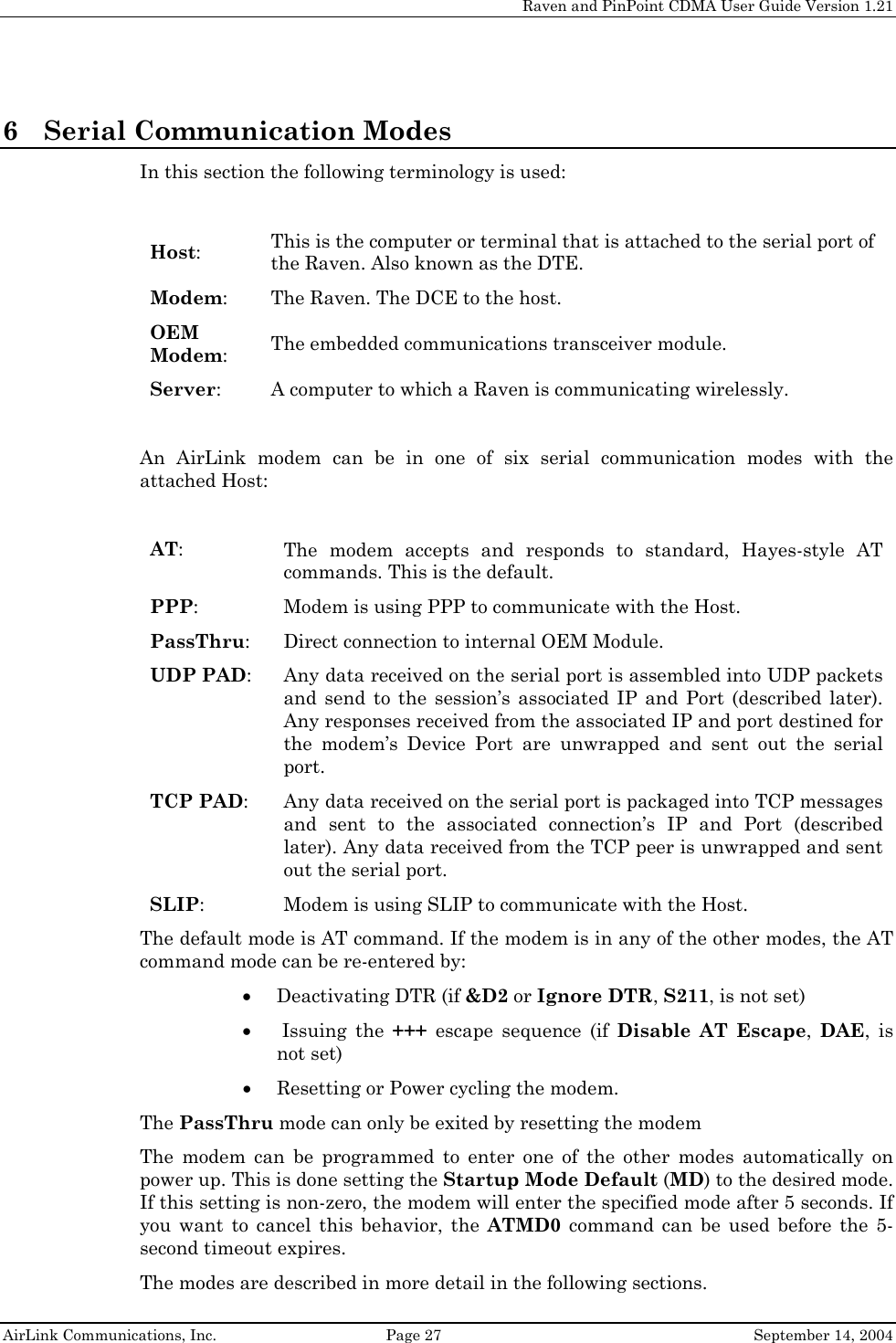
![Raven and PinPoint CDMA User Guide Table of Contents 1 Introduction ..................................................................................... 1 1.1 Raven Product Overview ............................................................................... 2 1.2 PinPoint Product Overview........................................................................... 2 2 Network Connection ...................................................................... 3 2.1 Internet (TCP/IP) Connections via 1xRTT ................................................... 3 2.2 Data Connections........................................................................................... 3 3 Modem Configuration .................................................................... 5 3.1 Local Configuration ....................................................................................... 5 3.2 Modem Activation.......................................................................................... 7 3.3 Remote Configuration with Telnet ............................................................... 8 4 Windows Dial-Up Networking Setup ........................................ 11 4.1 Add Windows Modem Driver ...................................................................... 11 4.1.1 Setup Modem 11 4.1.2 Add Modem Driver 11 4.2 Windows Dial-Up Networking (PPP) Configuration ................................. 14 4.3 Making a 1xRTT Data Connection ............................................................. 22 5 Dynamic IP Addresses ................................................................. 24 5.1 IPManager and Dynamic DNS Updates..................................................... 25 5.2 Using Names in the Modem, Domain Name Resolving............................. 25 6 Serial Communication Modes .................................................... 27 6.1 AT Mode ....................................................................................................... 28 6.2 PPP Mode ..................................................................................................... 28 6.3 PassThru Mode ............................................................................................ 29 6.4 UDP PAD Mode ........................................................................................... 29 6.4.1 UDP Auto Answer 30 6.4.2 Reliable UDP 30 6.4.3 Multicast UDP [Raven Only Feature] 31 6.5 TCP PAD Mode ............................................................................................ 31 6.6 TCP Auto Answer ........................................................................................ 32 6.7 Hybrid Modes............................................................................................... 32 6.8 SLIP Mode.................................................................................................... 33 6.9 Modbus/BSAP Configuration [Raven Only Feature] ................................. 33 6.9.1 Configuring the Polling Host Application Raven 33](https://usermanual.wiki/Sierra-Wireless/Q2438.Raven-and-Pinpoint/User-Guide-468939-Page-5.png)

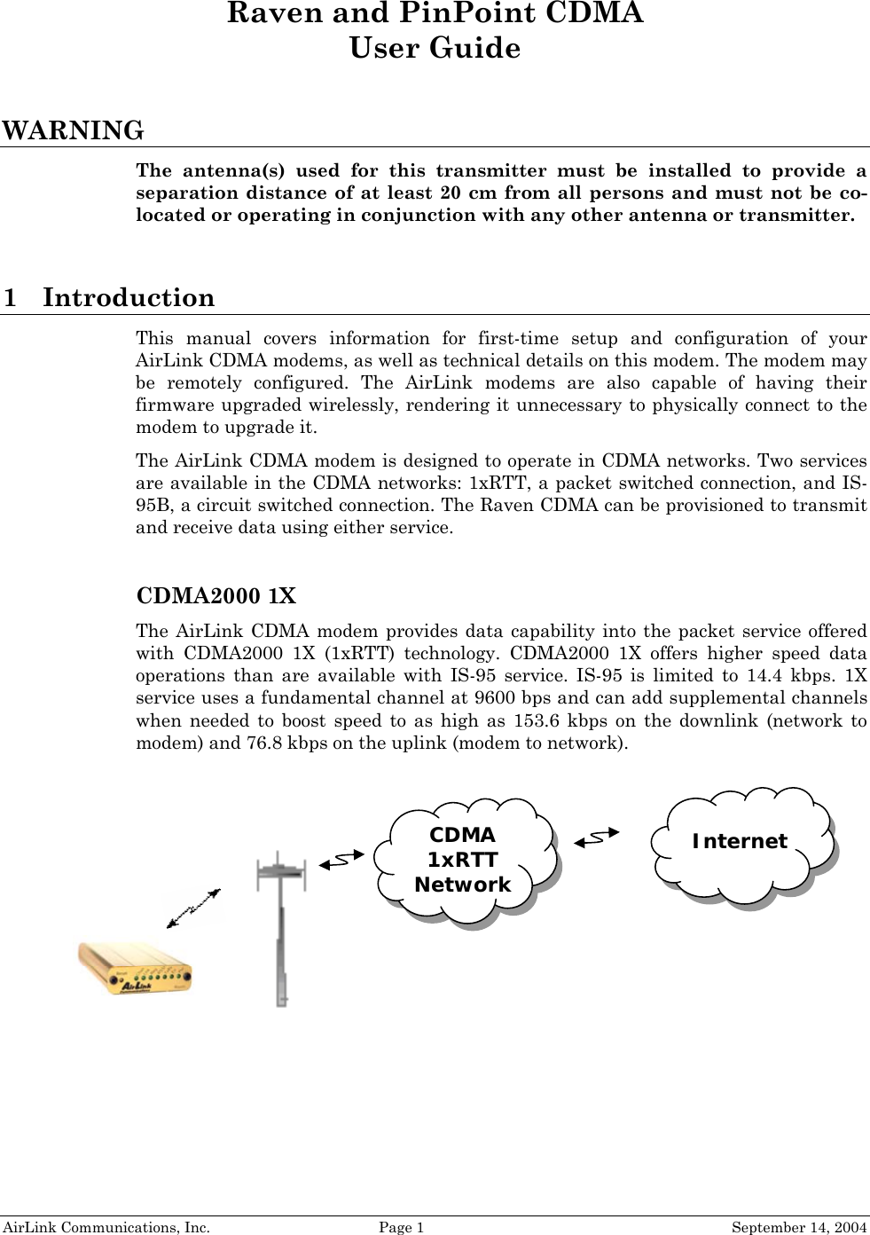
![Raven and PinPoint CDMA User Guide Version 1.21 AirLink Communications, Inc. Page 7 September 14, 2004 8. Type AT followed by [Enter]. You should receive an "OK" in response. 9. Type ATI1 followed by [Enter]. This displays the modem firmware version and you should also see "AirLink Communications, Inc." in it which ensures you are talking to the Raven CDMA modem. (If not, try changing COM ports.) Other AT commands may now be issued to the modem. See Section 5 for a list of AT commands 3.2 Modem Activation The Raven CDMA modem is usually already set up to register online with a phone number, etc. pre-configured into it (by AirLink Communications, Inc.). When a modem is registered on the network and working, the lights will look like the following: Note that the RSSI light may be flashing or solid, showing the strength of the signal. Also the Tx (transmit) and Rx (receive) lights will flash as data is transferred to and from the modem on the network. If your modem lights look like the above when the modem is powered on, you do NOT need to configure the phone number, etc. into the phone and may skip this section. ChanLinkRegTxRxRSSIErrResetRavenPwr](https://usermanual.wiki/Sierra-Wireless/Q2438.Raven-and-Pinpoint/User-Guide-468939-Page-15.png)
![Raven and PinPoint CDMA User Guide Version 1.21 AirLink Communications, Inc. Page 10 September 14, 2004 8. Enter 12345 (default password) and press [Enter]. You will receive an OK. Now you may enter any AT commands to the modem as you would if you were doing a local connection to the modem. See Section 5 for AT commands and their options. You may want to set local echo in your terminal emulator to see what you type as you type. There is no remote echo function in the modem.](https://usermanual.wiki/Sierra-Wireless/Q2438.Raven-and-Pinpoint/User-Guide-468939-Page-18.png)
![Raven and PinPoint CDMA User Guide Version 1.21 AirLink Communications, Inc. Page 25 September 14, 2004 5.1 IPManager and Dynamic DNS Updates The IPManager system provides a mechanism to implement a wireless Dynamic DNS service. If the IPManager settings are configured, the modem will send IP change notification messages to AirLink IPManager servers. These servers will then acknowledge the notifications and dynamically update a DNS server, thus allowing users to access a modem by domain name. The *IPMANAGER1 and *IPMANAGER2 settings can be set to either the domain name or IP address of a server to notify. The *MODEMNAME setting should be set to the name to prefix to the domain zone for which the IP Manager server is responsible. For example, if *MODEMNAME=mymodem and *IPMANAGER1 points to a server responsible for the eairlink.com domain zone, then the modem’s fully qualified domain name will be: mymodem.eairlink.com. To configure your AirLink modem to addressed by name, the modem needs to have 4 elements configured: 1. Modem name 2. Domain 3. IPManager IP Address 4. IPManager update interval The following illustrates a way to configure an AirLink modem to be addressed by name: at*modemname=mymodem at*domain=eairlink.com at*ipmanager1=eairlink.com at*ipmgrupdate1=60 [to update the DNS server at least hourly] 5.2 Using Names in the Modem, Domain Name Resolving The AirLink modems have an integrated DNS resolver, which uses the DNS entries specified by the *DNS1, *DNS2, and *DNSUSER settings. This allows the use of names in the AirLink modems instead of IP addresses. Both regular and reverse DNS lookups are supported. ATNSLOOKUP command will allow the lookup of an address or domain name. (e.g. atnslookup=www.microsoft.com will return the IP address for www.microsoft.com, while atnslookup=64.163.70.10 should return airlink.com). If a name resolution is performed on a name which is not fully qualified (i.e. contains no dotted portions), the value from *DOMAIN will be concatenated to the end. Typically the *DNS1 and *DNS2 values will be automatically filled in when a connection is negotiated with the carrier. The *DNSUSER value is provided to allow the user to specify a DNS server to check with before resorting to the carrier provided servers. If *DNSUSER is set to 0.0.0.0, it will be ignored and only the carrier DNS’s will be consulted. If it is set, the name server at the provided address will be queried first. If it doesn’t respond (within the timeout period, 10s) or can’t find the requested entry, the carrier DNS’s will then be queried. The special domain name “ppp-peer” will always resolve to the address to use to communicate with the PPP (or SLIP) host peer connected to the host port. If there is no PPP (or SLIP) peer (i.e. modem is not in PPP or SLIP mode), then “ppp-peer” will](https://usermanual.wiki/Sierra-Wireless/Q2438.Raven-and-Pinpoint/User-Guide-468939-Page-33.png)
![Raven and PinPoint CDMA User Guide Version 1.21 AirLink Communications, Inc. Page 28 September 14, 2004 6.1 AT Mode AT commands are used to configure the modem, command it to do something, or query a setting. AT commands must always be terminated by <CR> (ASCII character 0x0D). If E=1 (Echo On), the AT command (including the terminating <CR>) will be output before any responses defined in the next section. Response Framing Two settings affect the format of AT command output: V (Verbose) and Q (Quiet). If Q=1 (Quiet On), no result codes are output whatsoever, so there is no response generated by a (non query) command. If Q=0 (Quiet Off), result codes are output. The format of this output if then affected by the Verbose setting. If Quiet mode is off, the result code is affected as follows: For V=1 (Verbose mode), the textual result code is surrounded by <CR><LF> and any AT query response is also surrounded by <CR><LF>; for V=0, (Terse mode), a numeric result code is output with a single trailing <CR> (no <LF> is output), while any AT query response is followed by <CR><LF> (there is no preceding output). For example, possible output to the AT command “AT<CR>” (assuming quiet mode is not on) is: 0<CR> - if V=0 <CR><LF>OK<CR><LF> - if V=1 6.2 PPP Mode In PPP mode, the modem acts as a PPP server, providing an IP address, and DNS servers (if available) to the Host. PPP mode is entered from the AT mode by using any of the following commands: AT\APPP<CR> ATDT10.0.0.1<CR> ATDT10001<CR> ATD#19788<CR> CLIENT<CR> In response to any of the preceding commands, the modem will respond with CONNECT<CR><lf> and is ready for the host to begin PPP negotiations. The IP received by the host in the resulting negotiation will either be a private (non-routable) IP or a public (network-routable) IP provided by the network, depending on the settings of *USEPRIVATEIP [S300]. If *USEPRIVATEIP =1, the value of the private IP an be determined beforehand by querying S110. The private IP to be used can be defined with the command AT*PRIVATEIP=192.168.100.33 substituting the desired IP address.](https://usermanual.wiki/Sierra-Wireless/Q2438.Raven-and-Pinpoint/User-Guide-468939-Page-36.png)
![Raven and PinPoint CDMA User Guide Version 1.21 AirLink Communications, Inc. Page 29 September 14, 2004 Using a private IP insulates the PPP client from changes in IP addresses of the underlying network, as the AirLink modem will perform basic NAT-like address translation on all packets. If a public IP address is being used, any changes in the IP (as determined by the wireless network) will result in the PPP link to the host being disconnected, requiring the host to reinitiate it. The public IP is passed to the host in the PPP negotiations, so when the network forces a change, the modem has to force the host to renegotiate the PPP link to make this happen. The host can exit PPP mode by deactivating DTR (if S211=0 or &D2) or issuing the +++ escape sequence. Note that DTR needs to be asserted (or S211=1 or &D0) by the host before PPP mode can be entered. 6.3 PassThru Mode In PassThru mode, all serial traffic is sent directly between the internal OEM Module and the host. In this mode, the modem does not behave normally. This mode can be used to configure OEM Module-specific settings (e.g., for provisioning, etc.) Issuing the “AT\APASSTHRU” enters this mode. The modem responds with CONNECT, at which point a direct connection to the OEM Module is established. Note that some OEM Modules requires upwards of 20 seconds before AT commands can be entered, so be patient if there seems to be no response to AT commands. This mode can only be exited by resetting or power-cycling the modem. This mode cannot be entered via a telnet session. 6.4 UDP PAD Mode When the modem is in UDP PAD (Packet Assembly and Disassembly) Mode, all characters received on the serial port are assembled into UDP packets and sent to the mode’s remote IP address/port, and any packets received from the same IP/port-destined for the modem’s Device Port (see *DPORT)--are disassembled and dumped onto the serial line. Note that DTR needs to be asserted (or S211=1 or &D0) by the host before a UDP session can be entered. A UDP session is initiated by one of the following events: • Using the Dial UDP (DP) AT command (as in ATDP192.168.3.23/3456) • Setting the Startup Mode Default (MD) to 3 (UDP) so that a UDP session is entered automatically when the modem powers up. Serial data will be sent to the IP/port specified in S53. • An incoming UDP packet is received and - UDP auto answer is enabled (S82=2) - The destination IP address matches that in S53 - Or allow any IP is set (AIP=1) - The modem is in AT mode [not in a current UDP or TCP session]](https://usermanual.wiki/Sierra-Wireless/Q2438.Raven-and-Pinpoint/User-Guide-468939-Page-37.png)
![Raven and PinPoint CDMA User Guide Version 1.21 AirLink Communications, Inc. Page 30 September 14, 2004 UDP packet assembly is affected by the values of S50 (PAD Forwarding Timeout) and S51 (PAD Forwarding Character). Data received in the serial buffer will be transmitted when the idle inter-character timeout specified in S50 (in tenths of seconds) occurs or when a character is received that matches S51 (if non-zero). The host can exit UDP mode by deactivating DTR (if S211=0 or &D2) or by issuing the +++ escape sequence. 6.4.1 UDP Auto Answer UDP auto answer (previously called UDP half-open) is set with S82=2. When set, the modem will automatically establish a UDP session to the source IP address and port of the UDP packet received. The modem will remain “locked” to this one remote IP/port until no data is sent or received for the time interval defined in the UDP auto answer timeout (S83). During this session, packets from other IP/port addresses will be rejected, unless *UALL is set. Whether or not an incoming packet will cause the modem to enter a UDP session is always dependent on the S53 and AIP settings. When idle, after the timeout has occurred, the modem is in AT command mode on the serial port, and any valid AT command may be entered during this time. The Normal UDP Mode (MD3) can be combined with UDP auto answer to cause the incoming serial data to be sent in UDP packets (instead of being treated as AT commands), while allowing sessions to be established from different UDP sources. A UDP session will be initiated either by incoming serial data or by an incoming UDP packet. The session, started by either method, will be terminated when no data has been sent or received for the S82 period. Once the session terminates, another may be initiated by either means. When the session is initiated by serial data, the new session will be established using the destination address specified in S53. The S53 setting can be changed if the connect to last UDP setting (*UDPLAST=1) is set. The address in S53 will be updated to reflect the address of the last session initiated by an incoming UDP packet. So that when new data is received over the host serial port while in the idle state, a session will be re-established with the last address. (This behavior is the same as the previous Hybrid2 (MD6) mode). Note that TCP auto answer (S0=[1|2]) may also be set simultaneously with UDP auto answer. Then, when in the idle state, the modem will accept either a TCP or UDP incoming packet, and enter a TCP or UDP session as appropriate. 6.4.2 Reliable UDP Reliable UDP adds a simple protocol on top of UDP to provide reliable deliver of data. When data is received from the host serial port, a 2 byte header is added to the data, containing a message type and a sequence number. The modem will continue to send this data (buffering any received data in the meantime) until it receives an acknowledgement with this sequence number. If an acknowledgement is not received within the timeout period (specified in S7), the data will be retransmitted. This will continue until an acknowledgement is received or the modem is reset. Likewise any UDP packets received by the modem are expected to have this simple header. The modem will issue an acknowledgement for any valid packets which are received. Configure the modem as for a normal UDP session. Set the Startup Mode Default to 3, and the UDP Mode Default to 7 [ATMD73]. If using two modems, configure the Destination IP and Port in each to point to each other. Serial data will then be sent reliably between the two](https://usermanual.wiki/Sierra-Wireless/Q2438.Raven-and-Pinpoint/User-Guide-468939-Page-38.png)
![Raven and PinPoint CDMA User Guide Version 1.21 AirLink Communications, Inc. Page 31 September 14, 2004 Although it adds reliability, the simple implementation of the Reliable UDP mode in the modem does not check for duplicate packets. 6.4.3 Multicast UDP [Raven Only Feature] Multicast UDP results in any data received from the host serial port being sent to all the clients in the Modbus list. The remote port number is taken from S53. To avoid flooding the network, the packets are sent to each client with a 20ms pause in between. The receipt of UDP packets works as in normal UDP mode (i.e. bound by the value S53 and/or AIP). Since it may take a while to transmit the data to all hosts (especially if all 20 Modbus entries are used and name resolutions are required), new data received from the host port is buffered until current transmissions to all hosts are finished. Enter the list of target IPs in the Modbus IP list. The index numbers in the IP list aren't used. Configure the Raven as for a normal UDP session. Set the Startup Mode Default to 3, and the UDP Mode Default to 8 [ATMD83]. Configure the Destination port to match the device port of the remote modems. 6.5 TCP PAD Mode When the modem is in a TCP session, all characters received on the serial port are assembled into TCP packets and sent to the mode’s remote IP address/port, and any packets received from the remote end of the TCP connection are disassembled and dumped onto the serial line. Note that DTR needs to be asserted (or S211=1 or &D0) by the host before a TCP session can be entered. A TCP connection is established by one of the following methods: • Using the Dial TCP (DT) AT command (as in, ATDT192.168.3.23/3456) • TCP auto answer is enabled (S0=1|2), a TCP connection request is received, and the modem is not in a data session. • Data is received on the serial port and - The Startup Mode Default (MD) is 4 (auto TCP) - The remote TCP destination, as defined in S53, successfully responds to the TCP connection request. The value of S7 (TCP Connection Timeout) specifies the number of seconds to wait, after initiating a TCP connection attempt, for a successful connection to be established. If the connection has not been successfully established before the timeout occurs, ERROR/BUSY is returned. TCP packet assembly is affected by the values of S50 (PAD Forwarding Timeout) and S51 (PAD Forwarding Character). Data received in the serial buffer will be transmitted when the idle inter-character timeout specified in S50 (in tenths of seconds) occurs or when a character is received that matches S51 (if non-zero).](https://usermanual.wiki/Sierra-Wireless/Q2438.Raven-and-Pinpoint/User-Guide-468939-Page-39.png)
![Raven and PinPoint CDMA User Guide Version 1.21 AirLink Communications, Inc. Page 32 September 14, 2004 The TCP session will be terminated if no data is transmitted or received for the time interval specified in TCPT and TCPS. TCPT is the number of minutes [TCPS=0] or seconds [TCPS=1] used for this idle timeout. TCPT should never be 0 when using the TCP mode. A broken TCP session can result in the modem being left with a TCP half-open connection that can only be terminated with a reset. The host can also terminate a TCP session by deactivating DTR (if S211=0 or &D2) or issuing the +++ escape sequence. Note that DTR needs to be asserted (or S211=1 or &D0) by the host before a TCP session can be started. 6.6 TCP Auto Answer TCP auto answer (S0=1|2) also allows a TCP connection request to be “answered” when the modem is idle, not in a data session. Note that DTR needs to be asserted (or S211=1 or &D0) by the host before a TCP session can be entered. The TCP connection request’s destination port has to match the modem’s device port. Note that UDP auto answer may also be set simultaneously with TCP auto answer. Then, when in the idle state, the modem will accept either a TCP connection request or UDP incoming packet, and enter a TCP or UDP session as appropriate. 6.7 Hybrid Modes Some previous hybrid modes (MD=5, 6) are no longer implemented as special, unique modes. Now that UDP auto answer (UDP Half-open, S82=2) can be enabled in conjunction with UDP PAD mode (MD3), effectively this is the same as MD5 and MD6 previously accomplished. Setting MD5 and MD6 are still supported, but not recommended, since all they do is set several settings as described below. The settings to accomplish hybrid modes: AT Setting Hybrid (MD5) Hybrid2 (MD6) MD 3 3 S82 2 2 S0 1 1 *UDPLAST 0 1](https://usermanual.wiki/Sierra-Wireless/Q2438.Raven-and-Pinpoint/User-Guide-468939-Page-40.png)
![Raven and PinPoint CDMA User Guide Version 1.21 AirLink Communications, Inc. Page 33 September 14, 2004 6.8 SLIP Mode SLIP mode is entered be using the “AT\ASLIP” command. As in PPP Mode, the IP address that the host assumes is affected by the setting of S300. SLIP does not negotiate the IP with the host, so before making a SLIP connection, the host SLIP driver must be configured to use the IP specified by querying S110. The host can exit SLIP mode by deactivating DTR (if S211=0 or &D2) or issuing the +++ AT escape sequence. Note that DTR needs to be asserted (or S211=1 or &D0) by the host before SLIP mode can be entered. 6.9 Modbus/BSAP Configuration [Raven Only Feature] Modbus, BSAP, and Modbus variations are communications protocols that are widely used in telemetry. They were designed to be used in a radio environment where packets are broadcast to a group of remote units. Each Modbus packet contains an ID so that only the one remote unit, whose ID matches the ID in the packet, will respond to the host. The ID is used to address a specific remote. When Ravens are used in place of radios, there is a Raven connected to the host computer and a Raven connected to each remote unit. Packets transmitted from the host need to contain the IP address of the specific remote unit whose ID matches the ID in the packet from the host computer. The Modbus/BSAP feature adds the capability for a list of IP addresses or names, and matching remote IDs to be entered into the host Raven. When the host computer sends a poll request, the ID is matched to the corresponding IP address and a UDP packet is assembled using this IP address. The complete packet from the host is then encapsulated in this UDP packet and transmitted to the remote unit. The remote units operate in normal UDP mode and their data is sent to the host. 6.9.1 Configuring the Polling Host Application Raven Set the S53 Port to match whatever port number is being used on all the remote modems. For example, if the remote Ravens’ S110 port number being used is "12345", then the Modbus host Raven’s S53 port should be set to “12345”. ATMD13 for Modbus ASCII ATMD23 for Modbus RTU (Binary) ATMD33 for BSAP ATMD63 Variable Modbus [where you set up the individual parameters] Enter the list of ID/Local addresses and their associated remote IP addresses or names as follows: The ID/Local address and IP or name is entered using the ATMLIST or ATMLISTX commands. ATMLIST allows the ID to be entered in decimal, while ATMLISTX allows the ID to be entered in hex. For example, if a remote's IP address is 123.456.133.45 or name is remote1, and its ID/Local address is 27, you can enter: ATMLIST27=123.456.133.45](https://usermanual.wiki/Sierra-Wireless/Q2438.Raven-and-Pinpoint/User-Guide-468939-Page-41.png)
![Raven and PinPoint CDMA User Guide Version 1.21 AirLink Communications, Inc. Page 34 September 14, 2004 If you want to enter the ID is hex: ATMLISTX1B=123.456.133.45 Continue until all the remotes are entered. There can be a total of 20 remote ID/Local addresses entered into a Raven. Note a special build Raven Modbus Host version is available that allows up to 100 entries in the list. Remember to save the entries with AT&W. If Using Dynamic IPs The host Raven should be configured to report its current IP to a DDNS server so the remote Ravens can use DDNS to obtain the host Raven’s IP. The remote Ravens can then send their current IPs to the host Raven which will update the Modbus IP list by matching the modem names. Enter names into the IP list as follows: ATMLIST27=remote1 or ATMLISTX1B=remote1 Continue until all the remotes are entered. There can be a total of 20 remote ID/Local addresses entered into a Raven. Note a special build Raven Modbus Host version is available that allows up to 100 entries in the list. Remember to save the entries with AT&W. Configuring the Remote Ravens The remote Ravens connected to the RTUs being polled, need to be set up for normal UDP operation. ATMD3 for Normal UDP operation For Static IPs Set ATS53= IP address/port number of the Raven connected to the Polling Host. If the polling host Raven’s IP and port are 123.456.133.11 and 12345, set as follows: ATS53=123.456.133.11/12345 ATS53=home1/12345 If Using Dynamic IPs Set ATS53= name/port number of the host Raven. If the polling host Raven’s *MODEMNAME and Device Port are home1 and 12345, set as follows: ATS53=home1/12345 The remote Ravens need to be configured to update the host Raven with their current IPs. Set up *IPMANAGER[1|2] to point to the host Raven: *IPMANAGER[1|2]=home1 where home1 = *MODEMNAME in the host Raven. *DOMAIN should match the domain of the host Raven. For example, if the DDNS being used is eairlink.com, then *DOMAIN=eairlink.com. And the fully qualified domain name the remote Raven would query is home1.eairlink.com.](https://usermanual.wiki/Sierra-Wireless/Q2438.Raven-and-Pinpoint/User-Guide-468939-Page-42.png)
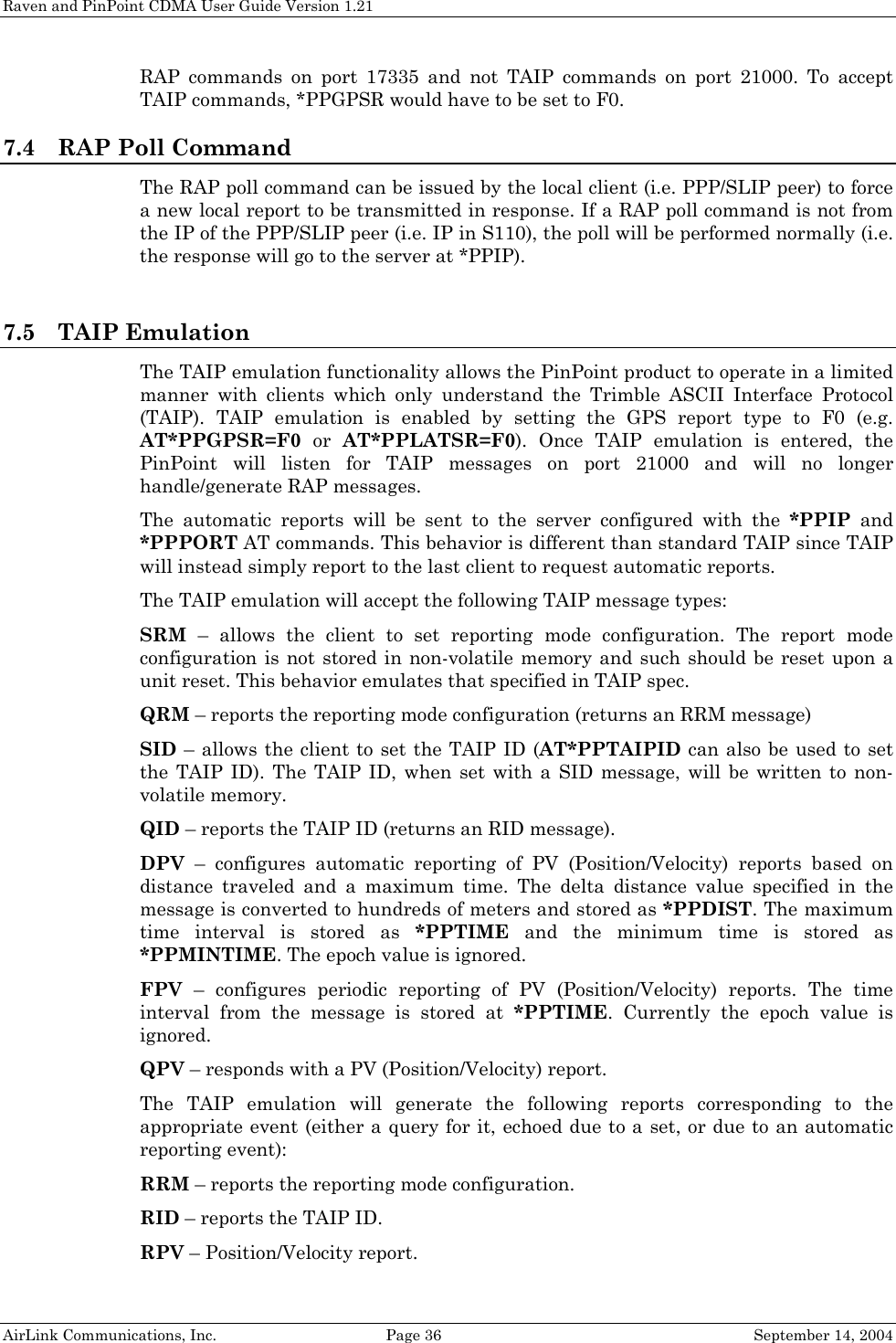
![Raven and PinPoint CDMA User Guide Version 1.21 AirLink Communications, Inc. Page 35 September 14, 2004 A new IP update will be sent anytime the remote Raven detects that its IP has changed. A periodic update is a redundant process that guarantees the host Raven will be updated in the event the host Raven loses its IP list for any reason or the remote Raven’s IP is changed or dropped without notification to the remote Raven. Configure the frequency the IP update will be occur. AT*IPMGRUPDATE[1|2]=n where n = minutes [0-255] Other parameters may need to be changed, but this is dependent on the RTU type being used. Remember to save your configuration with AT&W. 7 PinPoint Notes 7.1 Low-power Mode A PinPoint can be configured to enter a low power mode in order to conserve a vehicle’s battery life. The PinPoint can power down when the voltage to the modem drops below a configured threshold (caused by the vehicle being turned off), or when DTR changes (usually a contact or voltage controlled by the key switch, signaling when the vehicle is turned off). Important: the external DB9’s RTS and DTR pins can be configured through ATS to be used as digital inputs. If one or both pins have been configured to be used as inputs, then low power mode cannot be keyed off of DTR. 7.1.1 Effect on Modem State Once the transition from powered on to low-power mode starts, the modem will change state to AT mode. This results in the current mode (e.g. PPP, TCP, etc.) being gracefully terminated. For the brief period when the modem is preparing for low-power mode, the modem will remain in AT mode (i.e. won’t auto-answer, ATD will fail, etc.). Once low-power mode is entered, the modem will then discard any data received on the host port. When the modem is woken from low-power mode, the same behavior occurs as upon power on. The modem starts in AT mode, and then after 5 seconds will enter the default mode (MD). 7.2 Real-Time Clock Sync Every hour, the modem will re-sync the internal RTC with the UTC time received from the GPS satellites; 7.3 Different Local and Remote Report types A different report type can be specified for local reports (*PPLATSR) than that for remote reports (*PPGPSR). The type of commands (either RAP or TAIP) which the PinPoint accepts and the port it listens on depends on the value for *PPGPSR. For example if *PPGPSR is set to send RAP GPS reports w/date (AT*PPGPSR=12) and *PPLATSR is set to send TAIP reports (AT*PPLATSR=F0), the PinPoint will accept](https://usermanual.wiki/Sierra-Wireless/Q2438.Raven-and-Pinpoint/User-Guide-468939-Page-43.png)

![Raven and PinPoint CDMA User Guide Version 1.21 AirLink Communications, Inc. Page 38 September 14, 2004 8 PinPoint Specific AT Commands These AT commands are specific to the AirLink PinPoint. Command Description DTRP=n [?] x3310, x3311 Set or query the DTR power control. n = 0: Ignore DTR for power control n = 1: Enter low power mode when DTR is low n = 2: Enter low power mode when DTR is high NOTE: Also see PTMR GPSn x3310, x3311 Send NMEA GPS strings out serial link. ATGPS will cause the NMEA GGA, RMC, and VTG GPS strings to output to the serial port one time. ATGPS1 will cause these strings to be sent out the serial link once per second continuously until ATGPS or until reset See *PGPS PTMR=n [?] x3310, x3311 Number of minutes after one of the power down events (VTLG or DTRP) happens until the PinPoint enters the low power mode. n = 0-255. If DTRP and VLTG are both 0 (zero), this setting does nothing. NOTE 1: There is always a minimum of 1 minute between power down event and actual shutdown (to give the modem time to prepare); entering zero will not power down the modem immediately, but after one minute. NOTE 2: In the first 5 minutes after modem powers up, power down events are ignored to give the user time to change configurations. VLTG=n [?] x3310, x3311 Set or query the voltage level at which the PinPoint goes into low power mode. n = 0: Ignore voltage for power control n = low power voltage threshold in tenths of volts. Example: ATVLTG=130 would power down the modem if the voltage goes below 13.0V. *DTRI=n x3310, x3311 Enable monitoring the DTR signal as in input event. n = 0: Disable DTR input monitoring n = 1: Enable DTR input monitoring NOTE: If DTR is used as an input, DTR cannot be used for low-power control. (See DTRP)](https://usermanual.wiki/Sierra-Wireless/Q2438.Raven-and-Pinpoint/User-Guide-468939-Page-46.png)
![Raven and PinPoint CDMA User Guide Version 1.21 AirLink Communications, Inc. Page 39 September 14, 2004 Command Description *MF=hh [?] x3310, x3311 Set or query GPS format, where hh is a hex value; 8E (transmit Lat/Long/Dir/Vel/Time in binary) or 8F. *PGPS=n [?] x3310, x3311 Send NMEA GPS strings out serial link [n=1]. Similar to ATGPS except that the *PGPS value can be saved to NVRAM so that it will continue to operate after resets. *POWERMODE? x3310, x3311 Displays the current power state/mode. Possible values returned are: INITIAL – the modem is in the initial 5 minutes since power up, so power down event will be ignored. ON – regular power on, i.e. a power down is not pending. LOW CANCELLABLE – power down is pending but still cancelable if the power down trigger goes away. LOW PENDING 1 and 2 – power down is pending, any modem tasks are gracefully preparing for the power down. LOW FINAL – power down is imminent. LOW – power is down. *PPDEVID=0|1 [?] x3310, x3311 Whether or not the PinPoint should include the 64-bit device ID in its GPS reports. Valid values are 0 or 1. NOTE: This setting MUST be 1 if the modem uses a Dynamic IP-based wireless technology (e.g., CDMA or GPRS) *PPDIST=n [?] x3310, x3311 GPS Report Distance Interval in 100 Meter Units Range n = 1-65535, 0 = Disabled *PPGPSR=n [?] x3310, x3311 GPS report type. n= 0x11 – Standard GPS Report n= 0x12 – Standard GPS Report + UTC Date n= 0x13 – Standard GPS Report + UTC Date + RF data n=0xE0 – GGA and VTG NMEA reports n=0xE1 – GGA, VTG and RMC NMEA reports n=0xF0 – TAIP reports *PPIGNOREIP=[0,1] [?] x3310, x3311 When enabled, ignore PinPoint Server IP (*PPIP) updates in RAP. 0 = Enabled. 1 = Disabled. *PPIP=ipAddr [?] x3310, x3311 PinPoint Server IP Address = IP address where GPS reports are sent. Example: AT*PPIP=192.100.100.100 NOTE: Also see *PPPORT](https://usermanual.wiki/Sierra-Wireless/Q2438.Raven-and-Pinpoint/User-Guide-468939-Page-47.png)
![Raven and PinPoint CDMA User Guide Version 1.21 AirLink Communications, Inc. Page 40 September 14, 2004 Command Description *PPLATS=n [?] x3310, x3311 Local ATS – Causes GPS reports to also be sent out the serial link every n seconds [n=0..255], when there is a PPP connection to the serial host established. n = 0 disables this feature NOTE: Sends to the PPP peer IP [S110] with the Destination Port number [S53]. *PPLATSR=n [?] x3310, x3311 Indicates the type of GPS report to send to the local client (PPP/SLIP peer). This value can be set to any of the valid GPS report types (see *PPGPSR). *PPMINTIME=n [?] x3310, x3311 Specifies the minimum amount of time between reports generated due to either the time interval (*PPTIME) or the distance interval (*PPDIST). This is useful to limit network traffic and make more efficient use of bandwidth. This can be used in conjunction with store and forward. n = number of seconds [0-65535] to wait between sending time or distance triggered reports. The minimum value which this setting can take depends on the policies of the carrier. 0 = Disabled. *PPODOM=0|1[?] x3310, x3311 Enable odometer reporting n = 0 - Odometer reporting is disabled [default] n = 1 - Odometer reporting is enabled *PPODOMVAL=n [?] x3310, x3311 Set or query the PinPoint’s current odometer value. The value is in meters. Maximum value is approximately 4.3 billion meters (2.5 million miles). *PPPORT=n [?] x3310, x3311 Port where GPS reports are sent. Possible value: nnnnn = 1 – 65535 NOTE: Also see ATSIP. *PPSNF=n [?] x3310, x3311 Set or query the GPS report Store and Forward feature. Store and Forward will cause GPS reports to be stored up if the PinPoint goes out of network coverage. Once the vehicle is in coverage the GPS reports will be sent en masse to the server. n = 0: Disable Store and Forward n = 1: Enable Store and Forward (default)](https://usermanual.wiki/Sierra-Wireless/Q2438.Raven-and-Pinpoint/User-Guide-468939-Page-48.png)
![Raven and PinPoint CDMA User Guide Version 1.21 AirLink Communications, Inc. Page 41 September 14, 2004 Command Description *PPSNFB=n [?] x3310, x3311 Store and Forward Behavior. When *PPSNF=1, the type of Store and Forward behavior is defined by: n = 0: Normal Store and Forward. Data is stored when the PinPoint is out of CDPD coverage; when the PinPoint is in coverage, data is sent to server as soon as possible. This is the default for PinPoints with RAP version 1.3 or lower. n = 1: Data sent only when polled. Data is stored until polled using the Poll command sent by a server. n = 2: Grouped Reports. Data is stored until the desired minimum number of reports (see *PPSNFM) has been stored. The data is then sent to the server in groups with at least the specified number of reports. *PPSNFM=n [?] x3310, x3311 Store and Forward Minimum Reports. n = 0 to 255 n specifies the minimum number of reports that must be stored before they are forwarded to the server. The data is then sent to the server in packets that contain at least this number of reports. *PPSNFR=n [?] x3310, x3311 Store and Forward Reliability GPS reports will be retransmitted if not acknowledged by the server. n = 0: SnF reliability is disabled n = 1: SnF reliability is enabled *PPTAIPID=xxx [?] x3310, x3311 Sets/queries the TAIP ID. This ID is returned in TAIP reports if it has been negotiated with the TAIP client. This value is only used in conjunction with TAIP emulation mode (*PPGPSR=F0). xxxx = the 4 character TAIP ID to assign this device. *PPTIME=n [?] x3310, x3311 GPS Report Time Interval Range n = 1 – 65535 Seconds, 0 = Disabled NOTE: A report time of less than 30 seconds in a CDMA network, can possibly keep an RF link up continuously. This will eventually cause the PinPoint to overheat and shutdown, plus annoy the CDMA carrier since an RF resource will be tied up to transfer small amounts of data. The CDMA RF channel will be released and go dormant in 10-20 seconds of no data sent or received. NOTE: Some carriers may impose a minimum transmit time. See *PPMINTIME NOTE: Also see *PPTSV NOTE: Also see +CTA [for CDMA}](https://usermanual.wiki/Sierra-Wireless/Q2438.Raven-and-Pinpoint/User-Guide-468939-Page-49.png)
![Raven and PinPoint CDMA User Guide Version 1.21 AirLink Communications, Inc. Page 42 September 14, 2004 Command Description *PPTSV=n [?] x3310, x3311 Timer for Stationary Vehicles. n = [0--255]: Time interval in minutes that the PinPoint will send in reports when it is stationary. For example, if *PPTIME=10, the PinPoint will send in reports at least every 10 seconds while it is moving; however, once it stops moving, it will slow the reports down to this *PPTSV value. A zero value disables the stationary vehicle timing. *RTSI=n x3310, x3311 Enable monitoring the RTS signal as in input event. n = 0: Disable RTS input monitoring n = 1: Enable RST input monitoring NOTE: If RTS is used as an input, hardware flow control cannot be enabled *UDPRGPS=n [?] x3310, x3311 Set or query GPS stamping of UDP Reliable packets. When set, data received on the host serial port will be encapsulated with the GPS date and time. n = 0: Disable GPS stamping (default) n = 1: Enable GPS stamping #IG=n [?] x3310, x3311 Set or query GPS initialization timer. n = seconds. Time in seconds to wait for GPS acquisition before transmitting at high rates. #U x3310, x3311 Immediately issue GPS report to the PinPoint server IP and port](https://usermanual.wiki/Sierra-Wireless/Q2438.Raven-and-Pinpoint/User-Guide-468939-Page-50.png)
![Raven and PinPoint CDMA User Guide Version 1.21 AirLink Communications, Inc. Page 43 September 14, 2004 9 Raven Specific AT Commands These commands are specific to the Raven. Command Description IPL=n [?] x3210, x3211 IP List Dial This allows access the Modbus IP list using the first two digits of the dial string. Example: ATDT1234567 would go to ID “12” on the Modbus list and used the associated IP as the destination. n = 0: Disabled n = 1: Enabled MLISTid=d.d.d.d [?] x210, x3211 Enters an ID and IP address into the Modbus List id is a decimal value MLISTX hexed=d.d.d.d [?] x3210, x3211 Enters an ID and IP address into the Modbus List hexid is a hexadecimal value MVLEN=n [?] x3210, x3211 Modbus Variant ID Length Length of the RTU ID in a modbus-variant protocol, in bytes. This parameter is used to define the length of the RTU ID in Modbus-like protocol data packets. This parameter is used when the when the Mode Default (MD) is set to hex 63. n = 1 or 2 MVOPT=n [?] x3210, x3211 Modbus Variant Option Sets various behavioral options when dealing with a Modbus-variant protocol. This parameter is used when the when the Mode Default (MD) is set to hex 63 n = 0: No special action (Default) n = 1: Skip leading zeroes in Modbus packets. MVMSK=hh [?] x3210, x3211 Modbus Variant ID Mask Byte hex mask to use when extracting the ID. Specify which bits in the ID field to use. This parameter is used when the when the Mode Default (MD) is set to hex 63 hh = 00-FF hex value hh = 00 [default] no mask, use all 8 bits hh = 0F use only the low order 4 bits MVTYP=n [?] x3210, x3211 Modbus Variant Type The data-type of the RTU ID in a modbus-variant protocol. This parameter is used to define the data-type of the RTU ID in Modbus-like protocol data packets. This parameter is used when the Mode Default (MD) is set to 63. n = 0: Binary (Default) n = 1: ASCII Hex n = 2: ASCII Decimal](https://usermanual.wiki/Sierra-Wireless/Q2438.Raven-and-Pinpoint/User-Guide-468939-Page-51.png)
![Raven and PinPoint CDMA User Guide Version 1.21 AirLink Communications, Inc. Page 44 September 14, 2004 Command Description RKEY=n [?] x3210, x3211 Radio Transceiver Keying - n = 0: Off (Default) n = 1; On Enable/disable MDS Radio transceiver keying. Radio keying is designed to assert CTS when a packet is received, delay the time as specified, send the data out the serial port, wait the same amount time, drop CTS. This way, the CTS signal can be used to key a transmitter on and give it time to reach its power level before data is sent to it. Delay interval is specified in S221.](https://usermanual.wiki/Sierra-Wireless/Q2438.Raven-and-Pinpoint/User-Guide-468939-Page-52.png)
![Raven and PinPoint CDMA User Guide Version 1.21 AirLink Communications, Inc. Page 46 September 14, 2004 Command Description AIP=n [?] n = 0: Allow only the IP specified in S53 to connect when UDP auto answer is enabled (S82=2). n = 1: Allow any incoming IP to connect when UDP auto answer is enabled (S82=2). Always subject to any Friends filters that may be defined D[method][d.d.d.d][/ppppp] or D[method][[@]name][/ppppp] Dial a connection to a remote IP and Port using either UDP, TCP, or Telnet. method = P – Establish a UDP connection T – Establish a TCP connection N – Establish a Telnet connection d.d.d.d = IP address to establish connection to name = domain name to establish connection to ppppp = IP port to establish connection to Examples: ATD – Dial (establish) default connection per S53 ATDPnnn.nnn.nnn.nnn[/ppppp] - Dial (establish) UDP session to the specified IP address/port. If the method, IP address, or port is omitted, the values from S53 are used. If a telnet connection is requested (N) and the port is not supplied, port 23 will be used instead of the value from S53. Several special dialing numbers exist to make it easy to establish a PPP or SLIP connection with the modem. ATD#19788 or ATDT#19788 will establish a PPP connection (see \APPP) and ATDT#7547 will establish a SLIP connection (see \ASLIP). If a domain name is specified, the ‘@’ symbol can be used to explicitly indicate the start of the name. For example, if “ATDPHONY” is issued, this will be interpreted as dial a UDP connection to ”HONY”. To dial using the default method to host “PHONY”, one would issue “ATD@PHONY”. To end the connection, issue the +++ escape sequence or drop the DTR line (if Ignore DTR S211=0 or &D2) NOTE: The source port of the session is the Device Port (set by S110 or *DPORT) DAE=n [?] Disable AT Escape Sequence detection n = 0: Enable +++ AT escape sequence detection. n = 1: Disable +++ AT escape sequence detection. DTRP=n [?] x3310, x3311 Set or query the DTR power control. n = 0: Ignore DTR for power control n = 1: Enter low power mode when DTR is low n = 2: Enter low power mode when DTR is high NOTE: Also see PTMR](https://usermanual.wiki/Sierra-Wireless/Q2438.Raven-and-Pinpoint/User-Guide-468939-Page-54.png)
![Raven and PinPoint CDMA User Guide Version 1.21 AirLink Communications, Inc. Page 47 September 14, 2004 Command Description En Toggle AT command echo mode. n = 0: Echo Off n = 1: Echo On. FM=n [?] Friends Mode – Only allow specified IPs to access the modem n = 0: Disable Friends mode n = 1: Enable Friends mode – Only packets from friends will be accepted (see below); packets from other IP addresses are ignored. Fn=d.d.d.d [?] Friends mode IP address n = Friends list index [1 – 10] d.d.d.d = IP address to be allowed to access the modem 255 = allow any number 0-255 Example: 166.129.2.255 allows access by all IPs in the range 166.129.2.0—166.129.2.255. GPSn x3310, x3311 Send NMEA GPS strings out serial link. ATGPS will cause the NMEA GGA, RMC, and VTG GPS strings to output to the serial port one time. ATGPS1 will cause these strings to be sent out the serial link once per second continuously until ATGPS or until reset See *PGPS H This command does nothing but does not cause an error either. HOR=n [?] Half-Open Response – In UDP auto answer (half-open) mode: n = 0: No response codes when UDP session is initiated n = 1: RING CONNECT response codes sent out serial link before the data from the first UDP packet. Note: Quiet Mode must be Off. I[0] Returns the product name. I1 Returns AirLink modem’s firmware version, hardware ID, and copyright. I2 Returns the OEM Modem’s firmware version and relevant hardware ID I3 Returns the OEM Modem’s unique ID IPL=n [?] x3210, x3211 IP List Dial This allows access the Modbus IP list using the first two digits of the dial string. Example: ATDT1234567 would go to ID “12” on the Modbus list and used the associated IP as the destination. n = 0: Disabled n = 1: Enabled M This command does nothing but does not cause an error either.](https://usermanual.wiki/Sierra-Wireless/Q2438.Raven-and-Pinpoint/User-Guide-468939-Page-55.png)
![Raven and PinPoint CDMA User Guide Version 1.21 AirLink Communications, Inc. Page 48 September 14, 2004 Command Description MDhh [?] Set or query the modem's default power-up mode hh (hex byte) = When the modem is power-cycled, it may enter the mode specified by this command after 5 seconds. On startup, typing ATMD0 within 5 seconds changes the mode to normal. 00 – normal (AT command) mode 01 – SLIP mode 02 – PPP mode 03 – UDP mode (address/port is in S53) 04 – TCP mode (address/port is in S53) [Also see Modbus Modes for Ravens] MLISTid=d.d.d.d [?] x3210, x3211 Enters an ID and IP address into the Modbus List id is a decimal value MLISTX hexed=d.d.d.d [?] X3210, x3211 Enters an ID and IP address into the Modbus List hexid is a hexadecimal value MVLEN=n [?] x3210, x3211 Modbus Variant ID Length Length of the RTU ID in a modbus-variant protocol, in bytes. This parameter is used to define the length of the RTU ID in Modbus-like protocol data packets. This parameter is used when the when the Mode Default (MD) is set to hex 63. n = 1 or 2 MVOPT=n [?] x3210, x3211 Modbus Variant Option Sets various behavioral options when dealing with a Modbus-variant protocol. This parameter is used when the when the Mode Default (MD) is set to hex 63 n = 0: No special action (Default) n = 1: Skip leading zeroes in Modbus packets. MVMSK=hh [?] x3210, x3211 Modbus Variant ID Mask Byte hex mask to use when extracting the ID. Specify which bits in the ID field to use. This parameter is used when the when the Mode Default (MD) is set to hex 63 hh = 00-FF hex value hh = 00 [default] no mask, use all 8 bits hh = 0F use only the low order 4 bits MVTYP=n [?] x3210, x3211 Modbus Variant Type The data-type of the RTU ID in a modbus-variant protocol. This parameter is used to define the data-type of the RTU ID in Modbus-like protocol data packets. This parameter is used when the Mode Default (MD) is set to 63. n = 0: Binary (Default) n = 1: ASCII Hex n = 2: ASCII Decimal](https://usermanual.wiki/Sierra-Wireless/Q2438.Raven-and-Pinpoint/User-Guide-468939-Page-56.png)
![Raven and PinPoint CDMA User Guide Version 1.21 AirLink Communications, Inc. Page 49 September 14, 2004 Command Description OPRG=n [?] Enables/disables over-the-air firmware upgrading of the modem. n = 0: Disables over-the-air programming. n = 1: Enables over-the-air programming. PINGd.d.d.d[,n] PING domain_name[,n] Ping the specified IP address. Sends a single ping, returns either OK or ERROR depending on result. Times out in 10 seconds. If n is provided, it specifies the amount of data to send with the ping. If n is not provided, the default, 50 bytes is used. PTMR=n [?] x3310, x3311 Number of minutes after one of the power down events (VTLG or DTRP) happens until the PinPoint enters the low power mode. n = 0-255. If DTRP and VLTG are both 0 (zero), this setting does nothing. NOTE 1: There is always a minimum of 1 minute between power down event and actual shutdown (to give the modem time to prepare); entering zero will not power down the modem immediately, but after one minute. NOTE 2: In the first 5 minutes after modem powers up, power down events are ignored to give the user time to change configurations. Qn [?] Set or query the AT quiet-mode setting. If quiet mode is set, there will be no responses to AT commands except for data queried. n = 0: Off (Default) n = 1: Quiet-mode on. RKEY=n [?] x3210, x3211 Radio Transceiver Keying - n = 0: Off (Default) n = 1; On Enable/disable MDS Radio transceiver keying. Radio keying is designed to assert CTS when a packet is received, delay the time as specified, send the data out the serial port, wait the same amount time, drop CTS. This way, the CTS signal can be used to key a transmitter on and give it time to reach its power level before data is sent to it. Delay interval is specified in S221. S0=n [?] This register determines how a modem responds to an incoming TCP connection request. The modem remains in AT Command mode until a connection request is received. DTR must be asserted or (or S211=1 or &D0) must be set for a successful TCP connection. The modem will send a “RING” string to the host. A “CONNECT” sent to the host indicates acknowledgement of the connection request and the TCP session is established. n = 0: Off (Default) n = 1: On n = 2: Use Telnet server mode on TCP connections S7=n [?] Specifies the number of seconds to wait for a TCP connection to be established when dialing out.](https://usermanual.wiki/Sierra-Wireless/Q2438.Raven-and-Pinpoint/User-Guide-468939-Page-57.png)
![Raven and PinPoint CDMA User Guide Version 1.21 AirLink Communications, Inc. Page 50 September 14, 2004 Command Description S23=<speed>,<databits> <parity><stop bits> [?] Query or set serial line parameters: <speed> = [1200 | 2400 | 4800 | 9600 | 19200 | 38400 | 57600 | 115200 | 230400] <databits> = [7 | 8] <parity> = [O=Odd| E=Even | N=None | M=Mark] <stopbits> = [1|1.5|2] Example: ATS23=19200,8N1 (sets modem to 19200, etc.) The settings take affect after reset. NOTE: MUST be 8 data bits for PPP mode. S50=n [?] Set or query data forwarding idle timeout. n = tenths of seconds. (Used in UDP or TCP PAD mode) S51=n [?] Set or query PAD data forwarding character. n = 0: no forwarding character n = other: ASCII code of character that causes data to be forwarded. (Used in UDP or TCP PAD mode.) S53= [method]d.d.d.d[/ppppp] [?] Set or query Destination IP address, port, and method. These are used as defaults for the D (Dial) AT command. method = P – UDP T – TCP N – Telnet d.d.d.d = IP address ppppp = the port address ATS53=T192.168.100.23/12345 ATS53=192.168.100.23/12345 ATS53=/12345 S60=n [?] Telnet Client Echo Mode n = 0: No Echo n = 1: Local Echo (Default) n = 2: Remote Echo S82=n [?] Enables UDP auto answer (half-open) mode. n = 0: Normal mode n = 2: Enable UDP auto answer mode. S83=n [?] Set or query UDP auto answer idle timeout. If no data is sent or received before the timeout occurs, the current UDP session will be terminated. While a session is active, packets from other IPs will be discarded (unless *UALL is set). n = 0: No idle timeout (Default). n = 1-255: Timeout in seconds.](https://usermanual.wiki/Sierra-Wireless/Q2438.Raven-and-Pinpoint/User-Guide-468939-Page-58.png)
![Raven and PinPoint CDMA User Guide Version 1.21 AirLink Communications, Inc. Page 51 September 14, 2004 Command Description S110=d.d.d.d[/ppppp] [?] Used to query or set IP address and port for CDPD modems, or only sets the modem’s Device Port for CDMA and GPRS modems. Since the IP address is determined from the CDMA and GPRS networks, any specified address will be ignored. If S300=0 you will get the network IP when you query this value. If S300=1 you will get the private IP address. d.d.d.d = IP address ppppp = port number NOTE: See also S300,*DPORT S202? Queries the current RSSI in dBm S211=n [?] Ignore DTR. For applications or situations where hardware control of the DTR signal is not possible, the modem can be configured to ignore DTR. When Ignore DTR is enabled, the modem operates as if the DTR signal is always asserted. n=0 [default]: Use hardware DTR. [&D2] n=1: Ignore DTR. [&D0] n=3: Ignore DTR and assert DSR. This value is deprecated, and it is recommended to use &S to control the DSR instead. When this value is set to 3, &S will automatically be set to 0. S221=n [?] Connect Delay [n = 0 - 255] n = number of seconds to delay the “CONNECT’ response upon establishing a TCP connection OR n = number of tenths of seconds to delay before outputting ENQ on the serial port after the CONNECT when the ENQ feature is enabled [see *ENQ] TCPS=n [?] TCP connection timeout (TCPT) units. n = 0: TCPT specifies minutes. n = 1: TCPT specifies seconds. TCPT=n [?] TCP connection timeout. Specifies a time interval upon which if there is no in or outbound traffic through a TCP connection, the connection will be terminated. This value only affects the TCP connection in TCP PAD mode. n = minutes (if TCPS=0) or seconds (if TCPS=1) Vn [?] Set or query Command Response Mode. n = 0: Terse (numeric) command responses n = 1: Verbose command responses (Default).](https://usermanual.wiki/Sierra-Wireless/Q2438.Raven-and-Pinpoint/User-Guide-468939-Page-59.png)
![Raven and PinPoint CDMA User Guide Version 1.21 AirLink Communications, Inc. Page 52 September 14, 2004 Command Description VLTG=n [?] x3310, x3311 Set or query the voltage level at which the PinPoint goes into low power mode. n = 0: Ignore voltage for power control n = low power voltage threshold in tenths of volts. Example: ATVLTG=130 would power down the modem if the voltage goes below 13.0V. Xn [?] Extended Call Progress Result mode. n = 0: turn off extended result codes (Default) n = 1: turn on result codes. This adds the text 19200 to the CONNECT response. Z Reset the modem. NOTE: This command does nothing if *DATZ=1. #IG=n [?] x3310, x3311 Set or query GPS initialization timer. n = seconds. Time in seconds to wait for GPS acquisition before transmitting at high rates. #U x3310, x3311 Immediately issue GPS report to the PinPoint server IP and port &Cn [?] Set DCD mode. n = 0: Always assert DCD n = 1: Assert DCD when in a data mode (UDP, TCP, PPP, or SLIP) (Default). n = 2: Assert DCD when the modem has network coverage. &Dn [?] Set DTR mode. n = 0: Ignore DTR, same effect as HW DTR always asserted (same as S211=1) n = 2: Use hardware DTR (same as S211=0) &L<speed>,<databits> <parity><stop bits> Set serial line parameters (see S23) &Sn [?] Set DSR mode. n = 0: Always assert DSR n = 1: Assert DSR when in a data mode (UDP, TCP, PPP, or SLIP) (Default). n = 2: Assert DSR when the modem has network coverage. Note: Although deprecated, S211 can also be used to request that DSR is always asserted. If S211 is set to 3 and &S is changed to a non-zero value, S211 will be changed to 1. &V View active profile (the contents of the registers) &W Writes all changed modem settings. If this command is not issued, any modified values will revert back to their previous values at modem reset. &Z This command does nothing but does not cause an error either.](https://usermanual.wiki/Sierra-Wireless/Q2438.Raven-and-Pinpoint/User-Guide-468939-Page-60.png)
![Raven and PinPoint CDMA User Guide Version 1.21 AirLink Communications, Inc. Page 53 September 14, 2004 Command Description \ACEPW=new123 Change the Ace password to a new value. Password is case sensitive. Default value is 12345 Example: AT\ACEPW=new123 \APASSTHRU Set modem operation to pass through mode. This will pass any characters received on the serial port directly to the internal OEM Modem and output any characters from the internal OEM Modem out the serial port. This allows direct access/configuration of the OEM Modem. Once this mode is entered, the unit must be physically reset to return to normal operation. NOTE: It may take up to 30 seconds for the OEM Modem to respond after CONNECT is output. NOTE: This mode is not available through the remote AT telnet server. \APPP Set modem operation to PPP mode. The modem expects the Host to start PPP negotiation. DTR must be asserted or (&D0 or S211=1) \ASLIP Set modem operation to SLIP mode. DTR must be asserted or (&D0 or S211=1) \Qn [?] Set or query the serial port flow control setting. n = 0: No flow control is being used n = 2: RTS/CTS hardware flow control is being used n = 4: Transparent software flow control. Uses escaped XON and XOFF for flow control. XON and XOFF characters in data stream are escaped with the @ character (0x40). @ in data is sent as @@. *CSX1=[0|1] [?] If set (*CSX=1), PASSTHRU mode will echo all host received data and will not pass the data to the modem while the modem is not asserting DCD. If the modem is asserting DCD, data will be passed from the host to the modem as it normally is when *CSX1=0. *CTSE=n [?] Clear To Send Enable This feature asserts CTS when there is a network connection. Note: Flow control (AT\Q) will override this indication, so if you want to use CTS to indicate network coverage, flow control has to be off (AT\Q0). RS232 voltage levels: Positive = Network coverage, Negative = no coverage. n = 0: Disabled (Default). n = 1: Enable assertion of CTS when there is network coverage. *DATE=[mm/dd/yyyy],[hh:mm:ss] [?] Sets and queries the clock in the unit. Either the date and time can be specified, or simply one of the two can be specified in which case the unspecified value will remain unchanged. The date and time are always specified in UTC (Universally Coordinated Time) and, as such, the hours are specified in 24-hours format. Note that if the product has a GPS (i.e. PinPoints), the GPS will be used to set the time, in which case any date/time specified will be ignored.](https://usermanual.wiki/Sierra-Wireless/Q2438.Raven-and-Pinpoint/User-Guide-468939-Page-61.png)
![Raven and PinPoint CDMA User Guide Version 1.21 AirLink Communications, Inc. Page 54 September 14, 2004 Command Description *DATZ=n [?] Enables or disables reset on ATZ n = 0: Normal Reset (Default). n = 1: Disable Reset on ATZ. *DBGIPLVL=n [?] Sets the logging level for the IP subsystem. n = 0: No logging n = 1: Log errors (i.e. invalid/corrupt packets, etc.). n = 2: Log the header of all received packets. Note that this can quickly exhaust the event log. *DBGPPPLVL=n [?] Sets the logging level for the PPP stack. n = 0: No logging n = 1-3: Enables logging at different levels of detail. *DEVICEID=n [?] Sets or queries the 64-bit Device ID that is used by the modem to identify itself to the server. The default is a value that depends on the underlying communications technology being used. *DEVICEIDX=n [?] Same as *DEVICEID except entry of the 64-bit Device ID is in hexadecimal. *DNSn=d.d.d.d Sets the DNS addresses to be returned during PPP negotiation. If the underlying communications network provides DNS addresses, they replace those specified by this command. *DNS1 and *DNS2 are valid. *DNSUSER=d.d.d.d Sets a user-provided DNS to query first when performing name resolutions in the modem. *DNSUPDATE=n [?] Indicates whether the modem should send DNS updates to the DNS server specified by *DNSUSER. These updates are as per RFC2136. They are not secure and are recommended only for a private network. In a public network, the IP Logger services should be used instead. n = 0: DNS updates disabled (Default). n = 1: DNS updates enabled. *DOMAIN=[name] [?] (was *DOMAINSUFFIX) Domain (or domain zone) which the modem is in. This value is used during name resolutions if a fully qualified name is not provided and also for DNS updates. This value can be up to 20 characters long. If *DOMAIN=eairlink.com, then when ATDT@remote1 is entered, the fully qualified name remote1.eairlink.com will be used to perform a DNS query to resolve the name to an IP address. Note: Only letters, numbers, hyphen ‘-‘, and periods can be used in a domain name. *DPORT=n [?] Sets or queries the modem’s Device Port. Valid values are 1-65535. [See S110]](https://usermanual.wiki/Sierra-Wireless/Q2438.Raven-and-Pinpoint/User-Guide-468939-Page-62.png)
![Raven and PinPoint CDMA User Guide Version 1.21 AirLink Communications, Inc. Page 55 September 14, 2004 Command Description *DTRI=n x3310, x3311 Enable monitoring the DTR signal as in input event. n = 0: Disable DTR input monitoring n = 1: Enable DTR input monitoring NOTE: If DTR is used as an input, DTR cannot be used for low-power control. (See DTRP) *DU=n [?] Dial UDP Always The dial command always uses UDP, even when using ATDT n = 0: dial using the means specified [default] n = 1: dial UDP always, even when using ATDT NOTE: When this parameter is set you cannot establish a TCP PAD connection. *ENQ=n [?] Outputs an ENQ [0x05] after the TCP CONNECT delayed by the Delay Connect Response time [S221]. n = 0: Disabled (Default). n = 1: Enables ENQ on CONNECT. *HOSTPRIVMODE =n [?] (was S300) Set or query whether a private or public (network) IP is to be used when the Host initiates a PPP connection to the modem. n = 0 [default]: Public (network) IP Mode: When the Host initiates a PPP connection, the host will be given the public IP that was obtained from the OEM Modem. If the network issues a new IP, the PPP connection will be closed (since the IP has changed) and has to be re-initiated. n = 1: Private IP Mode: When the Host initiates a PPP connection, the host will be given the IP address specified in *HOSTPRIVIP. The modem will then perform NAT-like address translation, which shields the Host from network IP changes. *HOSTPRIVIP =d.d.d.d [?] (was S301) Set or query the private IP address that is to be negotiated by the PPP connection if *HOSTPRIVMODE =1. *HOSTPEERIP =d.d.d.d [?] (was S302) Set or query the IP address that can be used to directly contact the modem once a PPP connection is established. If this value is not specified, 192.168.13.31 will be used. NOTE: This is not normally used nor needed by user applications. *IPMANAGERn=[name][?] Sets a domain name or IP address to send IP change notifications to. Up to two independent IP Manager servers can be set, using either AT*IPMANAGER1 or AT*IPMANAGER2. Updates to a server can be disabled by setting that entry to nothing (i.e. “AT*IPMANAGER1=”).](https://usermanual.wiki/Sierra-Wireless/Q2438.Raven-and-Pinpoint/User-Guide-468939-Page-63.png)
![Raven and PinPoint CDMA User Guide Version 1.21 AirLink Communications, Inc. Page 56 September 14, 2004 Command Description *IPMGRKEYn=[key][?] Sets the 128-bit key to use to authenticate the IP update notifications. If the key’s value is all zeros, a default key will be used. If all the bytes in the key are set to FF, then no key will be used (i.e. the IP change notifications will not be authenticated). AT*IPMGRKEY1 is used to set the key to use with AT*IPMANAGER1, while AT*IPMGRKEY2 is used to the key with AT*IPMANAGER2. key = 128-bit key in hexadecimal [32 hex characters] *IPMGRUPDATEn=x [?] Sets the number of minutes to periodically send an IP update notification to the corresponding server. This will occur even if the IP address of the modem doesn’t change. *IPMGRUPDATE1 is used to set the refresh rate to *IPMANAGER1, while *IPMGRUPDATE2 is used with *IPMANAGER2. x = 0, 5-255 minutes. If the value is set to 0, then periodic updates will not be issued (i.e. IP change notifications will only be sent when the IP actually changes). *IPPING=n [?] Set the period to ping (if no valid packets have been received) a specified address (*IPPINGADDR) to keep the modem alive (online). Units are in minutes [1-255]. 0 [default] = Disable pinging. *IPPINGADDR=IP/Name [?] Set the IP address (n.n.n.n) or valid internet domain name for the modem to ping to keep itself alive (online). *IPPING must to be set to a value other than 0 to enable pinging. *MF=hh [?] x3310, x3311 Set or query GPS format, where hh is a hex value; 8E (transmit Lat/Long/Dir/Vel/Time in binary) or 8F. *MODEMNAME=[name][?] (was *DOMAINNAME) Name of the modem (up to 20 characters long) to use when performing IP change notifications to IPManager. This name should not be a fully qualified domain name, but simply the first portion. The value in *DOMAIN provides the domain zone to add to this name. For example if *MODEMNAME=mymodem and *DOMAIN=eairlink.com, then the modem’s fully qualified domain name is mymodem.eairlink.com. NOTE: Only letters, numbers, hyphen ‘-‘, and periods can be used in the modem name. *MSCIUPDADDR=Name[/Port] Modem Status Update Address - where Name/Port is the domain name and port of the machine where the modem status updates will be sent. The modem’s status parameters are sent in an XML format. *MSCIUPDPERIOD=n [?] Modem Status Update Period - where x defines the update period in minutes. n = 0-255. 0 = Disabled. *NETCHAN? Returns the current active channel number.](https://usermanual.wiki/Sierra-Wireless/Q2438.Raven-and-Pinpoint/User-Guide-468939-Page-64.png)
![Raven and PinPoint CDMA User Guide Version 1.21 AirLink Communications, Inc. Page 57 September 14, 2004 Command Description *NETIP? Query the current public (network) IP address of the modem. This is the IP address that was obtained from the embedded OEM Modem, and is the address to which packets can be sent in order to contact the modem from the Internet. NOTE: This could be 0.0.0.0 if there is no current network IP *NETOK Checks wireless network connection Responds OK if connected Responds ERROR if not connected *NETPHONE? Query the device’s phone number, if applicable or obtainable. *NETPW=pw [?] The password that is used to login to the wireless network, when required. *NETRSSI? Returns the current RSSI [Receive Signal Strength Indicator] of the modem as a negative dBm value. *NETSTATE? Query the current network state. Will get one of the following strings: Connecting To Network The modem is in the process of trying to connect to the network; Network Authentication Fail Authentication to the network has failed. Either *NETUID and *NETPW need to be updated, or the PDP Context [GPRS network] needs to be specified, or for some reason the network refuses to allow the modem to connect; Network Negotiation Fail Network connection negotiation failed. This is usually temporary and often clears up during a subsequent attempt; Network Ready Modem is connected to the network and ready to send data; Network Dormant Modem is connected to the network, but the link is dormant [CDMA network]. It will be woken up when data is sent or received; No Service There is no network service (e.g., no CDPD, no GPRS, or no CDMA service detected); Hardware Reset The OEM modem is being reset. This is a temporary state. *NETUID=uid [?] The login that is used to login to the wireless network, when required. *NUMTOIP=n [?] Convert 12 digit number to IP. 0 = Use as name. 1 = Use as IP. *PGPS=n [?] x3310, x3311 Send NMEA GPS strings out serial link [n=1]. Similar to ATGPS except that the *PGPS value can be saved to NVRAM so that it will continue to operate after resets.](https://usermanual.wiki/Sierra-Wireless/Q2438.Raven-and-Pinpoint/User-Guide-468939-Page-65.png)
![Raven and PinPoint CDMA User Guide Version 1.21 AirLink Communications, Inc. Page 58 September 14, 2004 Command Description *POWERMODE? x3310, x3311 Displays the current power state/mode. Possible values returned are: INITIAL – the modem is in the initial 5 minutes since power up, so power down event will be ignored. ON – regular power on, i.e. a power down is not pending. LOW CANCELLABLE – power down is pending but still cancelable if the power down trigger goes away. LOW PENDING 1 and 2 – power down is pending, any modem tasks are gracefully preparing for the power down. LOW FINAL – power down is imminent. LOW – power is down. *PPDEVID=0|1 [?] x3310, x3311 Whether or not the PinPoint should include the 64-bit device ID in its GPS reports. Valid values are 0 or 1. NOTE: This setting MUST be 1 if the modem uses a Dynamic IP-based wireless technology (e.g., CDMA or GPRS) *PPDIST=n [?] x3310, x3311 GPS Report Distance Interval in 100 Meter Units Range n = 1-65535, 0 = Disabled *PPGPSR=n [?] x3310, x3311 GPS report type. n= 0x11 – Standard GPS Report n= 0x12 – Standard GPS Report + UTC Date n= 0x13 – Standard GPS Report + UTC Date + RF data n=0xE0 – GGA and VTG NMEA reports n=0xE1 – GGA, VTG and RMC NMEA reports n=0xF0 – TAIP reports *PPIGNOREIP=[0,1] [?] x3310, x3311 When enabled, ignore PinPoint Server IP (*PPIP) updates in RAP. 0 = Enabled. 1 = Disabled. *PPIP=ipAddr [?] x3310, x3311 PinPoint Server IP Address = IP address where GPS reports are sent. Example: AT*PPIP=192.100.100.100 NOTE: Also see *PPPORT *PPLATS=n [?] x3310, x3311 Local ATS – Causes GPS reports to also be sent out the serial link every n seconds [n=0..255], when there is a PPP connection to the serial host established. n = 0 disables this feature NOTE: Sends to the PPP peer IP [S110] with the Destination Port number [S53].](https://usermanual.wiki/Sierra-Wireless/Q2438.Raven-and-Pinpoint/User-Guide-468939-Page-66.png)
![Raven and PinPoint CDMA User Guide Version 1.21 AirLink Communications, Inc. Page 59 September 14, 2004 Command Description *PPLATSR=n [?] x3310, x3311 Indicates the type of GPS report to send to the local client (PPP/SLIP peer). This value can be set to any of the valid GPS report types (see *PPGPSR). *PPMINTIME=n [?] x3310, x3311 Specifies the minimum amount of time between reports generated due to either the time interval (*PPTIME) or the distance interval (*PPDIST). This is useful to limit network traffic and make more efficient use of bandwidth. This can be used in conjunction with store and forward. n = number of seconds [0-65535] to wait between sending time or distance triggered reports. The minimum value which this setting can take depends on the policies of the carrier. 0 = Disabled. *PPODOM=0|1[?] x3310, x3311 Enable odometer reporting n = 0 - Odometer reporting is disabled [default] n = 1 - Odometer reporting is enabled *PPODOMVAL=n [?] x3310, x3311 Set or query the PinPoint’s current odometer value. The value is in meters. Maximum value is approximately 4.3 billion meters (2.5 million miles). *PPPORT=n [?] x3310, x3311 Port where GPS reports are sent. Possible value: nnnnn = 1 – 65535 NOTE: Also see ATSIP. *PPSNF=n [?] x3310, x3311 Set or query the GPS report Store and Forward feature. Store and Forward will cause GPS reports to be stored up if the PinPoint goes out of network coverage. Once the vehicle is in coverage the GPS reports will be sent en masse to the server. n = 0: Disable Store and Forward n = 1: Enable Store and Forward (default) *PPSNFB=n [?] x3310, x3311 Store and Forward Behavior. When *PPSNF=1, the type of Store and Forward behavior is defined by: n = 0: Normal Store and Forward. Data is stored when the PinPoint is out of CDPD coverage; when the PinPoint is in coverage, data is sent to server as soon as possible. This is the default for PinPoints with RAP version 1.3 or lower. n = 1: Data sent only when polled. Data is stored until polled using the Poll command sent by a server. n = 2: Grouped Reports. Data is stored until the desired minimum number of reports (see *PPSNFM) has been stored. The data is then sent to the server in groups with at least the specified number of reports.](https://usermanual.wiki/Sierra-Wireless/Q2438.Raven-and-Pinpoint/User-Guide-468939-Page-67.png)
![Raven and PinPoint CDMA User Guide Version 1.21 AirLink Communications, Inc. Page 60 September 14, 2004 Command Description *PPSNFM=n [?] x3310, x3311 Store and Forward Minimum Reports. n = 0 to 255 n specifies the minimum number of reports that must be stored before they are forwarded to the server. The data is then sent to the server in packets that contain at least this number of reports. *PPSNFR=n [?] x3310, x3311 Store and Forward Reliability GPS reports will be retransmitted if not acknowledged by the server. n = 0: SnF reliability is disabled n = 1: SnF reliability is enabled *PPTAIPID=xxx [?] x3310, x3311 Sets/queries the TAIP ID. This ID is returned in TAIP reports if it has been negotiated with the TAIP client. This value is only used in conjunction with TAIP emulation mode (*PPGPSR=F0). xxxx = the 4 character TAIP ID to assign this device. *PPTIME=n [?] x3310, x3311 GPS Report Time Interval Range n = 1 – 65535 Seconds, 0 = Disabled NOTE: A report time of less than 30 seconds in a CDMA network, can possibly keep an RF link up continuously. This will eventually cause the PinPoint to overheat and shutdown, plus annoy the CDMA carrier since an RF resource will be tied up to transfer small amounts of data. The CDMA RF channel will be released and go dormant in 10-20 seconds of no data sent or received. NOTE: Some carriers may impose a minimum transmit time. See *PPMINTIME NOTE: Also see *PPTSV NOTE: Also see +CTA [for CDMA} *PPTSV=n [?] x3310, x3311 Timer for Stationary Vehicles. n = [0--255]: Time interval in minutes that the PinPoint will send in reports when it is stationary. For example, if *PPTIME=10, the PinPoint will send in reports at least every 10 seconds while it is moving; however, once it stops moving, it will slow the reports down to this *PPTSV value. A zero value disables the stationary vehicle timing. *PTINIT=n [?] Any AT Command string to be passed to the OEM module before entering PASSTHRU mode, e.g. AT&S1V1, etc. *PTREFRESH=n [?] Number of minutes of inactivity in PASSTHRU mode to resend the *PTINIT string to OEM module. n = 0-255. 0 = Disabled. *RESETPERIOD=n [?] In PASSTHRU mode, modem will be reset after this period if no data has been sent or received. n = 0-255. Value is in hours. 0 = Disabled. *RTSI=n x3310, x3311 Enable monitoring the RTS signal as in input event. n = 0: Disable RTS input monitoring n = 1: Enable RST input monitoring NOTE: If RTS is used as an input, hardware flow control cannot be enabled](https://usermanual.wiki/Sierra-Wireless/Q2438.Raven-and-Pinpoint/User-Guide-468939-Page-68.png)
![Raven and PinPoint CDMA User Guide Version 1.21 AirLink Communications, Inc. Page 61 September 14, 2004 Command Description *TPORT=ppppp [?] Sets or queries the port used for the AT Telnet server. Valid values are 0-65535. If 0 is specified, the AT Telnet server will be disabled. The default value is 2332. *UALL=n [?] Accepts UDP packets from any IP address when a UDP session is active. If there is no UDP session active, an incoming UDP packet will be treated according to the UDP auto answer and AIP settings. n = 0: No effect (Default). n = 1: Accept UDP data from all IP addresses when in a UDP session. *UDPLAST=n [?] If enabled, sets S53 to the last accepted IP address through UDP auto answer. This can be used in conjunction with MD3 so that when there is no UDP session, new serial host data will cause a connection to be restored to the last IP accepted through UDP auto answer. n = 0: Does not change S53 setting. (Default). n = 1: Set S53 to the last accepted IP. NOTE: This does not change the S53 setting in NVRAM. If the modem is reset, the original S53 setting will be restored from NVRAM. *UDPRGPS=n [?] x3310, x3311 Set or query GPS stamping of UDP Reliable packets. When set, data received on the host serial port will be encapsulated with the GPS date and time. n = 0: Disable GPS stamping (default) n = 1: Enable GPS stamping *USD=n [?] Inserts a delay between received UDP packets by a specified interval before sending them out to the serial port. n = 0: No UDP packet delay (Default). n = 1-255: Delay in 100ms units, from 100 ms to 25.5 sec. +CGDCONT=cid, PDP_type, APN [?] G321x, G331x Define the PDP context. Must be defined before a connection can be made to the GRPS network. Needs to be configured only once, the parameters are saved and used each time a connection is made to the GPRS network. cid = PDP Context Identifier: numeric parameter that specifies a PDP context definition. PDP_type = Packet Data Protocol type = “IP” APN = Access Point Name a logical name that is used to select the GGSN or the external packet data network. Can only be what’s on the SIM Example: AT+CGDCONT = 1,IP,proxy AT+CGDCONT = 1,IP,internet](https://usermanual.wiki/Sierra-Wireless/Q2438.Raven-and-Pinpoint/User-Guide-468939-Page-69.png)
![Raven and PinPoint CDMA User Guide Version 1.21 AirLink Communications, Inc. Page 62 September 14, 2004 Command Description +CIMI? G321x, G331x Returns the IMSI (International Mobile Subscriber Identity) from the SIM card in the modem. Example: AT+CIMI? 310380006251120 +COPS? Returns the currently selected network operator. Example: AT+COPS? AT&T Wireless OK +CTA=n[?] C3210, C3211 C3211, C3311 Inactivity timer, in seconds. Typical CDMA network settings cause a link to go dormant after 10 to 20 seconds of inactivity, no packets transmitted or received. This time can be shortened to release the physical RF link sooner when the application only transmits short bursts. A good example is a PinPoint that transmits its location reports periodically. A setting of +CTA=2 will release the link 2 seconds after transmitting its report. +ICCID? Returns the 20 digit SIM ID. Example: AT+ICCID? 89310380101024729959 +HWTEMP? C3210, C3310 Displays the internal temperature of the radio module in degrees Centigrade](https://usermanual.wiki/Sierra-Wireless/Q2438.Raven-and-Pinpoint/User-Guide-468939-Page-70.png)
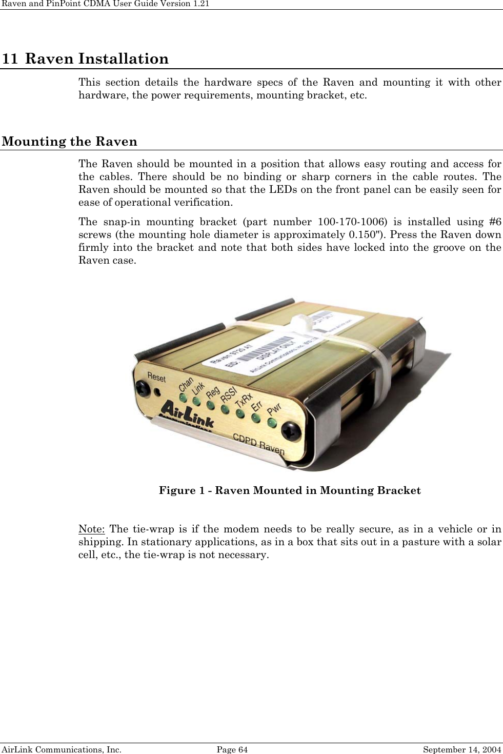
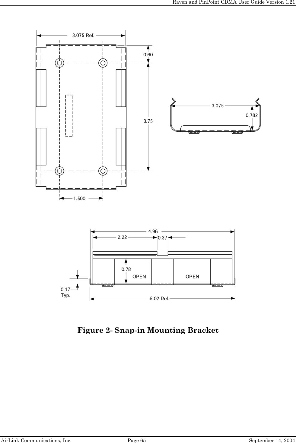
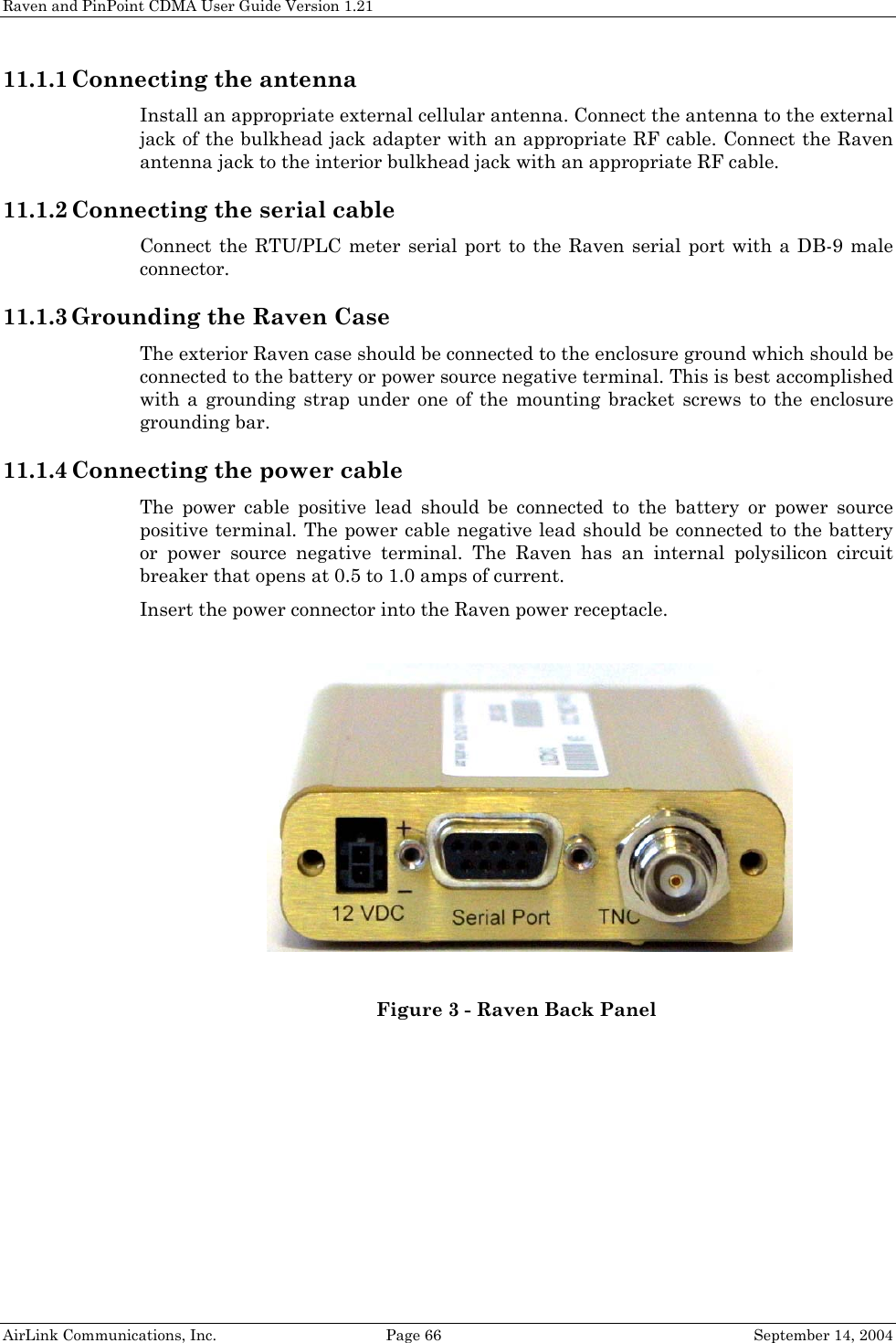
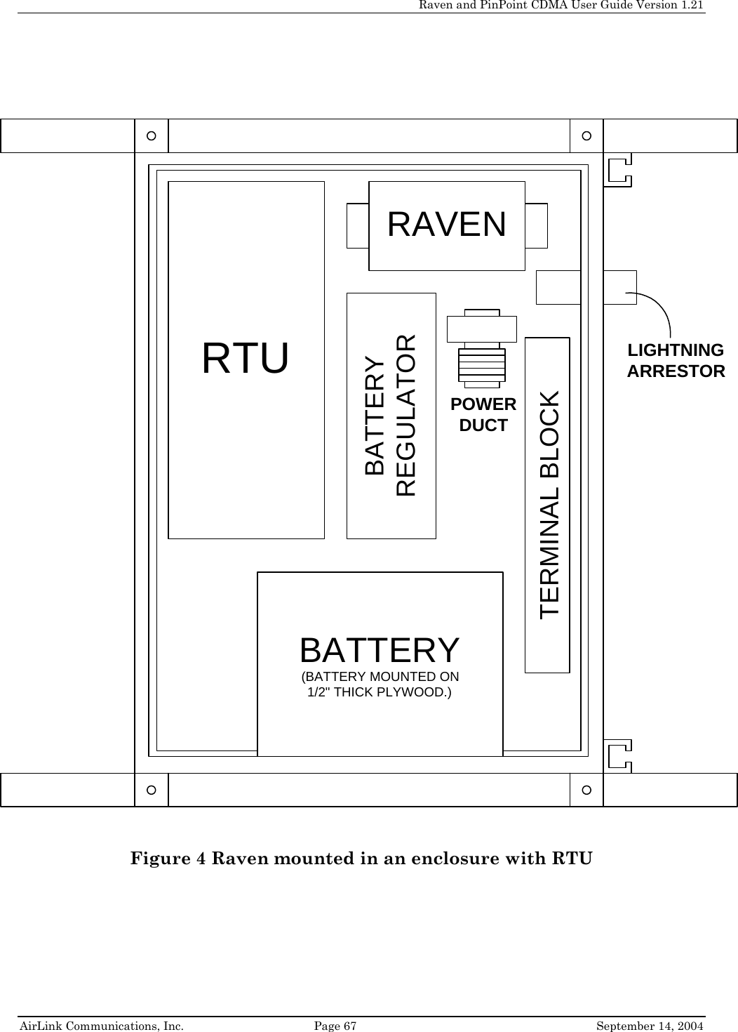

![Raven and PinPoint CDMA User Guide Version 1.21 AirLink Communications, Inc. Page 72 September 14, 2004 13 Raven CDMA Technical Specifications 13.1 Physical Characteristics • Rugged aluminum case • Weight: < 1 lb. • Size: 3.0” wide x 1” high x 5.5" long • RF Antenna Connector: 50 Ohm TNC • Serial Interface: RS232 DB-9F 13.2 Power Specifications • Advanced Power Management features • Input Voltage: 10 VDC to 28 VDC • Input Current: 50 mA to 350 mA at 12V • Typical Transmit/Receive: 250ma at 12VDC • Dormant connection [idle for 10-20 seconds] 50 ma at 12 VDC 13.3 Environmental • Operating ranges: -30°C to +70°C* • (<10%duty cycle limit above 60 °C) • Humidity: 5%-95%Non-condensing Model C3210 A thermistor inside the modem (monitored by the modem CPU firmware) causes flow control to be activated should the internal temperature reach 75ºC (167ºF) as measured at the radio. Flow control is released when the temperature falls below 75. Should the temperature of the radio reach 80ºC (176ºF), the modem terminates the connection in order to protect components and avoid drifting outside radio specifications.](https://usermanual.wiki/Sierra-Wireless/Q2438.Raven-and-Pinpoint/User-Guide-468939-Page-80.png)
![Raven and PinPoint CDMA User Guide Version 1.21 AirLink Communications, Inc. Page 73 September 14, 2004 13.4 Status LED Display • Channel [Chan] LED Flashing = Searching for a channel On = Found a channel • Link LED Off = No 1x or CDMA service On = 1x or CDMA service is available on this channel • Registration (REG) LED: Off = No PPP link on CDMA network On = PPP link is established on CDMA network and have an IP address. • RSSI LED – Indicates signal strength. Signal strength is denoted as follows: • < -100: RSSI LED off • –99 to –90: Blink every 1200ms • –89 to –80: Blink every 600ms • –79 to –70: Blink every 300ms • >= -69: RSSI LED on solid • Transmit (TX) LED: Off = Not transmitting On = Transmitting (on RF) • Receive (RX) LED: Off = No incoming data On = Receive data (on host) • ERR LED Currently unused • Power (PWR): Off = Power off On = Power on 13.5 RF Features Models C3210, C3310 • Supports CDMA2000 1X, IS-95 Circuit Switched CDMA and SMS • 250 mW RF output (+24 dBm) • Full duplex transceiver • Dual-band support for both 800 MHz cellular and 1.9 GHz PCS bands • Data rates up to 153.6 kbps • FCC certified (FCC Identifier GGL-C3110) • Industry Canada certified (certification #4481A-C3110)](https://usermanual.wiki/Sierra-Wireless/Q2438.Raven-and-Pinpoint/User-Guide-468939-Page-81.png)
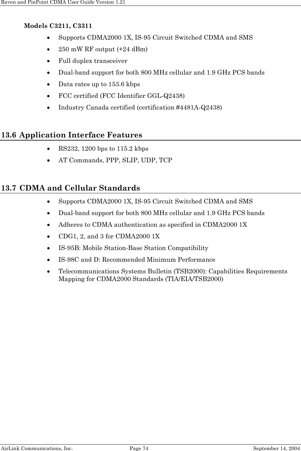
![Raven and PinPoint CDMA User Guide Version 1.21 AirLink Communications, Inc. Page 75 September 14, 2004 14 PinPoint CDMA Technical Specifications 14.1 Physical Characteristics: • Rugged aluminum case • Weight: < 2 lb. • Size: 3.3” wide x 2” high x 6.8" long • RF Antenna Connector: 50 Ohm TNC • Serial Interface: RS232 DB-9F 14.2 Power Specifications: • Advanced Power Management features • Input Voltage: 10 VDC to 28 VDC • Input Current: 20 mA to 600 mA • Typical Transmit/Receive: 300ma at 12VDC • Dormant connection [idle for 10-20 seconds] 150 ma at 12 VDC • Low power mode: 20 mA at 12 VDC 14.3 Environmental: • Operating ranges: -30°C to +70°C* • (<10%duty cycle limit above 60 °C) • Humidity: 5%-95%Non-condensing C3310 A thermistor inside the modem (monitored by the modem CPU firmware) causes flow control to be activated should the internal temperature reach 75ºC (167ºF) as measured at the radio. Flow control is released when the temperature falls below 75. Should the temperature of the radio reach 80ºC (176ºF), the modem terminates the connection in order to protect components and avoid drifting outside radio specifications.](https://usermanual.wiki/Sierra-Wireless/Q2438.Raven-and-Pinpoint/User-Guide-468939-Page-83.png)
![Raven and PinPoint CDMA User Guide Version 1.21 AirLink Communications, Inc. Page 76 September 14, 2004 14.4 Status LED Display: • Channel [Chan] LED Flashing = Searching for a channel On = Found a channel • Link LED Off = No 1x or CDMA service On = 1x or CDMA service is available on this channel • Registration (REG) LED: Off = No PPP link On = PPP link is established and have an IP address. • Transmit (TX) LED: Off = Not transmitting On = Transmitting (on RF) • Receive (RX) LED: Off = No incoming data On = Receive data (on host) • GPS LED Off = No GPS fix On = Have GPS fix • Power (PWR): Off = Power off On = Power on 14.5 RF Features: Model C3310 • Supports CDMA2000 1X, IS-95 Circuit Switched CDMA and SMS • 250 mW RF output (+24 dBm) • Full duplex transceiver • Dual-band support for both 800 MHz cellular and 1.9 GHz PCS bands • Data rates up to 153.6 kbps Model C3311 • Supports CDMA2000 1X, IS-95 Circuit Switched CDMA and SMS • 250 mW RF output (+24 dBm) • Full duplex transceiver • Dual-band support for both 800 MHz cellular and 1.9 GHz PCS bands • Data rates up to 153.6 kbps 14.6 Application Interface Features: • RS232, 1200 bps to 115.2 kbps • AT Commands, PPP, SLIP, UDP, TCP](https://usermanual.wiki/Sierra-Wireless/Q2438.Raven-and-Pinpoint/User-Guide-468939-Page-84.png)