Sierra Wireless R1902G GSM 850/1900 Data Modems User Manual Raven GPRS User Guide
Sierra Wireless, Inc. GSM 850/1900 Data Modems Raven GPRS User Guide
Contents
- 1. Exhibit 8 User manual 3210
- 2. Exhibit 8 User manual 3310
- 3. Exhibit 8 User manual 3110
Exhibit 8 User manual 3210

R
Ra
av
ve
en
n
G
GP
PR
RS
S
User Guide
Version 1.08
AirLink Communications, Inc.
September 29, 2003
AirLink
Communications
Information in this document is subject to change without notic
© Copyright AirLink Communications, Inc, 1993-2003. All rights reserved.
Please send comments to:
email: pubs@AirLink.com
Fax: 510-226-4299
Phone: 510-226-4200
Post: AirLink Communications, Inc.
Attention: Technical Publications Dept.
472 Kato Terrace
Fremont, CA 94539
Important Notice
Because of the nature of wireless communications, transmission and reception of
data can never be guaranteed. Data may be delayed, corrupted (i.e., have errors) or
be totally lost. Although significant delays or losses of data are rare when wireless
devices such as the AirLink Communications modem are used in a normal manner
with a well-constructed network, the AirLink modem should not be used in situations
where failure to transmit or receive data could result in damage of any kind to the
user or any other party, including but not limited to personal injury, death, or loss of
property. AirLink Communications, Inc., accepts no responsibility for damages of any
kind resulting from delays or errors in data transmitted or received using the
AirLink Communications modem, or for failure of the AirLink Communications
modem to transmit or receive such data.
Safety and Hazards
Do not operate the AirLink Communications modem in areas where blasting is in
progress, where explosive atmospheres may be present, near medical equipment,
near life support equipment, or any equipment which may be susceptible to any form
of radio interference. In such areas, the AirLink Communications modem MUST BE
POWERED OFF. The AirLink Communications modem can transmit signals that
could interfere with this equipment. Do not operate the AirLink Communications
modem in any aircraft, whether the aircraft is on the ground or in flight. In aircraft,
the AirLink Communications modem MUST BE POWERED OFF. When operating,
the AirLink Communications modem can transmit signals that could interfere with
various onboard systems. The driver or operator of any vehicle should not operate the
AirLink Communications modem while in control of a vehicle. Doing so will detract
from the driver or operator's control and operation of that vehicle. In some states and
provinces, operating such communications devices while in control of a vehicle is an
offence.
Limitation of Liability
The information in this manual is subject to change without notice and does not
represent a commitment on the part of AirLink Communications, Inc. AIRLINK
COMMUNICATIONS, INC. SPECIFICALLY DISCLAIMS LIABILITY FOR ANY
AND ALL DIRECT, INDIRECT, SPECIAL, GENERAL, INCIDENTAL,
CONSEQUENTIAL, PUNITIVE OR EXEMPLARY DAMAGES INCLUDING, BUT
NOT LIMITED TO, LOSS OF PROFITS OR REVENUE OR ANTICIPATED
PROFITS OR REVENUE ARISING OUT OF THE USE OR INABILITY TO USE
ANY AIRLINK COMMUNICATIONS, INC. PRODUCT, EVEN IF AIRLINK
COMMUNICATIONS, INC. HAS BEEN ADVISED OF THE POSSIBILITY OF
SUCH DAMAGES OR THEY ARE FORESEEABLE OR FOR CLAIMS BY ANY
THIRD PARTY.
Raven GPRS User Guide
Table of Contents
1. Introduction ..................................................................................... 5
1.1 Raven Product Overview ............................................................................... 6
2. Network Connection ...................................................................... 7
2.1 Internet (TCP/IP) Connections via GPRS .................................................... 7
2.2 Data Connections........................................................................................... 7
3. Raven and PinPoint GPRS Configuration ................................ 9
3.1 Local Configuration ....................................................................................... 9
3.2 Modem Activation........................................................................................ 11
3.2.1 SIM Check 12
3.2.2 PDP Context 12
3.3 Remote Configuration.................................................................................. 13
4. Windows Dial-Up Networking Setup ........................................ 14
4.1 Add Windows Modem Driver ...................................................................... 14
4.1.1 Setup Modem 14
4.1.2 Add Modem Driver 14
4.2 Windows Dial-Up Networking (PPP) Configuration ................................. 17
4.3 Making a GPRS Data Connection............................................................... 25
5. Dynamic IP Addresses ................................................................. 26
5.1 IPManager and Dynamic DNS Updates..................................................... 27
5.2 Using Names in the Modem, Domain Name Resolving............................. 27
6. Serial Communication Modes .................................................... 29
6.1 AT Mode ....................................................................................................... 30
6.2 PPP Mode ..................................................................................................... 30
6.3 PassThru Mode ............................................................................................ 31
6.4 UDP PAD Mode ........................................................................................... 31
6.4.1 UDP Auto Answer 32
6.4.2 Reliable UDP 32
6.4.3 Multicast UDP [Raven Only Feature] 33
6.5 TCP PAD Mode ............................................................................................ 33
6.6 TCP Auto Answer ........................................................................................ 34
6.7 Hybrid Modes............................................................................................... 34
6.8 SLIP Mode.................................................................................................... 35
6.9 Modbus/BSAP Configuration [Raven Only Feature] ................................. 35
6.9.1 Configuring the Polling Host Application Raven 35
6.9.2 Configuring the Remote Ravens 36
7. Using AT Commands .................................................................... 38
7.1 GPRS Specific AT Commands..................................................................... 39
7.2 Raven and PinPoint AT Command Reference............................................ 41
8. Raven Installation......................................................................... 52
8.1 Mounting the Raven .................................................................................... 52
8.2 Connecting the antenna .............................................................................. 54
8.3 Connecting the serial cable ......................................................................... 54
8.4 Grounding the Raven Case ......................................................................... 54
8.5 Connecting the power cable......................................................................... 54
9. Raven GPRS Technical Specifications..................................... 57
9.1 Physical Characteristics .............................................................................. 57
9.2 Power Specifications .................................................................................... 57
9.3 Environmental ............................................................................................. 57
9.4 RF Features ................................................................................................. 57
9.5 Status LED Display..................................................................................... 58
9.6 Application Interface Features ................................................................... 58
Raven GPRS
User Guide
1. Introduction
The GSM/GPRS wireless network combines the world’s leading wireless standard—
the Global System for Mobile Communications (GSM)—with fast, packet-switched
access to data networks such as the Internet. Providing this fast access is the
General Packet Radio Service (GPRS).
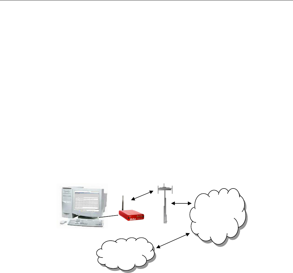
The AirLink GPRS modems are designed to operate in GSM/GPRS networks. Two
data services are available in the GSM/GPRS networks: GPRS, a packet switched
connection, and SMS, a short message service..
GPRS
GPRS is an IP-based service that offers fast, packet-switched access to data networks
such as the Internet. It is a mobile service that improves the peak-time capacity of a
GSM network. GPRS gives packet-switched access over GSM to external data
networks with high peak transfer capacity. The main objective of GPRS is to offer
access to standard data networks such as TCP/IP. GPRS is a non-voice service
designed specifically for transmitting data. It breaks data messages into separate
packets for transmission from the mobile device and sends them to destinations in an
external network.
Most any Internet-based application or service will run on GPRS. GPRS offers peak
throughputs of 40 Kbps (53.6 Kbps raw) Because GPRS capacity is shared among
active users in the same coverage area, actual throughputs may vary.
GPRS
Network
Internet
Raven Product Overview Raven GPRS User Guide Version 1.08
AirLink Communications, Inc. Page 6 September 29, 2003
1.1 Raven Product Overview
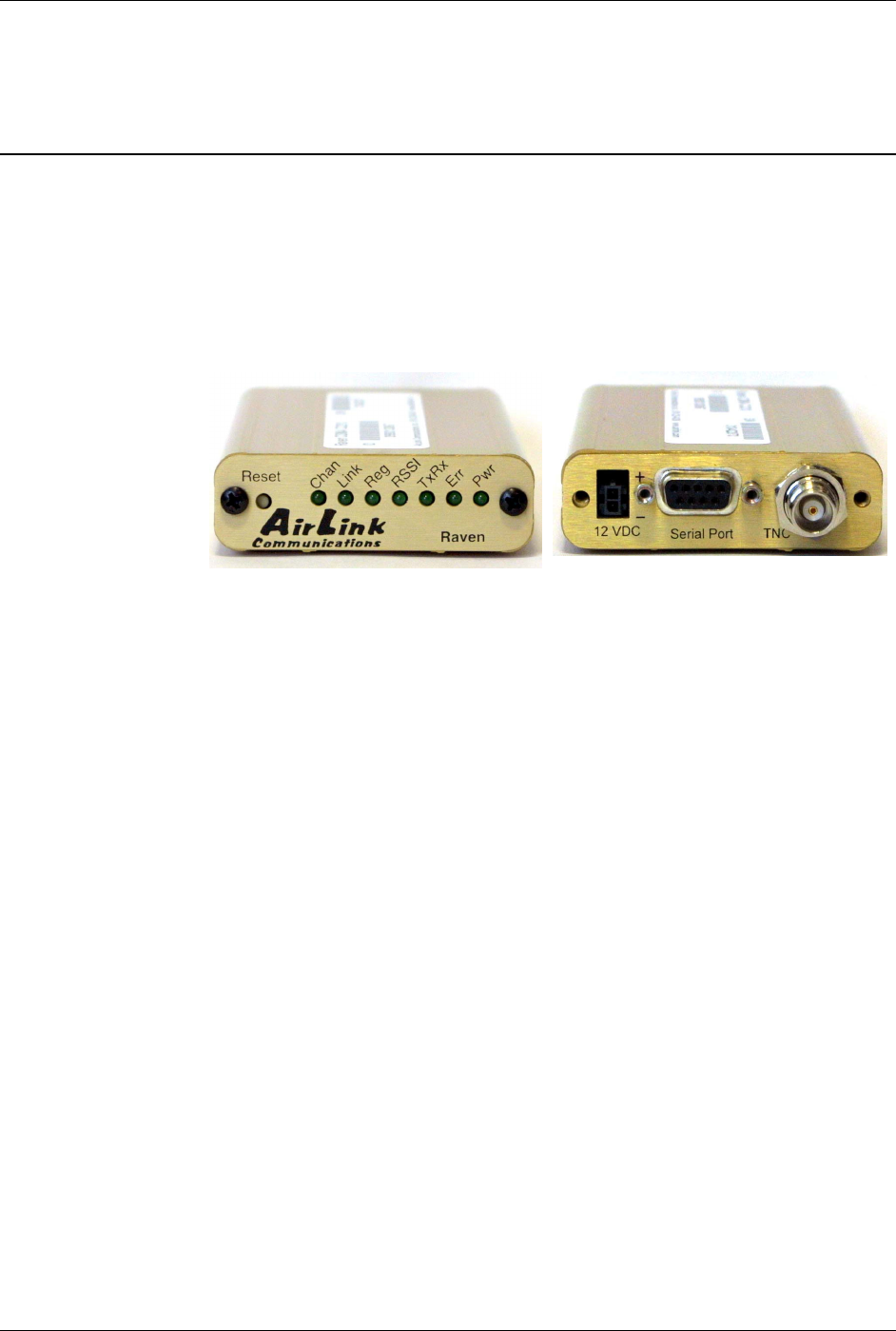
The AirLink Raven GPRS is a rugged, full duplex GPRS modem that provides
wireless transport capabilities for fixed and mobile applications. GPRS is an efficient
and secure wireless technology that works well for fixed or mobile applications.
The Raven's rugged form factor is ideal for industrial and commercial applications
that require real-time communications. The Raven provides wireless data
communications for a variety of applications, such as telemetry, public safety,
SCADA, traffic control, traffic metering, transit arrival systems and more.
Front of Raven Back of Raven
Network Connection Raven GPRS User Guide Version 1.08
AirLink Communications, Inc. Page 7 September 29, 2003
2. Network Connection
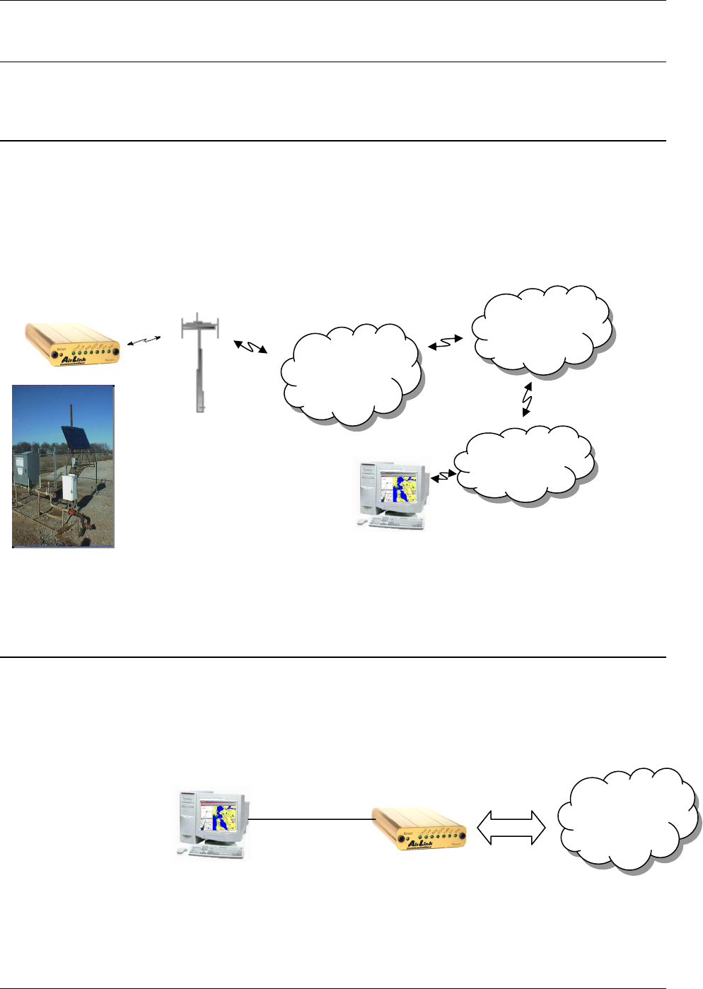
The AirLink GPRS modems are capable of providing network connections for GPRS
and SMS data.
2.1 Internet (TCP/IP) Connections via GPRS
When using a Raven or PinPoint GPRS modem, remote access to is done via a PPP
(TCP/IP) connection to the GPRS network. The GPRS carrier actually provides
Internet connectivity, and, therefore, it becomes the ISP for that session.
Applications such as web browsing, email, FTP, etc., should work as they would
normally.
NOTE: Connections to Internet are provided by carrier.
Corporate network connections are unique and not provided as part of service.
2.2 Data Connections
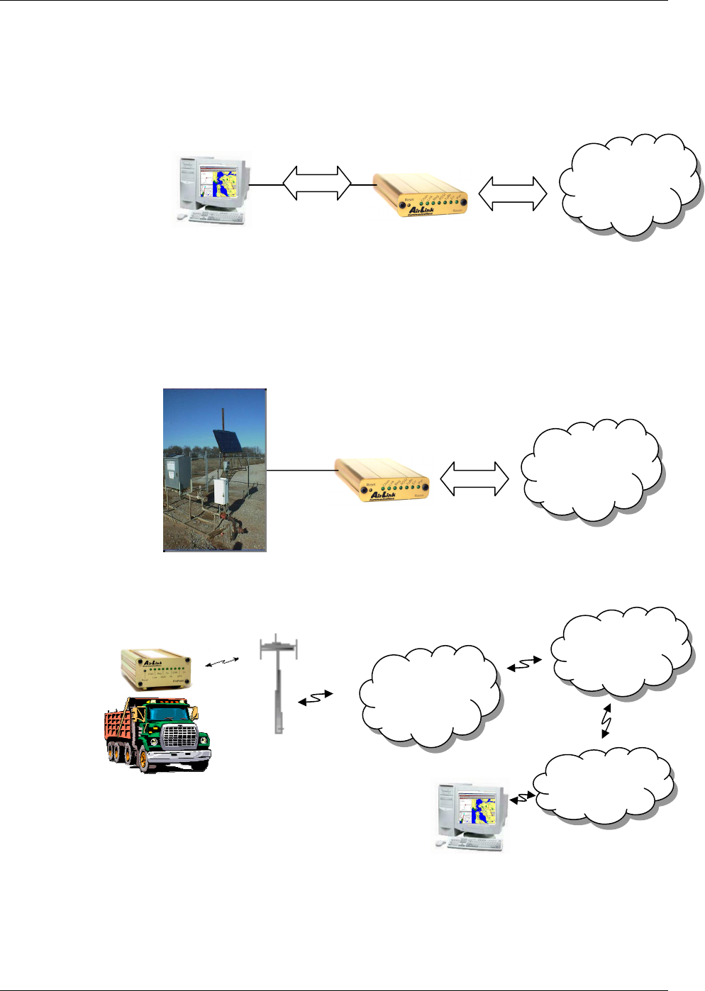
When the Raven is powered on, it automatically searches for GPRS service and
establishes a PPP link between the Raven and the network. The Raven obtains its
public or private IP and is ready to communicate.
GSM GPRS
Network
PPP
IP
GSM GPRS
Network
Internet
Corporate
LAN
Data
Acquisition
App
Network Connection Raven GPRS User Guide Version 1.08
AirLink Communications, Inc. Page 8 September 29, 2003
If the host establishes a PPP link to the Raven, a second PPP link is created between
the Raven and the host. IP packets can then be sent to and received from the GPRS
network.
If the host device is to send and receive data via the Raven or PinPoint, then the
modem can be configured to use either one of the UDP or TCP packet
assembly/disassembly modes.
GSM GPRS
Network
PPP
PPP IP
IP
GSM GPRS
Network
PPP
UDP or
TCP
Data
IP
GSM
GPRS
Network
Internet
Corporate
LAN
ATS
Raven and PinPoint GPRS Configuration Raven GPRS User Guide Version 1.08
AirLink Communications, Inc. Page 9 September 29, 2003
3. Raven and PinPoint GPRS Configuration
Configuration of the Raven and PinPoint GPRS modem is done using a terminal
emulation program like HyperTerminal in Windows.
IMPORTANT NOTE: At this time Wireless ACE cannot be used to configure
the GPRS modems from a Windows computer. A future version of Wireless
ACE will be available with this functionality.
However, remote configuration of the modem is possible with a telnet
application. (See Section 3.3.)
3.1 Local Configuration
1. Attach the antennas, DB-9 cable and power to the back of the modem.
2. Power on the modem, and ensure the On light is lit.
3. Attach the modem to the back of the PC with the provided DB-9 cable.
(Note, if you did not order a cable with your modem, you need a straight-thru
RS-232 cable to attach to the modem.)
4. Select Start→ Programs→ Accessories→ Communications→
HyperTerminal.
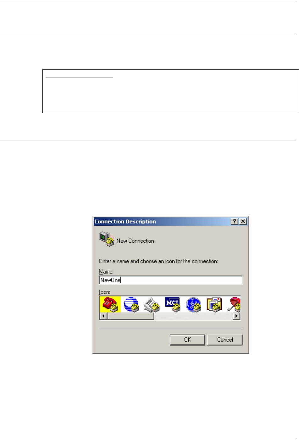
5. Enter the name of the connection and select OK.
Raven and PinPoint GPRS Configuration Raven GPRS User Guide Version 1.08
AirLink Communications, Inc. Page 10 September 29, 2003
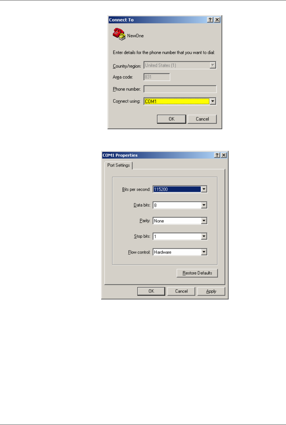
6. For "Connect using" select the COM port that the modem is on (do not select
a modem driver), then select OK.
7. Select 115200 for the "Bits per second." Ensure Data Bits: 8, Parity: None,
Stop bits: 1 and Flow control: Hardware. Then select OK.
(These are the factory default settings for a GPRS modem. If you get garbled
characters when typing AT commands, change these settings and reconnect
to the modem. For example, change the baud rate to 57,600 bits per second
and connect again, etc.)
Raven and PinPoint GPRS Configuration Raven GPRS User Guide Version 1.08
AirLink Communications, Inc. Page 11 September 29, 2003
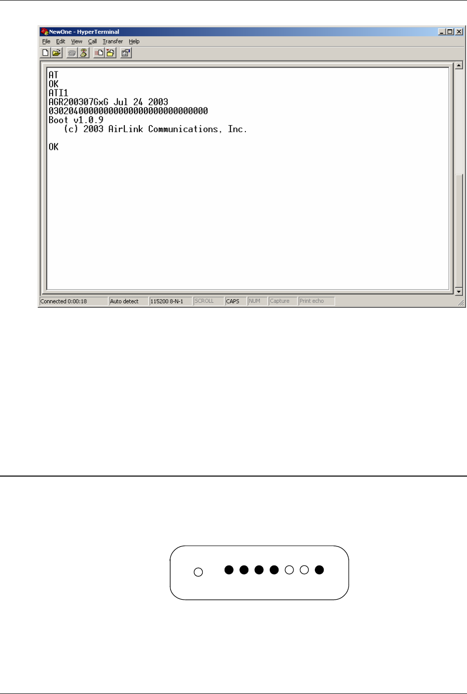
8. Type AT followed by [Enter]. You should receive an "OK" in response.
9. Type ATI1 followed by [Enter]. This displays the modem firmware version
and you should also see "AirLink Communications, Inc." in it which ensures
you are talking to the AirLink modem. (If not, try changing COM ports.)
Other AT commands may now be issued to the modem. See Section Using AT
Commands for a list of AT commands
3.2 Modem Activation
The GPRS modem is usually already set up to register online with a phone number,
etc. pre-configured into it (by AirLink Communications, Inc.). When a modem is
registered on the network and working, the lights will look like the following:
Note that the RSSI light may be flashing or solid, showing the strength of the signal.
Also the Tx/Rx (transmit/receive) light will flash as data is transferred to and from
the modem on the network.
A
ir
L
ink
C
ommunications

Raven and PinPoint GPRS Configuration Raven GPRS User Guide Version 1.08
AirLink Communications, Inc. Page 12 September 29, 2003
If your modem lights look like the above when the modem is powered on, you do NOT
need to configure the modem and may skip this section.
If, however, the Reg light is not lit, your modem may need a SIM, or you may need to
select the PDP context.
• Connect up to configure the modem as in Section 3.1.
• If you are unfamiliar with using AT commands, please review Section Using
AT Commands first.
3.2.1 SIM Check
You can check if a SIM [Subscriber Identity Module] is in the modem with the
AT+CIMI? command. If a SIM is in the modem, you will see a response like the
following:
at+cimi?
310380006255650
OK
The number is an abbreviated form of the IMSI [International Mobile Subscriber
Identity] which is unique to each SIM.
If there is no SIM, there will be a blank response like the following:
at+cimi?
OK
3.2.2 PDP Context
Check if the PDP context is correct with the command:
AT+CGDCONT?
You should get a response like:
at+cgdcont?
1,IP,proxy
OK
If you get a blank response, you need to set the PDP context. You need the APN
[Access Point Name] which you can obtain from the carrier rep or from whomever
you received the account. Most companies will be using a custom APN that allows
them to communicate with all
To set the PDP context:
at+cgdcont=1,”IP”,”apn_obtained_from_carrier”
at&w
You only need to do this once. Henceforth, the modem will use this setting to attach
to the GPRS network.

Raven and PinPoint GPRS Configuration Raven GPRS User Guide Version 1.08
AirLink Communications, Inc. Page 13 September 29, 2003
3.3 Remote Configuration
Once the modem is online and registered, it can be contacted from a remote location
via a setup that connects to the GPRS network using the same APN as the target
modem. This can be accomplished by one of the following means:
• A frame relay link to the carrier’s GPRS network
• A VPN [Virtual Private Network] connection to the carrier’s GPRS
network
• Another GPRS modem
where each of the above means is using the same APN as the target modem.
Using a telnet application, a connection can be made to the modem and then AT
commands can be issued to configure the modem, just as if a local connection were
being made to the modem.
(Note: If you wish to use Wireless ACE, please see the Important Note in Section 2.)
1. From a Command Prompt, type:
telnet “Host Address” “Port Number”
2. For the "Host address" enter the IP address of the modem. (AT*NETIP?
will reveal the current device IP address.)
3. For the "Port Number" use 2332. This is the default telnet port number
for the GPRS modems. So it would look something like this:
• telnet 192.168.100.23 2332
4. If the correct parameters have been entered, and the modem is currently
online, you will get a "Password" prompt as shown below:
AirLink AT command Interpreter
Password *****
OK
5. Enter 12345 (default password) and press [Enter]. You will receive an
OK.
Now you may enter any AT commands to the modem as you would if you were doing
a local connection to the modem. See Section Using AT Commands for AT
commands and their options.
You may want to set local echo in your terminal emulator to see what you type as you
type. There is no remote echo function in the modem.
Note: If the modem is configured to use a DDNS [Dynamic Directory Name Server],
you could use a name in place of the IP address above, as in:
telnet remote1.eairlink.com 2332
Windows Dial-Up Networking Setup Raven GPRS User Guide Version 1.08
AirLink Communications, Inc. Page 14 September 29, 2003
4. Windows Dial-Up Networking Setup
This section describes the setup of Windows to enable communications over the
GPRS network. Windows 2000 is used as the example because it the one Windows
OS revision that carries the most similarity to both Windows 98 as well as Windows
XP.
4.1 Add Windows Modem Driver
4.1.1 Setup Modem
Connect the modem to the computer with the DB-9 cable.
Plug in the AC adapter, connect the antenna(s) and power on the modem.
Obtain administrator privileges on your system.
If you do not know how, check with your system administrator.
4.1.2 Add Modem Driver
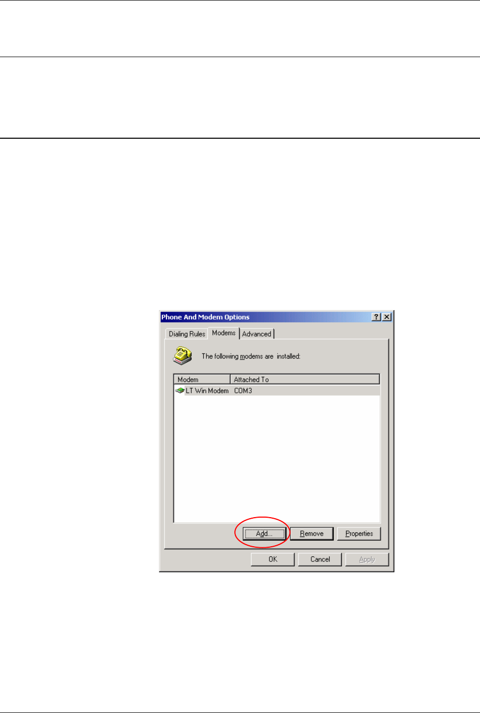
1. Select Start→ Settings→ Control Panel→ Phone and Modems Options.
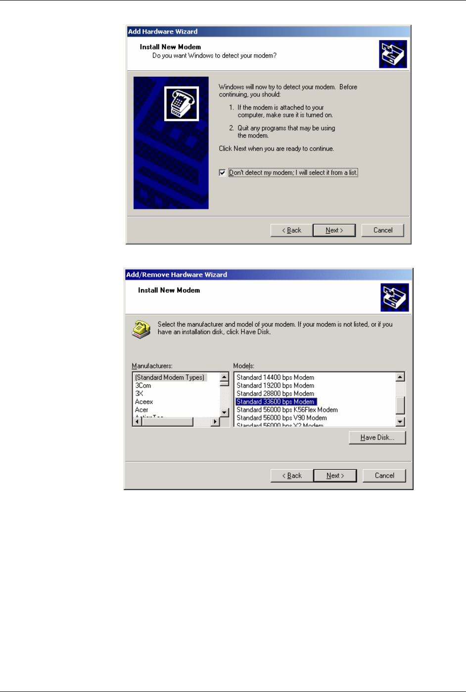
2. You should see be in the Phone And Modem Options dialog box. Select the
"Modems" tab.
3. Select Add.
Windows Dial-Up Networking Setup Raven GPRS User Guide Version 1.08
AirLink Communications, Inc. Page 15 September 29, 2003
4. Check "Don't detect my modem..." and select Next.
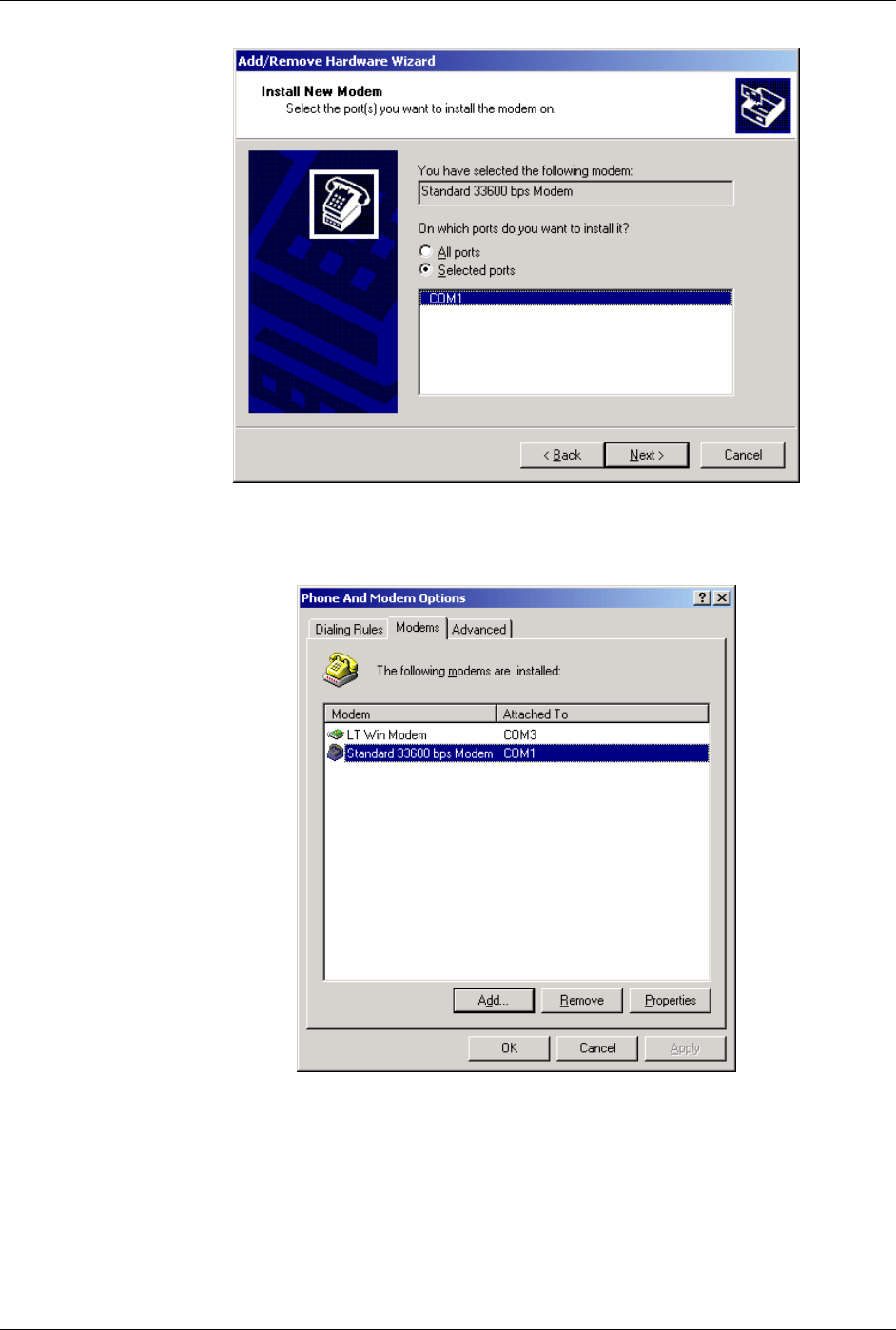
5. Select "(Standard Modem Types)" from the Manufacturers and then select
"Standard 33600 bps Modem" under Models.
6. Select Next.
Windows Dial-Up Networking Setup Raven GPRS User Guide Version 1.08
AirLink Communications, Inc. Page 16 September 29, 2003
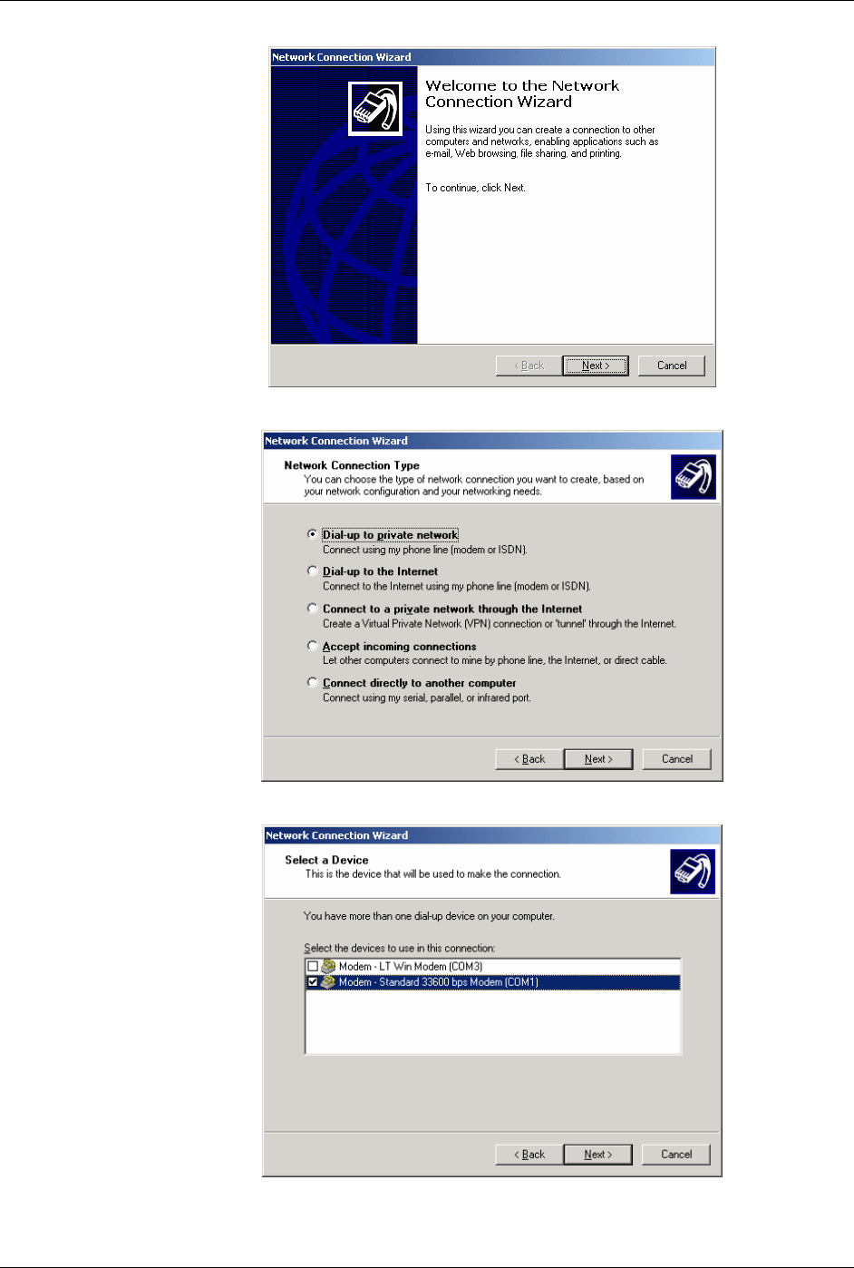
7. Check Selected Ports, then select the COM port the modem is connected to and
select Next.
8. Select Finish to exit the "Install New Modem" wizard.
9. You should see the modem added to the correct COM port.
10. To set the modem speed on the driver, highlight the modem driver and select
Properties.
11. Ensure the "Maximum Port Speed" is set to 115200, which is the default value of
the GPRS modems.
12. Select OK to exit.

Windows Dial-Up Networking Setup Raven GPRS User Guide Version 1.08
AirLink Communications, Inc. Page 17 September 29, 2003
4.2 Windows Dial-Up Networking (PPP) Configuration
This section describes how to setup a Windows Dial-up Networking connection for an
AirLink GPRS Modem. Windows 2000 Professional was used in this example. The
connection uses PPP to communicate to the modem and gain access the Internet.
Before you start, you need the following:
1. Administrator privileges to the computer you are configuring or access
granted by an administrator on the network to add/remove devices to your
computer. (Not necessary on Windows 98/ME.)
2. Windows COM Port and modem set up for a Standard 33600 Modem (see
Section 4.1).
3. No other program is to be running that is using the serial (COM) port that
your modem is attached to.
Now that the modem has been added, the Dial-up connection must be created.
1. Select Start→ Settings→ Control Panel→ Network and Dial-Up
Connections.
2. Double-click on the "Make New Connection" icon.
NOTE: If you have an existing LAN connection, then this dial-up connection to
your GPRS modem may interfere with your existing connection. Once the
connection is initiated it will take over as the "default route" for the majority of
your LAN traffic, specifically Internet access. It's recommended to disconnect
your LAN connection before using a PPP connection with your AirLink modem.
If however you want the two connections to co-exist, you can de-select "Use
default gateway on remote network" (described later) and you can use the
route command to setup routing through the modem properly. Go to a
Command Prompt and type route /? to find out more, or talk to your
administrator.
Windows Dial-Up Networking Setup Raven GPRS User Guide Version 1.08
AirLink Communications, Inc. Page 18 September 29, 2003
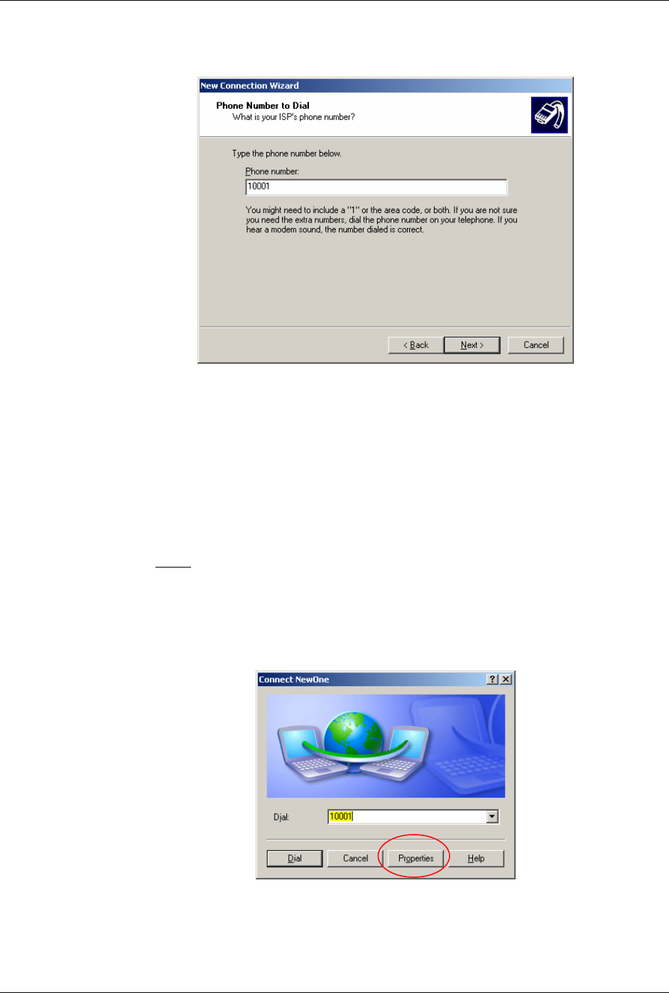
3. When the Connection Wizard starts, select Next.
4. Select "Dial-up to private network" and select Next.
Windows Dial-Up Networking Setup Raven GPRS User Guide Version 1.08
AirLink Communications, Inc. Page 19 September 29, 2003
5. Check the box next to "Modem – Standard 33600bps" and select Next.
6. Enter the Phone Number: 10001 and then select Next.
7. Select whether you want all users or just yourself to have access to this
connection, and select Next.
8. Enter NewOne for the name of the connection. If you want to add an icon
for this connection on the desktop, check "Add a shortcut to my
desktop."
9. Select Finish to exit the "Network Connection Wizard."
Note: Now some manual configuration changes need to be made to the
connection before it can be used.
10. The "Connect NewOne" dialog box should come up next.
11. Leave the User name and Password blank.
12. Select Properties.
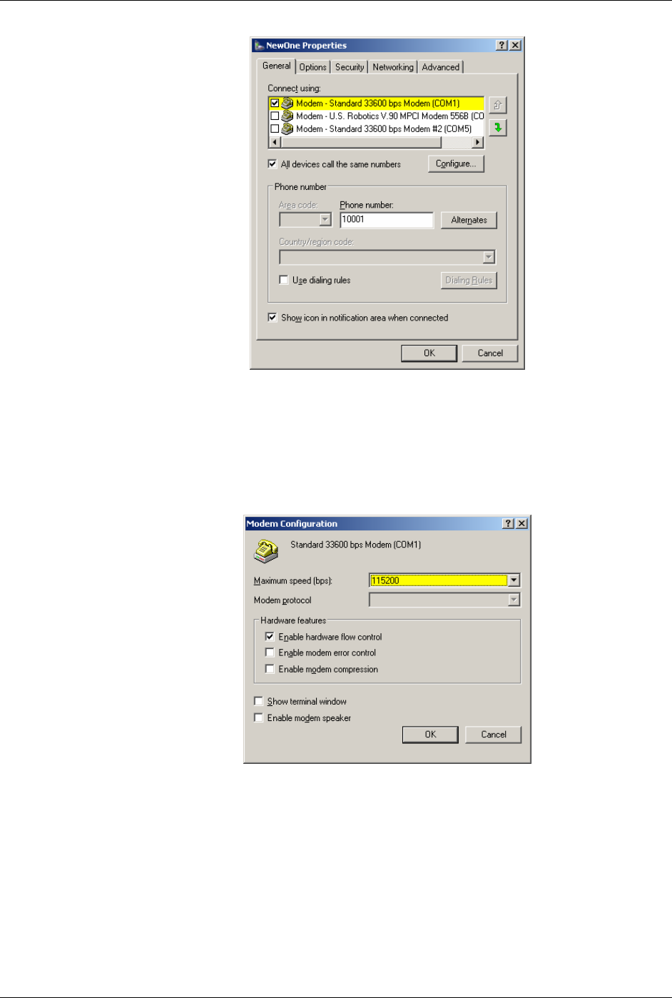
13. Examine the General tab settings.
Windows Dial-Up Networking Setup Raven GPRS User Guide Version 1.08
AirLink Communications, Inc. Page 20 September 29, 2003
14. “Connect using” should have a check next to “Modem – Standard
33600bps Modem (COMx).”
15. Enter “10001”for the “Phone number”.
16. Uncheck "Use dialing rules" and check “Show icon in taskbar when
connected.”
17. Select the Configure button.
18. Maximum Speed: 115200.
19. Check Enable hardware flow control.
20. Uncheck all other options.
21. Select OK.
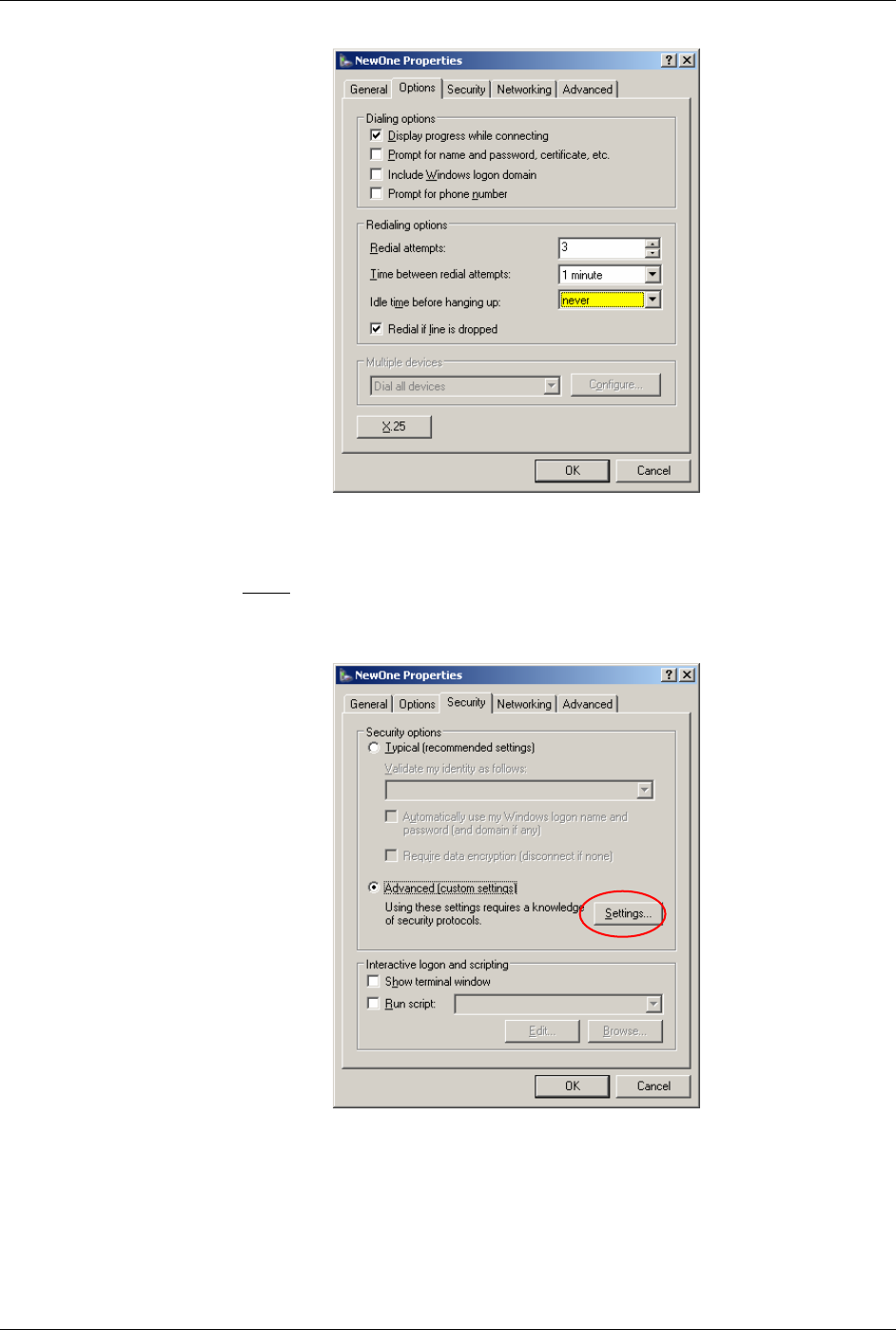
22. Select the Options tab.
Windows Dial-Up Networking Setup Raven GPRS User Guide Version 1.08
AirLink Communications, Inc. Page 21 September 29, 2003
23. Check or Uncheck options as your application requires.
24. Set the "Redialing options" that will meet your needs.
Note: The options shown here should work for most applications. Consult
your Network Administrator for more help on connection options.
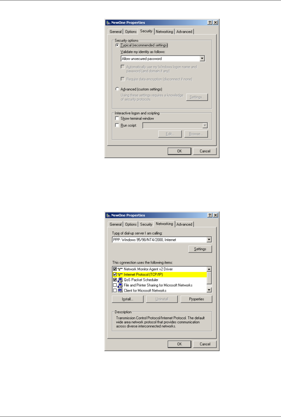
25. Select the Security tab.
26. Select “Advanced (custom settings).”
Windows Dial-Up Networking Setup Raven GPRS User Guide Version 1.08
AirLink Communications, Inc. Page 22 September 29, 2003
27. For "Security Optioins" check “Typical recommended settings”
28. In “Validate my identity as follows:”, select “Allow unsecured
password”. Your identity and security is taken care of in the SIM.
29. Select OK.
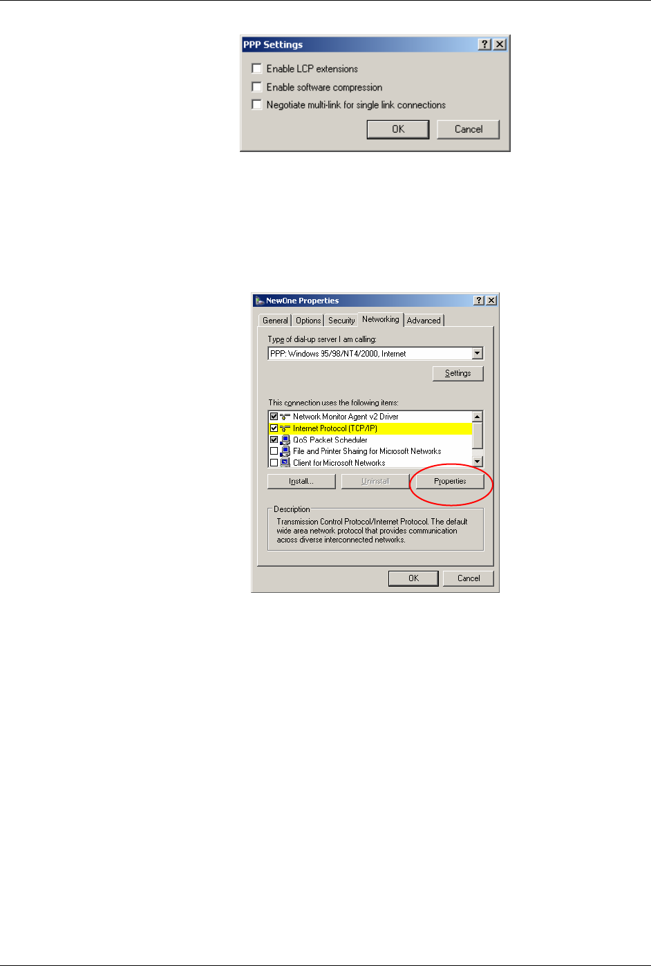
30. Select the Networking tab.
31. Type of dial-up server should show “PPP: Windows 95/98/NT 4/2000,
Internet.”
32. Select the Settings button.
Windows Dial-Up Networking Setup Raven GPRS User Guide Version 1.08
AirLink Communications, Inc. Page 23 September 29, 2003
33. Uncheck all three of the PPP Settings options.
34. Select OK.
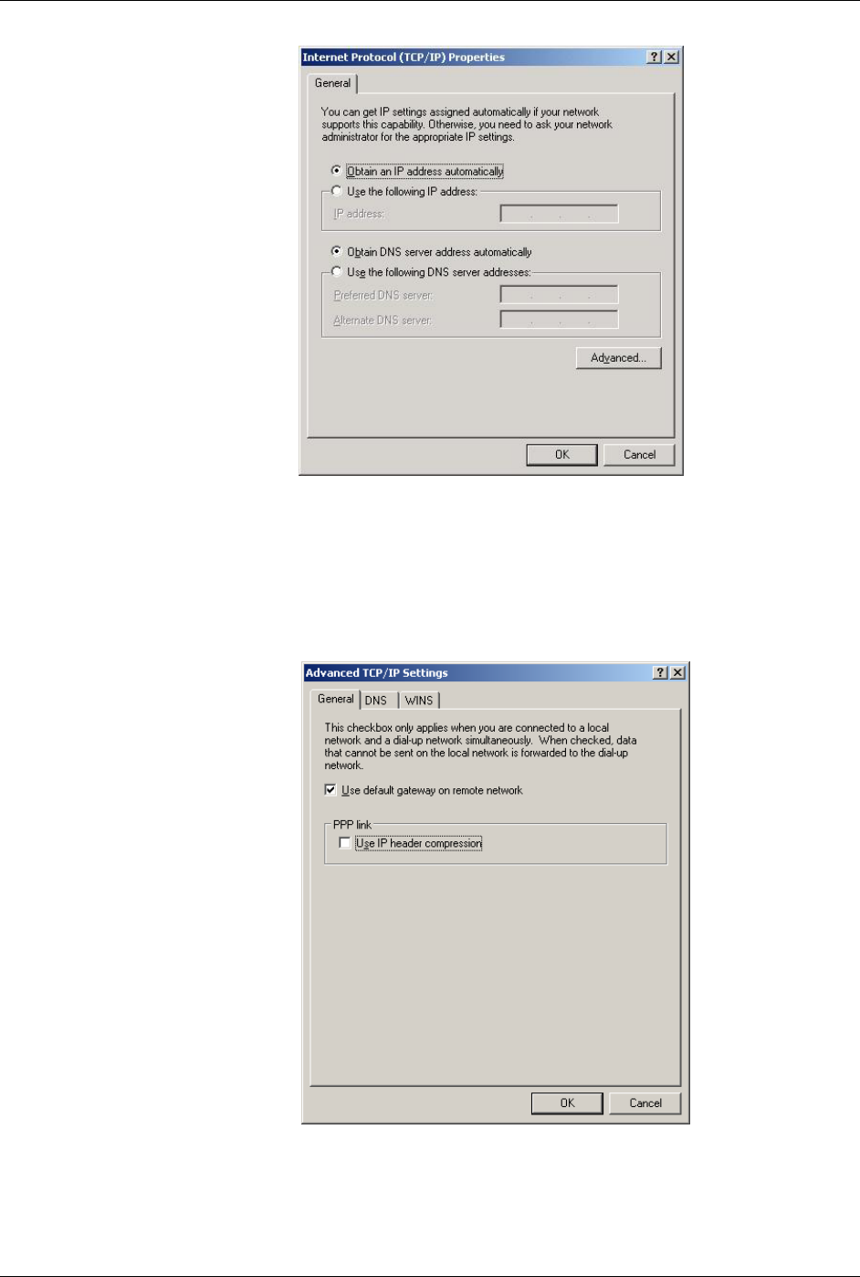
35. In the Components section of the Networking tab, Internet Protocol
(TCP/IP) should be checked.
36. Select (highlight) Internet Protocol (TCP/IP) and then select
Properties.
Windows Dial-Up Networking Setup Raven GPRS User Guide Version 1.08
AirLink Communications, Inc. Page 24 September 29, 2003
37. "Obtain an IP address automatically" should be checked.
38. Normally, DNS server addresses are provided during PPP negotiations. If
it is necessary for you to enter DNS entries, check/enable "Use the
following DNS server addresses" and put in the proper addresses.
(See your carrier or Network Admin for details.)
39. Select the Advanced button.
40. Check Use default gateway on remote network and uncheck Use IP
header compression.

Windows Dial-Up Networking Setup Raven GPRS User Guide Version 1.08
AirLink Communications, Inc. Page 25 September 29, 2003
41. Select OK.
42. Leave the options under the Sharing tab unchecked.
43. Select OK.
4.3 Making a GPRS Data Connection
To make a GPRS data connection.
1. Go to Network and Dial-Up Connections and double-click on the NewOne
icon.
2. Click on Dial.
If you have enabled the connection progress display, you will see the
connection being made:
Once connected, you will see the connection status displayed in the System Tray on
the Task Bar.
Dynamic IP Addresses Raven GPRS User Guide Version 1.08
AirLink Communications, Inc. Page 26 September 29, 2003
5. Dynamic IP Addresses
Many modern wireless data technologies use dynamic IP addresses rather than static
IP addresses. This poses a problem for AirLink customers since they cannot contact
their modems unless their addresses are known. AirLink offers a family of solutions
designed for the different situations existing with our customers. One of the
solutions, an IPManager System that implements a wireless Dynamic Domain Name
Server, DDNS.
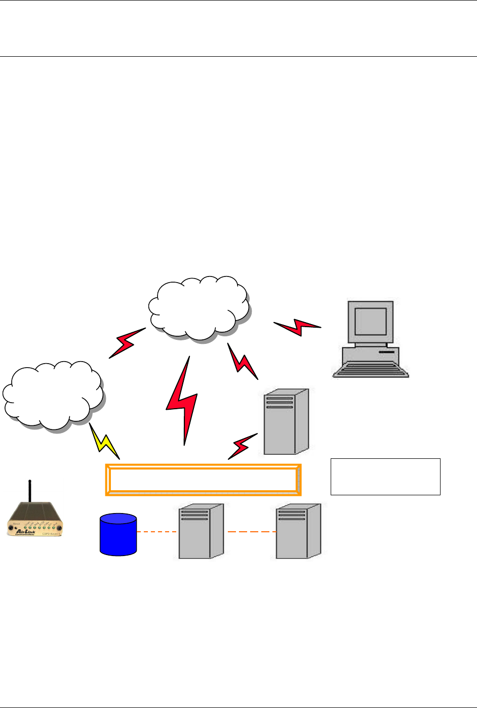
IPManager is a system which tracks the current IP address which a modem has been
assigned. The DDNS system consists of three main components. One component is a
task in the modem firmware which issues an update notification to the IPManager
server when the modem is assigned a new IP address. The second component is the
IPManager server which receives IP change notifications from all modems and
updates a DNS server, the third component. It may, optionally, log the latest known
IP address in a database, which may be accessed to see a history of the IP updates.
Customers may then use the wireless Dynamic DNS server to obtain the current IP
of an AirLink modem. The following diagram shows the IPManager system elements.
Internet
3G
Network
Firewall
DNS
IPManager
DB DNS
DNS Servers may be
inside or outside the
firewall

Dynamic IP Addresses Raven GPRS User Guide Version 1.08
AirLink Communications, Inc. Page 27 September 29, 2003
5.1 IPManager and Dynamic DNS Updates
The IPManager system provides a mechanism to implement a wireless Dynamic DNS
service. If the IPManager settings are configured, the modem will send IP change
notification messages to AirLink IPManager servers. These servers will then
acknowledge the notifications and dynamically update a DNS server, thus allowing
users to access a modem by domain name. The *IPMANAGER1 and
*IPMANAGER2 settings can be set to either the domain name or IP address of a
server to notify. The *MODEMNAME setting should be set to the name to prefix to
the domain zone for which the IP Manager server is responsible. For example, if
*MODEMNAME=mymodem and *IPMANAGER1 points to a server responsible
for the eairlink.com domain zone, then the modem’s fully qualified domain name
will be: mymodem.eairlink.com.
To configure your AirLink modem to addressed by name, the modem needs to have 4
elements configured:
1. Modem name
2. Domain
3. IPManager IP Address
4. IPManager update interval
The following illustrates a way to configure an AirLink modem to be addressed by
name:
at*modemname=mymodem
at*domain=eairlink.com
at*ipmanager1=eairlaink.com
at*ipmgrupdate=60 [to update the DNS server at least hourly]
5.2 Using Names in the Modem, Domain Name Resolving
The AirLink modems have an integrated DNS resolver, which uses the DNS entries
specified by the *DNS1, *DNS2, and *DNSUSER settings. This allows the use of
names in the AirLink modems instead of IP addresses.
Both regular and reverse DNS lookups are supported. ATNSLOOKUP command
will allow the lookup of an address or domain name. (e.g.
atnslookup=www.microsoft.com will return the IP address for
www.microsoft.com, while atnslookup=64.163.70.10 should return airlink.com). If
a name resolution is performed on a name which is not fully qualified (i.e. contains
no dotted portions), the value from *DOMAIN will be concatenated to the end.
Typically the *DNS1 and *DNS2 values will be automatically filled in when a
connection is negotiated with the carrier. The *DNSUSER value is provided to allow
the user to specify a DNS server to check with before resorting to the carrier provided
servers. If *DNSUSER is set to 0.0.0.0, it will be ignored and only the carrier DNS’s
will be consulted. If it is set, the name server at the provided address will be queried
first. If it doesn’t respond (within the timeout period, 10s) or can’t find the requested
entry, the carrier DNS’s will then be queried.
The special domain name “ppp-peer” will always resolve to the address to use to
communicate with the PPP (or SLIP) host peer connected to the host port. If there is
no PPP (or SLIP) peer (i.e. modem is not in PPP or SLIP mode), then “ppp-peer” will
resolve to 0.0.0.0. If, for example, you wanted to report IP address changes to the

Dynamic IP Addresses Raven GPRS User Guide Version 1.08
AirLink Communications, Inc. Page 28 September 29, 2003
host connected via the serial link, you could set AT*IPMANAGER2=ppp-peer to
cause updates to be sent to the serial host.

Serial Communication Modes Raven GPRS User Guide Version 1.08
AirLink Communications, Inc. Page 29 September 29, 2003
6. Serial Communication Modes
In this section the following terminology is used:
Host: This is the computer or terminal that is attached to the serial port of
the Raven. Also known as the DTE.
Modem: The Raven GPRS. The DCE to the host.
OEM
Modem: The embedded communications transceiver module.
Server: A computer to which a Raven is communicating wirelessly.
An AirLink modem can be in one of six serial communication modes with the
attached Host:
AT: The modem accepts and responds to standard, Hayes-style AT
commands. This is the default.
PPP: Modem is using PPP to communicate with the Host.
PassThru: Direct connection to internal OEM Module.
UDP PAD: Any data received on the serial port is assembled into UDP packets
and send to the session’s associated IP and Port (described later).
Any responses received from the associated IP and port destined for
the modem’s Device Port are unwrapped and sent out the serial
port.
TCP PAD: Any data received on the serial port is packaged into TCP messages
and sent to the associated connection’s IP and Port (described
later). Any data received from the TCP peer is unwrapped and sent
out the serial port.
SLIP: Modem is using SLIP to communicate with the Host.
The default mode is AT command. If the modem is in any of the other modes, the AT
command mode can be re-entered by:
• Deactivating DTR (if &D2 or Ignore DTR, S211, is not set)
• Issuing the +++ escape sequence (if Disable AT Escape, DAE, is
not set)
• Resetting or Power cycling the modem.
The PassThru mode can only be exited by resetting the modem
The modem can be programmed to enter one of the other modes automatically on
power up. This is done setting the Startup Mode Default (MD) to the desired mode.
If this setting is non-zero, the modem will enter the specified mode after 5 seconds. If
you want to cancel this behavior, the ATMD0 command can be used before the 5-
second timeout expires.
The modes are described in more detail in the following sections.

Serial Communication Modes Raven GPRS User Guide Version 1.08
AirLink Communications, Inc. Page 30 September 29, 2003
6.1 AT Mode
AT commands are used to configure the modem, command it to do something, or
query a setting.
AT commands must always be terminated by <CR> (ASCII character 0x0D).
If E=1 (Echo On), the AT command (including the terminating <CR>) will be output
before any responses defined in the next section.
Response Framing
Two settings affect the format of AT command output: V (Verbose) and Q (Quiet).
If Q=1 (Quiet On), no result codes are output whatsoever, so there is no response
generated by a (non query) command. If Q=0 (Quiet Off), result codes are output. The
format of this output if then affected by the Verbose setting.
If Quiet mode is off, the result code is affected as follows: For V=1 (Verbose mode),
the textual result code is surrounded by <CR><LF> and any AT query response is also
surrounded by <CR><LF>; for V=0, (Terse mode), a numeric result code is output with
a single trailing <CR> (no <LF> is output), while any AT query response is followed
by <CR><LF> (there is no preceding output).
For example, possible output to the AT command “AT<CR>” (assuming quiet mode is
not on) is:
0<CR> - if V=0
<CR><LF>OK<CR><LF> - if V=1
6.2 PPP Mode
In PPP mode, the modem acts as a PPP server, providing an IP address, and DNS
servers (if available) to the Host.
PPP mode is entered from the AT mode by using any of the following commands:
AT\APPP<CR>
ATDT10.0.0.1<CR>
ATDT10001<CR>
ATD#19788<CR>
CLIENT<CR>
In response to any of the preceding commands, the modem will respond with
CONNECT<CR><lf>
and is ready for the host to begin PPP negotiations.
The IP received by the host in the resulting negotiation will either be a private (non-
routable) IP or a public (network-routable) IP provided by the network, depending on
the settings of *USEPRIVATEIP [S300]. If *USEPRIVATEIP =1, the value of the
private IP an be determined beforehand by querying S110. The private IP to be used

Serial Communication Modes Raven GPRS User Guide Version 1.08
AirLink Communications, Inc. Page 31 September 29, 2003
can be defined with the command AT*PRIVATEIP=192.168.100.33 substituting the
desired IP address.
Using a private IP insulates the PPP client from changes in IP addresses of the
underlying network, as the AirLink modem will perform basic NAT-like address
translation on all packets.
If a public IP address is being used, any changes in the IP (as determined by the
wireless network) will result in the PPP link to the host being disconnected,
requiring the host to reinitiate it. The public IP is passed to the host in the PPP
negotiations, so when the network forces a change, the modem has to force the host
to renegotiate the PPP link to make this happen.
The host can exit PPP mode by deactivating DTR (if S211=0 or &D2) or issuing the
+++ escape sequence.
Note that DTR needs to be asserted (or S211=1 or &D0) by the host before PPP mode
can be entered.
6.3 PassThru Mode
In PassThru mode, all serial traffic is sent directly between the internal OEM
Module and the host. In this mode, the modem does not behave normally. This mode
can be used to configure OEM Module-specific settings (e.g., for provisioning, etc.)
Issuing the “AT\APASSTHRU” enters this mode. The modem responds with CONNECT,
at which point a direct connection to the OEM Module is established.
Note that some OEM Modules requires upwards of 20 seconds before AT
commands can be entered, so be patient if there seems to be no response to
AT commands.
This mode can only be exited by resetting or power-cycling the modem. This mode
cannot be entered via a telnet session.
6.4 UDP PAD Mode
When the modem is in UDP PAD (Packet Assembly and Disassembly) Mode, all
characters received on the serial port are assembled into UDP packets and sent to
the mode’s remote IP address/port, and any packets received from the same IP/port-
destined for the modem’s Device Port (see *DPORT)--are disassembled and dumped
onto the serial line. Note that DTR needs to be asserted (or S211=1 or &D0) by the
host before a UDP session can be entered.
A UDP session is initiated by one of the following events:
• Using the Dial UDP (DP) AT command (as in ATDP192.168.3.23/3456)
• Setting the Startup Mode Default (MD) to 3 (UDP) so that a UDP session is
entered automatically when the modem powers up. Serial data will be sent to the
IP/port specified in S53.
• An incoming UDP packet is received and
- UDP auto answer is enabled (S82=2)
- The destination IP address matches that in S53
- Or allow any IP is set (AIP=1)

Serial Communication Modes Raven GPRS User Guide Version 1.08
AirLink Communications, Inc. Page 32 September 29, 2003
- The modem is in AT mode [not in a current UDP or TCP session]
UDP packet assembly is affected by the values of S50 (PAD Forwarding Timeout)
and S51 (PAD Forwarding Character). Data received in the serial buffer will be
transmitted when the idle inter-character timeout specified in S50 (in tenths of
seconds) occurs or when a character is received that matches S51 (if non-zero).
The host can exit UDP mode by deactivating DTR (if S211=0 or &D2) or by issuing
the +++ escape sequence.
6.4.1 UDP Auto Answer
UDP auto answer (previously called UDP half-open) is set with S82=2. When set,
the modem will automatically establish a UDP session to the source IP address and
port of the UDP packet received. The modem will remain “locked” to this one remote
IP/port until no data is sent or received for the time interval defined in the UDP auto
answer timeout (S83). During this session, packets from other IP/port addresses will
be rejected, unless *UALL is set. Whether or not an incoming packet will cause the
modem to enter a UDP session is always dependent on the S53 and AIP settings.
When idle, after the timeout has occurred, the modem is in AT command mode on the
serial port, and any valid AT command may be entered during this time.
The Normal UDP Mode (MD3) can be combined with UDP auto answer to cause
the incoming serial data to be sent in UDP packets (instead of being treated as AT
commands), while allowing sessions to be established from different UDP sources. A
UDP session will be initiated either by incoming serial data or by an incoming UDP
packet. The session, started by either method, will be terminated when no data has
been sent or received for the S82 period. Once the session terminates, another may
be initiated by either means.
When the session is initiated by serial data, the new session will be established using
the destination address specified in S53. The S53 setting can be changed if the
connect to last UDP setting (*UDPLAST=1) is set. The address in S53 will be
updated to reflect the address of the last session initiated by an incoming UDP
packet. So that when new data is received over the host serial port while in the idle
state, a session will be re-established with the last address. (This behavior is the
same as the previous Hybrid2 (MD6) mode).
Note that TCP auto answer (S0=[1|2]) may also be set simultaneously with UDP
auto answer. Then, when in the idle state, the modem will accept either a TCP or
UDP incoming packet, and enter a TCP or UDP session as appropriate.
6.4.2 Reliable UDP
Reliable UDP adds a simple protocol on top of UDP to provide reliable deliver of data.
When data is received from the host serial port, a 2 byte header is added to the data,
containing a message type and a sequence number. The modem will continue to send
this data (buffering any received data in the meantime) until it receives an
acknowledgement with this sequence number. If an acknowledgement is not received
within the timeout period (specified in S7), the data will be retransmitted. This will
continue until an acknowledgement is received or the modem is reset. Likewise any
UDP packets received by the modem are expected to have this simple header. The
modem will issue an acknowledgement for any valid packets which are received.
Configure the modem as for a normal UDP session. Set the Startup Mode Default
to 3, and the UDP Mode Default to 7 [ATMD73]. If using two modems, configure

Serial Communication Modes Raven GPRS User Guide Version 1.08
AirLink Communications, Inc. Page 33 September 29, 2003
the Destination IP and Port in each to point to each other. Serial data will then be
sent reliably between the two
Although it adds reliability, the simple implementation of the Reliable UDP mode in
the modem does not check for duplicate packets.
6.4.3 Multicast UDP [Raven Only Feature]
Multicast UDP results in any data received from the host serial port being sent to all
the clients in the Modbus list. The remote port number is taken from S53. To avoid
flooding the network, the packets are sent to each client with a 20ms pause in
between. The receipt of UDP packets works as in normal UDP mode (i.e. bound by
the value S53 and/or AIP). Since it may take a while to transmit the data to all hosts
(especially if all 20 Modbus entries are used and name resolutions are required), new
data received from the host port is buffered until current transmissions to all hosts
are finished.
Enter the list of target IPs in the Modbus IP list. The index numbers in the IP list
aren't used. Configure the Raven as for a normal UDP session. Set the Startup
Mode Default to 3, and the UDP Mode Default to 8 [ATMD83]. Configure the
Destination port to match the device port of the remote modems.
6.5 TCP PAD Mode
When the modem is in a TCP session, all characters received on the serial port are
assembled into TCP packets and sent to the mode’s remote IP address/port, and any
packets received from the remote end of the TCP connection are disassembled and
dumped onto the serial line. Note that DTR needs to be asserted (or S211=1 or &D0)
by the host before a TCP session can be entered.
A TCP connection is established by one of the following methods:
• Using the Dial TCP (DT) AT command (as in, ATDT192.168.3.23/3456)
• TCP auto answer is enabled (S0=1|2), a TCP connection request is received, and
the modem is not in a data session.
• Data is received on the serial port and
- The Startup Mode Default (MD) is 4 (auto TCP)
- The remote TCP destination, as defined in S53, successfully responds to the
TCP connection request.
The value of S7 (TCP Connection Timeout) specifies the number of seconds to wait,
after initiating a TCP connection attempt, for a successful connection to be
established. If the connection has not been successfully established before the
timeout occurs, ERROR/BUSY is returned.
TCP packet assembly is affected by the values of S50 (PAD Forwarding Timeout) and
S51 (PAD Forwarding Character). Data received in the serial buffer will be
transmitted when the idle inter-character timeout specified in S50 (in tenths of
seconds) occurs or when a character is received that matches S51 (if non-zero).

Serial Communication Modes Raven GPRS User Guide Version 1.08
AirLink Communications, Inc. Page 34 September 29, 2003
The TCP session will be terminated if no data is transmitted or received for the time
interval specified in TCPT and TCPS. TCPT is the number of minutes [TCPS=0] or
seconds [TCPS=1] used for this idle timeout.
TCPT should never be 0 when using the TCP mode. A broken TCP session can
result in the modem being left with a TCP half-open connection that can only be
terminated with a reset.
The host can also terminate a TCP session by deactivating DTR (if S211=0 or &D2)
or issuing the +++ escape sequence.
Note that DTR needs to be asserted (or S211=1 or &D0) by the host before a TCP
session can be started.
6.6 TCP Auto Answer
TCP auto answer (S0=1|2) also allows a TCP connection request to be “answered”
when the modem is idle, not in a data session. Note that DTR needs to be asserted (or
S211=1 or &D0) by the host before a TCP session can be entered. The TCP
connection request’s destination port has to match the modem’s device port.
Note that UDP auto answer may also be set simultaneously with TCP auto
answer. Then, when in the idle state, the modem will accept either a TCP
connection request or UDP incoming packet, and enter a TCP or UDP session as
appropriate.
6.7 Hybrid Modes
Some previous hybrid modes (MD=5, 6) are no longer implemented as special, unique
modes. Now that UDP auto answer (UDP Half-open, S82=2) can be enabled in
conjunction with UDP PAD mode (MD3), effectively this is the same as MD5 and
MD6 previously accomplished. Setting MD5 and MD6 are still supported, but not
recommended, since all they do is set several settings as described below.
The settings to accomplish hybrid modes:
AT Setting Hybrid (MD5) Hybrid2 (MD6)
MD 3 3
S82 2 2
S0 1 1
*UDPLAST 0 1

Serial Communication Modes Raven GPRS User Guide Version 1.08
AirLink Communications, Inc. Page 35 September 29, 2003
6.8 SLIP Mode
SLIP mode is entered be using the “AT\ASLIP” command. As in PPP Mode, the IP
address that the host assumes is affected by the setting of S300. SLIP does not
negotiate the IP with the host, so before making a SLIP connection, the host SLIP
driver must be configured to use the IP specified by querying S110.
The host can exit SLIP mode by deactivating DTR (if S211=0 or &D2) or issuing the
+++ AT escape sequence.
Note that DTR needs to be asserted (or S211=1 or &D0) by the host before SLIP
mode can be entered.
6.9 Modbus/BSAP Configuration [Raven Only Feature]
Modbus, BSAP, and Modbus variations are communications protocols that are widely
used in telemetry. They were designed to be used in a radio environment where
packets are broadcast to a group of remote units. Each Modbus packet contains an ID
so that only the one remote unit, whose ID matches the ID in the packet, will respond
to the host. The ID is used to address a specific remote.
When Ravens are used in place of radios, there is a Raven connected to the host
computer and a Raven connected to each remote unit. Packets transmitted from the
host need to contain the IP address of the specific remote unit whose ID matches the
ID in the packet from the host computer.
The Modbus/BSAP feature adds the capability for a list of IP addresses or names,
and matching remote IDs to be entered into the host Raven. When the host computer
sends a poll request, the ID is matched to the corresponding IP address and a UDP
packet is assembled using this IP address. The complete packet from the host is then
encapsulated in this UDP packet and transmitted to the remote unit. The remote
units operate in normal UDP mode and their data is sent to the host.
6.9.1 Configuring the Polling Host Application Raven
Set the S53 Port to match whatever port number is being used on all the remote
modems. For example, if the remote Ravens’ S110 port number being used is
"12345", then the Modbus host Raven’s S53 port should be set to “12345”.
ATMD13 for Modbus ASCII
ATMD23 for Modbus RTU (Binary)
ATMD33 for BSAP
ATMD63 Variable Modbus [where you set up the individual parameters]
Enter the list of ID/Local addresses and their associated remote IP addresses or
names as follows:
The ID/Local address and IP or name is entered using the ATMLIST or ATMLISTX
commands. ATMLIST allows the ID to be entered in decimal, while ATMLISTX
allows the ID to be entered in hex.
For example, if a remote's IP address is 123.456.133.45 or name is remote1, and its
ID/Local address is 27, you can enter:
ATMLIST27=123.456.133.45
If you want to enter the ID is hex:

Serial Communication Modes Raven GPRS User Guide Version 1.08
AirLink Communications, Inc. Page 36 September 29, 2003
ATMLISTX1B=123.456.133.45
Continue until all the remotes are entered. There can be a total of 20 remote ID/Local
addresses entered into a Raven. Note a special build Raven Modbus Host version is
available that allows up to 100 entries in the list.
Remember to save the entries with AT&W.
If Using Dynamic IPs
The host Raven should be configured to report its current IP to a DDNS server so the
remote Ravens can use DDNS to obtain the host Raven’s IP. The remote Ravens can
then send their current IPs to the host Raven which will update the Modbus IP list
by matching the modem names.
Enter names into the IP list as follows:
ATMLIST27=remote1
or ATMLISTX1B=remote1
Continue until all the remotes are entered. There can be a total of 20 remote ID/Local
addresses entered into a Raven. Note a special build Raven Modbus Host version is
available that allows up to 100 entries in the list.
Remember to save the entries with AT&W.
6.9.2 Configuring the Remote Ravens
The remote Ravens connected to the RTUs being polled, need to be set up for normal
UDP operation.
ATMD3 for Normal UDP operation
For Static IPs
Set ATS53= IP address/port number of the Raven connected to the Polling Host. If
the polling host Raven’s IP and port are 123.456.133.11 and 12345, set as follows:
ATS53=123.456.133.11/12345
ATS53=home1/12345
If Using Dynamic IPs
Set ATS53= name/port number of the host Raven. If the polling host Raven’s
*MODEMNAME and Device Port are home1 and 12345, set as follows:
ATS53=home1/12345
The remote Ravens need to be configured to update the host Raven with their current
IPs. Set up *IPMANAGER[1|2] to point to the host Raven:
*IPMANAGER[1|2]=home1
where home1 = *MODEMNAME in the host Raven.
*DOMAIN should match the domain of the host Raven. For example, if the DDNS
being used is eairlink.com, then *DOMAIN=eairlink.com. And the fully qualified
domain name the remote Raven would query is home1.eairlink.com.

Serial Communication Modes Raven GPRS User Guide Version 1.08
AirLink Communications, Inc. Page 37 September 29, 2003
A new IP update will be sent anytime the remote Raven detects that its IP has
changed. A periodic update is a redundant process that guarantees the host Raven
will be updated in the event the host Raven loses its IP list for any reason or the
remote Raven’s IP is changed or dropped without notification to the remote Raven.
Configure the frequency the IP update will be occur.
AT*IPMGRUPDATE[1|2]=n
where n = minutes [0-255]
Other parameters may need to be changed, but this is dependent on the RTU type
being used.
Remember to save your configuration with AT&W.

Using AT Commands Raven GPRS User Guide Version 1.08
AirLink Communications, Inc. Page 38 September 29, 2003
7. Using AT Commands
Use a terminal emulation program to connect up to the modem either locally (via the
serial port of a computer) or remotely (over an existing internet connection on a PC to
the modem at a remote location). Set up to connect to the modem by either method
described in Section 2.
Sample AT Commands
Here is an example of entering AT commands, changing some settings, saving and
resetting the modem. (Note that any command you are unsure of is explained in The
AT Commands section.)
Type AT and press the Enter key. AT<enter>
You should get a response of "0" or "OK".
To turn on echo and verbose modes, type the following:
ATE1V1<enter>
You should see an "OK" response if Verbose Mode was properly activated (V1)
If you should see a “0” response, your modem is in Terse Mode and the V1 command
did not adhere.
Try ATV1 again by itself if that happens. You should see an “OK” response now.
To set the baud rate, (like 115200), type the following:
ATS23=115200,8N1<enter>
You should get an "OK" (if in Verbose Mode)
Note: Command settings take effect immediately unless otherwise noted in the
description.
Note: HyperTerm needs to be disconnected and reconnected after each baud rate
change to have it take effect.

Using AT Commands Raven GPRS User Guide Version 1.08
AirLink Communications, Inc. Page 39 September 29, 2003
7.1 GPRS Specific AT Commands
These AT commands are specific to the GPRS devices and networks.
Command Description
+CGDCONT=cid,
PDP_type, APN [?]
Define the PDP context. Must be defined before a connection can be
made to the GRPS network. Needs to be configured only once, the
parameters are saved and used each time a connection is made to
the GPRS network.
cid = PDP Context Identifier: numeric parameter that specifies a
PDP context definition.
PDP_type = Packet Data Protocol type = “IP”
APN = Access Point Name a logical name that is used to select the
GGSN or the external packet data network.
Can only be what’s on the SIM
AT+CGDCONT = 1,”IP”,”proxy”
AT+CGDCONT = 1,”IP”,”public”
+COPS? Returns the currently selected network operator.
AT+COPS?
AT&T Wireless
OK
+ICCID? Returns the 20 digit SIM ID
AT+ICCID?
89310380101024729959
OK

Using AT Commands Raven GPRS User Guide Version 1.08
AirLink Communications, Inc. Page 40 September 29, 2003
Command Description
+RCIQ? Returns the current cell information.
AT+RCIQ?
Serving Cell Info:
BSIC: 5
TCH: 563
RSSI: -82dBm
LAC: 6035
Cell ID: 4043
Dedicated Channel Info:
TCH: 564
Channel Mode: 0
OK
If there is not coverage, or unit has not yet registered:
AT+RCIQ?
+RCIQ:
Not Registered with Network
BSIC = Base Transceiver Station Identity Code
TCH = Traffic Channel
RSSI = Received Signal Strength Indicator
LAC = Location Area Code

Raven and PinPoint AT Command Reference Raven GPRS User Guide Version 1.08
AirLink Communications, Inc. Page 41 September 29, 2003
7.2 Raven and PinPoint AT Command Reference
Command Description
+++ AT Escape sequence (not preceded by AT).
If modem is in a data mode, this sequence causes the modem to re-
enter AT command mode. There must be 1 second of idle time on
the serial port before and after the sequence. Note that the “+” is
ASCII character 0x2B.
NOTE: The detection of this sequence is disabled if DAE=1
A/ Re-execute last command.
AIP=n [?] n = 0: Allow only the IP specified in S53 to connect when UDP auto
answer is enabled (S82=2).
n = 1: Allow any incoming IP to connect when UDP auto answer is
enabled (S82=2).
Always subject to any Friends filters that may be defined

Raven and PinPoint AT Command Reference Raven GPRS User Guide Version 1.08
AirLink Communications, Inc. Page 42 September 29, 2003
Command Description
D[method][d.d.d.d][/ppppp]
or
D[method][[@]name][/ppppp]
Dial a connection to a remote IP and Port using either UDP, TCP,
or Telnet.
method =
P – Establish a UDP connection
T – Establish a TCP connection
N – Establish a Telnet connection
d.d.d.d = IP address to establish connection to
name = domain name to establish connection to
ppppp = IP port to establish connection to
Examples:
ATD – Dial (establish) default connection per S53
ATDPnnn.nnn.nnn.nnn[/ppppp] - Dial (establish) UDP session to
the specified IP address/port.
If the method, IP address, or port is omitted, the values from S53
are used. If a telnet connection is requested (N) and the port is not
supplied, port 23 will be used instead of the value from S53.
Several special dialing numbers exist to make it easy to establish a
PPP or SLIP connection with the modem. ATD#19788 or
ATDT#19788 will establish a PPP connection (see \APPP) and
ATDT#7547 will establish a SLIP connection (see \ASLIP).
If a domain name is specified, the ‘@’ symbol can be used to
explicitly indicate the start of the name. For example, if
“ATDPHONY” is issued, this will be interpreted as dial a UDP
connection to ”HONY”. To dial using the default method to host
“PHONY”, one would issue “ATD@PHONY”.
To end the connection, issue the +++ escape sequence or drop the
DTR line (if Ignore DTR S211=0 or &D2)
NOTE: The source port of the session is the Device Port (set by
S110 or *DPORT)
DAE=n [?] Disable AT Escape Sequence detection
n = 0: Enable +++ AT escape sequence detection.
n = 1: Disable +++ AT escape sequence detection.
En Toggle AT command echo mode.
n = 0: Echo Off
n = 1: Echo On.
FM=n [?] Friends Mode – Only allow specified IPs to access the modem
n = 0: Disable Friends mode
n = 1: Enable Friends mode – Only packets from friends will be
accepted (see below); packets from other IP addresses are ignored.

Raven and PinPoint AT Command Reference Raven GPRS User Guide Version 1.08
AirLink Communications, Inc. Page 43 September 29, 2003
Command Description
Fn=d.d.d.d [?] Friends mode IP address
n = Friends list index [1 – 10]
d.d.d.d = IP address to be allowed to access the modem
255 = allow any number 0-255
Example: 166.129.2.255 allows access by all IPs in the range
166.129.2.0—166.129.2.255.
H This command does nothing but does not cause an error either.
HOR=n [?] Half-Open Response – In UDP auto answer (half-open) mode:
n = 0: No response codes when UDP session is initiated
n = 1: RING CONNECT response codes sent out serial link before
the data from the first UDP packet.
Note: Quiet Mode must be Off.
I[0] Returns the product name.
I1 Returns AirLink modem’s firmware version, hardware ID, and
copyright.
I2 Returns the OEM Modem’s firmware version and relevant
hardware ID
I3 Returns the OEM Modem’s unique ID
M This command does nothing but does not cause an error either.
MDhh [?] Set or query the modem's default power-up mode
hh (hex byte) =
When the modem is power-cycled, it may enter the mode specified
by this command after 5 seconds. On startup, typing ATMD0
within 5 seconds changes the mode to normal.
00 – normal (AT command) mode
01 – SLIP mode
02 – PPP mode
03 – UDP mode (address/port is in S53)
04 – TCP mode (address/port is in S53)
[Also see Modbus Modes for Ravens]
OPRG=n [?] Enables/disables over-the-air firmware upgrading of the modem.
n = 0: Disables over-the-air programming.
n = 1: Enables over-the-air programming.
PINGd.d.d.d[,n]
PING domain_name[,n]
Ping the specified IP address. Sends a single ping, returns either
OK or ERROR depending on result. Times out in 10 seconds. If n is
provided, it specifies the amount of data to send with the ping. If n
is not provided, the default, 50 bytes is used.

Raven and PinPoint AT Command Reference Raven GPRS User Guide Version 1.08
AirLink Communications, Inc. Page 44 September 29, 2003
Command Description
Qn [?] Set or query the AT quiet-mode setting. If quiet mode is set, there
will be no responses to AT commands except for data queried.
n = 0: Off (Default)
n = 1: Quiet-mode on.
S0=n [?] This register determines how a modem responds to an incoming
TCP connection request. The modem remains in AT Command
mode until a connection request is received. DTR must be asserted
or (or S211=1 or &D0) must be set for a successful TCP connection.
The modem will send a “RING” string to the host. A “CONNECT”
sent to the host indicates acknowledgement of the connection
request and the TCP session is established.
n = 0: Off (Default)
n = 1: On
n = 2: Use Telnet server mode on TCP connections
S7=n [?] Specifies the number of seconds to wait for a TCP connection to be
established when dialing out.
S23=<speed>,<databits>
<parity><stop bits> [?]
Query or set serial line parameters:
<speed> = [1200 | 2400 | 4800 | 9600 | 19200 | 38400 | 57600 |
115200 | 230400]
<databits> = [7 | 8]
<parity> = [O=Odd| E=Even | N=None | M=Mark]
<stopbits> = [1|1.5|2]
Example: ATS23=19200,8N1 (sets modem to 19200, etc.)
The settings take affect after reset.
NOTE: MUST be 8 data bits for PPP mode.
S50=n [?] Set or query data forwarding idle timeout. n = tenths of seconds.
(Used in UDP or TCP PAD mode)
S51=n [?] Set or query PAD data forwarding character.
n = 0: no forwarding character
n = other: ASCII code of character that causes data to be
forwarded.
(Used in UDP or TCP PAD mode.)

Raven and PinPoint AT Command Reference Raven GPRS User Guide Version 1.08
AirLink Communications, Inc. Page 45 September 29, 2003
Command Description
S53=
[method]d.d.d.d[/ppppp] [?]
Set or query Destination IP address, port, and method. These are
used as defaults for the D (Dial) AT command.
method =
P – UDP
T – TCP
N – Telnet
d.d.d.d = IP address
ppppp = the port address
ATS53=T192.168.100.23/12345
ATS53=192.168.100.23/12345
ATS53=/12345
S60=n [?] Telnet Client Echo Mode
n = 0: No Echo
n = 1: Local Echo (Default)
n = 2: Remote Echo
S82=n [?] Enables UDP auto answer (half-open) mode.
n = 0: Normal mode
n = 2: Enable UDP auto answer mode.
S83=n [?] Set or query UDP auto answer idle timeout. If no data is sent or
received before the timeout occurs, the current UDP session will be
terminated. While a session is active, packets from other IPs will
be discarded (unless *UALL is set).
n = 0: No idle timeout (Default).
n = 1-255: Timeout in seconds.
S110=d.d.d.d[/ppppp] [?] Used to query or set IP address and port for CDPD modems, or only
sets the modem’s Device Port for CDMA and GPRS modems.
Since the IP address is determined from the CDMA and GPRS
networks, any specified address will be ignored.
If S300=0 you will get the network IP when you query this value. If
S300=1 you will get the private IP address.
d.d.d.d = IP address
ppppp = port number
NOTE: See also S300,*DPORT
S202? Queries the current RSSI in dBm

Raven and PinPoint AT Command Reference Raven GPRS User Guide Version 1.08
AirLink Communications, Inc. Page 46 September 29, 2003
Command Description
S211=n [?] Ignore DTR. For applications or situations where hardware control
of the DTR signal is not possible, the modem can be configured to
ignore DTR. When Ignore DTR is enabled, the modem operates as
if the DTR signal is always asserted.
n=0 [default]: Use hardware DTR. [&D2]
n=1: Ignore DTR. [&D0]
n=3: Ignore DTR and assert DSR. This value is deprecated, and it
is recommended to use &S to control the DSR instead. When this
value is set to 3, &S will automatically be set to 0.
S221=n [?] Connect Delay [n = 0 - 255]
n = number of seconds to delay the “CONNECT’ response upon
establishing a TCP connection
OR
n = number of tenths of seconds to delay before outputting ENQ on
the serial port after the CONNECT when the ENQ feature is
enabled [see *ENQ]
S300=n [?] Set or query whether a private or public (network) IP is to be used
when the Host initiates a PPP connection to the modem.
n = 0 [default]: Public (network) IP Mode: When the Host initiates
a PPP connection, the host will be given the public IP that was
obtained from the OEM Modem. If the network issues a new IP, the
PPP connection will be closed (since the IP has changed) and has to
be re-initiated.
n = 1: Private IP Mode: When the Host initiates a PPP connection,
the host will be given the IP address specified in S301. The modem
will then perform NAT-like address translation, which shields the
Host from network IP changes.
S301=d.d.d.d [?] Set or query the private IP address that is to be negotiated by the
PPP connection if S300=1.
S302=d.d.d.d [?] Set or query the IP address that can be used to directly contact the
modem once a PPP connection is established. If this value is not
specified, 192.168.13.31 will be used.
NOTE: This is not normally used nor needed by user applications.
TCPS=n [?] TCP connection timeout (TCPT) units.
n = 0: TCPT specifies minutes.
n = 1: TCPT specifies seconds.
TCPT=n [?] TCP connection timeout. Specifies a time interval upon which if
there is no in or outbound traffic through a TCP connection, the
connection will be terminated. This value only affects the TCP
connection in TCP PAD mode.
n = minutes (if TCPS=0) or seconds (if TCPS=1)
Vn [?] Set or query Command Response Mode.
n = 0: Terse (numeric) command responses
n = 1: Verbose command responses (Default).

Raven and PinPoint AT Command Reference Raven GPRS User Guide Version 1.08
AirLink Communications, Inc. Page 47 September 29, 2003
Command Description
Xn [?] Extended Call Progress Result mode.
n = 0: turn off extended result codes (Default)
n = 1: turn on result codes. This adds the text 19200 to the
CONNECT response.
Z Reset the modem.
NOTE: This command does nothing if *DATZ=1.
&Cn [?] Set DCD mode.
n = 0: Always assert DCD
n = 1: Assert DCD when in a data mode (UDP, TCP, PPP, or SLIP)
(Default).
n = 2: Assert DCD when the modem has network coverage.
&Dn [?] Set DTR mode.
n = 0: Ignore DTR, same effect as HW DTR always asserted (same
as S211=1)
n = 2: Use hardware DTR (same as S211=0)
&L<speed>,<databits>
<parity><stop bits>
Set serial line parameters (see S23)
&Sn [?] Set DSR mode.
n = 0: Always assert DSR
n = 1: Assert DSR when in a data mode (UDP, TCP, PPP, or SLIP)
(Default).
n = 2: Assert DSR when the modem has network coverage.
Note: Although deprecated, S211 can also be used to request that
DSR is always asserted. If S211 is set to 3 and &S is changed to a
non-zero value, S211 will be changed to 1.
&V View active profile (the contents of the registers)
&W Writes all changed modem settings. If this command is not issued,
any modified values will revert back to their previous values at
modem reset.
&Z This command does nothing but does not cause an error either.
\ACEPW=new123 Change the Ace password to a new value. Password is case
sensitive. Default value is 12345
Example: AT\ACEPW=new123

Raven and PinPoint AT Command Reference Raven GPRS User Guide Version 1.08
AirLink Communications, Inc. Page 48 September 29, 2003
Command Description
\APASSTHRU Set modem operation to pass through mode. This will pass any
characters received on the serial port directly to the internal OEM
Modem and output any characters from the internal OEM Modem
out the serial port. This allows direct access/configuration of the
OEM Modem. Once this mode is entered, the unit must be
physically reset to return to normal operation.
NOTE: It may take up to 30 seconds for the OEM Modem to
respond after CONNECT is output.
NOTE: This mode is not available through the remote AT telnet
server.
\APPP Set modem operation to PPP mode. The modem expects the Host to
start PPP negotiation. DTR must be asserted or (&D0 or S211=1)
\ASLIP Set modem operation to SLIP mode. DTR must be asserted or (&D0
or S211=1)
\Qn [?] Set or query the serial port flow control setting.
n = 0: No flow control is being used
n = 2: RTS/CTS hardware flow control is being used
n = 4: Transparent software flow control. Uses escaped XON and
XOFF for flow control. XON and XOFF characters in data stream
are escaped with the @ character (0x40). @ in data is sent as @@.
*CTSE=n [?] Clear To Send Enable
This feature asserts CTS when there is no network connection.
Note: Flow control (AT\Q) will override this indication, so if you
want to use CTS to indicate no network coverage, flow control has
to be off (AT\Q0).
RS232 voltage levels: Positive = Network coverage, Negative = no
coverage.
n = 0: Disabled (Default).
n = 1: Enable assertion of CTS for network coverage.
*DATE=[mm/dd/yyyy],[hh:
mm:ss] [?]
Sets and queries the clock in the unit. Either the date and time can
be specified, or simply one of the two can be specified in which case
the unspecified value will remain unchanged. The date and time
are always specified in UTC (Universally Coordinated Time) and,
as such, the hours are specified in 24-hours format.
Note that if the product has a GPS (i.e. PinPoints), the GPS will be
used to set the time, in which case any date/time specified will be
ignored.
*DATZ=n [?] Enables or disables reset on ATZ
n = 0: Normal Reset (Default).
n = 1: Disable Reset on ATZ.
*DEVICEID=n [?] Sets or queries the 64-bit Device ID that is used by the modem to
identify itself to the server. The default is a value that depends on
the underlying communications technology being used.

Raven and PinPoint AT Command Reference Raven GPRS User Guide Version 1.08
AirLink Communications, Inc. Page 49 September 29, 2003
Command Description
*DEVICEIDX=n [?] Same as *DEVICEID except entry of the 64-bit Device ID is in
hexadecimal.
*DNSn=d.d.d.d Sets the DNS addresses to be returned during PPP negotiation. If
the underlying communications network provides DNS addresses,
they replace those specified by this command. *DNS1 and *DNS2
are valid.
*DOMAIN=[name] [?]
(was *DOMAINSUFFIX)
Domain (or domain zone) which the modem is in. This value is used
during name resolutions if a fully qualified name is not provided
and also for DNS updates. This value can be up to 20 characters
long.
If *DOMAIN=eairlink.com, then when ATDT@remote1 is
entered, the fully qualified name remote1.eairlink.com will be
used to perform a DNS query to resolve the name to an IP address.
Note: Only letters, numbers, hyphen ‘-‘, and periods can be used in
a domain name.
*DPORT=n [?] Sets or queries the modem’s Device Port. Valid values are 1-65535.
[See S110]
*DU=n [?] Dial UDP Always
The dial command always uses UDP, even when using ATDT
n = 0: dial using the means specified [default]
n = 1: dial UDP always, even when using ATDT
NOTE: When this parameter is set you cannot establish a TCP
PAD connection.
*ENQ=n [?] Outputs an ENQ [0x05] after the TCP CONNECT delayed by the
Delay Connect Response time [S221].
n = 0: Disabled (Default).
n = 1: Enables ENQ on CONNECT.
*MODEMNAME=[name][?]
(was *DOMAINNAME)
Name of the modem (up to 20 characters long) to use when
performing IP change notifications to IPManager. This name
should not be a fully qualified domain name, but simply the first
portion. The value in *DOMAIN provides the domain zone to add
to this name. For example if *MODEMNAME=mymodem and
*DOMAIN=eairlink.com, then the modem’s fully qualified
domain name is mymodem.eairlink.com.
NOTE: Only letters, numbers, hyphen ‘-‘, and periods can be used
in domain name.
*NETCHAN? Returns the current active channel number.
*NETIP? Query the current public (network) IP address of the modem. This
is the IP address that was obtained from the embedded OEM
Modem, and is the address to which packets can be sent in order to
contact the modem from the Internet.
NOTE: This could be 0.0.0.0 if there is no current network IP

Raven and PinPoint AT Command Reference Raven GPRS User Guide Version 1.08
AirLink Communications, Inc. Page 50 September 29, 2003
Command Description
*NETOK Checks wireless network connection
Responds OK if connected
Responds ERROR if not connected
*NETPHONE? Query the device’s phone number, if applicable or obtainable.
*NETPW=pw [?] The password that is used to login to the wireless network, when
required.
*NETRSSI? Returns the current RSSI [Receive Signal Strength Indicator] of
the modem as a negative dBm value.
*NETSTATE? Query the current network state. Will get one of the following
strings:
Connecting To Network
The modem is in the process of trying to connect to the network;
Network Authentication Fail
Authentication to the network has failed. Either *NETUID and
*NETPW need to be updated, or the PDP Context [GPRS network]
needs to be specified, or for some reason the network refuses to
allow the modem to connect;
Network Negotiation Fail
Network connection negotiation failed. This is usually temporary
and often clears up during a subsequent attempt;
Network Ready
Modem is connected to the network and ready to send data;
Network Dormant
Modem is connected to the network, but the link is dormant
[CDMA network]. It will be woken up when data is sent or
received;
No Service
There is no network service (e.g., no CDPD, no GPRS, or no CDMA
service detected);
Hardware Reset
The OEM modem is being reset. This is a temporary state.
*NETUID=uid [?] The login that is used to login to the wireless network, when
required.
*TPORT=ppppp [?] Sets or queries the port used for the AT Telnet server. Valid values
are 0-65535. If 0 is specified, the AT Telnet server will be disabled.
The default value is 2332.
*UALL=n [?] Accepts UDP packets from any IP address when a UDP session is
active. If there is no UDP session active, an incoming UDP packet
will be treated according to the UDP auto answer and AIP settings.
n = 0: No effect (Default).
n = 1: Accept UDP data from all IP addresses when in a UDP
session.

Raven and PinPoint AT Command Reference Raven GPRS User Guide Version 1.08
AirLink Communications, Inc. Page 51 September 29, 2003
Command Description
*UDPLAST=n [?] If enabled, sets S53 to the last accepted IP address through UDP
auto answer. This can be used in conjunction with MD3 so that
when there is no UDP session, new serial host data will cause a
connection to be restored to the last IP accepted through UDP auto
answer.
n = 0: Does not change S53 setting. (Default).
n = 1: Set S53 to the last accepted IP.
NOTE: This does not change the S53 setting in NVRAM. If the
modem is reset, the original S53 setting will be restored from
NVRAM.
*USD=n [?] Inserts a delay between received UDP packets by a specified
interval before sending them out to the serial port.
n = 0: No UDP packet delay (Default).
n = 1-255: Delay in 100ms units, from 100 ms to 25.5 sec.
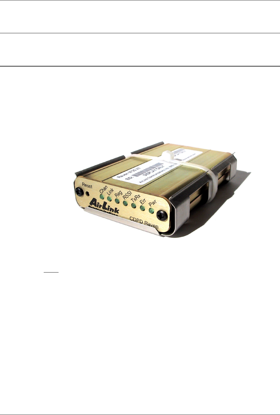
Raven Installation Raven GPRS User Guide Version 1.08
AirLink Communications, Inc. Page 52 September 29, 2003
8. Raven Installation
This section describes what is necessary to mount the Raven, connect the antenna
and connect the power.
8.1 Mounting the Raven
The Raven should be mounted in a position that allows easy routing and access for
the cables. There should be no binding or sharp corners in the cable routes. The
Raven should be mounted so that the LEDs on the front panel can be easily seen for
ease of operational verification.
The snap-in mounting bracket (part number 100-170-1006) is installed using #8 or
#10 screws. Press the Raven down firmly into the bracket and note that both sides
have locked into the groove on the Raven case.
Figure 1 - Raven Mounted in Mounting Bracket
Note: The tie-wrap is if the modem needs to be really secure, as in a vehicle or in
shipping. In stationary applications, as in a box that sits out in a pasture with a solar
cell, etc., the tie-wrap is not necessary.
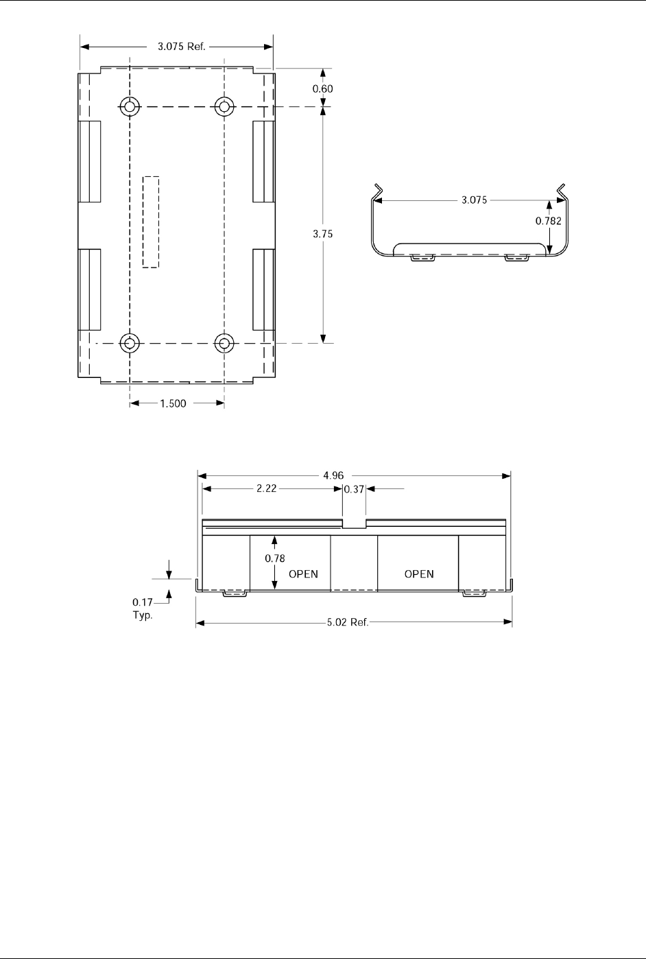
Raven Installation Raven GPRS User Guide Version 1.08
AirLink Communications, Inc. Page 53 September 29, 2003
Figure 2- Snap-in Mounting Bracket
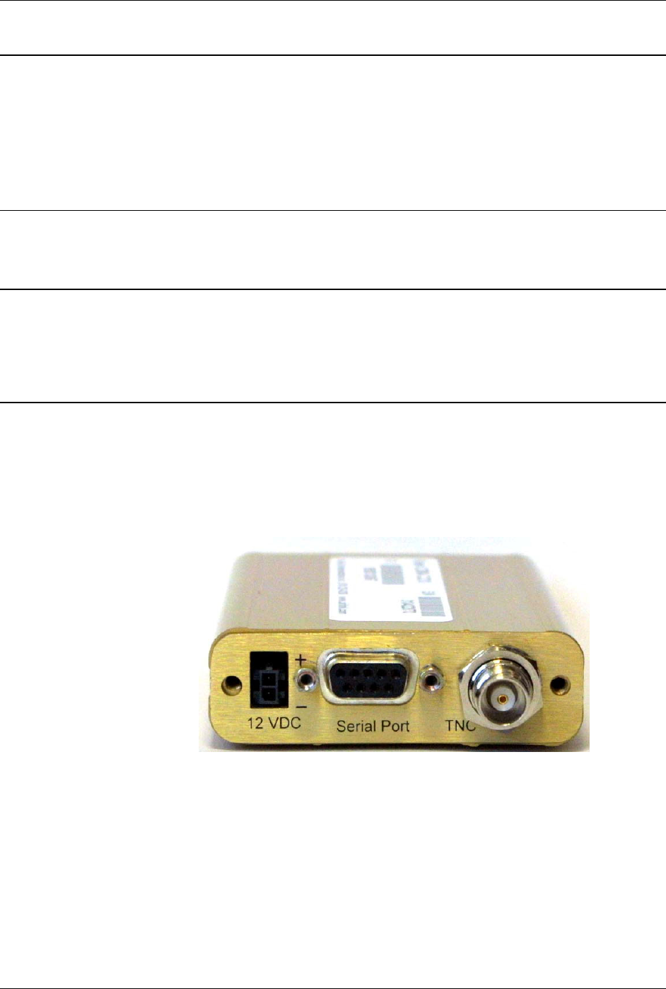
Raven Installation Raven GPRS User Guide Version 1.08
AirLink Communications, Inc. Page 54 September 29, 2003
8.2 Connecting the antenna
Install an appropriate external cellular antenna. Connect the antenna to the external
jack of the bulkhead jack adapter with an appropriate RF cable. Connect the Raven
antenna jack to the interior bulkhead jack with an appropriate RF cable.
Note if the antenna is mounted outdoors where there is a possibility of lightning or
static build up due to thunder storms passing by, then a lightning protection device
should be installed between the modem and the external antenna.
8.3 Connecting the serial cable
Connect the RTU/PLC meter serial port to the Raven serial port with a DB-9 male
connector.
8.4 Grounding the Raven Case
The exterior Raven case should be connected to the enclosure ground which should be
connected to the battery or power source negative terminal. This is best accomplished
with a grounding strap under one of the mounting bracket screws to the enclosure
grounding bar.
8.5 Connecting the power cable
The power cable positive lead should be connected to the battery or power source
positive terminal. The power cable negative lead should be connected to the battery
or power source negative terminal. The Raven has an internal polysilicon circuit
breaker that opens at 0.5 to 1.0 amps of current.
Insert the power connector into the Raven power receptacle.
Figure 3 - Raven Back Panel
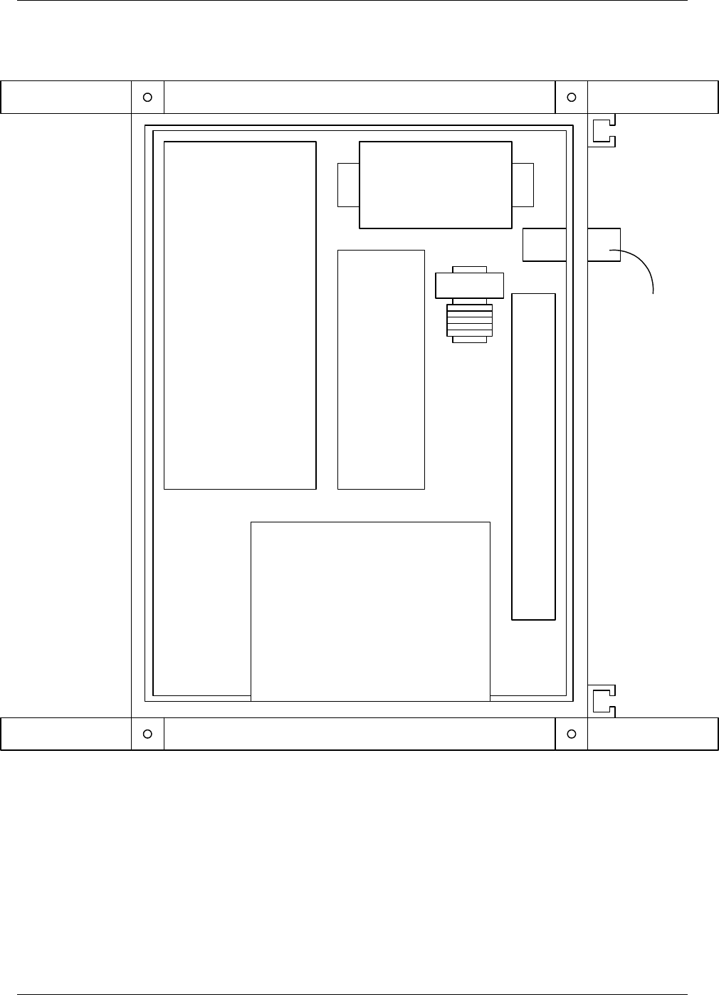
Raven Installation Raven GPRS User Guide Version 1.08
AirLink Communications, Inc. Page 55 September 29, 2003
Figure 4 Raven mounted in an enclosure with RTU
RTU
RAVEN
BATTERY
REGULATOR
TERMINAL BLOCK
POWER
DUCT
LIGHTNING
ARRESTOR
BATTERY
(BATTERY MOUNTED ON
1/2" THICK PLYWOOD.)
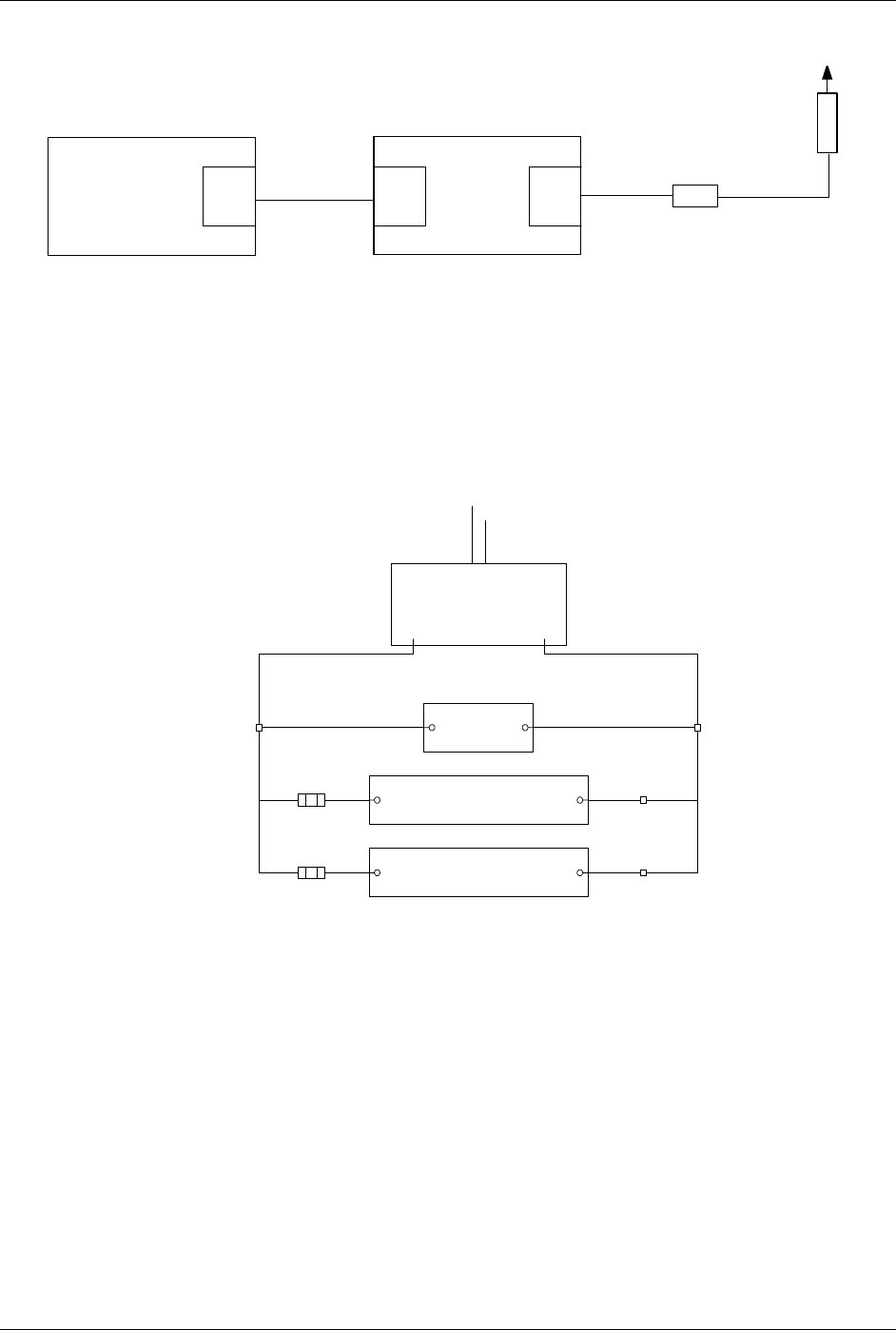
Raven Installation Raven GPRS User Guide Version 1.08
AirLink Communications, Inc. Page 56 September 29, 2003
Figure 5 - RTU to Raven setup
Figure 6 - Power Connections
COAX
CABLE
Lightening
Arrestor
(MOUNTED IN
PANEL)
Antenna
OUTSIDE
ANTENNA CABLE
RTU SERIAL
PORT
SERIAL
PORT TNC
Raven
CABLE
TO EXTERNAL
POWER SOURCE
(AC/DC)
POWER CONVERTER
VOLTAGE REGULATOR
12 VDC
12V
BATTERY
RTU
RAVEN
FUSES
1A
DC + DC -
+
+
GND
GND
+-

Raven GPRS Technical Specifications Raven GPRS User Guide Version 1.08
AirLink Communications, Inc. Page 57 September 29, 2003
9. Raven GPRS Technical Specifications
9.1 Physical Characteristics
Weight: < 1 lb.
Size: 3.3” wide x 2” high x 6.8" long
RF Antenna Connector: 50 Ohm TNC
Serial Interface: RS232 DB-9F
Rugged aluminum case
9.2 Power Specifications
Input Voltage: 10 VDC to 28 VDC
Idle Input Current: 40 mA at 12V
Typical Transmit/Receive: 130ma at 12VDC
Max Input Current 250 ma at 12 VDC
9.3 Environmental
Operating ranges: -30°C to +70°C*
(<10%duty cycle limit above 60 °C)
Humidity: 5%-95%Non-condensing
9.4 RF Features
Network: 1900/850 MHz GSM/GPRS
Transmit frequency: 1850-1910 MHz and 824-849 MHz
Receiver frequency: 1930-1990 MHz and 869-894 MHz
Transmit power range at antenna port: 1.0 W for 1900 MHz and
0.8W for 850 MHz
Transmitter can reduce output power when near a base station as per GSM
specifications
Receiver sensitivity: typical -107 dBm (2.2439% bit error rate)
Multislot Class 8
FCC certified (FCC Identifier GGL-R1902G)
Industry Canada certified (certification #4481A-R1902G)

Raven GPRS Technical Specifications Raven GPRS User Guide Version 1.08
AirLink Communications, Inc. Page 58 September 29, 2003
9.5 Status LED Display
Channel [Chan] LED
Flashing = Searching for a channel
On = Found a channel
Link LED
Off = No GPRS service
On = GPRS service is available on this channel
Winking off = Roaming
Winking on = GSM only signal, no GPRS.
Registration (REG) LED:
Off = No PPP link on GPRS network
On = PPP link is established on GPRS network and have an IP address.
RSSI LED
– Indicates signal strength. Signal strength is denoted as follows:
• < -100: RSSI LED off
• –99 to –90: Blink every 1200ms
• –89 to –80: Blink every 600ms
• –79 to –70: Blink every 300ms
• >= -69: RSSI LED on solid
Transmit Receive (Tx/Rx) LED:
Off = Idle
On = Transmitting/Receiving (on RF)
ERR LED
Currently unused
Power (PWR):
Off = Power off
On = Power on
9.6 Application Interface Features
RS232, 1200 bps to 115.2 kbps
AT Commands, PPP, SLIP, UDP, TCP