Sierra Wireless R1902G GSM 850/1900 Data Modems User Manual Raven GPRS User Guide
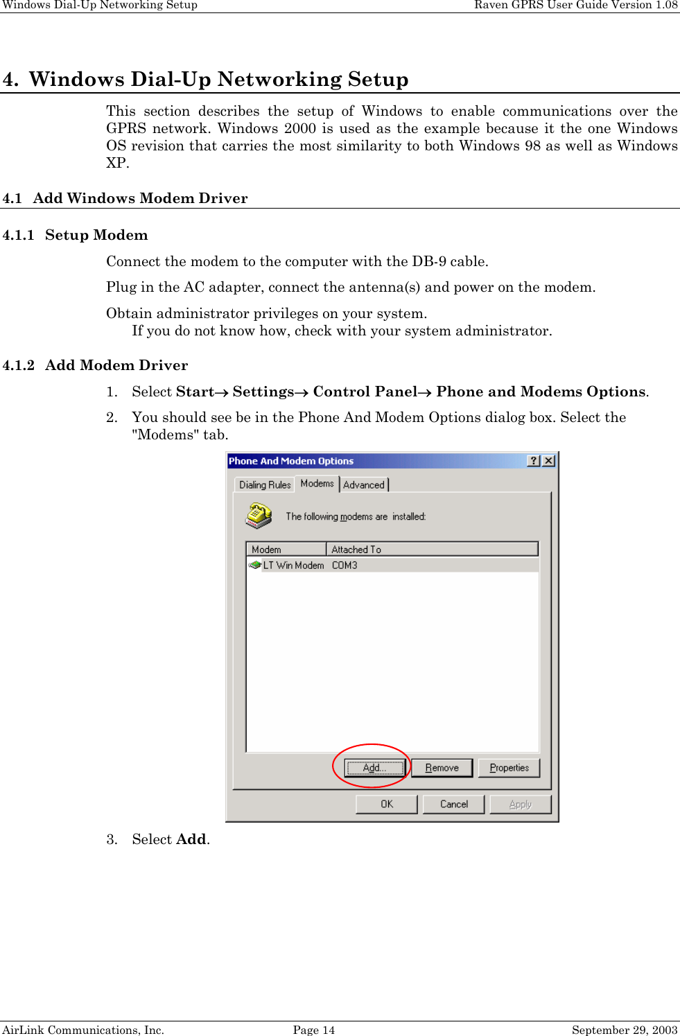
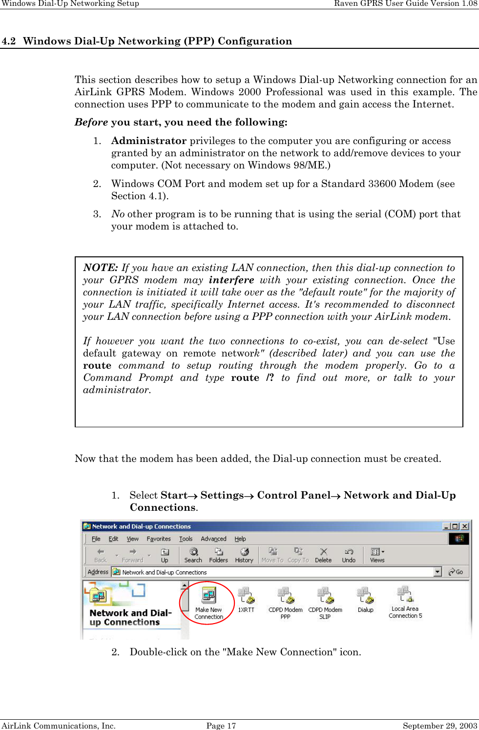
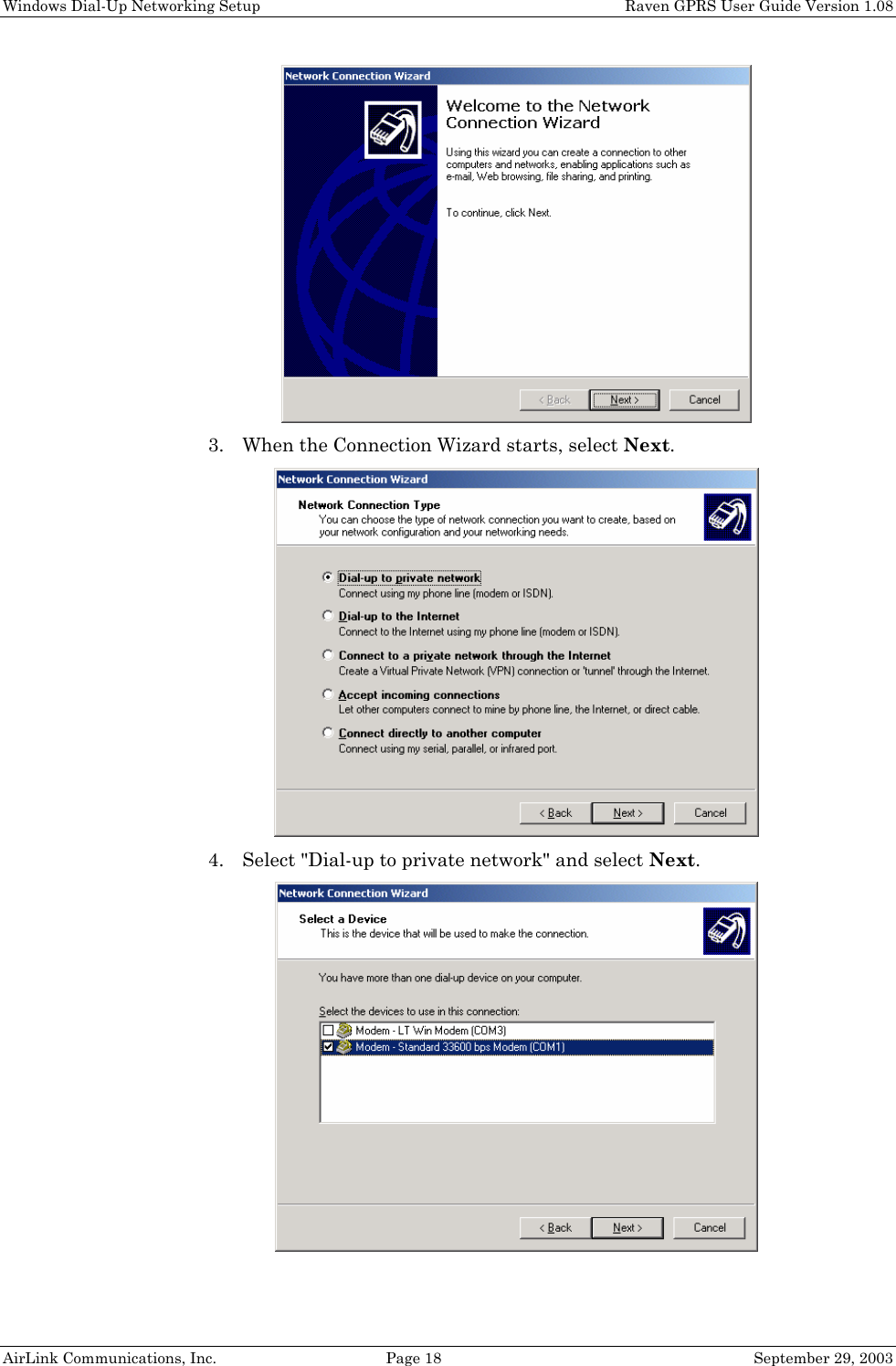
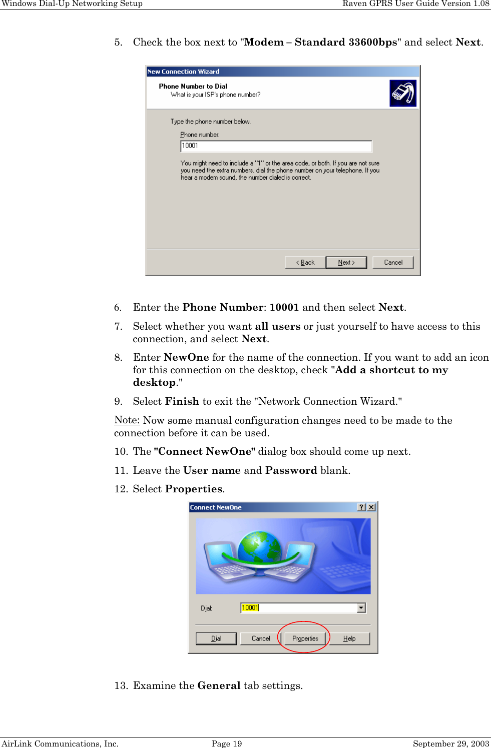
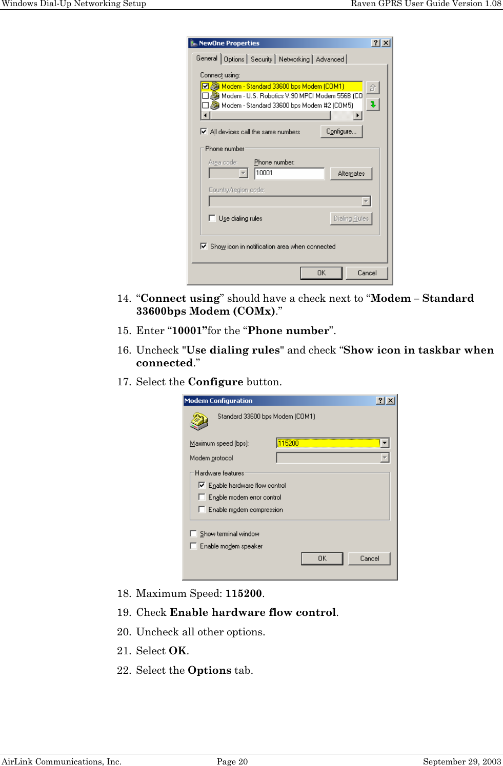
Sierra Wireless, Inc. GSM 850/1900 Data Modems Raven GPRS User Guide
Contents
- 1. Exhibit 8 User manual 3210
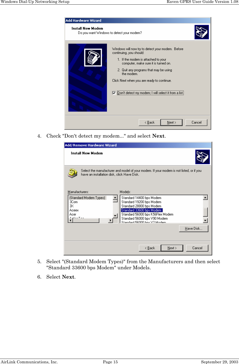
- 2. Exhibit 8 User manual 3310
- 3. Exhibit 8 User manual 3110
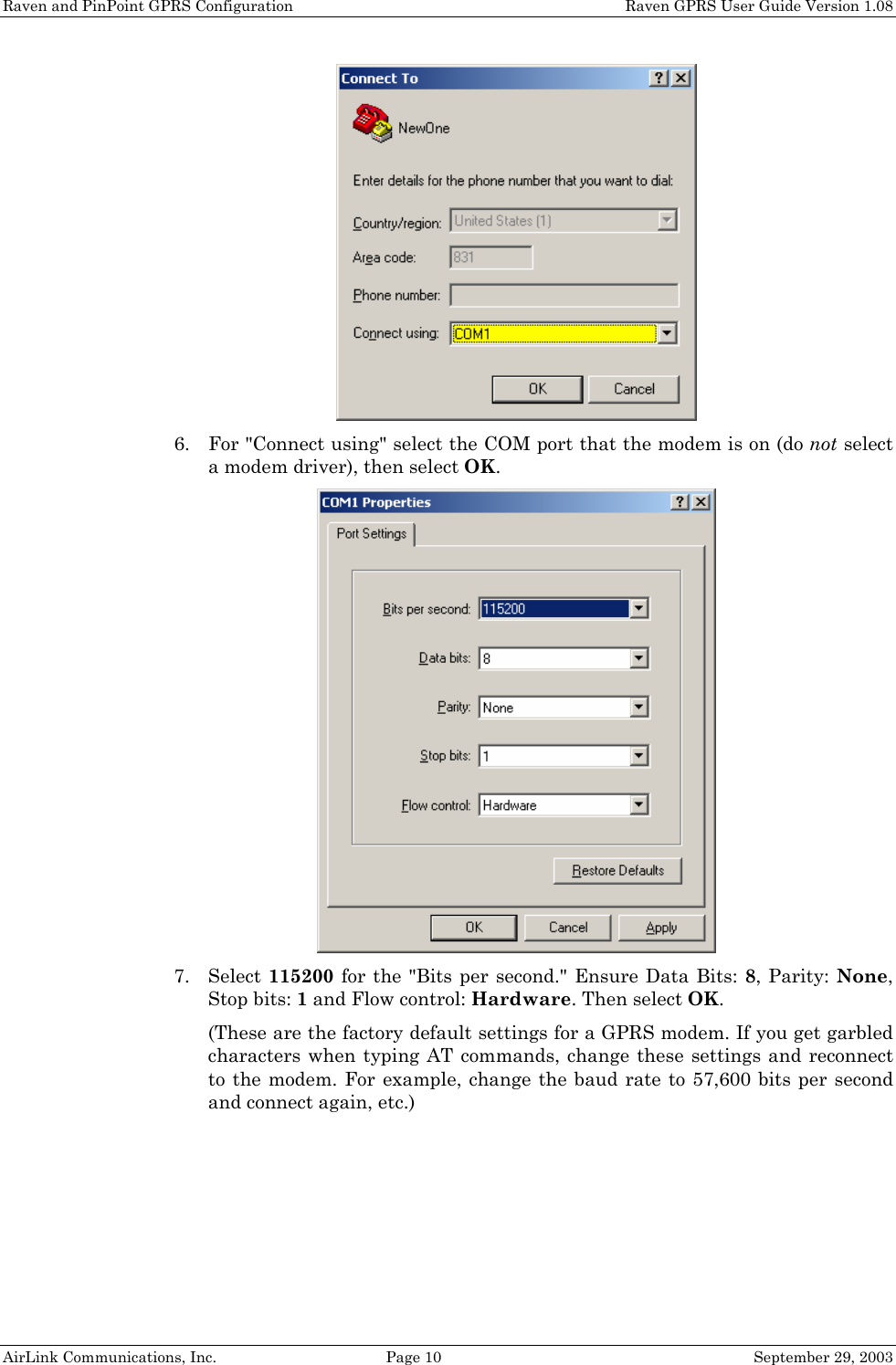
Exhibit 8 User manual 3210
![Raven GPRS User Guide Table of Contents 1. Introduction ..................................................................................... 5 1.1 Raven Product Overview ............................................................................... 6 2. Network Connection ...................................................................... 7 2.1 Internet (TCP/IP) Connections via GPRS .................................................... 7 2.2 Data Connections........................................................................................... 7 3. Raven and PinPoint GPRS Configuration ................................ 9 3.1 Local Configuration ....................................................................................... 9 3.2 Modem Activation........................................................................................ 11 3.2.1 SIM Check 12 3.2.2 PDP Context 12 3.3 Remote Configuration.................................................................................. 13 4. Windows Dial-Up Networking Setup ........................................ 14 4.1 Add Windows Modem Driver ...................................................................... 14 4.1.1 Setup Modem 14 4.1.2 Add Modem Driver 14 4.2 Windows Dial-Up Networking (PPP) Configuration ................................. 17 4.3 Making a GPRS Data Connection............................................................... 25 5. Dynamic IP Addresses ................................................................. 26 5.1 IPManager and Dynamic DNS Updates..................................................... 27 5.2 Using Names in the Modem, Domain Name Resolving............................. 27 6. Serial Communication Modes .................................................... 29 6.1 AT Mode ....................................................................................................... 30 6.2 PPP Mode ..................................................................................................... 30 6.3 PassThru Mode ............................................................................................ 31 6.4 UDP PAD Mode ........................................................................................... 31 6.4.1 UDP Auto Answer 32 6.4.2 Reliable UDP 32 6.4.3 Multicast UDP [Raven Only Feature] 33 6.5 TCP PAD Mode ............................................................................................ 33 6.6 TCP Auto Answer ........................................................................................ 34 6.7 Hybrid Modes............................................................................................... 34](https://usermanual.wiki/Sierra-Wireless/R1902G.Exhibit-8-User-manual-3210/User-Guide-371352-Page-5.png)
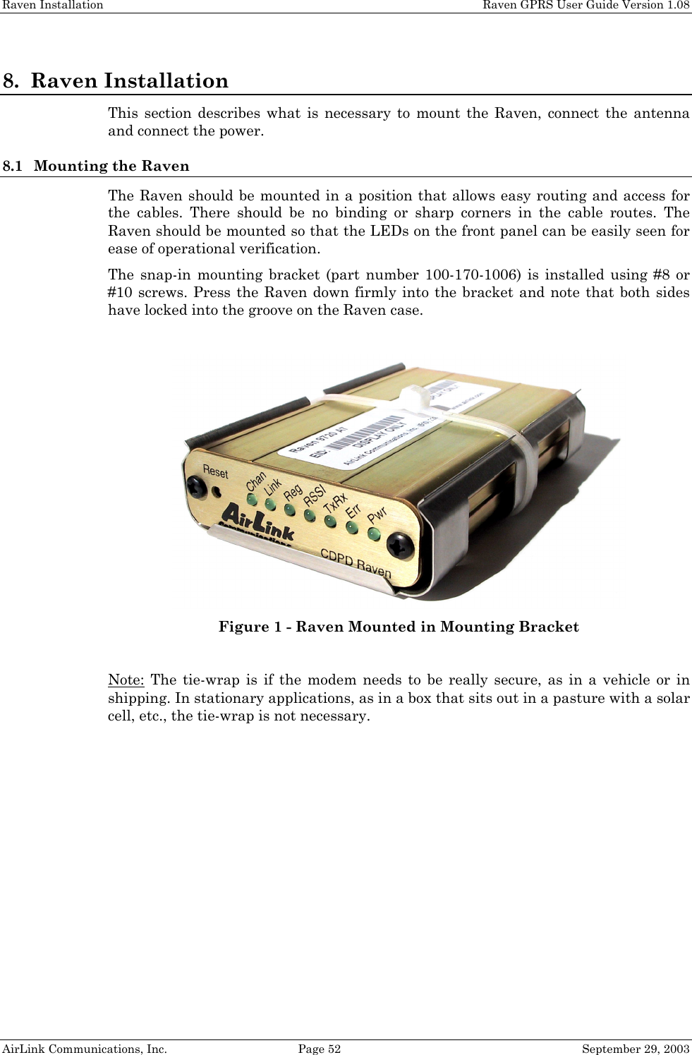
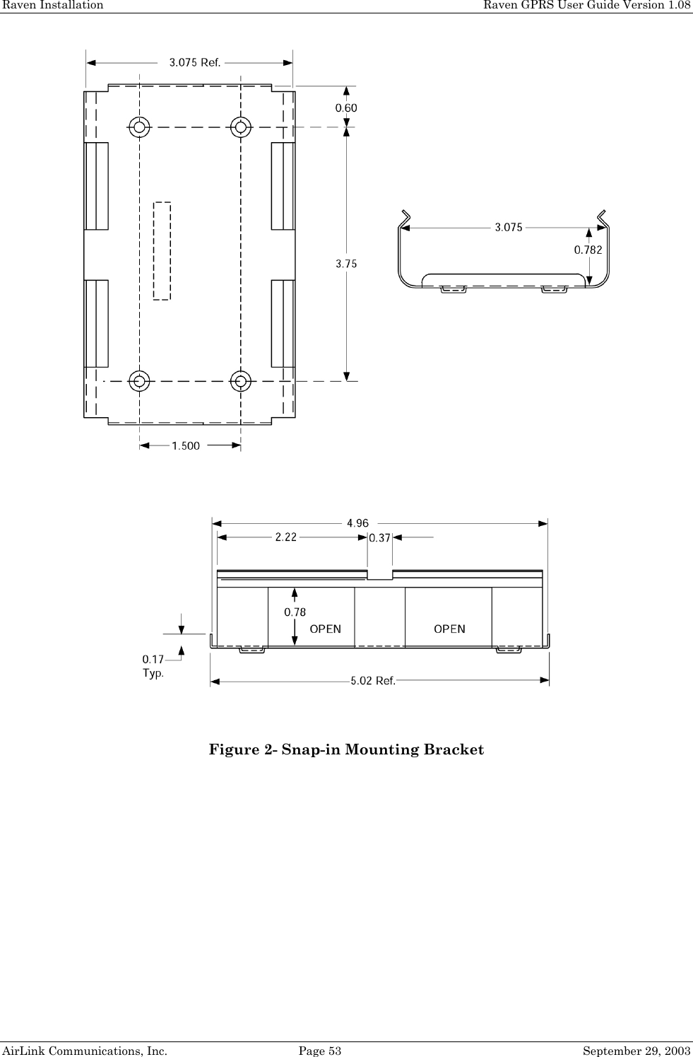
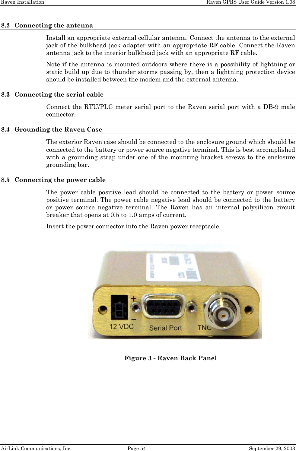
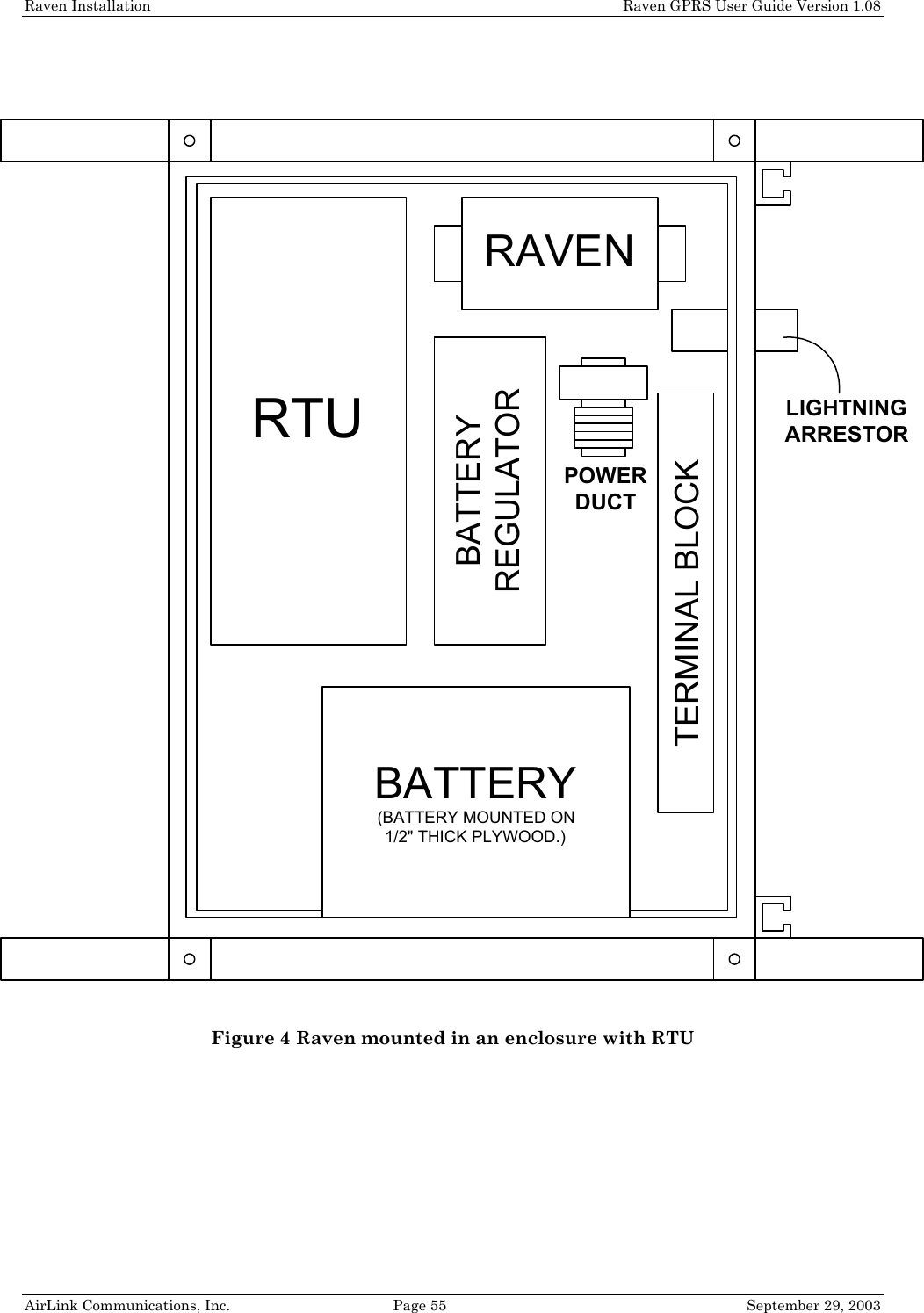
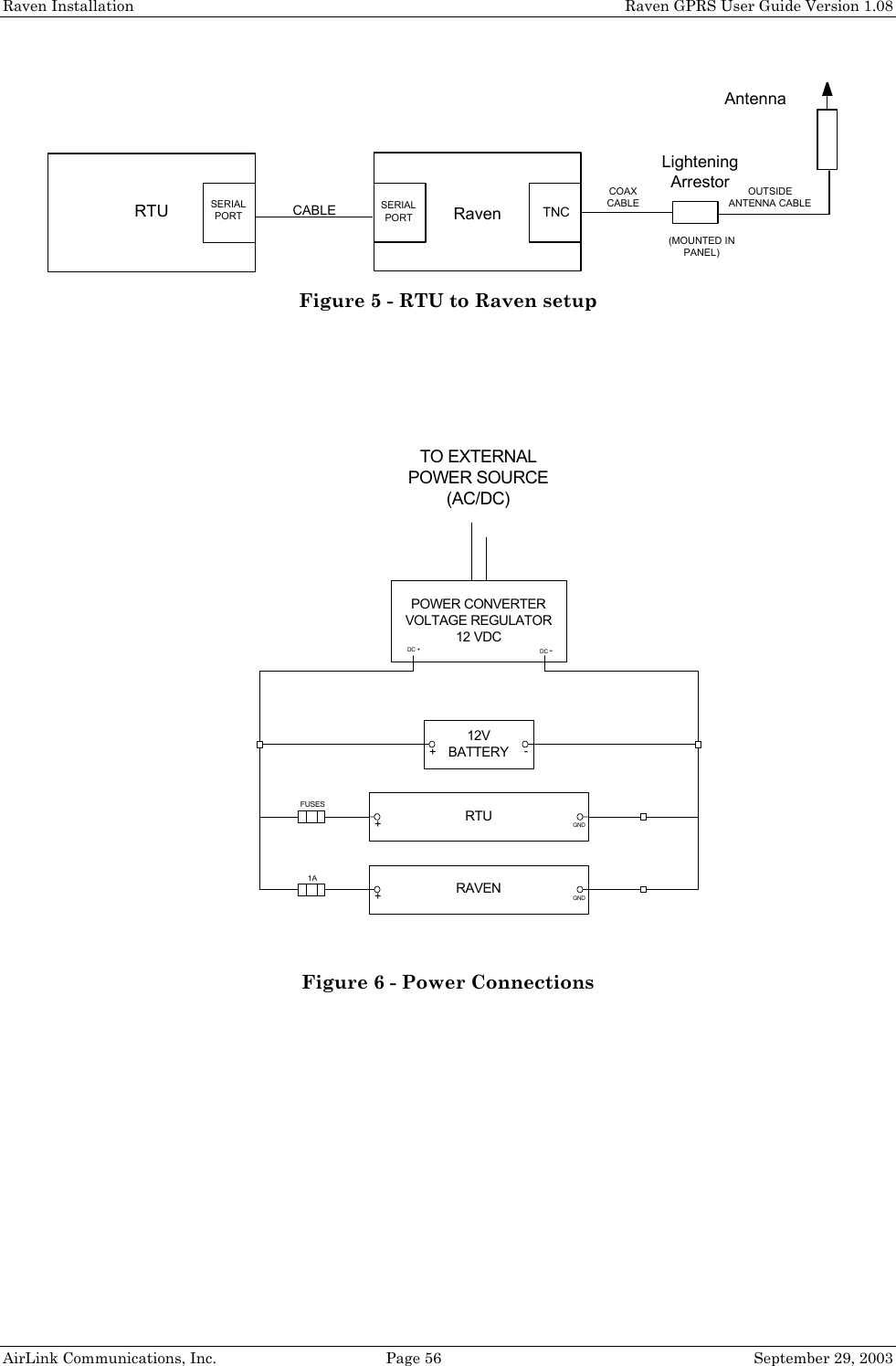
![6.8 SLIP Mode.................................................................................................... 35 6.9 Modbus/BSAP Configuration [Raven Only Feature] ................................. 35 6.9.1 Configuring the Polling Host Application Raven 35 6.9.2 Configuring the Remote Ravens 36 7. Using AT Commands .................................................................... 38 7.1 GPRS Specific AT Commands..................................................................... 39 7.2 Raven and PinPoint AT Command Reference............................................ 41 8. Raven Installation......................................................................... 52 8.1 Mounting the Raven .................................................................................... 52 8.2 Connecting the antenna .............................................................................. 54 8.3 Connecting the serial cable ......................................................................... 54 8.4 Grounding the Raven Case ......................................................................... 54 8.5 Connecting the power cable......................................................................... 54 9. Raven GPRS Technical Specifications..................................... 57 9.1 Physical Characteristics .............................................................................. 57 9.2 Power Specifications .................................................................................... 57 9.3 Environmental ............................................................................................. 57 9.4 RF Features ................................................................................................. 57 9.5 Status LED Display..................................................................................... 58 9.6 Application Interface Features ................................................................... 58](https://usermanual.wiki/Sierra-Wireless/R1902G.Exhibit-8-User-manual-3210/User-Guide-371352-Page-6.png)
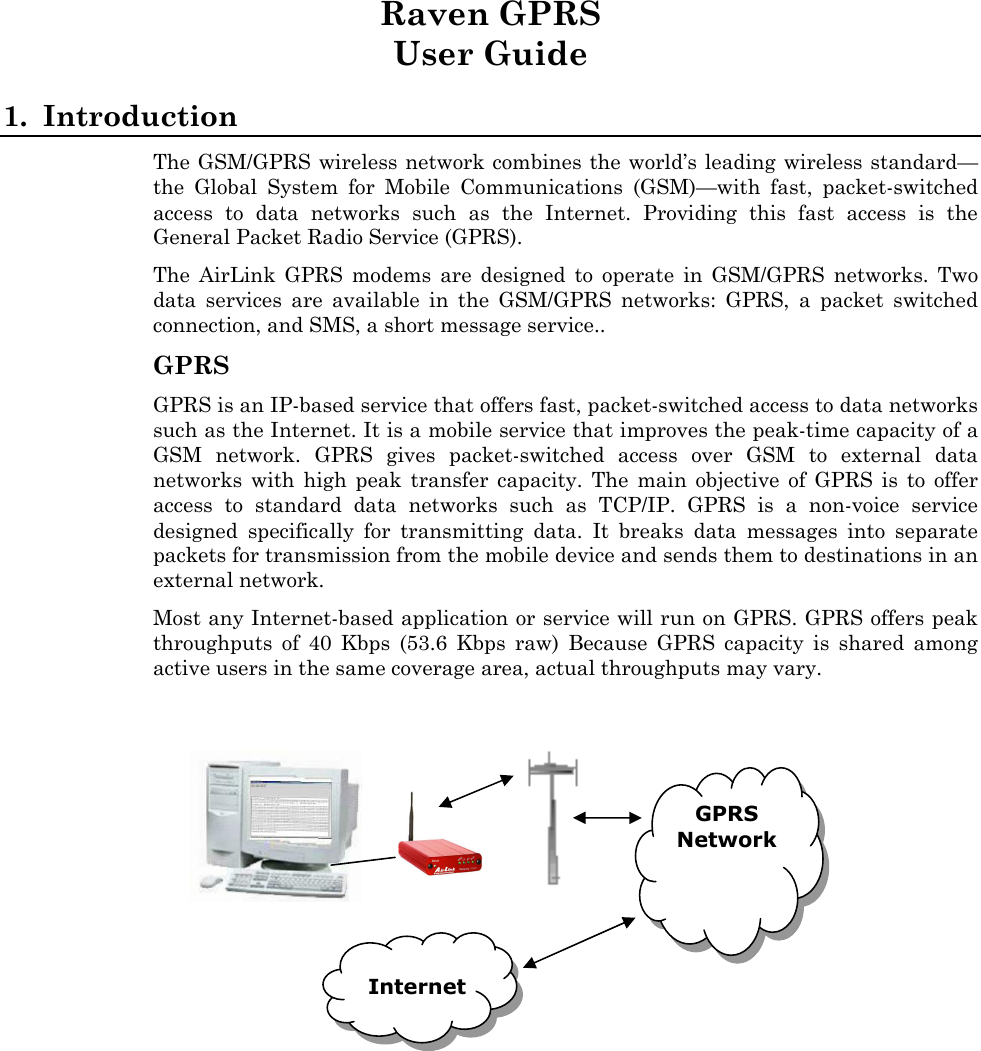
![Raven and PinPoint GPRS Configuration Raven GPRS User Guide Version 1.08 AirLink Communications, Inc. Page 11 September 29, 2003 8. Type AT followed by [Enter]. You should receive an "OK" in response. 9. Type ATI1 followed by [Enter]. This displays the modem firmware version and you should also see "AirLink Communications, Inc." in it which ensures you are talking to the AirLink modem. (If not, try changing COM ports.) Other AT commands may now be issued to the modem. See Section Using AT Commands for a list of AT commands 3.2 Modem Activation The GPRS modem is usually already set up to register online with a phone number, etc. pre-configured into it (by AirLink Communications, Inc.). When a modem is registered on the network and working, the lights will look like the following: Note that the RSSI light may be flashing or solid, showing the strength of the signal. Also the Tx/Rx (transmit/receive) light will flash as data is transferred to and from the modem on the network. AirLinkCommunications](https://usermanual.wiki/Sierra-Wireless/R1902G.Exhibit-8-User-manual-3210/User-Guide-371352-Page-13.png)
![Raven and PinPoint GPRS Configuration Raven GPRS User Guide Version 1.08 AirLink Communications, Inc. Page 12 September 29, 2003 If your modem lights look like the above when the modem is powered on, you do NOT need to configure the modem and may skip this section. If, however, the Reg light is not lit, your modem may need a SIM, or you may need to select the PDP context. • Connect up to configure the modem as in Section 3.1. • If you are unfamiliar with using AT commands, please review Section Using AT Commands first. 3.2.1 SIM Check You can check if a SIM [Subscriber Identity Module] is in the modem with the AT+CIMI? command. If a SIM is in the modem, you will see a response like the following: at+cimi? 310380006255650 OK The number is an abbreviated form of the IMSI [International Mobile Subscriber Identity] which is unique to each SIM. If there is no SIM, there will be a blank response like the following: at+cimi? OK 3.2.2 PDP Context Check if the PDP context is correct with the command: AT+CGDCONT? You should get a response like: at+cgdcont? 1,IP,proxy OK If you get a blank response, you need to set the PDP context. You need the APN [Access Point Name] which you can obtain from the carrier rep or from whomever you received the account. Most companies will be using a custom APN that allows them to communicate with all To set the PDP context: at+cgdcont=1,”IP”,”apn_obtained_from_carrier” at&w You only need to do this once. Henceforth, the modem will use this setting to attach to the GPRS network.](https://usermanual.wiki/Sierra-Wireless/R1902G.Exhibit-8-User-manual-3210/User-Guide-371352-Page-14.png)
![Raven and PinPoint GPRS Configuration Raven GPRS User Guide Version 1.08 AirLink Communications, Inc. Page 13 September 29, 2003 3.3 Remote Configuration Once the modem is online and registered, it can be contacted from a remote location via a setup that connects to the GPRS network using the same APN as the target modem. This can be accomplished by one of the following means: • A frame relay link to the carrier’s GPRS network • A VPN [Virtual Private Network] connection to the carrier’s GPRS network • Another GPRS modem where each of the above means is using the same APN as the target modem. Using a telnet application, a connection can be made to the modem and then AT commands can be issued to configure the modem, just as if a local connection were being made to the modem. (Note: If you wish to use Wireless ACE, please see the Important Note in Section 2.) 1. From a Command Prompt, type: telnet “Host Address” “Port Number” 2. For the "Host address" enter the IP address of the modem. (AT*NETIP? will reveal the current device IP address.) 3. For the "Port Number" use 2332. This is the default telnet port number for the GPRS modems. So it would look something like this: • telnet 192.168.100.23 2332 4. If the correct parameters have been entered, and the modem is currently online, you will get a "Password" prompt as shown below: AirLink AT command Interpreter Password ***** OK 5. Enter 12345 (default password) and press [Enter]. You will receive an OK. Now you may enter any AT commands to the modem as you would if you were doing a local connection to the modem. See Section Using AT Commands for AT commands and their options. You may want to set local echo in your terminal emulator to see what you type as you type. There is no remote echo function in the modem. Note: If the modem is configured to use a DDNS [Dynamic Directory Name Server], you could use a name in place of the IP address above, as in: telnet remote1.eairlink.com 2332](https://usermanual.wiki/Sierra-Wireless/R1902G.Exhibit-8-User-manual-3210/User-Guide-371352-Page-15.png)
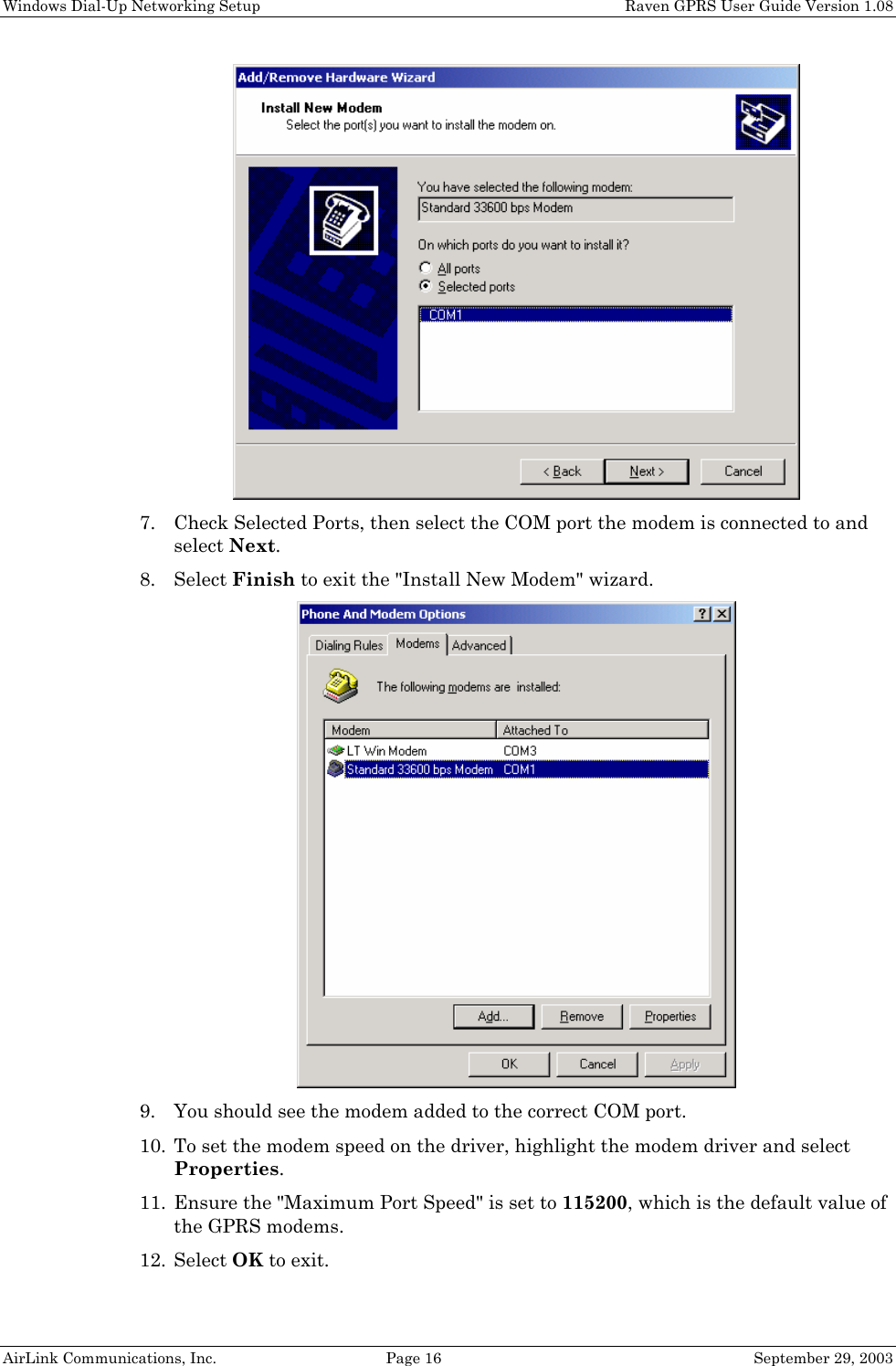
![Dynamic IP Addresses Raven GPRS User Guide Version 1.08 AirLink Communications, Inc. Page 27 September 29, 2003 5.1 IPManager and Dynamic DNS Updates The IPManager system provides a mechanism to implement a wireless Dynamic DNS service. If the IPManager settings are configured, the modem will send IP change notification messages to AirLink IPManager servers. These servers will then acknowledge the notifications and dynamically update a DNS server, thus allowing users to access a modem by domain name. The *IPMANAGER1 and *IPMANAGER2 settings can be set to either the domain name or IP address of a server to notify. The *MODEMNAME setting should be set to the name to prefix to the domain zone for which the IP Manager server is responsible. For example, if *MODEMNAME=mymodem and *IPMANAGER1 points to a server responsible for the eairlink.com domain zone, then the modem’s fully qualified domain name will be: mymodem.eairlink.com. To configure your AirLink modem to addressed by name, the modem needs to have 4 elements configured: 1. Modem name 2. Domain 3. IPManager IP Address 4. IPManager update interval The following illustrates a way to configure an AirLink modem to be addressed by name: at*modemname=mymodem at*domain=eairlink.com at*ipmanager1=eairlaink.com at*ipmgrupdate=60 [to update the DNS server at least hourly] 5.2 Using Names in the Modem, Domain Name Resolving The AirLink modems have an integrated DNS resolver, which uses the DNS entries specified by the *DNS1, *DNS2, and *DNSUSER settings. This allows the use of names in the AirLink modems instead of IP addresses. Both regular and reverse DNS lookups are supported. ATNSLOOKUP command will allow the lookup of an address or domain name. (e.g. atnslookup=www.microsoft.com will return the IP address for www.microsoft.com, while atnslookup=64.163.70.10 should return airlink.com). If a name resolution is performed on a name which is not fully qualified (i.e. contains no dotted portions), the value from *DOMAIN will be concatenated to the end. Typically the *DNS1 and *DNS2 values will be automatically filled in when a connection is negotiated with the carrier. The *DNSUSER value is provided to allow the user to specify a DNS server to check with before resorting to the carrier provided servers. If *DNSUSER is set to 0.0.0.0, it will be ignored and only the carrier DNS’s will be consulted. If it is set, the name server at the provided address will be queried first. If it doesn’t respond (within the timeout period, 10s) or can’t find the requested entry, the carrier DNS’s will then be queried. The special domain name “ppp-peer” will always resolve to the address to use to communicate with the PPP (or SLIP) host peer connected to the host port. If there is no PPP (or SLIP) peer (i.e. modem is not in PPP or SLIP mode), then “ppp-peer” will resolve to 0.0.0.0. If, for example, you wanted to report IP address changes to the](https://usermanual.wiki/Sierra-Wireless/R1902G.Exhibit-8-User-manual-3210/User-Guide-371352-Page-29.png)
![Serial Communication Modes Raven GPRS User Guide Version 1.08 AirLink Communications, Inc. Page 30 September 29, 2003 6.1 AT Mode AT commands are used to configure the modem, command it to do something, or query a setting. AT commands must always be terminated by <CR> (ASCII character 0x0D). If E=1 (Echo On), the AT command (including the terminating <CR>) will be output before any responses defined in the next section. Response Framing Two settings affect the format of AT command output: V (Verbose) and Q (Quiet). If Q=1 (Quiet On), no result codes are output whatsoever, so there is no response generated by a (non query) command. If Q=0 (Quiet Off), result codes are output. The format of this output if then affected by the Verbose setting. If Quiet mode is off, the result code is affected as follows: For V=1 (Verbose mode), the textual result code is surrounded by <CR><LF> and any AT query response is also surrounded by <CR><LF>; for V=0, (Terse mode), a numeric result code is output with a single trailing <CR> (no <LF> is output), while any AT query response is followed by <CR><LF> (there is no preceding output). For example, possible output to the AT command “AT<CR>” (assuming quiet mode is not on) is: 0<CR> - if V=0 <CR><LF>OK<CR><LF> - if V=1 6.2 PPP Mode In PPP mode, the modem acts as a PPP server, providing an IP address, and DNS servers (if available) to the Host. PPP mode is entered from the AT mode by using any of the following commands: AT\APPP<CR> ATDT10.0.0.1<CR> ATDT10001<CR> ATD#19788<CR> CLIENT<CR> In response to any of the preceding commands, the modem will respond with CONNECT<CR><lf> and is ready for the host to begin PPP negotiations. The IP received by the host in the resulting negotiation will either be a private (non-routable) IP or a public (network-routable) IP provided by the network, depending on the settings of *USEPRIVATEIP [S300]. If *USEPRIVATEIP =1, the value of the private IP an be determined beforehand by querying S110. The private IP to be used](https://usermanual.wiki/Sierra-Wireless/R1902G.Exhibit-8-User-manual-3210/User-Guide-371352-Page-32.png)
![Serial Communication Modes Raven GPRS User Guide Version 1.08 AirLink Communications, Inc. Page 32 September 29, 2003 - The modem is in AT mode [not in a current UDP or TCP session] UDP packet assembly is affected by the values of S50 (PAD Forwarding Timeout) and S51 (PAD Forwarding Character). Data received in the serial buffer will be transmitted when the idle inter-character timeout specified in S50 (in tenths of seconds) occurs or when a character is received that matches S51 (if non-zero). The host can exit UDP mode by deactivating DTR (if S211=0 or &D2) or by issuing the +++ escape sequence. 6.4.1 UDP Auto Answer UDP auto answer (previously called UDP half-open) is set with S82=2. When set, the modem will automatically establish a UDP session to the source IP address and port of the UDP packet received. The modem will remain “locked” to this one remote IP/port until no data is sent or received for the time interval defined in the UDP auto answer timeout (S83). During this session, packets from other IP/port addresses will be rejected, unless *UALL is set. Whether or not an incoming packet will cause the modem to enter a UDP session is always dependent on the S53 and AIP settings. When idle, after the timeout has occurred, the modem is in AT command mode on the serial port, and any valid AT command may be entered during this time. The Normal UDP Mode (MD3) can be combined with UDP auto answer to cause the incoming serial data to be sent in UDP packets (instead of being treated as AT commands), while allowing sessions to be established from different UDP sources. A UDP session will be initiated either by incoming serial data or by an incoming UDP packet. The session, started by either method, will be terminated when no data has been sent or received for the S82 period. Once the session terminates, another may be initiated by either means. When the session is initiated by serial data, the new session will be established using the destination address specified in S53. The S53 setting can be changed if the connect to last UDP setting (*UDPLAST=1) is set. The address in S53 will be updated to reflect the address of the last session initiated by an incoming UDP packet. So that when new data is received over the host serial port while in the idle state, a session will be re-established with the last address. (This behavior is the same as the previous Hybrid2 (MD6) mode). Note that TCP auto answer (S0=[1|2]) may also be set simultaneously with UDP auto answer. Then, when in the idle state, the modem will accept either a TCP or UDP incoming packet, and enter a TCP or UDP session as appropriate. 6.4.2 Reliable UDP Reliable UDP adds a simple protocol on top of UDP to provide reliable deliver of data. When data is received from the host serial port, a 2 byte header is added to the data, containing a message type and a sequence number. The modem will continue to send this data (buffering any received data in the meantime) until it receives an acknowledgement with this sequence number. If an acknowledgement is not received within the timeout period (specified in S7), the data will be retransmitted. This will continue until an acknowledgement is received or the modem is reset. Likewise any UDP packets received by the modem are expected to have this simple header. The modem will issue an acknowledgement for any valid packets which are received. Configure the modem as for a normal UDP session. Set the Startup Mode Default to 3, and the UDP Mode Default to 7 [ATMD73]. If using two modems, configure](https://usermanual.wiki/Sierra-Wireless/R1902G.Exhibit-8-User-manual-3210/User-Guide-371352-Page-34.png)
![Serial Communication Modes Raven GPRS User Guide Version 1.08 AirLink Communications, Inc. Page 33 September 29, 2003 the Destination IP and Port in each to point to each other. Serial data will then be sent reliably between the two Although it adds reliability, the simple implementation of the Reliable UDP mode in the modem does not check for duplicate packets. 6.4.3 Multicast UDP [Raven Only Feature] Multicast UDP results in any data received from the host serial port being sent to all the clients in the Modbus list. The remote port number is taken from S53. To avoid flooding the network, the packets are sent to each client with a 20ms pause in between. The receipt of UDP packets works as in normal UDP mode (i.e. bound by the value S53 and/or AIP). Since it may take a while to transmit the data to all hosts (especially if all 20 Modbus entries are used and name resolutions are required), new data received from the host port is buffered until current transmissions to all hosts are finished. Enter the list of target IPs in the Modbus IP list. The index numbers in the IP list aren't used. Configure the Raven as for a normal UDP session. Set the Startup Mode Default to 3, and the UDP Mode Default to 8 [ATMD83]. Configure the Destination port to match the device port of the remote modems. 6.5 TCP PAD Mode When the modem is in a TCP session, all characters received on the serial port are assembled into TCP packets and sent to the mode’s remote IP address/port, and any packets received from the remote end of the TCP connection are disassembled and dumped onto the serial line. Note that DTR needs to be asserted (or S211=1 or &D0) by the host before a TCP session can be entered. A TCP connection is established by one of the following methods: • Using the Dial TCP (DT) AT command (as in, ATDT192.168.3.23/3456) • TCP auto answer is enabled (S0=1|2), a TCP connection request is received, and the modem is not in a data session. • Data is received on the serial port and - The Startup Mode Default (MD) is 4 (auto TCP) - The remote TCP destination, as defined in S53, successfully responds to the TCP connection request. The value of S7 (TCP Connection Timeout) specifies the number of seconds to wait, after initiating a TCP connection attempt, for a successful connection to be established. If the connection has not been successfully established before the timeout occurs, ERROR/BUSY is returned. TCP packet assembly is affected by the values of S50 (PAD Forwarding Timeout) and S51 (PAD Forwarding Character). Data received in the serial buffer will be transmitted when the idle inter-character timeout specified in S50 (in tenths of seconds) occurs or when a character is received that matches S51 (if non-zero).](https://usermanual.wiki/Sierra-Wireless/R1902G.Exhibit-8-User-manual-3210/User-Guide-371352-Page-35.png)
![Serial Communication Modes Raven GPRS User Guide Version 1.08 AirLink Communications, Inc. Page 34 September 29, 2003 The TCP session will be terminated if no data is transmitted or received for the time interval specified in TCPT and TCPS. TCPT is the number of minutes [TCPS=0] or seconds [TCPS=1] used for this idle timeout. TCPT should never be 0 when using the TCP mode. A broken TCP session can result in the modem being left with a TCP half-open connection that can only be terminated with a reset. The host can also terminate a TCP session by deactivating DTR (if S211=0 or &D2) or issuing the +++ escape sequence. Note that DTR needs to be asserted (or S211=1 or &D0) by the host before a TCP session can be started. 6.6 TCP Auto Answer TCP auto answer (S0=1|2) also allows a TCP connection request to be “answered” when the modem is idle, not in a data session. Note that DTR needs to be asserted (or S211=1 or &D0) by the host before a TCP session can be entered. The TCP connection request’s destination port has to match the modem’s device port. Note that UDP auto answer may also be set simultaneously with TCP auto answer. Then, when in the idle state, the modem will accept either a TCP connection request or UDP incoming packet, and enter a TCP or UDP session as appropriate. 6.7 Hybrid Modes Some previous hybrid modes (MD=5, 6) are no longer implemented as special, unique modes. Now that UDP auto answer (UDP Half-open, S82=2) can be enabled in conjunction with UDP PAD mode (MD3), effectively this is the same as MD5 and MD6 previously accomplished. Setting MD5 and MD6 are still supported, but not recommended, since all they do is set several settings as described below. The settings to accomplish hybrid modes: AT Setting Hybrid (MD5) Hybrid2 (MD6) MD 3 3 S82 2 2 S0 1 1 *UDPLAST 0 1](https://usermanual.wiki/Sierra-Wireless/R1902G.Exhibit-8-User-manual-3210/User-Guide-371352-Page-36.png)
![Serial Communication Modes Raven GPRS User Guide Version 1.08 AirLink Communications, Inc. Page 35 September 29, 2003 6.8 SLIP Mode SLIP mode is entered be using the “AT\ASLIP” command. As in PPP Mode, the IP address that the host assumes is affected by the setting of S300. SLIP does not negotiate the IP with the host, so before making a SLIP connection, the host SLIP driver must be configured to use the IP specified by querying S110. The host can exit SLIP mode by deactivating DTR (if S211=0 or &D2) or issuing the +++ AT escape sequence. Note that DTR needs to be asserted (or S211=1 or &D0) by the host before SLIP mode can be entered. 6.9 Modbus/BSAP Configuration [Raven Only Feature] Modbus, BSAP, and Modbus variations are communications protocols that are widely used in telemetry. They were designed to be used in a radio environment where packets are broadcast to a group of remote units. Each Modbus packet contains an ID so that only the one remote unit, whose ID matches the ID in the packet, will respond to the host. The ID is used to address a specific remote. When Ravens are used in place of radios, there is a Raven connected to the host computer and a Raven connected to each remote unit. Packets transmitted from the host need to contain the IP address of the specific remote unit whose ID matches the ID in the packet from the host computer. The Modbus/BSAP feature adds the capability for a list of IP addresses or names, and matching remote IDs to be entered into the host Raven. When the host computer sends a poll request, the ID is matched to the corresponding IP address and a UDP packet is assembled using this IP address. The complete packet from the host is then encapsulated in this UDP packet and transmitted to the remote unit. The remote units operate in normal UDP mode and their data is sent to the host. 6.9.1 Configuring the Polling Host Application Raven Set the S53 Port to match whatever port number is being used on all the remote modems. For example, if the remote Ravens’ S110 port number being used is "12345", then the Modbus host Raven’s S53 port should be set to “12345”. ATMD13 for Modbus ASCII ATMD23 for Modbus RTU (Binary) ATMD33 for BSAP ATMD63 Variable Modbus [where you set up the individual parameters] Enter the list of ID/Local addresses and their associated remote IP addresses or names as follows: The ID/Local address and IP or name is entered using the ATMLIST or ATMLISTX commands. ATMLIST allows the ID to be entered in decimal, while ATMLISTX allows the ID to be entered in hex. For example, if a remote's IP address is 123.456.133.45 or name is remote1, and its ID/Local address is 27, you can enter: ATMLIST27=123.456.133.45 If you want to enter the ID is hex:](https://usermanual.wiki/Sierra-Wireless/R1902G.Exhibit-8-User-manual-3210/User-Guide-371352-Page-37.png)
![Serial Communication Modes Raven GPRS User Guide Version 1.08 AirLink Communications, Inc. Page 36 September 29, 2003 ATMLISTX1B=123.456.133.45 Continue until all the remotes are entered. There can be a total of 20 remote ID/Local addresses entered into a Raven. Note a special build Raven Modbus Host version is available that allows up to 100 entries in the list. Remember to save the entries with AT&W. If Using Dynamic IPs The host Raven should be configured to report its current IP to a DDNS server so the remote Ravens can use DDNS to obtain the host Raven’s IP. The remote Ravens can then send their current IPs to the host Raven which will update the Modbus IP list by matching the modem names. Enter names into the IP list as follows: ATMLIST27=remote1 or ATMLISTX1B=remote1 Continue until all the remotes are entered. There can be a total of 20 remote ID/Local addresses entered into a Raven. Note a special build Raven Modbus Host version is available that allows up to 100 entries in the list. Remember to save the entries with AT&W. 6.9.2 Configuring the Remote Ravens The remote Ravens connected to the RTUs being polled, need to be set up for normal UDP operation. ATMD3 for Normal UDP operation For Static IPs Set ATS53= IP address/port number of the Raven connected to the Polling Host. If the polling host Raven’s IP and port are 123.456.133.11 and 12345, set as follows: ATS53=123.456.133.11/12345 ATS53=home1/12345 If Using Dynamic IPs Set ATS53= name/port number of the host Raven. If the polling host Raven’s *MODEMNAME and Device Port are home1 and 12345, set as follows: ATS53=home1/12345 The remote Ravens need to be configured to update the host Raven with their current IPs. Set up *IPMANAGER[1|2] to point to the host Raven: *IPMANAGER[1|2]=home1 where home1 = *MODEMNAME in the host Raven. *DOMAIN should match the domain of the host Raven. For example, if the DDNS being used is eairlink.com, then *DOMAIN=eairlink.com. And the fully qualified domain name the remote Raven would query is home1.eairlink.com.](https://usermanual.wiki/Sierra-Wireless/R1902G.Exhibit-8-User-manual-3210/User-Guide-371352-Page-38.png)
![Serial Communication Modes Raven GPRS User Guide Version 1.08 AirLink Communications, Inc. Page 37 September 29, 2003 A new IP update will be sent anytime the remote Raven detects that its IP has changed. A periodic update is a redundant process that guarantees the host Raven will be updated in the event the host Raven loses its IP list for any reason or the remote Raven’s IP is changed or dropped without notification to the remote Raven. Configure the frequency the IP update will be occur. AT*IPMGRUPDATE[1|2]=n where n = minutes [0-255] Other parameters may need to be changed, but this is dependent on the RTU type being used. Remember to save your configuration with AT&W.](https://usermanual.wiki/Sierra-Wireless/R1902G.Exhibit-8-User-manual-3210/User-Guide-371352-Page-39.png)
![Using AT Commands Raven GPRS User Guide Version 1.08 AirLink Communications, Inc. Page 39 September 29, 2003 7.1 GPRS Specific AT Commands These AT commands are specific to the GPRS devices and networks. Command Description +CGDCONT=cid, PDP_type, APN [?] Define the PDP context. Must be defined before a connection can be made to the GRPS network. Needs to be configured only once, the parameters are saved and used each time a connection is made to the GPRS network. cid = PDP Context Identifier: numeric parameter that specifies a PDP context definition. PDP_type = Packet Data Protocol type = “IP” APN = Access Point Name a logical name that is used to select the GGSN or the external packet data network. Can only be what’s on the SIM AT+CGDCONT = 1,”IP”,”proxy” AT+CGDCONT = 1,”IP”,”public” +COPS? Returns the currently selected network operator. AT+COPS? AT&T Wireless OK +ICCID? Returns the 20 digit SIM ID AT+ICCID? 89310380101024729959 OK](https://usermanual.wiki/Sierra-Wireless/R1902G.Exhibit-8-User-manual-3210/User-Guide-371352-Page-41.png)
![Raven and PinPoint AT Command Reference Raven GPRS User Guide Version 1.08 AirLink Communications, Inc. Page 41 September 29, 2003 7.2 Raven and PinPoint AT Command Reference Command Description +++ AT Escape sequence (not preceded by AT). If modem is in a data mode, this sequence causes the modem to re-enter AT command mode. There must be 1 second of idle time on the serial port before and after the sequence. Note that the “+” is ASCII character 0x2B. NOTE: The detection of this sequence is disabled if DAE=1 A/ Re-execute last command. AIP=n [?] n = 0: Allow only the IP specified in S53 to connect when UDP auto answer is enabled (S82=2). n = 1: Allow any incoming IP to connect when UDP auto answer is enabled (S82=2). Always subject to any Friends filters that may be defined](https://usermanual.wiki/Sierra-Wireless/R1902G.Exhibit-8-User-manual-3210/User-Guide-371352-Page-43.png)
![Raven and PinPoint AT Command Reference Raven GPRS User Guide Version 1.08 AirLink Communications, Inc. Page 42 September 29, 2003 Command Description D[method][d.d.d.d][/ppppp] or D[method][[@]name][/ppppp] Dial a connection to a remote IP and Port using either UDP, TCP, or Telnet. method = P – Establish a UDP connection T – Establish a TCP connection N – Establish a Telnet connection d.d.d.d = IP address to establish connection to name = domain name to establish connection to ppppp = IP port to establish connection to Examples: ATD – Dial (establish) default connection per S53 ATDPnnn.nnn.nnn.nnn[/ppppp] - Dial (establish) UDP session to the specified IP address/port. If the method, IP address, or port is omitted, the values from S53 are used. If a telnet connection is requested (N) and the port is not supplied, port 23 will be used instead of the value from S53. Several special dialing numbers exist to make it easy to establish a PPP or SLIP connection with the modem. ATD#19788 or ATDT#19788 will establish a PPP connection (see \APPP) and ATDT#7547 will establish a SLIP connection (see \ASLIP). If a domain name is specified, the ‘@’ symbol can be used to explicitly indicate the start of the name. For example, if “ATDPHONY” is issued, this will be interpreted as dial a UDP connection to ”HONY”. To dial using the default method to host “PHONY”, one would issue “ATD@PHONY”. To end the connection, issue the +++ escape sequence or drop the DTR line (if Ignore DTR S211=0 or &D2) NOTE: The source port of the session is the Device Port (set by S110 or *DPORT) DAE=n [?] Disable AT Escape Sequence detection n = 0: Enable +++ AT escape sequence detection. n = 1: Disable +++ AT escape sequence detection. En Toggle AT command echo mode. n = 0: Echo Off n = 1: Echo On. FM=n [?] Friends Mode – Only allow specified IPs to access the modem n = 0: Disable Friends mode n = 1: Enable Friends mode – Only packets from friends will be accepted (see below); packets from other IP addresses are ignored.](https://usermanual.wiki/Sierra-Wireless/R1902G.Exhibit-8-User-manual-3210/User-Guide-371352-Page-44.png)
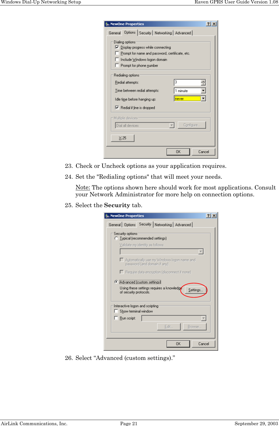
![Raven and PinPoint AT Command Reference Raven GPRS User Guide Version 1.08 AirLink Communications, Inc. Page 43 September 29, 2003 Command Description Fn=d.d.d.d [?] Friends mode IP address n = Friends list index [1 – 10] d.d.d.d = IP address to be allowed to access the modem 255 = allow any number 0-255 Example: 166.129.2.255 allows access by all IPs in the range 166.129.2.0—166.129.2.255. H This command does nothing but does not cause an error either. HOR=n [?] Half-Open Response – In UDP auto answer (half-open) mode: n = 0: No response codes when UDP session is initiated n = 1: RING CONNECT response codes sent out serial link before the data from the first UDP packet. Note: Quiet Mode must be Off. I[0] Returns the product name. I1 Returns AirLink modem’s firmware version, hardware ID, and copyright. I2 Returns the OEM Modem’s firmware version and relevant hardware ID I3 Returns the OEM Modem’s unique ID M This command does nothing but does not cause an error either. MDhh [?] Set or query the modem's default power-up mode hh (hex byte) = When the modem is power-cycled, it may enter the mode specified by this command after 5 seconds. On startup, typing ATMD0 within 5 seconds changes the mode to normal. 00 – normal (AT command) mode 01 – SLIP mode 02 – PPP mode 03 – UDP mode (address/port is in S53) 04 – TCP mode (address/port is in S53) [Also see Modbus Modes for Ravens] OPRG=n [?] Enables/disables over-the-air firmware upgrading of the modem. n = 0: Disables over-the-air programming. n = 1: Enables over-the-air programming. PINGd.d.d.d[,n] PING domain_name[,n] Ping the specified IP address. Sends a single ping, returns either OK or ERROR depending on result. Times out in 10 seconds. If n is provided, it specifies the amount of data to send with the ping. If n is not provided, the default, 50 bytes is used.](https://usermanual.wiki/Sierra-Wireless/R1902G.Exhibit-8-User-manual-3210/User-Guide-371352-Page-45.png)
![Raven and PinPoint AT Command Reference Raven GPRS User Guide Version 1.08 AirLink Communications, Inc. Page 44 September 29, 2003 Command Description Qn [?] Set or query the AT quiet-mode setting. If quiet mode is set, there will be no responses to AT commands except for data queried. n = 0: Off (Default) n = 1: Quiet-mode on. S0=n [?] This register determines how a modem responds to an incoming TCP connection request. The modem remains in AT Command mode until a connection request is received. DTR must be asserted or (or S211=1 or &D0) must be set for a successful TCP connection. The modem will send a “RING” string to the host. A “CONNECT” sent to the host indicates acknowledgement of the connection request and the TCP session is established. n = 0: Off (Default) n = 1: On n = 2: Use Telnet server mode on TCP connections S7=n [?] Specifies the number of seconds to wait for a TCP connection to be established when dialing out. S23=<speed>,<databits> <parity><stop bits> [?] Query or set serial line parameters: <speed> = [1200 | 2400 | 4800 | 9600 | 19200 | 38400 | 57600 | 115200 | 230400] <databits> = [7 | 8] <parity> = [O=Odd| E=Even | N=None | M=Mark] <stopbits> = [1|1.5|2] Example: ATS23=19200,8N1 (sets modem to 19200, etc.) The settings take affect after reset. NOTE: MUST be 8 data bits for PPP mode. S50=n [?] Set or query data forwarding idle timeout. n = tenths of seconds. (Used in UDP or TCP PAD mode) S51=n [?] Set or query PAD data forwarding character. n = 0: no forwarding character n = other: ASCII code of character that causes data to be forwarded. (Used in UDP or TCP PAD mode.)](https://usermanual.wiki/Sierra-Wireless/R1902G.Exhibit-8-User-manual-3210/User-Guide-371352-Page-46.png)
![Raven and PinPoint AT Command Reference Raven GPRS User Guide Version 1.08 AirLink Communications, Inc. Page 45 September 29, 2003 Command Description S53= [method]d.d.d.d[/ppppp] [?] Set or query Destination IP address, port, and method. These are used as defaults for the D (Dial) AT command. method = P – UDP T – TCP N – Telnet d.d.d.d = IP address ppppp = the port address ATS53=T192.168.100.23/12345 ATS53=192.168.100.23/12345 ATS53=/12345 S60=n [?] Telnet Client Echo Mode n = 0: No Echo n = 1: Local Echo (Default) n = 2: Remote Echo S82=n [?] Enables UDP auto answer (half-open) mode. n = 0: Normal mode n = 2: Enable UDP auto answer mode. S83=n [?] Set or query UDP auto answer idle timeout. If no data is sent or received before the timeout occurs, the current UDP session will be terminated. While a session is active, packets from other IPs will be discarded (unless *UALL is set). n = 0: No idle timeout (Default). n = 1-255: Timeout in seconds. S110=d.d.d.d[/ppppp] [?] Used to query or set IP address and port for CDPD modems, or only sets the modem’s Device Port for CDMA and GPRS modems. Since the IP address is determined from the CDMA and GPRS networks, any specified address will be ignored. If S300=0 you will get the network IP when you query this value. If S300=1 you will get the private IP address. d.d.d.d = IP address ppppp = port number NOTE: See also S300,*DPORT S202? Queries the current RSSI in dBm](https://usermanual.wiki/Sierra-Wireless/R1902G.Exhibit-8-User-manual-3210/User-Guide-371352-Page-47.png)
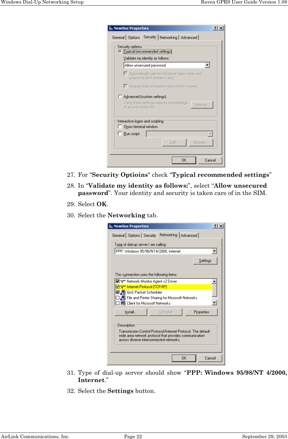
![Raven and PinPoint AT Command Reference Raven GPRS User Guide Version 1.08 AirLink Communications, Inc. Page 46 September 29, 2003 Command Description S211=n [?] Ignore DTR. For applications or situations where hardware control of the DTR signal is not possible, the modem can be configured to ignore DTR. When Ignore DTR is enabled, the modem operates as if the DTR signal is always asserted. n=0 [default]: Use hardware DTR. [&D2] n=1: Ignore DTR. [&D0] n=3: Ignore DTR and assert DSR. This value is deprecated, and it is recommended to use &S to control the DSR instead. When this value is set to 3, &S will automatically be set to 0. S221=n [?] Connect Delay [n = 0 - 255] n = number of seconds to delay the “CONNECT’ response upon establishing a TCP connection OR n = number of tenths of seconds to delay before outputting ENQ on the serial port after the CONNECT when the ENQ feature is enabled [see *ENQ] S300=n [?] Set or query whether a private or public (network) IP is to be used when the Host initiates a PPP connection to the modem. n = 0 [default]: Public (network) IP Mode: When the Host initiates a PPP connection, the host will be given the public IP that was obtained from the OEM Modem. If the network issues a new IP, the PPP connection will be closed (since the IP has changed) and has to be re-initiated. n = 1: Private IP Mode: When the Host initiates a PPP connection, the host will be given the IP address specified in S301. The modem will then perform NAT-like address translation, which shields the Host from network IP changes. S301=d.d.d.d [?] Set or query the private IP address that is to be negotiated by the PPP connection if S300=1. S302=d.d.d.d [?] Set or query the IP address that can be used to directly contact the modem once a PPP connection is established. If this value is not specified, 192.168.13.31 will be used. NOTE: This is not normally used nor needed by user applications. TCPS=n [?] TCP connection timeout (TCPT) units. n = 0: TCPT specifies minutes. n = 1: TCPT specifies seconds. TCPT=n [?] TCP connection timeout. Specifies a time interval upon which if there is no in or outbound traffic through a TCP connection, the connection will be terminated. This value only affects the TCP connection in TCP PAD mode. n = minutes (if TCPS=0) or seconds (if TCPS=1) Vn [?] Set or query Command Response Mode. n = 0: Terse (numeric) command responses n = 1: Verbose command responses (Default).](https://usermanual.wiki/Sierra-Wireless/R1902G.Exhibit-8-User-manual-3210/User-Guide-371352-Page-48.png)
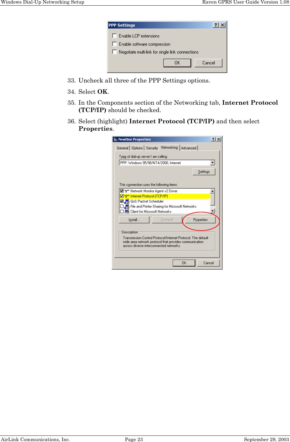
![Raven and PinPoint AT Command Reference Raven GPRS User Guide Version 1.08 AirLink Communications, Inc. Page 47 September 29, 2003 Command Description Xn [?] Extended Call Progress Result mode. n = 0: turn off extended result codes (Default) n = 1: turn on result codes. This adds the text 19200 to the CONNECT response. Z Reset the modem. NOTE: This command does nothing if *DATZ=1. &Cn [?] Set DCD mode. n = 0: Always assert DCD n = 1: Assert DCD when in a data mode (UDP, TCP, PPP, or SLIP) (Default). n = 2: Assert DCD when the modem has network coverage. &Dn [?] Set DTR mode. n = 0: Ignore DTR, same effect as HW DTR always asserted (same as S211=1) n = 2: Use hardware DTR (same as S211=0) &L<speed>,<databits> <parity><stop bits> Set serial line parameters (see S23) &Sn [?] Set DSR mode. n = 0: Always assert DSR n = 1: Assert DSR when in a data mode (UDP, TCP, PPP, or SLIP) (Default). n = 2: Assert DSR when the modem has network coverage. Note: Although deprecated, S211 can also be used to request that DSR is always asserted. If S211 is set to 3 and &S is changed to a non-zero value, S211 will be changed to 1. &V View active profile (the contents of the registers) &W Writes all changed modem settings. If this command is not issued, any modified values will revert back to their previous values at modem reset. &Z This command does nothing but does not cause an error either. \ACEPW=new123 Change the Ace password to a new value. Password is case sensitive. Default value is 12345 Example: AT\ACEPW=new123](https://usermanual.wiki/Sierra-Wireless/R1902G.Exhibit-8-User-manual-3210/User-Guide-371352-Page-49.png)
![Raven and PinPoint AT Command Reference Raven GPRS User Guide Version 1.08 AirLink Communications, Inc. Page 48 September 29, 2003 Command Description \APASSTHRU Set modem operation to pass through mode. This will pass any characters received on the serial port directly to the internal OEM Modem and output any characters from the internal OEM Modem out the serial port. This allows direct access/configuration of the OEM Modem. Once this mode is entered, the unit must be physically reset to return to normal operation. NOTE: It may take up to 30 seconds for the OEM Modem to respond after CONNECT is output. NOTE: This mode is not available through the remote AT telnet server. \APPP Set modem operation to PPP mode. The modem expects the Host to start PPP negotiation. DTR must be asserted or (&D0 or S211=1) \ASLIP Set modem operation to SLIP mode. DTR must be asserted or (&D0 or S211=1) \Qn [?] Set or query the serial port flow control setting. n = 0: No flow control is being used n = 2: RTS/CTS hardware flow control is being used n = 4: Transparent software flow control. Uses escaped XON and XOFF for flow control. XON and XOFF characters in data stream are escaped with the @ character (0x40). @ in data is sent as @@. *CTSE=n [?] Clear To Send Enable This feature asserts CTS when there is no network connection. Note: Flow control (AT\Q) will override this indication, so if you want to use CTS to indicate no network coverage, flow control has to be off (AT\Q0). RS232 voltage levels: Positive = Network coverage, Negative = no coverage. n = 0: Disabled (Default). n = 1: Enable assertion of CTS for network coverage. *DATE=[mm/dd/yyyy],[hh:mm:ss] [?] Sets and queries the clock in the unit. Either the date and time can be specified, or simply one of the two can be specified in which case the unspecified value will remain unchanged. The date and time are always specified in UTC (Universally Coordinated Time) and, as such, the hours are specified in 24-hours format. Note that if the product has a GPS (i.e. PinPoints), the GPS will be used to set the time, in which case any date/time specified will be ignored. *DATZ=n [?] Enables or disables reset on ATZ n = 0: Normal Reset (Default). n = 1: Disable Reset on ATZ. *DEVICEID=n [?] Sets or queries the 64-bit Device ID that is used by the modem to identify itself to the server. The default is a value that depends on the underlying communications technology being used.](https://usermanual.wiki/Sierra-Wireless/R1902G.Exhibit-8-User-manual-3210/User-Guide-371352-Page-50.png)
![Raven and PinPoint AT Command Reference Raven GPRS User Guide Version 1.08 AirLink Communications, Inc. Page 49 September 29, 2003 Command Description *DEVICEIDX=n [?] Same as *DEVICEID except entry of the 64-bit Device ID is in hexadecimal. *DNSn=d.d.d.d Sets the DNS addresses to be returned during PPP negotiation. If the underlying communications network provides DNS addresses, they replace those specified by this command. *DNS1 and *DNS2 are valid. *DOMAIN=[name] [?] (was *DOMAINSUFFIX) Domain (or domain zone) which the modem is in. This value is used during name resolutions if a fully qualified name is not provided and also for DNS updates. This value can be up to 20 characters long. If *DOMAIN=eairlink.com, then when ATDT@remote1 is entered, the fully qualified name remote1.eairlink.com will be used to perform a DNS query to resolve the name to an IP address. Note: Only letters, numbers, hyphen ‘-‘, and periods can be used in a domain name. *DPORT=n [?] Sets or queries the modem’s Device Port. Valid values are 1-65535. [See S110] *DU=n [?] Dial UDP Always The dial command always uses UDP, even when using ATDT n = 0: dial using the means specified [default] n = 1: dial UDP always, even when using ATDT NOTE: When this parameter is set you cannot establish a TCP PAD connection. *ENQ=n [?] Outputs an ENQ [0x05] after the TCP CONNECT delayed by the Delay Connect Response time [S221]. n = 0: Disabled (Default). n = 1: Enables ENQ on CONNECT. *MODEMNAME=[name][?] (was *DOMAINNAME) Name of the modem (up to 20 characters long) to use when performing IP change notifications to IPManager. This name should not be a fully qualified domain name, but simply the first portion. The value in *DOMAIN provides the domain zone to add to this name. For example if *MODEMNAME=mymodem and *DOMAIN=eairlink.com, then the modem’s fully qualified domain name is mymodem.eairlink.com. NOTE: Only letters, numbers, hyphen ‘-‘, and periods can be used in domain name. *NETCHAN? Returns the current active channel number. *NETIP? Query the current public (network) IP address of the modem. This is the IP address that was obtained from the embedded OEM Modem, and is the address to which packets can be sent in order to contact the modem from the Internet. NOTE: This could be 0.0.0.0 if there is no current network IP](https://usermanual.wiki/Sierra-Wireless/R1902G.Exhibit-8-User-manual-3210/User-Guide-371352-Page-51.png)
![Raven and PinPoint AT Command Reference Raven GPRS User Guide Version 1.08 AirLink Communications, Inc. Page 50 September 29, 2003 Command Description *NETOK Checks wireless network connection Responds OK if connected Responds ERROR if not connected *NETPHONE? Query the device’s phone number, if applicable or obtainable. *NETPW=pw [?] The password that is used to login to the wireless network, when required. *NETRSSI? Returns the current RSSI [Receive Signal Strength Indicator] of the modem as a negative dBm value. *NETSTATE? Query the current network state. Will get one of the following strings: Connecting To Network The modem is in the process of trying to connect to the network; Network Authentication Fail Authentication to the network has failed. Either *NETUID and *NETPW need to be updated, or the PDP Context [GPRS network] needs to be specified, or for some reason the network refuses to allow the modem to connect; Network Negotiation Fail Network connection negotiation failed. This is usually temporary and often clears up during a subsequent attempt; Network Ready Modem is connected to the network and ready to send data; Network Dormant Modem is connected to the network, but the link is dormant [CDMA network]. It will be woken up when data is sent or received; No Service There is no network service (e.g., no CDPD, no GPRS, or no CDMA service detected); Hardware Reset The OEM modem is being reset. This is a temporary state. *NETUID=uid [?] The login that is used to login to the wireless network, when required. *TPORT=ppppp [?] Sets or queries the port used for the AT Telnet server. Valid values are 0-65535. If 0 is specified, the AT Telnet server will be disabled. The default value is 2332. *UALL=n [?] Accepts UDP packets from any IP address when a UDP session is active. If there is no UDP session active, an incoming UDP packet will be treated according to the UDP auto answer and AIP settings. n = 0: No effect (Default). n = 1: Accept UDP data from all IP addresses when in a UDP session.](https://usermanual.wiki/Sierra-Wireless/R1902G.Exhibit-8-User-manual-3210/User-Guide-371352-Page-52.png)
![Raven and PinPoint AT Command Reference Raven GPRS User Guide Version 1.08 AirLink Communications, Inc. Page 51 September 29, 2003 Command Description *UDPLAST=n [?] If enabled, sets S53 to the last accepted IP address through UDP auto answer. This can be used in conjunction with MD3 so that when there is no UDP session, new serial host data will cause a connection to be restored to the last IP accepted through UDP auto answer. n = 0: Does not change S53 setting. (Default). n = 1: Set S53 to the last accepted IP. NOTE: This does not change the S53 setting in NVRAM. If the modem is reset, the original S53 setting will be restored from NVRAM. *USD=n [?] Inserts a delay between received UDP packets by a specified interval before sending them out to the serial port. n = 0: No UDP packet delay (Default). n = 1-255: Delay in 100ms units, from 100 ms to 25.5 sec.](https://usermanual.wiki/Sierra-Wireless/R1902G.Exhibit-8-User-manual-3210/User-Guide-371352-Page-53.png)
![Raven GPRS Technical Specifications Raven GPRS User Guide Version 1.08 AirLink Communications, Inc. Page 58 September 29, 2003 9.5 Status LED Display Channel [Chan] LED Flashing = Searching for a channel On = Found a channel Link LED Off = No GPRS service On = GPRS service is available on this channel Winking off = Roaming Winking on = GSM only signal, no GPRS. Registration (REG) LED: Off = No PPP link on GPRS network On = PPP link is established on GPRS network and have an IP address. RSSI LED – Indicates signal strength. Signal strength is denoted as follows: • < -100: RSSI LED off • –99 to –90: Blink every 1200ms • –89 to –80: Blink every 600ms • –79 to –70: Blink every 300ms • >= -69: RSSI LED on solid Transmit Receive (Tx/Rx) LED: Off = Idle On = Transmitting/Receiving (on RF) ERR LED Currently unused Power (PWR): Off = Power off On = Power on 9.6 Application Interface Features RS232, 1200 bps to 115.2 kbps AT Commands, PPP, SLIP, UDP, TCP](https://usermanual.wiki/Sierra-Wireless/R1902G.Exhibit-8-User-manual-3210/User-Guide-371352-Page-60.png)