Sierra Wireless SL5011 multi-band wireless modem User Manual AirPrime SL3010T Hardware Integration Guide
Sierra Wireless Inc. multi-band wireless modem AirPrime SL3010T Hardware Integration Guide
Contents
- 1. User Manual Revised
- 2. AirPrime - SL3010T - Hardware Integration Guide - Rev1.1
AirPrime - SL3010T - Hardware Integration Guide - Rev1.1
![4114511 Rev 1.1 August 02, 2013 11 Hardware Integration Guide Introduction 1.9. Hardware Development Components Sierra Wireless manufactures two hardware development components to facilitate the hardware integration process: AirPrime SL Socket Board — Adapter board on which an SL module is embedded. This board may be used as a stand-alone platform for basic hardware development. AirPrime SL Development Kit — Hardware development board on which an SL socket board is plugged. The development kit provides access to all of the interfaces supported by the SL module. For instructions on using the SL Development Kit, see document [2] AirPrime SL Series Universal Development Kit User Guide and [3] AirPrime SL Series Mechanical Socket Development Kit Quick Start Guide.](https://usermanual.wiki/Sierra-Wireless/SL5011.AirPrime-SL3010T-Hardware-Integration-Guide-Rev1-1/User-Guide-2051458-Page-13.png)
![4114511 Rev 1.1 August 02, 2013 33 Hardware Integration Guide Regulatory Approval 4. A label must be affixed to the outside of the end product into which the SL3010T modem is incorporated, with a statement similar to the following: This device contains FCC ID: N7NSL5011 5. A user manual with the end product must clearly indicate the operating requirements and conditions that must be observed to ensure compliance with current FCC/IC RF exposure guidelines. The end product with an embedded SL3010T modem may also need to pass the FCC Part 15 unintentional emission testing requirements and be properly authorized. Note: If this module is intended for use in a portable device, you are responsible for separate approval to satisfy the SAR requirements of FCC Part 2.1093 and IC RSS-102. 6.2. Integration Requirements When integrating the SL3010T, the following items need to be addressed: Mounting, and its effect on temperature, shock, and vibration performance Power supply, and the impact on battery drain and possible RF interference Antenna location and type, and their impact on RF performance Regulatory approvals, as described in this section Service provisioning, manufacturing process Software, as described in document [1] AirPrime SL3010T Product Technical Specification and Customer Design Guidelines Host interface, compliance with interface voltage levels Note: Sierra Wireless provides guidelines for successful integration of the SL3010T in the document suite; and also offers integration support services as necessary.](https://usermanual.wiki/Sierra-Wireless/SL5011.AirPrime-SL3010T-Hardware-Integration-Guide-Rev1-1/User-Guide-2051458-Page-35.png)
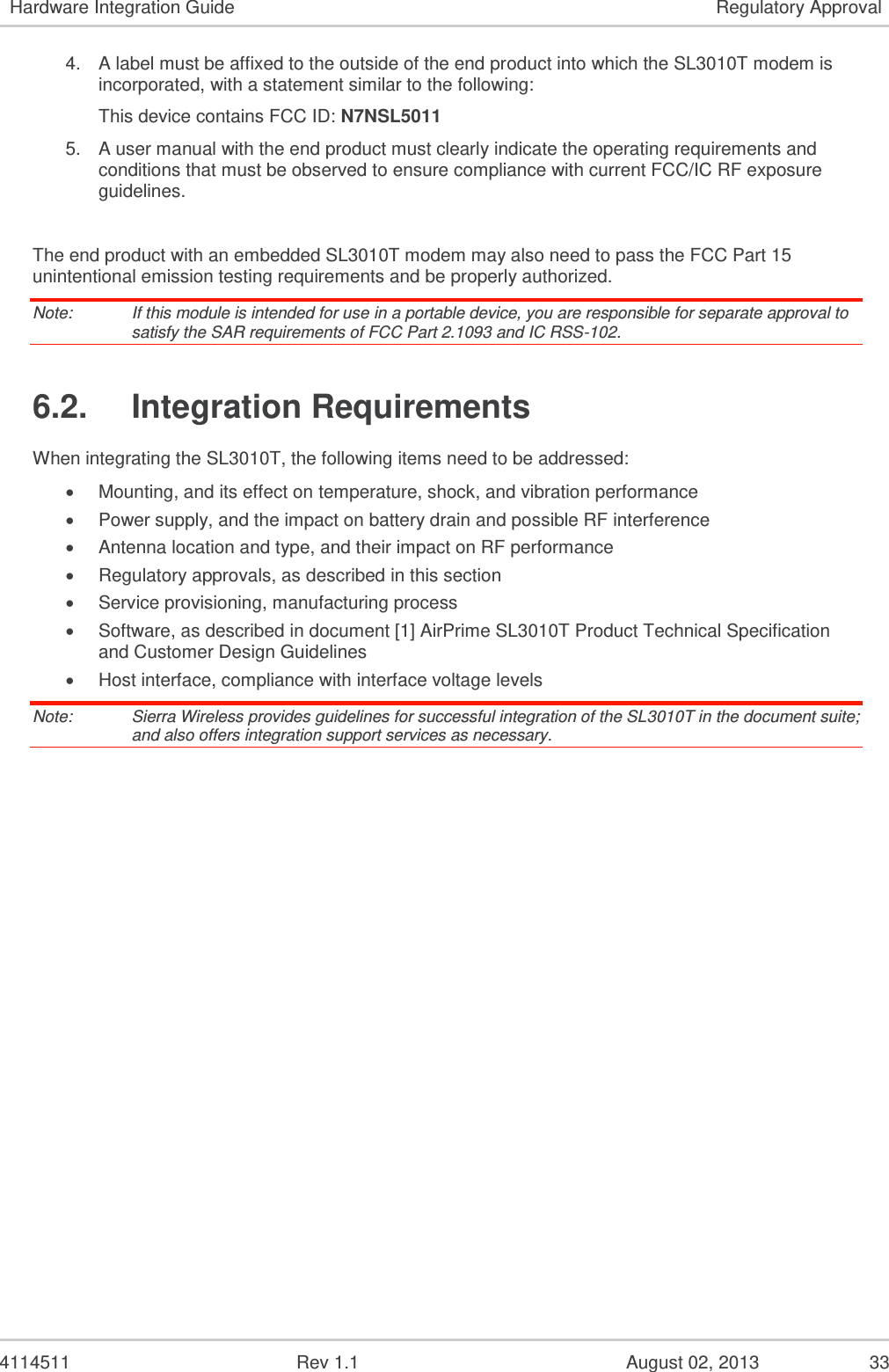
![4114511 Rev 1.1 August 02, 2013 34 7. References 7.1. Sierra Wireless Documentation [1] AirPrime SL3010T Product Technical Specification and Customer Design Guidelines Reference: 4112902 [2] AirPrime SL Series Universal Development Kit User Guide Reference number: WA_DEV_LG_UGD_003 [3] AirPrime SL Series Mechanical Socket Development Kit Quick Start Guide Reference number: 4112314 [4] AT Command Reference Guide Reference: 2130620 [5] EMConnect Guide Reference: 2131177 [6] CnS Reference Reference: 2130754 7.2. Acronyms and Definitions Table 21. Acronyms and Definitions Acronym or Term Definition 1xEV-DO Single Carrier (1X) EVolution – Data Only. A high-speed standard for cellular packet data communications Supports Internet connections with data rates up to 3.1 Mbps (downlink from the network) and 1.8 Mbps (uplink to the network). Average data rates are roughly: for Rev. A: 600-1300 kbps (downlink from the network) and 300-400 kbps (uplink to the network); for Rev. 0: 400-700 kbps (downlink from the network) and 40-80 kbps (uplink to the network). Actual speed depends on the network conditions. Compare to 1X. 1X Single Carrier (1X) Radio Transmission Technology. A high-speed standard for cellular packet data communications Supports Internet connections with data rates up to 153 kbps (simultaneously in each direction—downlink and uplink). Actual speed depends on the network conditions. Compare to 1xEV-DO. API Application Programming Interface AT A set of modem commands, preceded by “AT,” originally developed by Hayes, Inc. for their modems. The structure (but not the specific commands, which vary greatly from manufacturer to manufacturer) is a de facto modem industry standard. CDG CDMA Development Group CDMA Code Division Multiple Access A wideband spread spectrum technique used in digital cellular, personal communications services, and other wireless networks. Wide channels (1.25 MHz) are obtained through spread spectrum transmissions, thus allowing many active users to share the same channel. Each user is assigned a unique digital code, which differentiates the individual conversations on the same channel. CDMAOne The IS-95 CDMA standard developed by QUALCOMM Inc.](https://usermanual.wiki/Sierra-Wireless/SL5011.AirPrime-SL3010T-Hardware-Integration-Guide-Rev1-1/User-Guide-2051458-Page-36.png)