Sierra Wireless SL5011 multi-band wireless modem User Manual Revised
Sierra Wireless Inc. multi-band wireless modem Revised
UserManual.wiki
>
Sierra Wireless
>
SL5011 User Manual
>
User Manual Revised
Contents
1.
User Manual Revised
2.
AirPrime - SL3010T - Hardware Integration Guide - Rev1.1
User Manual Revised
Navigation menu
Upload a User Manual
Namespaces
Wiki Guide
HTML
PDF
Info
Views
User Manual
Discussion / Help
Navigation
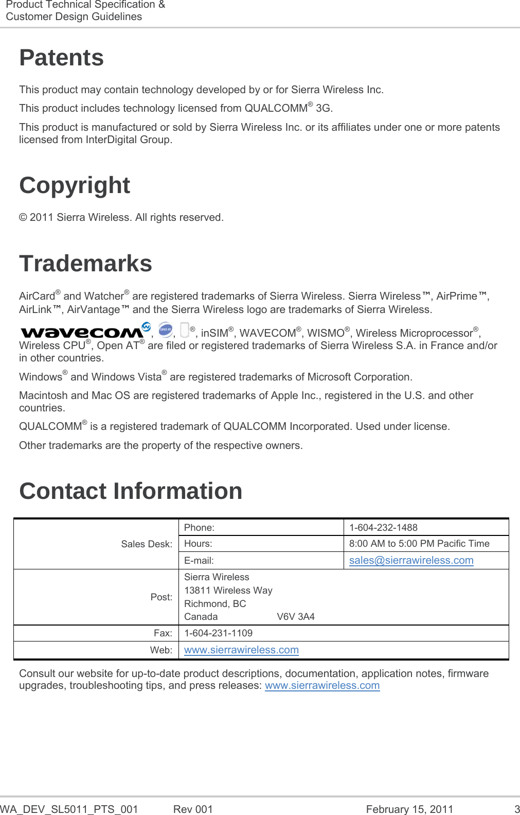
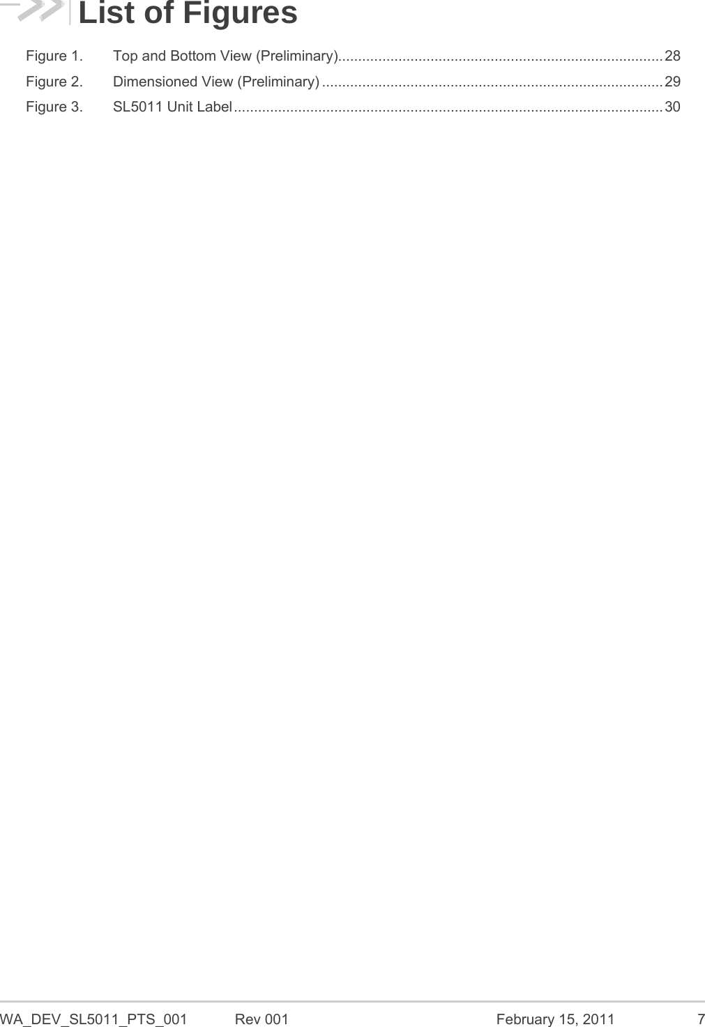
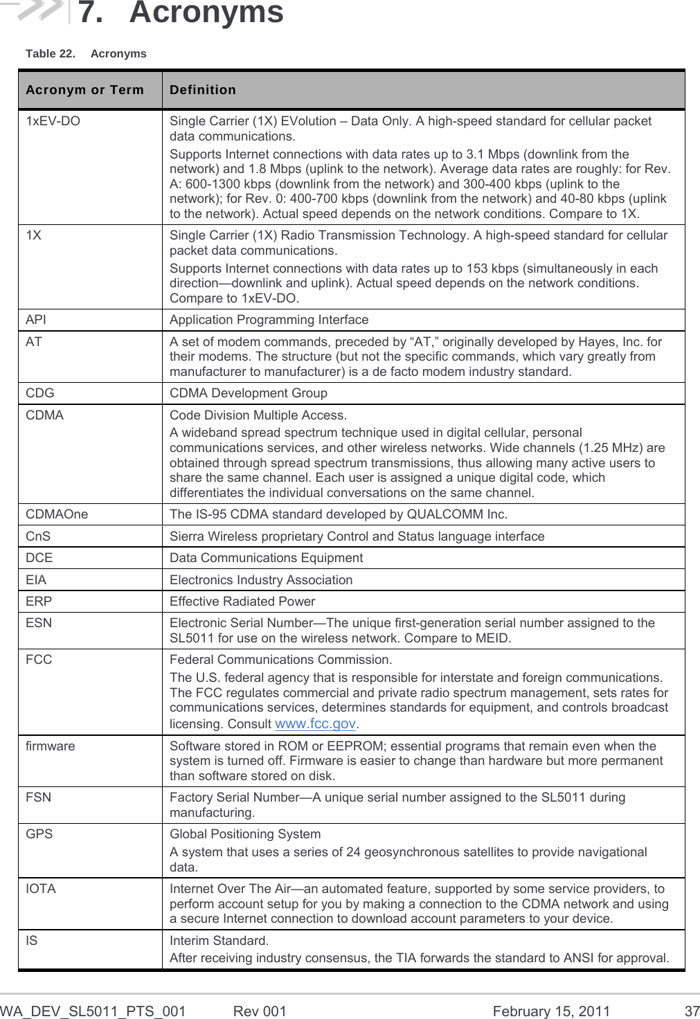
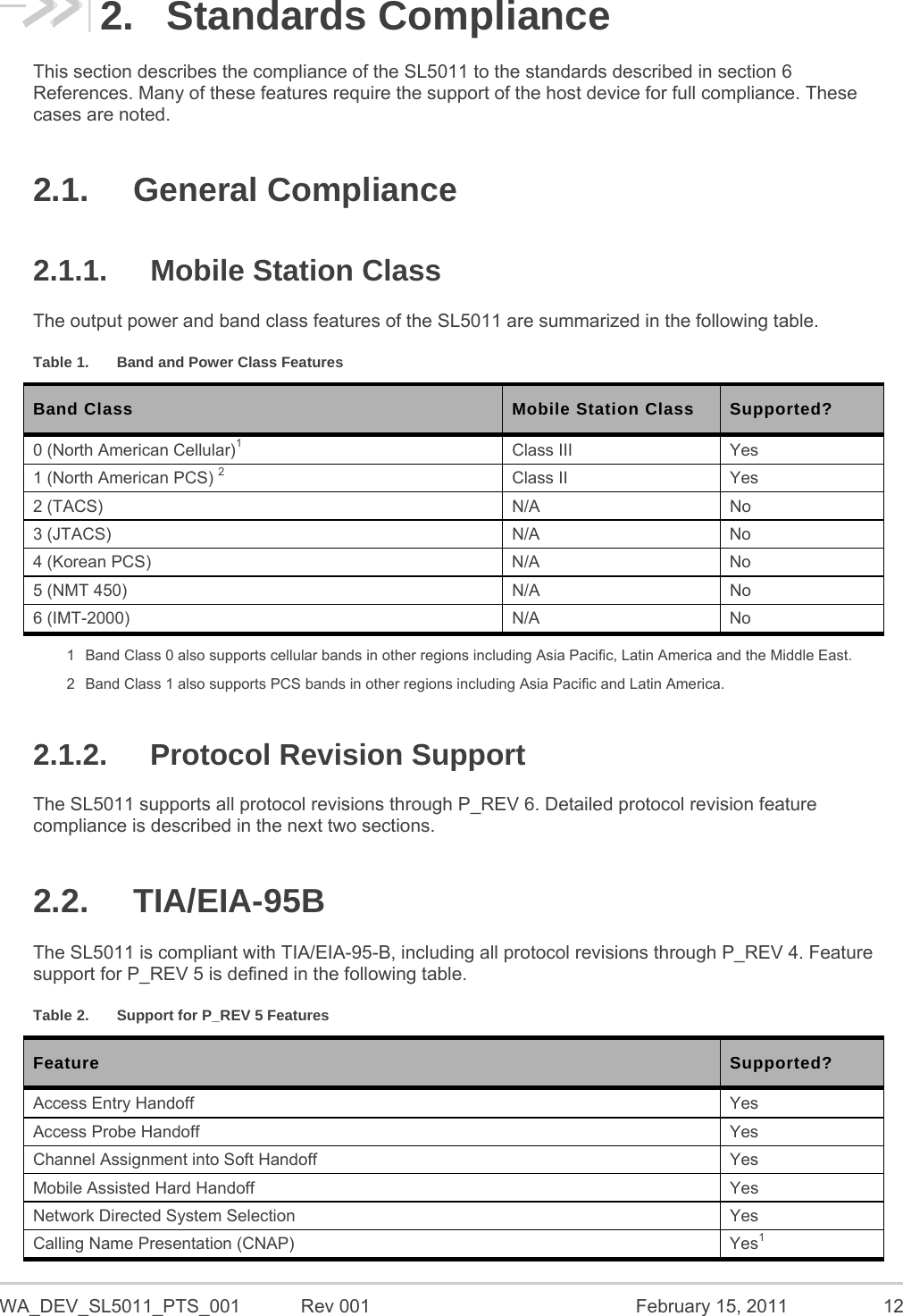
![WA_DEV_SL5011_PTS_001 Rev 001 February 15, 2011 10 Product Technical Specification & Customer Design Guidelines Introduction 1.4. RF Features Dual-band support for both the 800 MHz cellular and 1.9 GHz PCS bands Receive diversity support for the 800 MHz cellular and 1.9 GHz PCS bands Adheres to CDMA authentication as specified in CDMA 1X Support for IS-95A/B and CDMA 1X Release 0/A Support for IS-856 1xEV-DO Revision A Support for gpsOne™ and stand-alone GPS 1.5. Application Interface Features NDIS supported for Windows Vista, Windows XP, and Windows 2000 platforms USB supporting multiple logical channels over the USB MUX protocol USB selective suspend supported for maximum power savings Wakeup Enable – the module can be set to wake the host device upon ring, restoration of radio coverage, and/or receipt of SMS One UART port and one USB port AT command interface Limited RUIM feature for 1st release Sierra Wireless proprietary Control and Status (CnS) language interface Available Software Development Kit (SDK including an Application Program Interface (API) for Windows-based applications 1.6. EMConnect Features The SL5011 supports EMConnectTM – a robust set of firmware features that enables original equipment manufacturers (OEMs) to reduce their development time, platform costs and dependence on host processors. The SL5011 supports these EMConnect features: Enhanced serial (UART) interface PAD (Packet Assembler Dis-assembler) Connection Watchdog to ensure connectivity Enhanced GPIO Modem configuration persistence For more information on EMConnect, refer to document [44] EMConnect Guide. 1.7. Packet Mode Features IS-2000 data rates up to 153* kbps, simultaneous forward and reverse channel. IS-856 (1xEV-DO Rev. A) data rates up to 3.1 Mbps forward channel and 1.8 Mbps reverse channel. Note: * Data rate supported depends on network implementation.](https://usermanual.wiki/Sierra-Wireless/SL5011.User-Manual-Revised/User-Guide-1466841-Page-10.png)
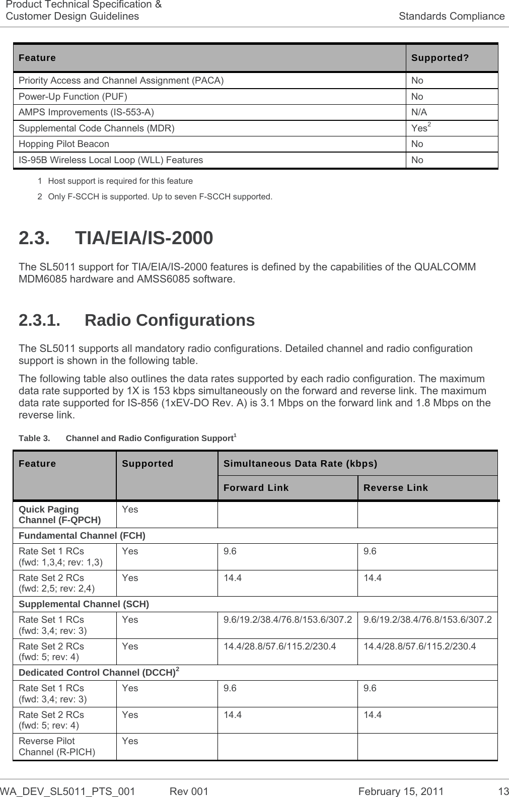

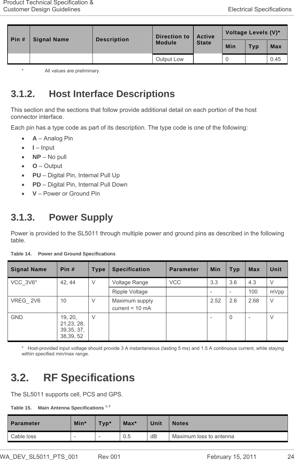
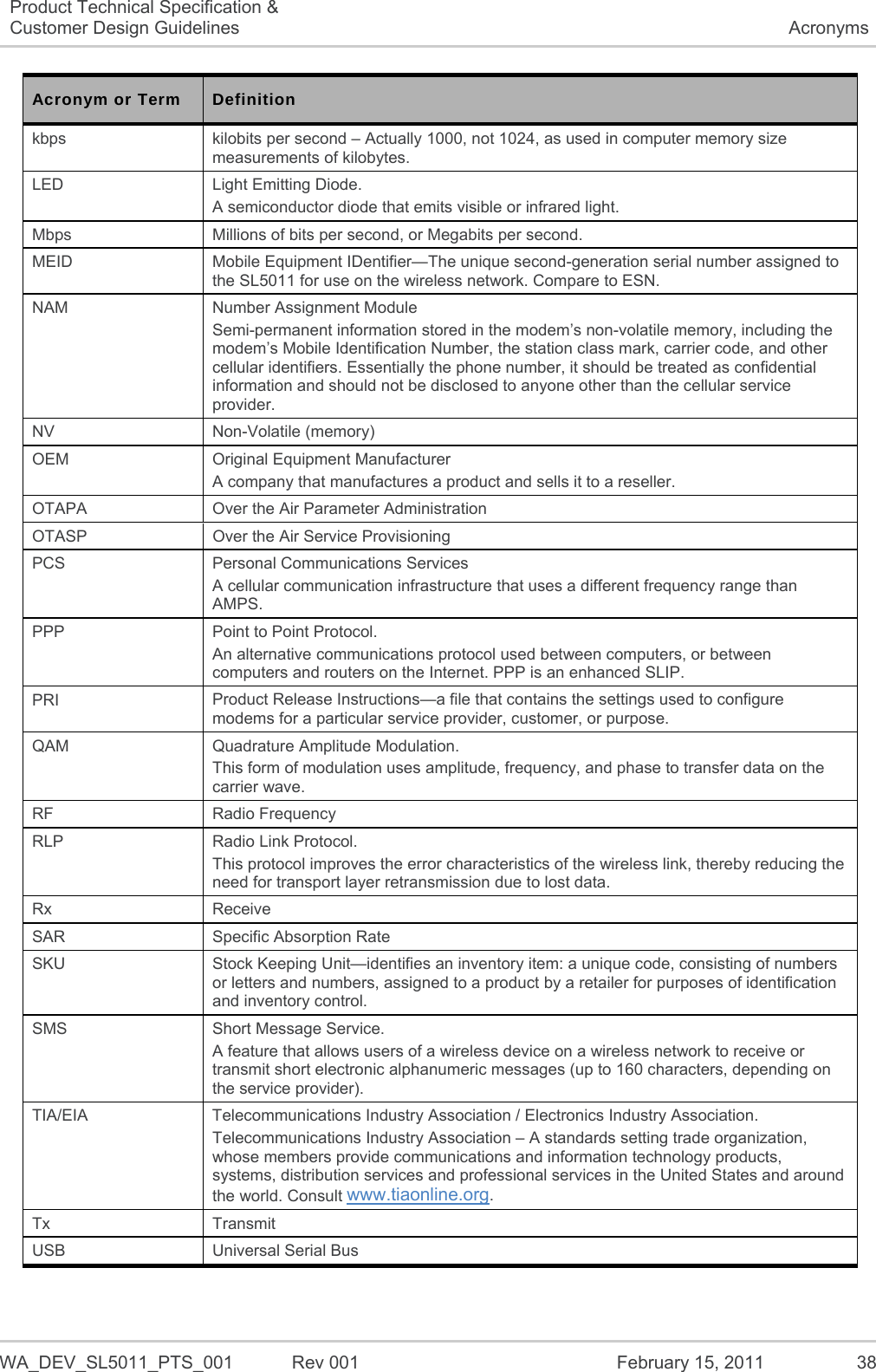
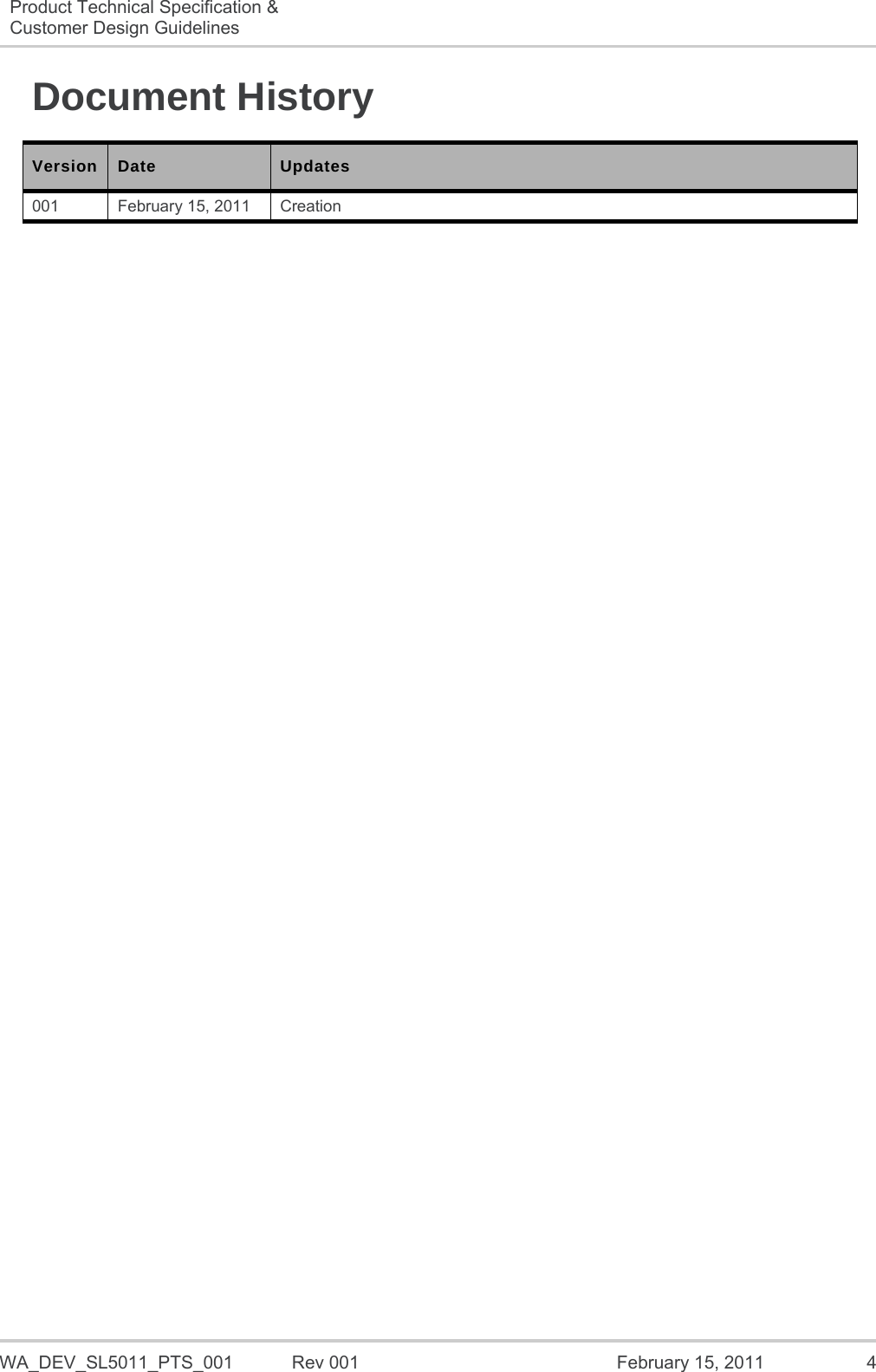
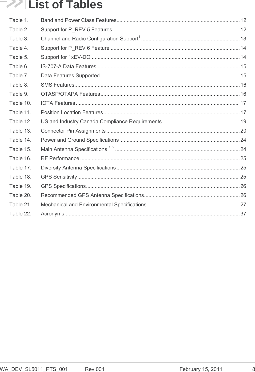
![WA_DEV_SL5011_PTS_001 Rev 001 February 15, 2011 25 Product Technical Specification & Customer Design Guidelines Electrical Specifications Parameter Min* Typ* Max* Unit Notes Impedance - 50 - Antenna load impedance VSWR - - 2.5:1 Maximum allowed VSWR of antenna 1 Sierra Wireless provides detailed antenna requirements in device integration guides (for example, document [45] Hardware Integration Guide). Contact Sierra Wireless for further information. 2 Main antenna connects to pin 29 * Preliminary values Table 16. RF Performance Parameter Min Typ Max Unit Notes Maximum output power +23.0 +24.0 +25.0 dBm +25.0 dBm is the maximum output power for IS-95, IS-2000, 1xEV-DO Revision 0, and 1xEV-DO Revision A. RX sensitivity (US Cell) - -107 - dBm IS-2000 SO2 RX sensitivity (US PCS) - -107 - dBm IS-2000 SO2 RX sensitivity (US Cell) - -110 - dBm 1xEV-DO Revision 0, DRC4 RX sensitivity (US PCS) - -109 - dBm 1xEV-DO Revision 0, DRC4 Table 17. Diversity Antenna Specifications Parameter Min Typ Max Unit Notes Cable loss - - 0.5 dB Maximum loss to antenna Impedance - 50 - Antenna load impedance VSWR - - 2.5:1 Maximum allowed VSWR of antenna Isolation between main and diversity antenna 10 - - dB Minimum isolation If the antenna connection is shorted or open, the radio module will not sustain permanent damage. For additional information, see document [45] Hardware Integration Guide. Table 18. GPS Sensitivity Parameter Typical Unit Notes Single-satellite sensitivity w/SA -155 dBm Sensitivity is where 50% of the visible satellites can be acquired](https://usermanual.wiki/Sierra-Wireless/SL5011.User-Manual-Revised/User-Guide-1466841-Page-25.png)
![WA_DEV_SL5011_PTS_001 Rev 001 February 15, 2011 34 6. References 6.1. Standards 6.1.1. TIA/EIA Standards TIA standards are available at www.tiaonline.org. [1] TIA/EIA/IS-2000.1 through .6. CDMA2000® Standards for Spread Spectrum Systems. Release 0. April 2000. [2] TIA/EIA/IS-2000.1-1 through .6-1. CDMA2000® Addendum 1. April 2000. [3] TIA/EIA/IS-2000.1-2 through .6-2. CDMA2000® Addendum 2. June 2001. [4] TIA/EIA-95-B. Mobile Station-Base Station Compatibility Standard for Dual-Mode Spread Spectrum Systems. December 4, 1998. [5] TIA/EIA/IS-707-A. Data Service Options for Wideband Spread Spectrum Systems. March 2000. [6] TIA/EIA/IS-134. Facsimile Digital Interfaces - Amendments to TIA/EIA-592 to Support ITU-T T.30-1993. October 1994. [7] TIA/EIA-592. Asynchronous Facsimile DCE Control Standard - Service Class 2. April 1998. [8] TIA/EIA-617. Data Transmission Systems and Equipment for In-Band DCE Control. January 1996. [9] TIA/EIA/IS-733-1. High Rate Speech Service Option 17 for Wideband Spread Spectrum Communication Systems. September 1999. [10] TIA/EIA/IS-736. Recommended Minimum Performance Standard for the High Rate Speech Service Option 17 for Spread Spectrum Communication Systems. August 2000. [11] TIA/EIA/IS-127-2. Enhanced Variable Rate Codec, Speech Service Option 3 for Wideband Spread Spectrum Digital Systems - Addendum 2. September 1999. [12] TIA/EIA/IS-718. Minimum Performance Specification for the Enhanced Variable Rate Codec, Speech Service Option 3 for Spread Spectrum Digital Systems. July 1998. [13] TIA/EIA-637-B. Short Message Service for Wideband Spread Spectrum Cellular Systems. January 2002. [14] TIA/EIA/IS-683-A. Over-the-Air Service Provisioning of Mobile Stations in Spread Spectrum Systems. June 1998. [15] TIA/EIA/IS-835-A. Wireless IP Network Standard. May 2001. [16] TIA/EIA/IS-870. Test Data Service Option (TDSO) for CDMA2000® Spread Spectrum Systems. 2001. [17] TIA/EIA/IS-98D/E. Recommended Minimum Performance Standards for Dual-Mode Spread Spectrum Mobile Stations. [18] TIA/EIA/IS-866. Recommended Minimum Performance Standards for CDMA2000® High Rate Packet Data Access Terminal. [19] TIA/EIA-126-D. Mobile Station Loop back Service Options Standard. 2001. [20] TIA/EIA TSB 58-C. Administration of Parameter Value Assignments for TIA/EIA Wideband Spread Spectrum Standards. May 2000. [21] TIA/EIA TSB 50. User Interface for Authentication Key Entry. March 1993.](https://usermanual.wiki/Sierra-Wireless/SL5011.User-Manual-Revised/User-Guide-1466841-Page-34.png)
![WA_DEV_SL5011_PTS_001 Rev 001 February 15, 2011 35 Product Technical Specification & Customer Design Guidelines References [22] TIA/EIA/IS-801.1. Location Service Standard for Dual-Mode Spread Spectrum Systems. March 2001. [23] C.S0031-0. Signaling Conformance Tests for CDMA2000® Spread Spectrum Systems, Ballot Resolution. Version 3GPP2 TSG- C v2.0 [24] C.S0036-0. Recommended Minimum Performance Specification for C.S0022-0 Spread Spectrum Mobile Stations. 3GPP2 C.S0036-0 v1.0. [25] TIA/EIA/IS-J-STD-036. Enhanced Wireless 9-1-1 Phase II. January 2001. [26] TIA/EIA/IS-856. CDMA2000® High Rate Packet Data Air Interface Specification. November 2000. 6.1.2. CDG Standards [27] CDG 22. Stage 2 Interoperability Tests (TIA/EIA/IS-95A). Ver. 8.0. September 2000. [28] CDG 53. Stage 2 Interoperability Tests (TIA/EIA/95B). Ver. 2.0. June 2000. [29] CDG 57. Stage 2 Interoperability Tests (TIA/EIA/IS-2000). Ver. 0.7. February 2001. [30] CDG 36. Markov Service Options for Wideband Spread Spectrum Systems Communications Systems. March 11, 1996. [31] CDG 64. CDG Stage 3 Testing for CDMA2000®. Ver. 1.0. August 2002. 6.1.3. Agency Standards [32] FCC 47 CFR - Part 15. Radio Frequency Devices. January 2001. [33] FCC 47 CFR - Part 22. Cellular Radiotelephone Services. October 1998. [34] FCC 47 CFR - Part 24. Personal Communications Services. October 1998. [35] Industry Canada ICES-003. Interference-Causing Equipment Standard - Digital Apparatus. November 22, 1997. [36] Industry Canada RSS-132. Cellular Telephones Employing New Technologies Operating in the Bands 824-849 MHz and 869-894 MHz. Issue 2. September 2005. [37] Industry Canada RSS-133. 2 GHz Personal Communications Services. September 25, 1999. [38] IEC 61000-4-2. Electrostatic Discharge Immunity Test. [39] JESD22-A114-B. +/- 1 kV Human Body Model. [40] JESD22-C101. +/- 125 V Charged Device Model. [41] FCC 47 CFR - Part 2. Frequency allocations and radio treaty matters; general rules and regulations. 6.1.4. Other Standards [42] Openwave_IOTA_Protocol_v2.0_Specifications_doc_v2.04. February 2002. [43] Universal Serial Bus Specification. Revision 2.0. www.usb.org/developers/docs.](https://usermanual.wiki/Sierra-Wireless/SL5011.User-Manual-Revised/User-Guide-1466841-Page-35.png)
![WA_DEV_SL5011_PTS_001 Rev 001 February 15, 2011 36 Product Technical Specification & Customer Design Guidelines References 6.2. Sierra Wireless Documentation [44] EMConnect Guide Reference: 2131177 [45] Hardware Integration Guide Reference: 2130114 [46] AT Command Reference Guide Reference: 2130620 [47] CnS Reference Reference: 2130754](https://usermanual.wiki/Sierra-Wireless/SL5011.User-Manual-Revised/User-Guide-1466841-Page-36.png)