Sierra Wireless SL5011 multi-band wireless modem User Manual Revised
Sierra Wireless Inc. multi-band wireless modem Revised
Contents
- 1. User Manual Revised
- 2. AirPrime - SL3010T - Hardware Integration Guide - Rev1.1
User Manual Revised

WA_DEV_SL5011_PTS_001
001
February 15, 2011
AirPrime SL5011
Product Technical Specification
& Customer Design Guidelines

WA_DEV_SL5011_PTS_001 Rev 001 February 15, 2011 2
Product Technical Specification &
Customer Design Guidelines
Important Notice
Due to the nature of wireless communications, transmission and reception of data can never be
guaranteed. Data may be delayed, corrupted (i.e., have errors) or be totally lost. Although significant
delays or losses of data are rare when wireless devices such as the Sierra Wireless modem are used
in a normal manner with a well-constructed network, the Sierra Wireless modem should not be used
in situations where failure to transmit or receive data could result in damage of any kind to the user or
any other party, including but not limited to personal injury, death, or loss of property. Sierra Wireless
accepts no responsibility for damages of any kind resulting from delays or errors in data transmitted or
received using the Sierra Wireless modem, or for failure of the Sierra Wireless modem to transmit or
receive such data.
Safety and Hazards
Do not operate the Sierra Wireless modem in areas where blasting is in progress, where explosive
atmospheres may be present, near medical equipment, near life support equipment, or any equipment
which may be susceptible to any form of radio interference. In such areas, the Sierra Wireless modem
MUST BE POWERED OFF. The Sierra Wireless modem can transmit signals that could interfere with
this equipment. Do not operate the Sierra Wireless modem in any aircraft, whether the aircraft is on
the ground or in flight. In aircraft, the Sierra Wireless modem MUST BE POWERED OFF. When
operating, the Sierra Wireless modem can transmit signals that could interfere with various onboard
systems.
Note: Some airlines may permit the use of cellular phones while the aircraft is on the ground and the door
is open. Sierra Wireless modems may be used at this time.
The driver or operator of any vehicle should not operate the Sierra Wireless modem while in control of
a vehicle. Doing so will detract from the driver or operator’s control and operation of that vehicle. In
some states and provinces, operating such communications devices while in control of a vehicle is an
offence.
Limitations of Liability
This manual is provided “as is”. Sierra Wireless makes no warranties of any kind, either expressed or
implied, including any implied warranties of merchantability, fitness for a particular purpose, or
noninfringement. The recipient of the manual shall endorse all risks arising from its use.
The information in this manual is subject to change without notice and does not represent a
commitment on the part of Sierra Wireless. SIERRA WIRELESS AND ITS AFFILIATES
SPECIFICALLY DISCLAIM LIABILITY FOR ANY AND ALL DIRECT, INDIRECT, SPECIAL,
GENERAL, INCIDENTAL, CONSEQUENTIAL, PUNITIVE OR EXEMPLARY DAMAGES INCLUDING,
BUT NOT LIMITED TO, LOSS OF PROFITS OR REVENUE OR ANTICIPATED PROFITS OR
REVENUE ARISING OUT OF THE USE OR INABILITY TO USE ANY SIERRA WIRELESS
PRODUCT, EVEN IF SIERRA WIRELESS AND/OR ITS AFFILIATES HAS BEEN ADVISED OF THE
POSSIBILITY OF SUCH DAMAGES OR THEY ARE FORESEEABLE OR FOR CLAIMS BY ANY
THIRD PARTY.
Notwithstanding the foregoing, in no event shall Sierra Wireless and/or its affiliates aggregate liability
arising under or in connection with the Sierra Wireless product, regardless of the number of events,
occurrences, or claims giving rise to liability, be in excess of the price paid by the purchaser for the
Sierra Wireless product.

WA_DEV_SL5011_PTS_001 Rev 001 February 15, 2011 3
Product Technical Specification &
Customer Design Guidelines
Patents
This product may contain technology developed by or for Sierra Wireless Inc.
This product includes technology licensed from QUALCOMM® 3G.
This product is manufactured or sold by Sierra Wireless Inc. or its affiliates under one or more patents
licensed from InterDigital Group.
Copyright
© 2011 Sierra Wireless. All rights reserved.
Trademarks
AirCard® and Watcher® are registered trademarks of Sierra Wireless. Sierra Wireless™, AirPrime™,
AirLink™, AirVantage™ and the Sierra Wireless logo are trademarks of Sierra Wireless.
, ,
®, inSIM®, WAVECOM®, WISMO®, Wireless Microprocessor®,
Wireless CPU®, Open AT® are filed or registered trademarks of Sierra Wireless S.A. in France and/or
in other countries.
Windows® and Windows Vista® are registered trademarks of Microsoft Corporation.
Macintosh and Mac OS are registered trademarks of Apple Inc., registered in the U.S. and other
countries.
QUALCOMM® is a registered trademark of QUALCOMM Incorporated. Used under license.
Other trademarks are the property of the respective owners.
Contact Information
Sales Desk:
Phone: 1-604-232-1488
Hours: 8:00 AM to 5:00 PM Pacific Time
E-mail: sales@sierrawireless.com
Post:
Sierra Wireless
13811 Wireless Way
Richmond, BC
Canada V6V 3A4
Fax: 1-604-231-1109
Web: www.sierrawireless.com
Consult our website for up-to-date product descriptions, documentation, application notes, firmware
upgrades, troubleshooting tips, and press releases: www.sierrawireless.com

WA_DEV_SL5011_PTS_001 Rev 001 February 15, 2011 4
Product Technical Specification &
Customer Design Guidelines
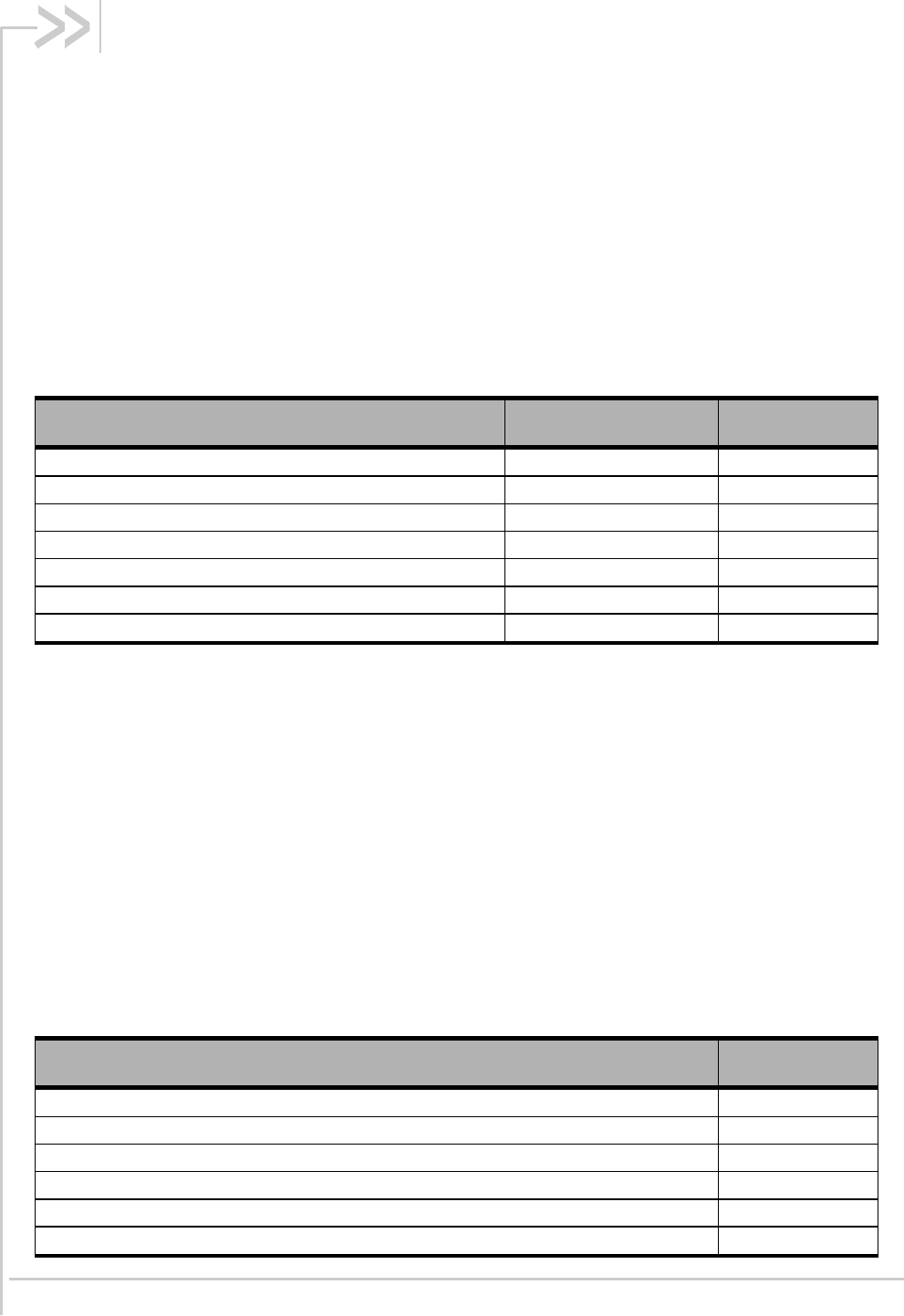
Document History
Version Date Updates
001 February 15, 2011 Creation

WA_DEV_SL5011_PTS_001 Rev 001 February 15, 2011 5
Contents
1.INTRODUCTION .................................................................................................. 9
1.1.Physical Features .............................................................................................................. 9
1.2.Electrical Features ............................................................................................................. 9
1.3.Environmental Features .................................................................................................... 9
1.4.RF Features ..................................................................................................................... 10
1.5.Application Interface Features ......................................................................................... 10
1.6.EMConnect Features ...................................................................................................... 10
1.7.Packet Mode Features .................................................................................................... 10
1.8.IS-95 Circuit-Switched Features ...................................................................................... 11
1.9.Short Message Service (SMS) Features ......................................................................... 11
2.STANDARDS COMPLIANCE ............................................................................ 12
2.1.General Compliance ........................................................................................................ 12
2.1.1.Mobile Station Class ................................................................................................ 12
2.1.2.Protocol Revision Support ........................................................................................ 12
2.2.TIA/EIA-95B ..................................................................................................................... 12
2.3.TIA/EIA/IS-2000............................................................................................................... 13
2.3.1.Radio Configurations ................................................................................................ 13
2.3.2.Release A Feature Support ...................................................................................... 14
2.4.TIA/EIA/IS-856 (1xEV-DO) .............................................................................................. 14
2.5.CDMA Data Services ...................................................................................................... 15
2.6.CDMA Short Message Service (SMS) ............................................................................ 16
2.7.Over-The-Air Service Provisioning (OTASP) .................................................................. 16
2.7.1.IS-683 Features ....................................................................................................... 16
2.7.2.Internet Over The Air (IOTA) Features .................................................................... 17
2.8.Position Location ............................................................................................................. 17
2.9.Additional Standards ....................................................................................................... 18
2.10.CDMA Certification Requirements .................................................................................. 18
2.10.1.CDMA Parametric Performance............................................................................... 18
2.10.2.Interoperability .......................................................................................................... 18
2.10.3.FCC and Industry Canada Type Acceptance .......................................................... 19
3.ELECTRICAL SPECIFICATIONS ...................................................................... 20
3.1.Host Interface .................................................................................................................. 20
3.1.1.Pin Assignments ...................................................................................................... 20
3.1.2.Host Interface Descriptions ...................................................................................... 24
3.1.3.Power Supply ........................................................................................................... 24
3.2.RF Specifications ............................................................................................................ 24
3.2.1.Recommended GPS Antenna Specifications .......................................................... 26
4.MECHANICAL AND ENVIRONMENTAL SPECIFICATIONS ............................ 27

WA_DEV_SL5011_PTS_001 Rev 001 February 15, 2011 6
Product Technical Specification &
Customer Design Guidelines
4.1.Labeling ........................................................................................................................... 30
5.REGULATORY APPROVAL .............................................................................. 31
6.REFERENCES ................................................................................................... 34
6.1.Standards ........................................................................................................................ 34
6.1.1.TIA/EIA Standards ................................................................................................... 34
6.1.2.CDG Standards ........................................................................................................ 35
6.1.3.Agency Standards .................................................................................................... 35
6.1.4.Other Standards ....................................................................................................... 35
6.2.Sierra Wireless Documentation ....................................................................................... 36
7.ACRONYMS ....................................................................................................... 37

WA_DEV_SL5011_PTS_001 Rev 001 February 15, 2011 7
List of Figures
Figure 1.Top and Bottom View (Preliminary)................................................................................. 28
Figure 2.Dimensioned View (Preliminary) ..................................................................................... 29
Figure 3.SL5011 Unit Label ........................................................................................................... 30

WA_DEV_SL5011_PTS_001 Rev 001 February 15, 2011 8
List of Tables
Table 1.Band and Power Class Features ..................................................................................... 12
Table 2.Support for P_REV 5 Features ........................................................................................ 12
Table 3.Channel and Radio Configuration Support1 .................................................................... 13
Table 4.Support for P_REV 6 Feature ......................................................................................... 14
Table 5.Support for 1xEV-DO ...................................................................................................... 14
Table 6.IS-707-A Data Features .................................................................................................. 15
Table 7.Data Features Supported ................................................................................................ 15
Table 8.SMS Features .................................................................................................................. 16
Table 9.OTASP/OTAPA Features ................................................................................................ 16
Table 10.IOTA Features ................................................................................................................. 17
Table 11.Position Location Features .............................................................................................. 17
Table 12.US and Industry Canada Compliance Requirements ..................................................... 19
Table 13.Connector Pin Assignments ............................................................................................ 20
Table 14.Power and Ground Specifications ................................................................................... 24
Table 15.Main Antenna Specifications 1, 2 ...................................................................................... 24
Table 16.RF Performance .............................................................................................................. 25
Table 17.Diversity Antenna Specifications ..................................................................................... 25
Table 18.GPS Sensitivity ................................................................................................................ 25
Table 19.GPS Specifications .......................................................................................................... 26
Table 20.Recommended GPS Antenna Specifications .................................................................. 26
Table 21.Mechanical and Environmental Specifications ................................................................ 27
Table 22.Acronyms ......................................................................................................................... 37

WA_DEV_SL5011_PTS_001 Rev 001 February 15, 2011 9
1. Introduction
The AirPrime SL5011 is a 74-pin soldered-down module based on the Intel pin-out specification
proposal for the standard JEDEC LGA packaging form factor. Its wireless modem provides CDMA
and 1xEV-DO wireless data connectivity for eBooks, portable navigation devices, mobile Internet
devices, point-of-sale devices, industrial handhelds and other machine-to-machine and vertical
applications. The SL5011 is part of a family of embedded wireless engines spanning a number of air
interface technologies and wide area networking protocols. It has a dual-band diversity radio
supporting the 800 MHz cellular and 1900 MHz PCS bands as well as GPS frequency band. The
modem is based on QUALCOMM’s MDM6085 integrated processor. The purpose of this document is
to describe the features and specifications of the module and to provide our OEM partners/customers
with the information required to integrate the SL5011 into their products. Application and hardware
interface requirements are discussed at a high level only; for more details, visit
www.sierrawireless.com.
1.1. Physical Features
Small form factor – Based on the 74-pin LGA Intel Moorestown form factor specification
(25mm x 30mm x 2.47mm (nominal))
1.2. Electrical Features
The SL5011 has one supply voltage:
VCC – Min 3.3 V, Max 4.3 V
The SL5011 is self-shielded; no additional shielding is required.
1.3. Environmental Features
Temperature operating range:
Normal use (3GPP compliant): -30°C to +70°C
Industry extended temperature range (non-3GPP compliant): <tbd>

WA_DEV_SL5011_PTS_001 Rev 001 February 15, 2011 10
Product Technical Specification &
Customer Design Guidelines Introduction
1.4. RF Features
Dual-band support for both the 800 MHz cellular and 1.9 GHz PCS bands
Receive diversity support for the 800 MHz cellular and 1.9 GHz PCS bands
Adheres to CDMA authentication as specified in CDMA 1X
Support for IS-95A/B and CDMA 1X Release 0/A
Support for IS-856 1xEV-DO Revision A
Support for gpsOne™ and stand-alone GPS
1.5. Application Interface Features
NDIS supported for Windows Vista, Windows XP, and Windows 2000 platforms
USB supporting multiple logical channels over the USB MUX protocol
USB selective suspend supported for maximum power savings
Wakeup Enable – the module can be set to wake the host device upon ring, restoration of
radio coverage, and/or receipt of SMS
One UART port and one USB port
AT command interface
Limited RUIM feature for 1st release
Sierra Wireless proprietary Control and Status (CnS) language interface
Available Software Development Kit (SDK including an Application Program Interface (API)
for Windows-based applications
1.6. EMConnect Features
The SL5011 supports EMConnectTM – a robust set of firmware features that enables original
equipment manufacturers (OEMs) to reduce their development time, platform costs and dependence
on host processors.
The SL5011 supports these EMConnect features:
Enhanced serial (UART) interface
PAD (Packet Assembler Dis-assembler)
Connection Watchdog to ensure connectivity
Enhanced GPIO
Modem configuration persistence
For more information on EMConnect, refer to document [44] EMConnect Guide.
1.7. Packet Mode Features
IS-2000 data rates up to 153* kbps, simultaneous forward and reverse channel.
IS-856 (1xEV-DO Rev. A) data rates up to 3.1 Mbps forward channel and 1.8 Mbps reverse
channel.
Note: * Data rate supported depends on network implementation.

WA_DEV_SL5011_PTS_001 Rev 001 February 15, 2011 11
Product Technical Specification &
Customer Design Guidelines Introduction
1.8. IS-95 Circuit-Switched Features
V.34 data rates to 14.4 kbps
G3 facsimile receive and transmit
Quick Net Connect (QNC) support
1.9. Short Message Service (SMS) Features
Send and receive
Notification of new messages
WA_DEV_SL5011_PTS_001 Rev 001 February 15, 2011 12
2. Standards Compliance
This section describes the compliance of the SL5011 to the standards described in section 6
References. Many of these features require the support of the host device for full compliance. These
cases are noted.
2.1. General Compliance
2.1.1. Mobile Station Class
The output power and band class features of the SL5011 are summarized in the following table.
Table 1. Band and Power Class Features
Band Class Mobile Station Class Supported?
0 (North American Cellular)1 Class III Yes
1 (North American PCS) 2 Class II Yes
2 (TACS) N/A No
3 (JTACS) N/A No
4 (Korean PCS) N/A No
5 (NMT 450) N/A No
6 (IMT-2000) N/A No
1 Band Class 0 also supports cellular bands in other regions including Asia Pacific, Latin America and the Middle East.
2 Band Class 1 also supports PCS bands in other regions including Asia Pacific and Latin America.
2.1.2. Protocol Revision Support
The SL5011 supports all protocol revisions through P_REV 6. Detailed protocol revision feature
compliance is described in the next two sections.
2.2. TIA/EIA-95B
The SL5011 is compliant with TIA/EIA-95-B, including all protocol revisions through P_REV 4. Feature
support for P_REV 5 is defined in the following table.
Table 2. Support for P_REV 5 Features
Feature Supported?
Access Entry Handoff Yes
Access Probe Handoff Yes
Channel Assignment into Soft Handoff Yes
Mobile Assisted Hard Handoff Yes
Network Directed System Selection Yes
Calling Name Presentation (CNAP) Yes1
WA_DEV_SL5011_PTS_001 Rev 001 February 15, 2011 13
Product Technical Specification &
Customer Design Guidelines Standards Compliance
Feature Supported?
Priority Access and Channel Assignment (PACA) No
Power-Up Function (PUF) No
AMPS Improvements (IS-553-A) N/A
Supplemental Code Channels (MDR) Yes2
Hopping Pilot Beacon No
IS-95B Wireless Local Loop (WLL) Features No
1 Host support is required for this feature
2 Only F-SCCH is supported. Up to seven F-SCCH supported.
2.3. TIA/EIA/IS-2000
The SL5011 support for TIA/EIA/IS-2000 features is defined by the capabilities of the QUALCOMM
MDM6085 hardware and AMSS6085 software.
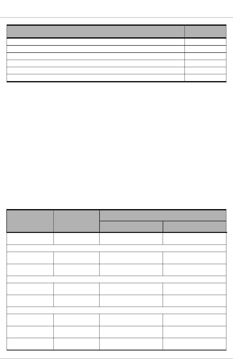
2.3.1. Radio Configurations
The SL5011 supports all mandatory radio configurations. Detailed channel and radio configuration
support is shown in the following table.
The following table also outlines the data rates supported by each radio configuration. The maximum
data rate supported by 1X is 153 kbps simultaneously on the forward and reverse link. The maximum
data rate supported for IS-856 (1xEV-DO Rev. A) is 3.1 Mbps on the forward link and 1.8 Mbps on the
reverse link.
Table 3. Channel and Radio Configuration Support1
Feature Supported Simultaneous Data Rate (kbps)
Forward Link Reverse Link
Quick Paging
Channel (F-QPCH) Yes
Fundamental Channel (FCH)
Rate Set 1 RCs
(fwd: 1,3,4; rev: 1,3)
Yes 9.6 9.6
Rate Set 2 RCs
(fwd: 2,5; rev: 2,4)
Yes 14.4 14.4
Supplemental Channel (SCH)
Rate Set 1 RCs
(fwd: 3,4; rev: 3)
Yes 9.6/19.2/38.4/76.8/153.6/307.2 9.6/19.2/38.4/76.8/153.6/307.2
Rate Set 2 RCs
(fwd: 5; rev: 4)
Yes 14.4/28.8/57.6/115.2/230.4 14.4/28.8/57.6/115.2/230.4
Dedicated Control Channel (DCCH)2
Rate Set 1 RCs
(fwd: 3,4; rev: 3)
Yes 9.6 9.6
Rate Set 2 RCs
(fwd: 5; rev: 4)
Yes 14.4 14.4
Reverse Pilot
Channel (R-PICH)
Yes

WA_DEV_SL5011_PTS_001 Rev 001 February 15, 2011 14
Product Technical Specification &
Customer Design Guidelines Standards Compliance
1 Support of maximum data rates is dependent on MSM supplier software, memory speed grade availability and network
implementation.
2 20 ms frames only
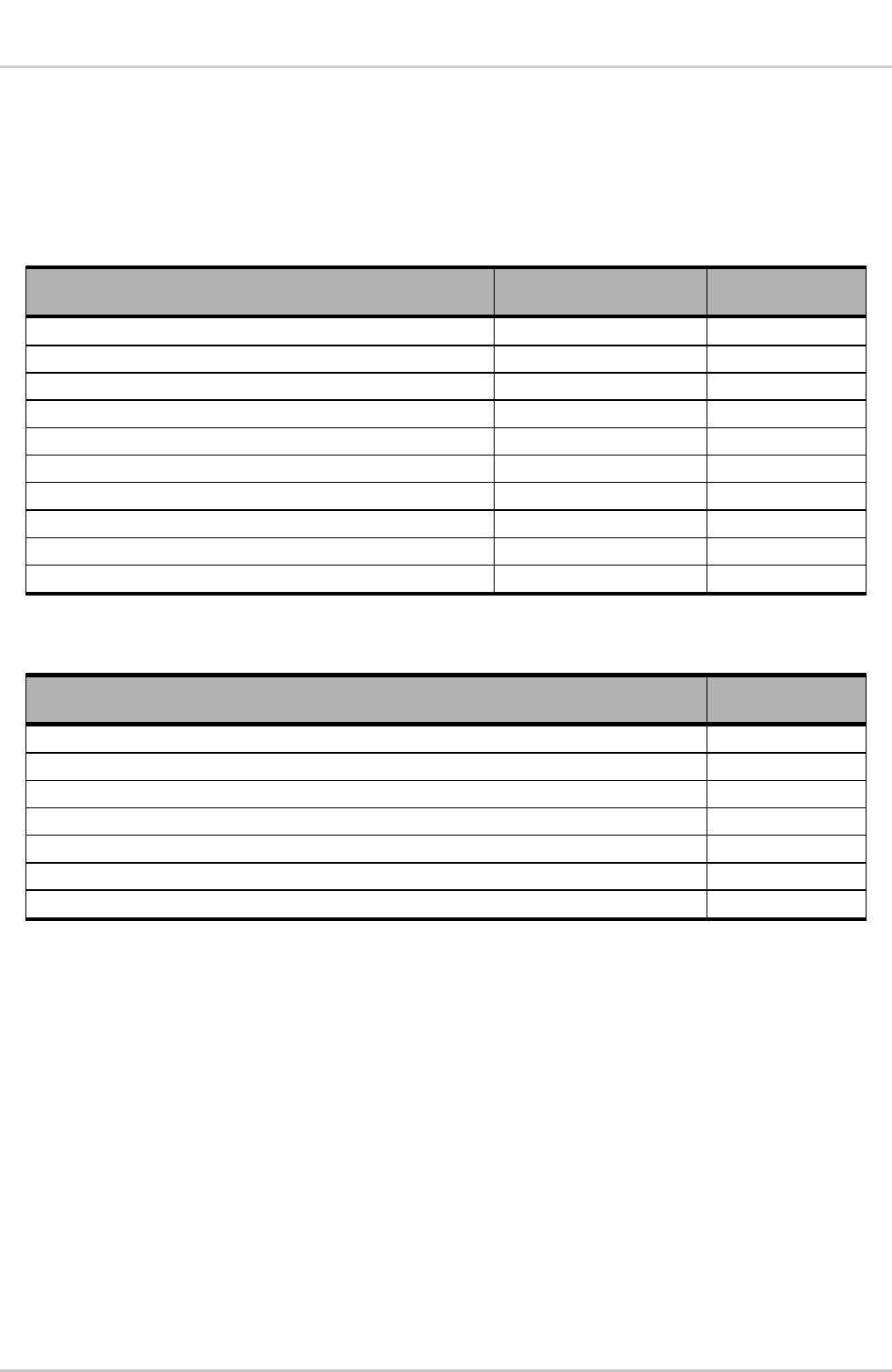
2.3.2. Release A Feature Support
The SL5011 supports all mandatory P_REV 6 features. Additional support for P_REV 6 features is
described in the following table. Note that not all Release A features may be supported by carriers or
network equipment.
Table 4. Support for P_REV 6 Feature
Optional P_REV 6 Feature Supported?
Simultaneous Maximum Data rates on Forward and Reverse Channels Yes
Quasi Orthogonal Functions (QOF) Yes
Turbo encoding/decoding Yes
Quick Paging Channel Yes
Slotted Mode Timer Yes
Orthogonal Transmit Diversity (OTD) Yes
Reverse Pilot Gating Yes
1/8 Rate Traffic Channel Gating Yes
Mobile Assisted Burst Operation (MABO) No
Traffic Channel Control Hold Yes
Short Data Bursts Yes
5 ms, 10 ms Frame sizes No
2.4. TIA/EIA/IS-856 (1xEV-DO)
The SL5011 supports TIA/EIA/IS-856-A (1xEV-DO) features as defined by the capabilities of the
QUALCOMM MDM6085 hardware and AMSS6085 software.
Table 5. Support for 1xEV-DO
Feature Supported?
Air Interface as defined by IS-856 Yes
Packet Data Service in Relay Mode Yes
Support for Test Application Specification (IS-890) Yes
Dual RF Receive Diversity Yes
1X/1xEV Hybrid Terminal Operation Yes
Connected State Off-Frequency Neighbor Search Yes
Slotted Mode (Sleep) Operation Yes
High Speed Broadcast Services (HSBS) Yes
Handoff Between IS-2000 and IS-856 Systems Yes
Quality of Service (QoS) Enhancements Yes
Data rates up to 3.1 Mbps on the forward channel and 1.8 Mbps on the reverse channel. Yes
WA_DEV_SL5011_PTS_001 Rev 001 February 15, 2011 15
Product Technical Specification &
Customer Design Guidelines Standards Compliance
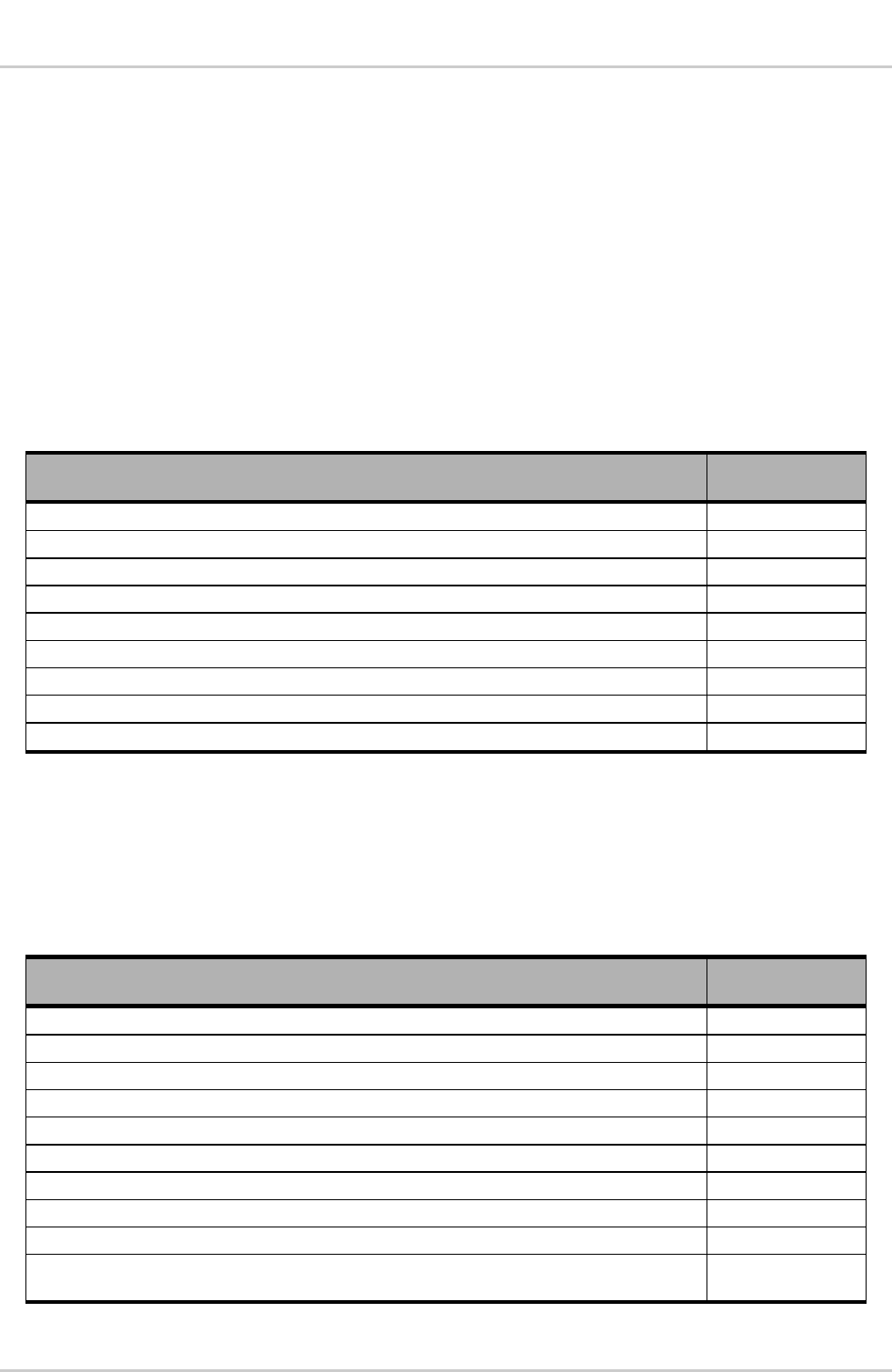
2.5. CDMA Data Services
The SL5011 supports the data features of IS-707-A as shown in the following table. Actual data
speeds supported by the SL5011 are shown in Table 3. The following table outlines support for
additional data features that are not part of IS-707-A.
Table 6. IS-707-A Data Features
CDMA Data Service IS-707-A Section Supported?
RLP IS-707.2 Yes*
AT Command Set IS-707.3 Yes
Asynchronous Data and Fax at 9.6 kbps and 14.4 kbps IS-707.4 Yes
Packet Data Service IS-707.5 Yes
STU-III IS-707.6 No
Analog Fax IS-707.7 No
Radio Link Protocol Type 2 (RLP2) IS-707.8 Yes
High Speed Packet Data (MDR - Medium Data Rate) IS-707.9 Yes
Radio Link Protocol Type 3 (RLP3) IS-707.10 Yes
CDMA High Speed Packet Data IS-707.12 Yes
* Encrypted mode and non-transparent modes are NOT supported.
Table 7. Data Features Supported
Features Supported?
Quick Net Connect Yes
Pre-arrangement for incoming Async data or fax Yes
In-Band DCE Control (TIA/EIA-617) Yes
Facsimile Digital Interfaces (TIA/EIA/IS-134) Yes
Asynchronous facsimile DCE Control Standard (TIA/EIA-592) Yes
Simple IP Yes
Mobile IP (TIA/EIA/IS-835-A) Yes

WA_DEV_SL5011_PTS_001 Rev 001 February 15, 2011 16
Product Technical Specification &
Customer Design Guidelines Standards Compliance
2.6. CDMA Short Message Service (SMS)
The following table summarizes the SL5011 compliance with SMS features per TIA/EIA/637-B. Note
that not all of these features are available on all carrier networks, and host device support is required
for compliance with these features. The SL5011 also complies with specific carrier requirements for
SMS as defined by each CDMA carrier.
Table 8. SMS Features
Feature Supported?
Mobile Terminated SMS Yes
Mobile Originated SMS Yes
Point-to-Point Messaging Yes
Broadcast Messaging Yes
Acknowledge Messaging Yes
Analog Mode SMS No
Wireless Paging Teleservice Yes
Wireless Messaging Teleservice Yes
Voice Mail Notification Yes
Wireless Application Teleservice Yes
Service Category Programming Teleservice Yes
2.7. Over-The-Air Service Provisioning (OTASP)
2.7.1. IS-683 Features
The SL5011 supports TIA/EIA/IS-683-A for Over-the-Air Service-Provisioning (OTASP) and
Parameter Administration (OTAPA) as summarized in the following table. The SL5011 also complies
with carrier specific OTASP and OTAPA requirements.
Table 9. OTASP/OTAPA Features
Feature Supported?
OTASP (user initiated) Yes*
OTAPA (network initiated) Yes
NAM Parameter Download Yes
Preferred Roaming List (PRL) Download Yes
A-Key Exchange Yes
OTAPA NAM Lock Yes
Re-Authenticate Messaging Yes
Protocol Capability Messaging Yes
* Host support is required for this feature.
WA_DEV_SL5011_PTS_001 Rev 001 February 15, 2011 17
Product Technical Specification &
Customer Design Guidelines Standards Compliance
2.7.2. Internet Over The Air (IOTA) Features
The SL5011 firmware includes an embedded IOTA client that includes the following support:
Automatically initiates and attempts to complete an IOTA session in the SL5011 when the
network initiates an IOTA session.
Provides an interface to the host to request the SL5011 to initiate and attempt a client initiated
IOTA session.
Provides notifications to the host of status and results of the current IOTA session in the
SL5011.
Provides an interface to the host to cancel, at any time, an active IOTA session running in the
SL5011.
IOTA feature support is defined in the following table.
Table 10. IOTA Features
Feature Supported?
Bootstrap Provisioning Yes*
Network Initiated Provisioning using WAP Push Yes
Reassembly of Multiple IOTA Trigger Messages Yes
HTTP and SSL Support (Download Agent) Yes
MMC XML and MIME Parser / Assembler Yes
IS-683-A/B Tunneling Yes
WBXML Parser / Assembler Yes
Bearer Selection Table Provisioning Yes
User NAI Profiles and CDMA Objects Yes
* Host support is required for this feature.
2.8. Position Location
The SL5011 supports position location features as specified in the following table.
Table 11. Position Location Features
Feature Supported?
TIA/EIA/IS-801.1 Compliant Yes
FCC E911 Phase II Position Determination Compliance Yes
TIA/EIA/IS-J-STD-036 Enhanced Wireless 9-1-1 Phase II Yes
TIA/EIA/IS-801.1 Compliant Data Burst Messaging Transport Yes
TIA/EIA/IS-801.1 Messaging Compliant TCP/IP Transport Yes
Mobile initiated, PDE calculated position Yes
PDE initiated, PDE calculated position (Mobile terminated request) Yes
Mobile calculated position Yes
Advanced Forward Link Trilateration (AFLT) Yes
Compliant with Snap Track Sensor Interface Application and Position Determination Entity
(SIA/PDE)
Yes

WA_DEV_SL5011_PTS_001 Rev 001 February 15, 2011 18
Product Technical Specification &
Customer Design Guidelines Standards Compliance
2.9. Additional Standards
The following additional standards, required for CDMA operation, are also supported:
TIA/EIA-126-D, Mobile Station Loop back Service Options Standard – Specifies loop back
service options used during testing and certification.
TIA/EIA TSB 50, User Interface for Authentication Key Entry – Specifies the method for A-
Key Entry from the device user interface.
Note: Requires host support for compliance.
TIA/EIA TSB 58-C, Parameter Value Assignments for TIA/EIA Wideband Spread
Spectrum Standards – Assigns values to reserved parameters and specifies which are
standard and which may be used for proprietary (manufacturer specific) values.
CDG 36, Markov Service Options for Wideband Spread Spectrum Systems
Communications Systems – Specifies the function of specific service options used for one-
way, over-the-air testing of mobiles.
TIA/EIA/IS-870, Test Data Service Option (TDSO) for CDMA2000® Spread Spectrum
Systems – Defines a test data service option for testing of CDMA2000® mobile units.
2.10. CDMA Certification Requirements
The SL5011 is designed to be fully compliant with the requirements below. However, final product
certification requires a fully integrated host device (that incorporates the SL5011).
Tests that require features not supported by the SL5011 (as defined in this document) are not
supported.
2.10.1. CDMA Parametric Performance
The SL5011 meets or exceeds TIA/EIA/IS-98D/E specifications for performance for CDMA2000®. The
SL5011 also meets or exceeds IS866 for 1xEV-DO specifications for performance.
2.10.2. Interoperability
The SL5011 complies with the following interoperability standards:
CDG 22 – Stage 2 Interoperability Tests (TIA/EIA/IS-95A)
CDG 53 – Stage 2 Interoperability Tests (TIA/EIA-95-B)
C.S0031-0 – Signaling Conformance Tests for CDMA2000® Spread Spectrum Systems
(Stage 2 for TIA/EIA/IS-2000)
CDG 64 – Stage 3 Testing for CDMA2000®
C.S0032 – Recommended Minimum Performance Standards for CDMA2000® High Rate
Packet Data Access Terminal (TIA/EIA/IS-866)

WA_DEV_SL5011_PTS_001 Rev 001 February 15, 2011 19
Product Technical Specification &
Customer Design Guidelines Standards Compliance
2.10.3. FCC and Industry Canada Type Acceptance
The SL5011 complies with the agency certifications specified in the following table.
Table 12. US and Industry Canada Compliance Requirements
Compliance Area US Regulation Industry Canada Regulation
Licensed transmission FCC Part 22, 24 RSS-132, RSS-133
Final product certification depends on the OEM host device and particularly the OEM antenna
implementation. Regulatory agency compliance testing is required for final product certification.
WA_DEV_SL5011_PTS_001 Rev 001 February 15, 2011 20
3. Electrical Specifications
3.1. Host Interface
The SL5011 host I/O connector provides pins for power, serial communications and control. The
details of these interfaces are described in the sections that follow.
3.1.1. Pin Assignments
The SL5011’s host connector provides the power, LED and USB communications through a single
connector. Detailed pin assignments are shown in the table below.
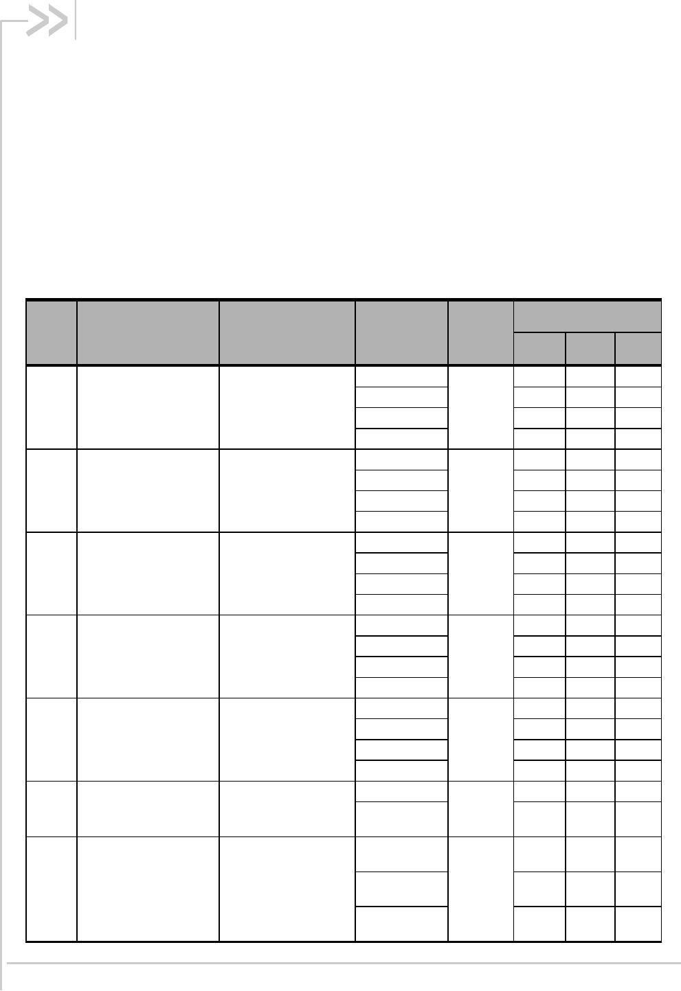
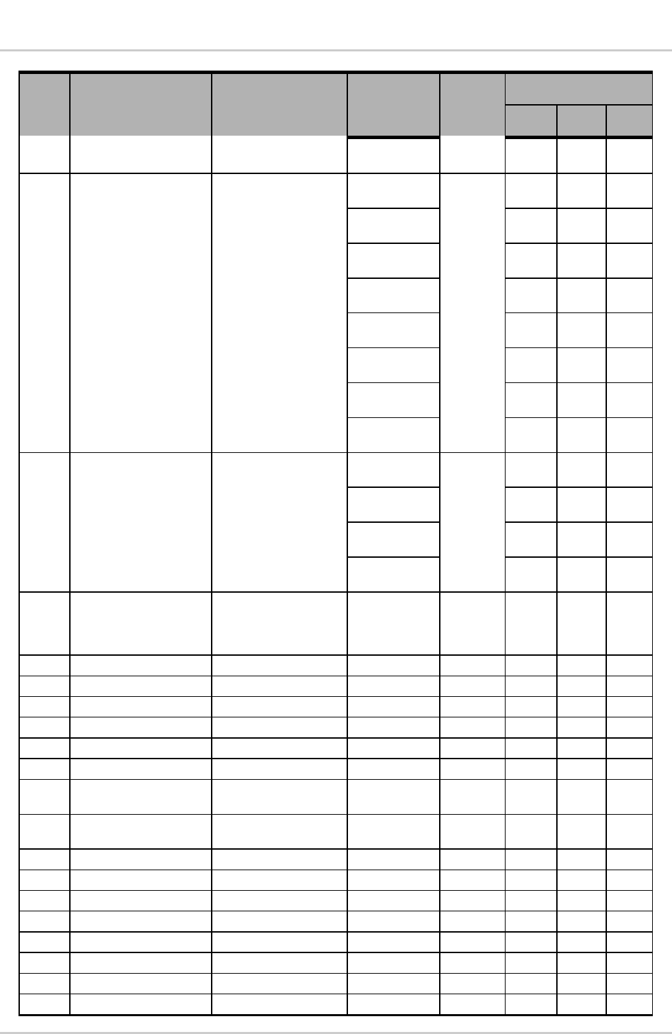
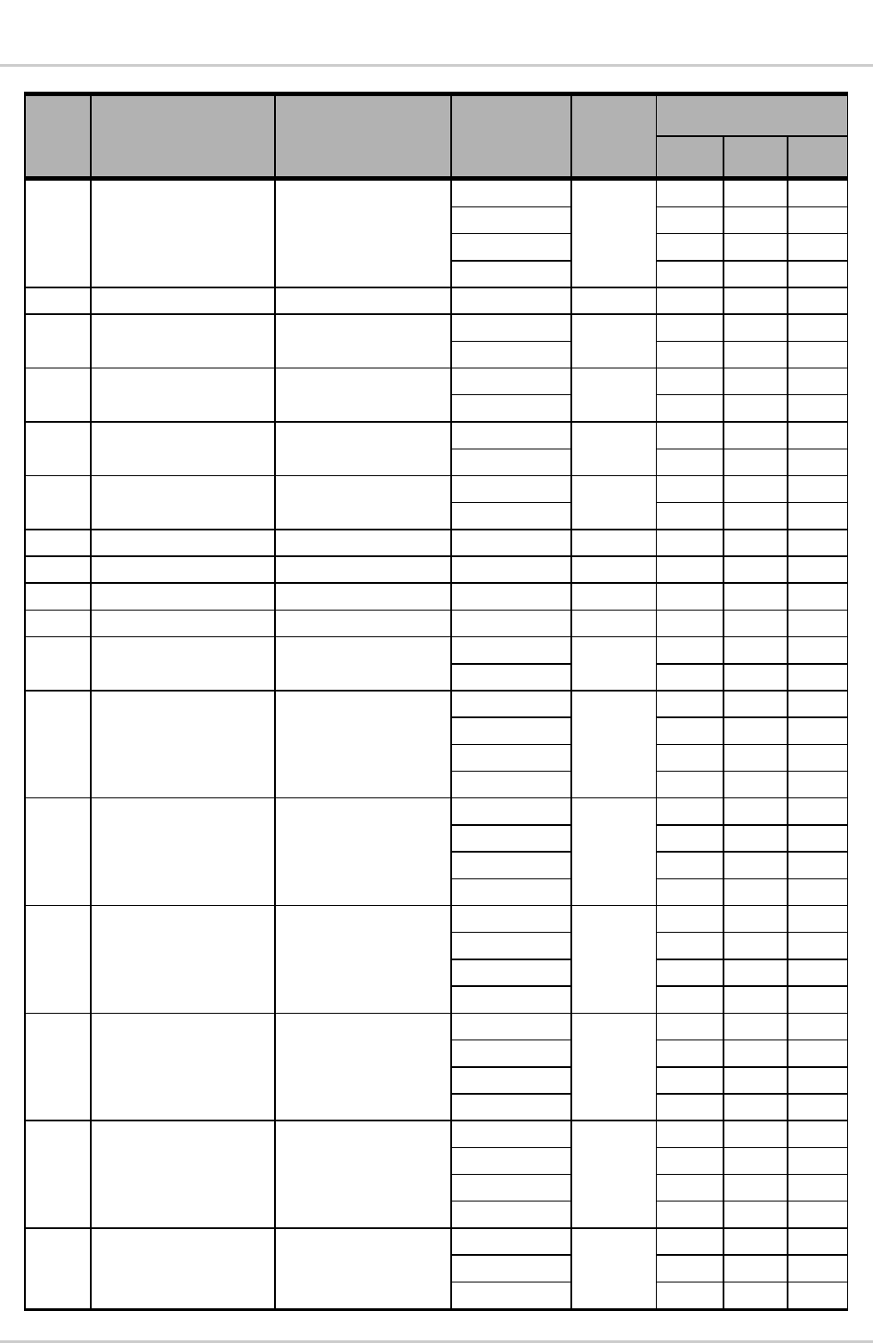
Table 13. Connector Pin Assignments
Pin # Signal Name Description Direction to
Module Active
State
Voltage Levels (V)*
Min Typ Max
1 GPIO_3 General purpose I/O
Input High
1.69 - 2.9
Input Low -0.3 0.91
Output High 2.15 2.6
Output Low 0 0.45
2 GPIO_2 General purpose I/O
Input High
1.69 - 2.9
Input Low -0.3 0.91
Output High 2.15 2.6
Output Low 0 0.45
3 GPIO_1 General purpose I/O
Input High
1.69 - 2.9
Input Low -0.3 0.91
Output High 2.15 2.6
Output Low 0 0.45
4 GPIO_4 General purpose I/O
Input High
1.69 - 2.9
Input Low -0.3 0.91
Output High 2.15 2.6
Output Low 0 0.45
5 GPIO_5 General purpose I/O
Input High
1.69 - 2.9
Input Low -0.3 0.91
Output High 2.15 2.6
Output Low 0 0.45
6 VREG_USIM USIM VCC supply
Output (1.8 V)
Power
1.60 1.80 1.90
Output
(3.0_V) 2.70 3.00 3.30
7 USIM_RESET_CONN USIM reset
Output High
(1.8V)
Low
1.44 1.80 2.10
Output Low
(1.8V) 0 0.40
Output High
(3.0V) 2.40 3.00 3.30
WA_DEV_SL5011_PTS_001 Rev 001 February 15, 2011 21
Product Technical Specification &
Customer Design Guidelines Electrical Specifications
Pin # Signal Name Description Direction to
Module Active
State
Voltage Levels (V)*
Min Typ Max
Output Low
(3.0V) 0 0.60
8 USIM_DATA_CONN USIM I/O pin
Input High
(1.8 V)
1.26 2.10
Input Low
(1.8 V) 0.00 0.40
Output High
(1.8 V) 1.26 1.80 2.10
Output Low
(1.8 V) 0 0.40
Input High
(3.0 V) 2.10 3.30
Input Low
(3.0 V) 0.00 0.60
Output High
(3.0 V) 2.10 3.00 3.30
Output Low
(3.0 V) 0.00 0.60
9 USIM_CLK_CONN USIM clock
Output High
(1.8V)
High
1.26 1.80 2.10
Output Low
(1.8V) 0.00 0.40
Output High
(3.0V) 2.10 3.00 3.30
Output Low
(3.0V) 0.00 0.60
10 VREG_ 2V6 2.6 V LDO Output
High
(when
module
is on)
2.52 2.6 2.68
11 NC Not connected
12 NC Not connected
13 NC Not connected
14 NC Not connected
15 NC Not connected
16 NC Not connected
17 ADC_1 Analog/Digital
conversion Input Input 0 - 2.1
18 ADC_2 Analog/Digital
conversion Input Input 0 - 2.1
19 GND Ground GND GND - - -
20 GND Ground GND GND - - -
21 GND Ground GND GND - - -
22 ANT_DIV Diversity antenna tbd tbd tbd
23 GND Ground GND GND - - -
24 NC Not connected
25 NC Not connected
26 NC Not connected

WA_DEV_SL5011_PTS_001 Rev 001 February 15, 2011 22
Product Technical Specification &
Customer Design Guidelines Electrical Specifications
Pin # Signal Name Description Direction to
Module Active
State
Voltage Levels (V)*
Min Typ Max
27 NC Not connected
28 GND Ground GND GND - - -
29 ANT_PRM Main (primary)
antenna tbd tbd tbd
30 GND Ground GND GND - - -
31 NC Not connected
32 NC Not connected
33 NC Not connected
34 NC Not connected
35 GND Ground GND GND - - -
36 ANT_GPS GPS antenna tbd tbd tbd
37 GND Ground GND GND - - -
38 GND Ground GND GND - - -
39 GND Ground GND GND - - -
40 NC Not connected
41 NC Not connected
42 VCC_3V6 3.6 V supply Input Power 3.3 3.6 4.3
43 POWER_ON_N Power on Input 0 2.6
44 VCC_3V6 3.6 V supply Input Power 3.3 3.6 4.3
45 UART1_RXD UART Receive Data Input High 1.69 - 2.9
Input Low -0.3 0.91
46 UART1_TXD UART Transmit Data Output High 2.15 2.6
Output Low 0 0.45
47 UART1_RTS_N UART Request To
Send
Output High 2.15 2.6
Output Low 0 0.45
48 UART1_CTS_N UART Clear To Send Input High 1.69 - 2.9
Input Low -0.3 0.91
49 NC Not connected
50 USB_D+ USB data positive
(Low/Full speed)
Input High
2.00 3.30 3.60
Input Low 0.00 0.80
Output High 2.80 3.30 3.60
Output Low 0.30
51 USB_D- USB data negative
(Low/Full speed)
Input High
2.00 3.30 3.60
Input Low 0.00 0.80
Output High 2.80 3.30 3.60
Output Low 0.30
52 GND Ground GND GND - - -
53 NC Not connected
54 NC Not connected
55 NC Not connected
56 NC Not connected
57 NC Not connected
WA_DEV_SL5011_PTS_001 Rev 001 February 15, 2011 23
Product Technical Specification &
Customer Design Guidelines Electrical Specifications
Pin # Signal Name Description Direction to
Module Active
State
Voltage Levels (V)*
Min Typ Max
58 NC Not connected
Input High
1.69 - 2.9
Input Low -0.3 0.91
Output High 2.15 2.6
Output Low 0 0.45
59 NC Not connected
60 LED_FLASH LED driver Output High 2.15 2.6
Output Low 0 0.45
61 WAKE_N Wake Host Interface Output High 2.15 2.6
Output Low 0 0.45
62 W_DISABLE_N Wireless disable Input High 1.69 - 2.9
Input Low -0.3 0.91
63 SYSTEM_RESET_N Reset Input High 1.17 - 2.1
Input Low -0.3 0.63
64 NC Not connected
65 NC Not connected
66 NC Not connected
67 NC Not connected
68 BUZZER_EN General purpose I/O
Output High 2.15 2.6
Output Low 0 0.45
69 TDI Test Data Input
Input High
1.69 - 2.9
Input Low -0.3 0.91
Output High 2.15 2.6
Output Low 0 0.45
70 TMS Test Mode Select
Input High
1.69 - 2.9
Input Low -0.3 0.91
Output High 2.15 2.6
Output Low 0 0.45
71 TCK Test Clock
Input High
1.69 - 2.9
Input Low -0.3 0.91
Output High 2.15 2.6
Output Low 0 0.45
72 TRST_N Test Reset
Input High
1.69 - 2.9
Input Low -0.3 0.91
Output High 2.15 2.6
Output Low 0 0.45
73 TDO Test Data Output
Input High
1.69 - 2.9
Input Low -0.3 0.91
Output High 2.15 2.6
Output Low 0 0.45
74 RTCK Return TCK
Input High
1.69 - 2.9
Input Low -0.3 0.91
Output High 2.15 2.6
WA_DEV_SL5011_PTS_001 Rev 001 February 15, 2011 24
Product Technical Specification &
Customer Design Guidelines Electrical Specifications
Pin # Signal Name Description Direction to
Module Active
State
Voltage Levels (V)*
Min Typ Max
Output Low 0 0.45
* All values are preliminary.
3.1.2. Host Interface Descriptions
This section and the sections that follow provide additional detail on each portion of the host
connector interface.
Each pin has a type code as part of its description. The type code is one of the following:
A – Analog Pin
I – Input
NP – No pull
O – Output
PU – Digital Pin, Internal Pull Up
PD – Digital Pin, Internal Pull Down
V – Power or Ground Pin
3.1.3. Power Supply
Power is provided to the SL5011 through multiple power and ground pins as described in the following
table.
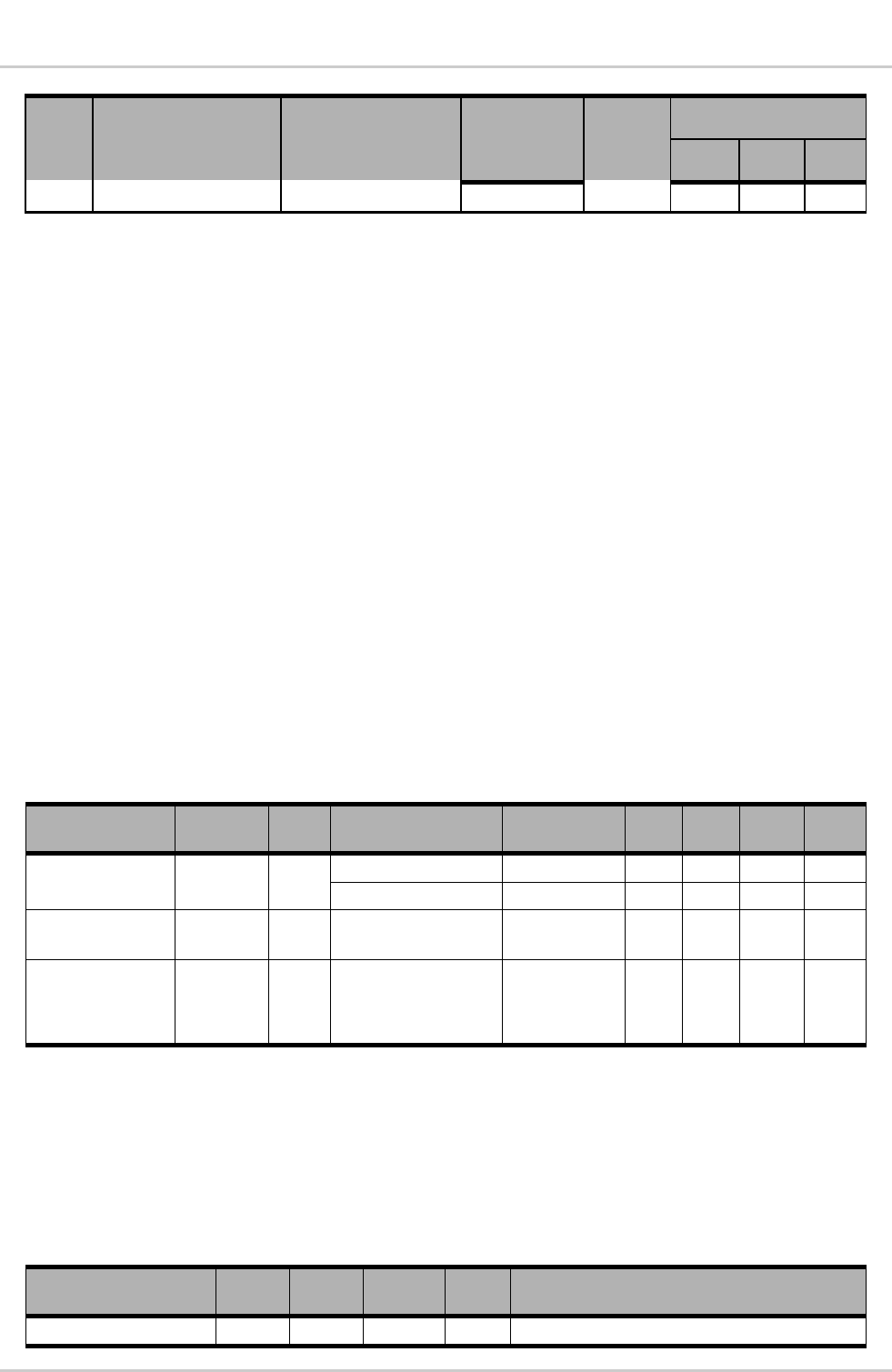
Table 14. Power and Ground Specifications
Signal Name Pin # Type Specification Parameter Min Typ Max Unit
VCC_3V6* 42, 44 V Voltage Range VCC 3.3 3.6 4.3 V
Ripple Voltage - - 100 mVpp
VREG_ 2V6 10 V Maximum supply
current = 10 mA
2.52 2.6 2.68 V
GND 19, 20,
21,23, 28,
39,35, 37,
38,39, 52
V - 0 - V
* Host-provided input voltage should provide 3 A instantaneous (lasting 5 ms) and 1.5 A continuous current, while staying
within specified min/max range.
3.2. RF Specifications
The SL5011 supports cell, PCS and GPS.
Table 15. Main Antenna Specifications 1, 2
Parameter Min* Typ* Max* Unit Notes
Cable loss - - 0.5 dB Maximum loss to antenna
WA_DEV_SL5011_PTS_001 Rev 001 February 15, 2011 25
Product Technical Specification &
Customer Design Guidelines Electrical Specifications
Parameter Min* Typ* Max* Unit Notes
Impedance - 50 - Antenna load impedance
VSWR - - 2.5:1 Maximum allowed VSWR of antenna
1 Sierra Wireless provides detailed antenna requirements in device integration guides (for example, document [45]
Hardware Integration Guide). Contact Sierra Wireless for further information.
2 Main antenna connects to pin 29
* Preliminary values
Table 16. RF Performance
Parameter Min Typ Max Unit Notes
Maximum output power +23.0 +24.0 +25.0 dBm +25.0 dBm is the maximum output power for
IS-95, IS-2000, 1xEV-DO Revision 0, and
1xEV-DO Revision A.
RX sensitivity (US Cell) - -107 - dBm IS-2000 SO2
RX sensitivity (US
PCS)
- -107 - dBm IS-2000 SO2
RX sensitivity (US Cell) - -110 - dBm 1xEV-DO Revision 0, DRC4
RX sensitivity (US
PCS)
- -109 - dBm 1xEV-DO Revision 0, DRC4
Table 17. Diversity Antenna Specifications
Parameter Min Typ Max Unit Notes
Cable loss - - 0.5 dB Maximum loss to antenna
Impedance - 50 - Antenna load impedance
VSWR - - 2.5:1 Maximum allowed VSWR of antenna
Isolation between main
and diversity antenna
10 - - dB Minimum isolation
If the antenna connection is shorted or open, the radio module will not sustain permanent damage.
For additional information, see document [45] Hardware Integration Guide.
Table 18. GPS Sensitivity
Parameter Typical Unit Notes
Single-satellite sensitivity w/SA -155 dBm Sensitivity is where 50% of the visible satellites
can be acquired
WA_DEV_SL5011_PTS_001 Rev 001 February 15, 2011 26
Product Technical Specification &
Customer Design Guidelines Electrical Specifications
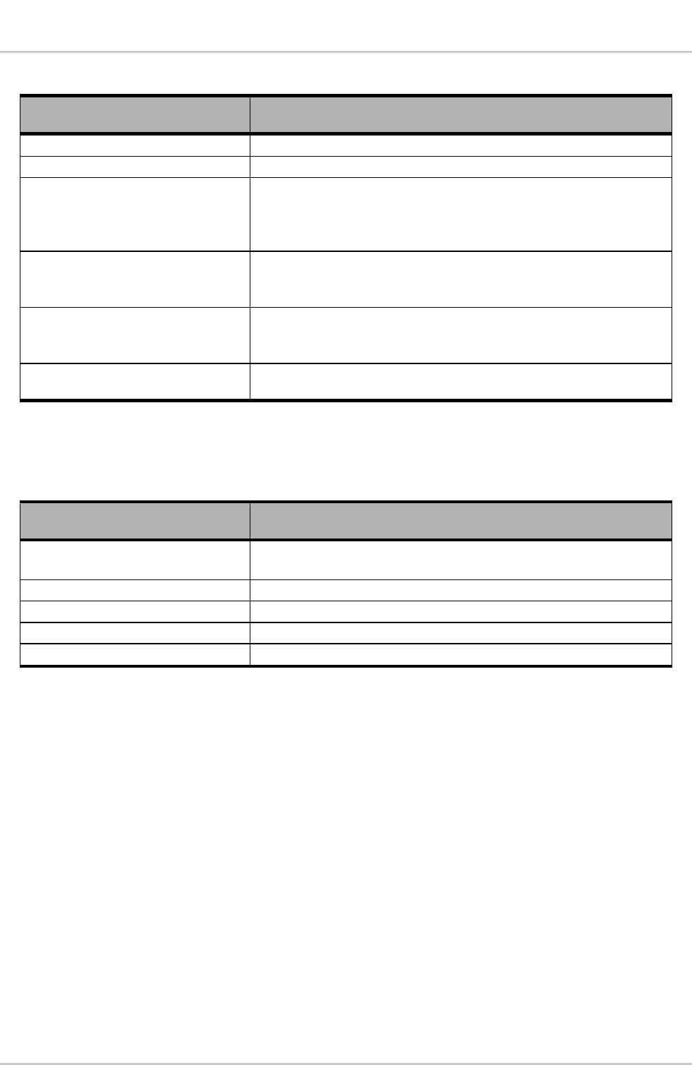
Table 19. GPS Specifications
Parameter/Feature Description
Satellite channels 12 channel, continuous tracking
Protocols NMEA 0183 V3.0
Acquisition time Re-acquisition: 2 sec.
Hot start: 9 sec.
Warm start: 35 sec.
Cold start: 39 sec.
Accuracy Horizontal: < 3 m (50%); < 8 m (90%)
Altitude: < 10 m (50%); < 16 m (90%)
Velocity: 0.06 m/sec.
Sensitivity Acquisition: –158 dBm
Tracking: –160 dBm
Cold-start: –145 dBm
Operational limits Altitude < 18,000 m or velocity: 515 m/sec
(either limit may be exceeded, but not both)
3.2.1. Recommended GPS Antenna Specifications
Table 20. Recommended GPS Antenna Specifications
Parameter/Feature Description
Gain Maximum gain and uniform coverage in high-angle elevation and zenith.
Gain in the azimuth plane is not desired.
Average 3D gain > -5 dBi
VSWR Typical value < 2:1
Isolation (GPS Main) > 10 dB in all related bands
Polarization Any, other than LHCP (left-hand circular polarized)
WA_DEV_SL5011_PTS_001 Rev 001 February 15, 2011 27
4. Mechanical and Environmental
Specifications
Note: After performing the non-operational tests (for example, vibration, shock, and drop), the SL5011
meets all operating parameters.
The SL5011 complies with the mechanical and environmental specifications in this section. Final
product conformance to these specifications depends on the OEM device implementation.
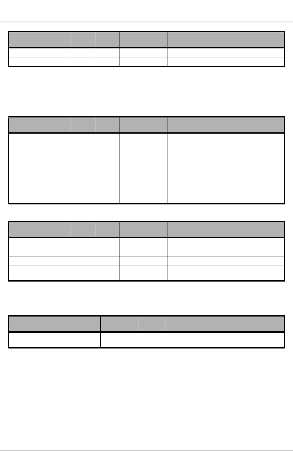
Table 21. Mechanical and Environmental Specifications
Parameter Mode Details
Temperature Operational -30ºC to +70ºC – Full RF compliance
-45°C to +85°C – Function work
+70ºC to +85ºC – Reduced RF performance
Non-operational -40ºC to +85ºC, 96 hours
(from MIL-STD 202 Method 108)
Relative Humidity Non-operational Temperature: 65ºC
Relative humidity (non-condensing): 95%
Test duration: 10 days
Recover time: 1 hour
Ref Std IEC 60068-2-3
DUT op state toggled every 15 minutes (on/off)
Vibration Non-operational Random vibration, 10 to 1000 Hz, nominal
6 G rms in each of three mutually perpendicular axes. Test
duration of 60 minutes for each axis, for a total test time of
three hours.
Shock Non-operational
Half sine shock, 2 ms, 180 in/sec (375 g).
Tested in each of three mutually perpendicular axes, positive
and negative (5 x 6, 30 bumps total).
Drop Non-operational 1 m on concrete on each of 6 faces, 2 times (module only).
Electrostatic discharge Operational The RF port (antenna launch and RF connector) complies
with the IEC 61000-4-2 standard:
Electrostatic Discharge Immunity: Test: Level3
Contact Discharge: ±6 kV
Air Discharge: ±8 kV
Non-operational The host connector Interface complies with the following
standards only
(unless otherwise specified for individual interfaces):
±2 kV Human Body Model (JESD22-A114-B)
±300 V Charged Device Model (JESD22-C101)
Form factor The SL5011 is a 74-pin LGA soldered-down module with a
two-piece shielded case. The device is based on the LGA
Intel Moorestown specification.
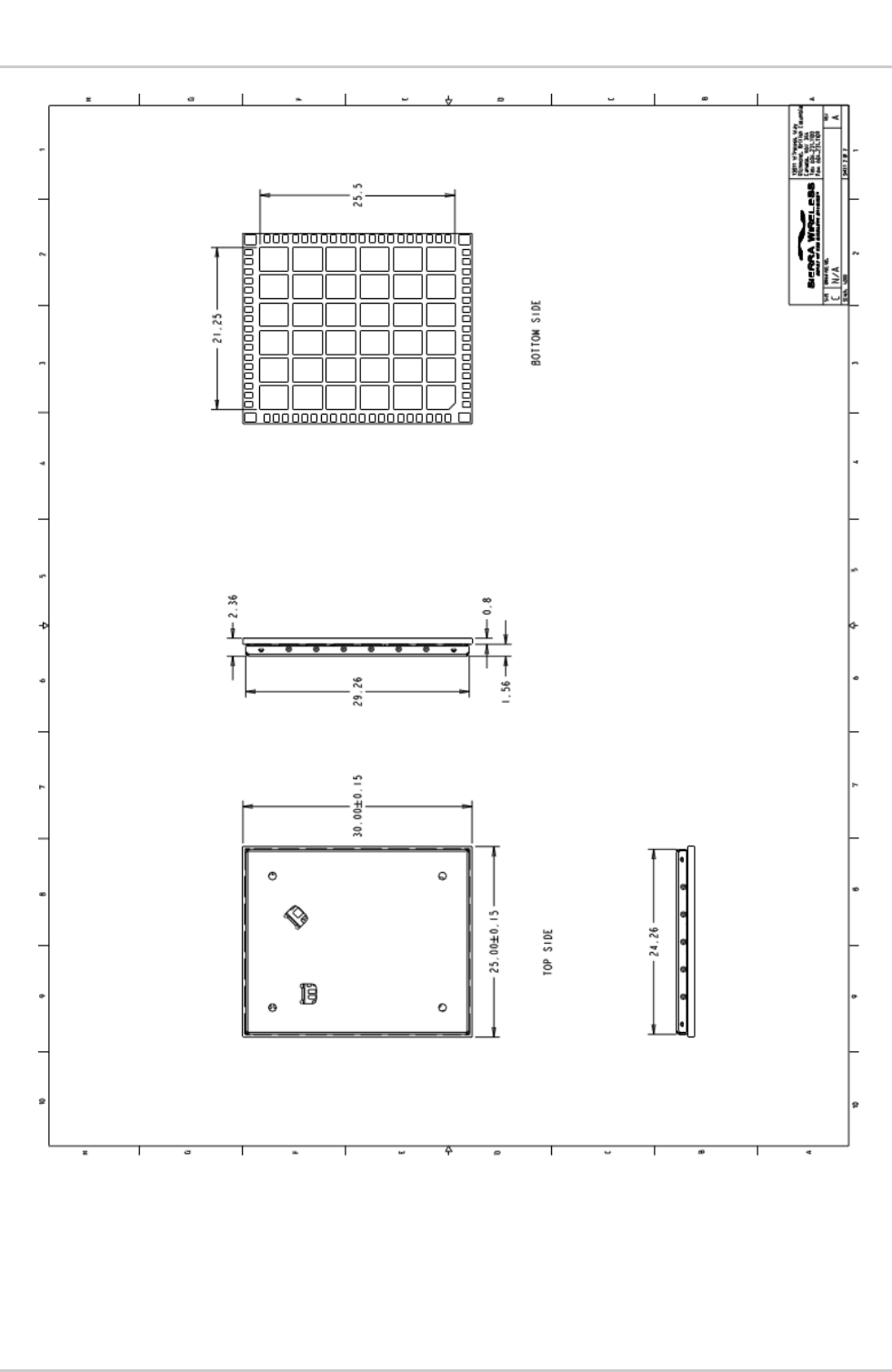
Dimensions Length: 30 mm
Width: 25 mm
Thickness: 2.47 mm
Weight: Approximately 3.5g
WA_DEV_SL5011_PTS_001 Rev 001 February 15, 2011 28
Product Technical Specification &
Customer Design Guidelines
Mechanical and Environmental
Specifications
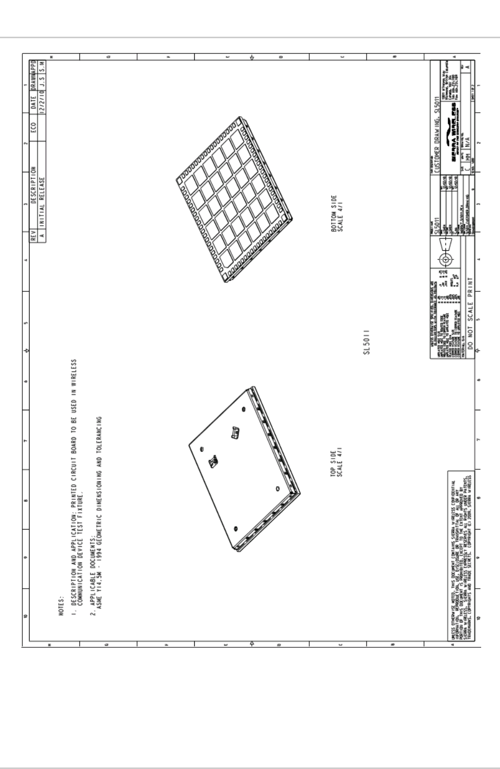
Figure 1. Top and Bottom View (Preliminary)
WA_DEV_SL5011_PTS_001 Rev 001 February 15, 2011 29
Product Technical Specification &
Customer Design Guidelines
Mechanical and Environmental
Specifications
Figure 2. Dimensioned View (Preliminary)
WA_DEV_SL5011_PTS_001 Rev 001 February 15, 2011 30
Product Technical Specification &
Customer Design Guidelines
Mechanical and Environmental
Specifications
4.1. Labeling
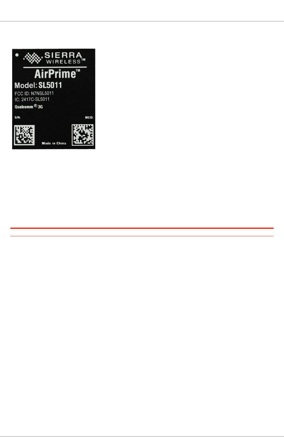
Figure 3. SL5011 Unit Label
The SL5011 label is 28 mm x 23 mm. It is non-removable and contains:
Sierra Wireless logo and product name (SL5011)
SKU number (when required)
Factory Serial Number (FSN) in alphanumeric format (also incorporates the Manufacturing
date code)
IMEI number in Code-128 barcode format
FCC and IC certifications
Note: The SL5011 supports OEM partner specific label requirements.

WA_DEV_SL5011_PTS_001 Rev 001 February 15, 2011 31
5. Regulatory Approval
Important Notice
Because of the nature of wireless communications, transmission and reception of data can
never be guaranteed. Data may be delayed, corrupted (i.e., have errors) or be totally lost.
Although significant delays or losses of data are rare when wireless devices such as the Sierra
Wireless modem are used in a normal manner with a well-constructed network, the Sierra
Wireless modem should not be used in situations where failure to transmit or receive data could
result in damage of any kind to the user or any other party, including but not limited to personal
injury, death, or loss of property. Sierra Wireless and its affiliates accept no responsibility for
damages of any kind resulting from delays or errors in data transmitted or received using Sierra
Wireless modem, or for failure of the Sierra Wireless modem to transmit or receive such data.
Safety and Hazards
Do not operate you SL5011 modem:
In areas where blasting is in progress
Where explosive atmospheres may be present including refueling points, fuel
depots, and chemical plants
Near medical equipment, life support equipment, or any equipment which may be
susceptible to any form of radio interference. In such areas, the SL5011 modem
MUST BE POWERED OFF. Otherwise, the SL5011 modem can transmit
signals that could interfere with this equipment
In an aircraft, the SL5011 modem MUST BE POWERED OFF. Otherwise, the
SL5011 modem can transmit signals that could interfere with various onboard
systems and may be dangerous to the operation of the aircraft or disrupt the
cellular network. Use of cellular phone in aircraft is illegal in some jurisdictions.
Failure to observe this instruction may lead to suspension or denial of cellular
telephone services to the offender, or legal action or both.
Some airlines may permit the use of cellular phones while the aircraft is on the
ground and the door is open. The SL5011 modem may be used normally at this
time.
Important Compliance Information for USA OEM
Integrators
The SL5011 modem is granted with a modular approval for mobile applications. Integrators
may use the SL5011 modem in their final products without additional FCC/IC (Industry Canada)
certification if they meet the following conditions. Otherwise, additional FCC/IC approvals must
be obtained.
1. At least 20cm separation distance between the antenna and the user’s body must be
maintained at all times.
2. To comply with FCC/IC regulations limiting both maximum RF output power and human
exposure to RF radiation, the maximum antenna gain including cable loss in a mobile-
only exposure condition must not exceed 5dBi for Cellular band and 4dBi for CDMA
PCS band.
3. The SL5011 modem and the antenna must not be co-located or operating in
conjunction with any other transmitter or antenna within a host device.
WA_DEV_SL5011_PTS_001 Rev 001 February 15, 2011 32
Product Technical Specification &
Customer Design Guidelines Regulatory Approval
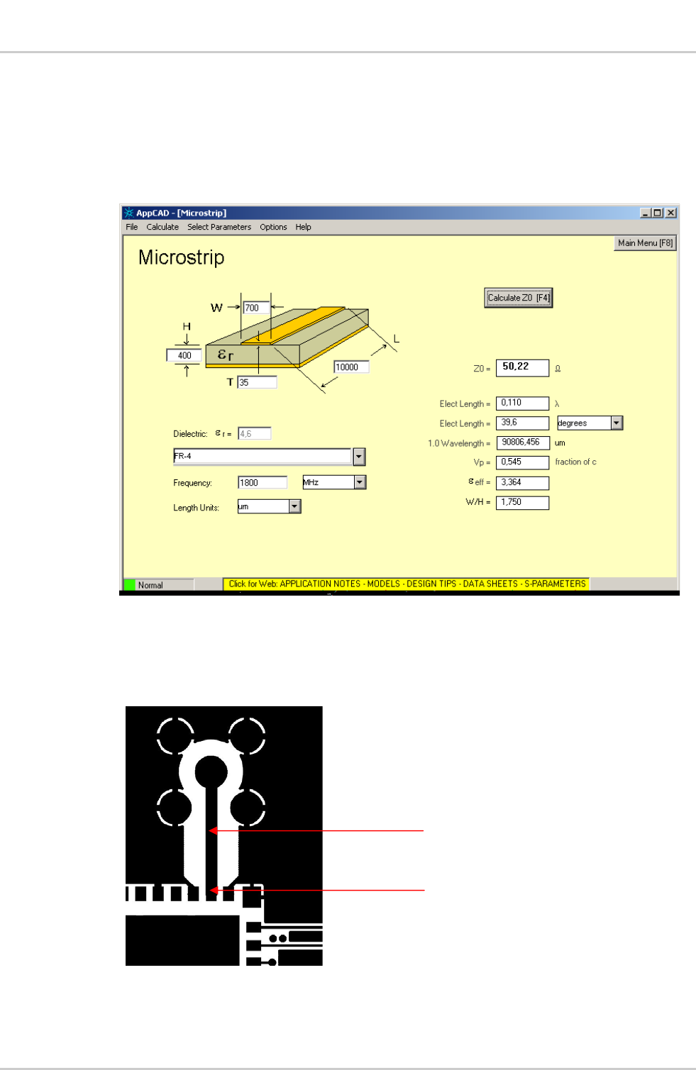
4. The RF signal must be routed on the application board using tracks with a 50
characteristic impedance.
Basically, the characteristic impedance depends on the dielectric, the track width and
the ground plane spacing.
In order to respect this constraint, Sierra Wireless recommends using MicroStrip or
StripLine structure and computing the Tracks width with a simulation tool (like AppCad
shown in the figure below and that is available free of charge at
http://www.agilent.com).
AppCad screenshot for MicroStrip design
If a multi-layered PCB is used, the RF path on the board must not cross any signal
(digital, analog or supply).
If necessary, use StripLine structure and route the digital line(s) "outside" the Fstructure
as shown in the figure below.
Routing examples
Stripline and Coplanar design requires having a correct ground plane at both sides.
Consequently, it is necessary to add some vias along the RF path.
50 line
LGA pin for ANT

WA_DEV_SL5011_PTS_001 Rev 001 February 15, 2011 33
Product Technical Specification &
Customer Design Guidelines Regulatory Approval
It is recommended to use Stripline design if the RF path is fairly long (more than 3cm),
since MicroStrip design is not shielded. Consequently, the RF signal (when
transmitting) may interfere with neighboring electronics (AF amplifier, etc.). In the same
way, the neighboring electronics (micro-controllers, etc.) may degrade the reception
performances.
The CDMA connector is intended to be directly connected to a 50 antenna and no
matching is needed.
5. A label must be affixed to the outside of the end product into which the SL5011 modem
is incorporated, with a statement similar to the following:
This device contains FCC ID: N7NSL5011
Contains transmitter module IC: 2417C-SL5011
where 2417C-SL5011 is the module’s certification number.
A user manual with the end product must clearly indicate the operating requirements and
conditions that must be observed to ensure compliance with current FCC/IC RF exposure
guidelines.
The end product with an embedded SL5011 modem may also need to pass the FCC Part 15
unintentional emission testing requirements and be properly authorized.
Note: If this module is intended for use in a portable device, you are responsible for separate
approval to satisfy the SAR requirements of FCC Part 2.1093 and IC RSS-102.

WA_DEV_SL5011_PTS_001 Rev 001 February 15, 2011 34
6. References
6.1. Standards
6.1.1. TIA/EIA Standards
TIA standards are available at www.tiaonline.org.
[1] TIA/EIA/IS-2000.1 through .6. CDMA2000® Standards for Spread Spectrum Systems.
Release 0. April 2000.
[2] TIA/EIA/IS-2000.1-1 through .6-1. CDMA2000® Addendum 1. April 2000.
[3] TIA/EIA/IS-2000.1-2 through .6-2. CDMA2000® Addendum 2. June 2001.
[4] TIA/EIA-95-B. Mobile Station-Base Station Compatibility Standard for Dual-Mode Spread
Spectrum Systems. December 4, 1998.
[5] TIA/EIA/IS-707-A. Data Service Options for Wideband Spread Spectrum Systems. March
2000.
[6] TIA/EIA/IS-134. Facsimile Digital Interfaces - Amendments to TIA/EIA-592 to Support ITU-T
T.30-1993. October 1994.
[7] TIA/EIA-592. Asynchronous Facsimile DCE Control Standard - Service Class 2. April 1998.
[8] TIA/EIA-617. Data Transmission Systems and Equipment for In-Band DCE Control.
January 1996.
[9] TIA/EIA/IS-733-1. High Rate Speech Service Option 17 for Wideband Spread Spectrum
Communication Systems. September 1999.
[10] TIA/EIA/IS-736. Recommended Minimum Performance Standard for the High Rate Speech
Service Option 17 for Spread Spectrum Communication Systems. August 2000.
[11] TIA/EIA/IS-127-2. Enhanced Variable Rate Codec, Speech Service Option 3 for Wideband
Spread Spectrum Digital Systems - Addendum 2. September 1999.
[12] TIA/EIA/IS-718. Minimum Performance Specification for the Enhanced Variable Rate
Codec, Speech Service Option 3 for Spread Spectrum Digital Systems. July 1998.
[13] TIA/EIA-637-B. Short Message Service for Wideband Spread Spectrum Cellular Systems.
January 2002.
[14] TIA/EIA/IS-683-A. Over-the-Air Service Provisioning of Mobile Stations in Spread Spectrum
Systems. June 1998.
[15] TIA/EIA/IS-835-A. Wireless IP Network Standard. May 2001.
[16] TIA/EIA/IS-870. Test Data Service Option (TDSO) for CDMA2000® Spread Spectrum
Systems. 2001.
[17] TIA/EIA/IS-98D/E. Recommended Minimum Performance Standards for Dual-Mode Spread
Spectrum Mobile Stations.
[18] TIA/EIA/IS-866. Recommended Minimum Performance Standards for CDMA2000® High
Rate Packet Data Access Terminal.
[19] TIA/EIA-126-D. Mobile Station Loop back Service Options Standard. 2001.
[20] TIA/EIA TSB 58-C. Administration of Parameter Value Assignments for TIA/EIA Wideband
Spread Spectrum Standards. May 2000.
[21] TIA/EIA TSB 50. User Interface for Authentication Key Entry. March 1993.

WA_DEV_SL5011_PTS_001 Rev 001 February 15, 2011 35
Product Technical Specification &
Customer Design Guidelines References
[22] TIA/EIA/IS-801.1. Location Service Standard for Dual-Mode Spread Spectrum Systems.
March 2001.
[23] C.S0031-0. Signaling Conformance Tests for CDMA2000® Spread Spectrum Systems,
Ballot Resolution. Version 3GPP2 TSG- C v2.0
[24] C.S0036-0. Recommended Minimum Performance Specification for C.S0022-0 Spread
Spectrum Mobile Stations. 3GPP2 C.S0036-0 v1.0.
[25] TIA/EIA/IS-J-STD-036. Enhanced Wireless 9-1-1 Phase II. January 2001.
[26] TIA/EIA/IS-856. CDMA2000® High Rate Packet Data Air Interface Specification. November
2000.
6.1.2. CDG Standards
[27] CDG 22. Stage 2 Interoperability Tests (TIA/EIA/IS-95A). Ver. 8.0. September 2000.
[28] CDG 53. Stage 2 Interoperability Tests (TIA/EIA/95B). Ver. 2.0. June 2000.
[29] CDG 57. Stage 2 Interoperability Tests (TIA/EIA/IS-2000). Ver. 0.7. February 2001.
[30] CDG 36. Markov Service Options for Wideband Spread Spectrum Systems
Communications Systems. March 11, 1996.
[31] CDG 64. CDG Stage 3 Testing for CDMA2000®. Ver. 1.0. August 2002.
6.1.3. Agency Standards
[32] FCC 47 CFR - Part 15. Radio Frequency Devices. January 2001.
[33] FCC 47 CFR - Part 22. Cellular Radiotelephone Services. October 1998.
[34] FCC 47 CFR - Part 24. Personal Communications Services. October 1998.
[35] Industry Canada ICES-003. Interference-Causing Equipment Standard - Digital Apparatus.
November 22, 1997.
[36] Industry Canada RSS-132. Cellular Telephones Employing New Technologies Operating in
the Bands 824-849 MHz and 869-894 MHz. Issue 2. September 2005.
[37] Industry Canada RSS-133. 2 GHz Personal Communications Services. September 25,
1999.
[38] IEC 61000-4-2. Electrostatic Discharge Immunity Test.
[39] JESD22-A114-B. +/- 1 kV Human Body Model.
[40] JESD22-C101. +/- 125 V Charged Device Model.
[41] FCC 47 CFR - Part 2. Frequency allocations and radio treaty matters; general rules and
regulations.
6.1.4. Other Standards
[42] Openwave_IOTA_Protocol_v2.0_Specifications_doc_v2.04. February 2002.
[43] Universal Serial Bus Specification. Revision 2.0. www.usb.org/developers/docs.

WA_DEV_SL5011_PTS_001 Rev 001 February 15, 2011 36
Product Technical Specification &
Customer Design Guidelines References
6.2. Sierra Wireless Documentation
[44] EMConnect Guide
Reference: 2131177
[45] Hardware Integration Guide
Reference: 2130114
[46] AT Command Reference Guide
Reference: 2130620
[47] CnS Reference
Reference: 2130754

WA_DEV_SL5011_PTS_001 Rev 001 February 15, 2011 37
7. Acronyms
Table 22. Acronyms
Acronym or Term Definition
1xEV-DO Single Carrier (1X) EVolution – Data Only. A high-speed standard for cellular packet
data communications.
Supports Internet connections with data rates up to 3.1 Mbps (downlink from the
network) and 1.8 Mbps (uplink to the network). Average data rates are roughly: for Rev.
A: 600-1300 kbps (downlink from the network) and 300-400 kbps (uplink to the
network); for Rev. 0: 400-700 kbps (downlink from the network) and 40-80 kbps (uplink
to the network). Actual speed depends on the network conditions. Compare to 1X.
1X Single Carrier (1X) Radio Transmission Technology. A high-speed standard for cellular
packet data communications.
Supports Internet connections with data rates up to 153 kbps (simultaneously in each
direction—downlink and uplink). Actual speed depends on the network conditions.
Compare to 1xEV-DO.
API Application Programming Interface
AT A set of modem commands, preceded by “AT,” originally developed by Hayes, Inc. for
their modems. The structure (but not the specific commands, which vary greatly from
manufacturer to manufacturer) is a de facto modem industry standard.
CDG CDMA Development Group
CDMA Code Division Multiple Access.
A wideband spread spectrum technique used in digital cellular, personal
communications services, and other wireless networks. Wide channels (1.25 MHz) are
obtained through spread spectrum transmissions, thus allowing many active users to
share the same channel. Each user is assigned a unique digital code, which
differentiates the individual conversations on the same channel.
CDMAOne The IS-95 CDMA standard developed by QUALCOMM Inc.
CnS Sierra Wireless proprietary Control and Status language interface
DCE Data Communications Equipment
EIA Electronics Industry Association
ERP Effective Radiated Power
ESN Electronic Serial Number—The unique first-generation serial number assigned to the
SL5011 for use on the wireless network. Compare to MEID.
FCC Federal Communications Commission.
The U.S. federal agency that is responsible for interstate and foreign communications.
The FCC regulates commercial and private radio spectrum management, sets rates for
communications services, determines standards for equipment, and controls broadcast
licensing. Consult www.fcc.gov.
firmware Software stored in ROM or EEPROM; essential programs that remain even when the
system is turned off. Firmware is easier to change than hardware but more permanent
than software stored on disk.
FSN Factory Serial Number—A unique serial number assigned to the SL5011 during
manufacturing.
GPS Global Positioning System
A system that uses a series of 24 geosynchronous satellites to provide navigational
data.
IOTA Internet Over The Air—an automated feature, supported by some service providers, to
perform account setup for you by making a connection to the CDMA network and using
a secure Internet connection to download account parameters to your device.
IS Interim Standard.
After receiving industry consensus, the TIA forwards the standard to ANSI for approval.

WA_DEV_SL5011_PTS_001 Rev 001 February 15, 2011 38
Product Technical Specification &
Customer Design Guidelines Acronyms
Acronym or Term Definition
kbps kilobits per second – Actually 1000, not 1024, as used in computer memory size
measurements of kilobytes.
LED Light Emitting Diode.
A semiconductor diode that emits visible or infrared light.
Mbps Millions of bits per second, or Megabits per second.
MEID Mobile Equipment IDentifier—The unique second-generation serial number assigned to
the SL5011 for use on the wireless network. Compare to ESN.
NAM Number Assignment Module
Semi-permanent information stored in the modem’s non-volatile memory, including the
modem’s Mobile Identification Number, the station class mark, carrier code, and other
cellular identifiers. Essentially the phone number, it should be treated as confidential
information and should not be disclosed to anyone other than the cellular service
provider.
NV Non-Volatile (memory)
OEM Original Equipment Manufacturer
A company that manufactures a product and sells it to a reseller.
OTAPA Over the Air Parameter Administration
OTASP Over the Air Service Provisioning
PCS Personal Communications Services
A cellular communication infrastructure that uses a different frequency range than
AMPS.
PPP Point to Point Protocol.
An alternative communications protocol used between computers, or between
computers and routers on the Internet. PPP is an enhanced SLIP.
PRI Product Release Instructions—a file that contains the settings used to configure
modems for a particular service provider, customer, or purpose.
QAM Quadrature Amplitude Modulation.
This form of modulation uses amplitude, frequency, and phase to transfer data on the
carrier wave.
RF Radio Frequency
RLP Radio Link Protocol.
This protocol improves the error characteristics of the wireless link, thereby reducing the
need for transport layer retransmission due to lost data.
Rx Receive
SAR Specific Absorption Rate
SKU Stock Keeping Unit—identifies an inventory item: a unique code, consisting of numbers
or letters and numbers, assigned to a product by a retailer for purposes of identification
and inventory control.
SMS Short Message Service.
A feature that allows users of a wireless device on a wireless network to receive or
transmit short electronic alphanumeric messages (up to 160 characters, depending on
the service provider).
TIA/EIA Telecommunications Industry Association / Electronics Industry Association.
Telecommunications Industry Association – A standards setting trade organization,
whose members provide communications and information technology products,
systems, distribution services and professional services in the United States and around
the world. Consult www.tiaonline.org.
Tx Transmit
USB Universal Serial Bus