Sierra Wireless SL6087 Module User Manual
Sierra Wireless Inc. Module Users Manual
UserManual.wiki
>
Sierra Wireless
>
SL6087 User Manual
Users Manual
Navigation menu
Upload a User Manual
Namespaces
Wiki Guide
HTML
PDF
Info
Views
User Manual
Discussion / Help
Navigation
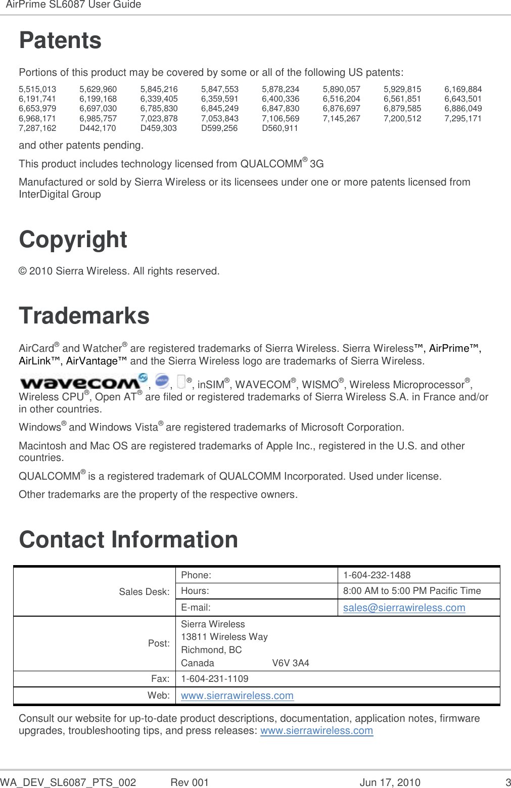
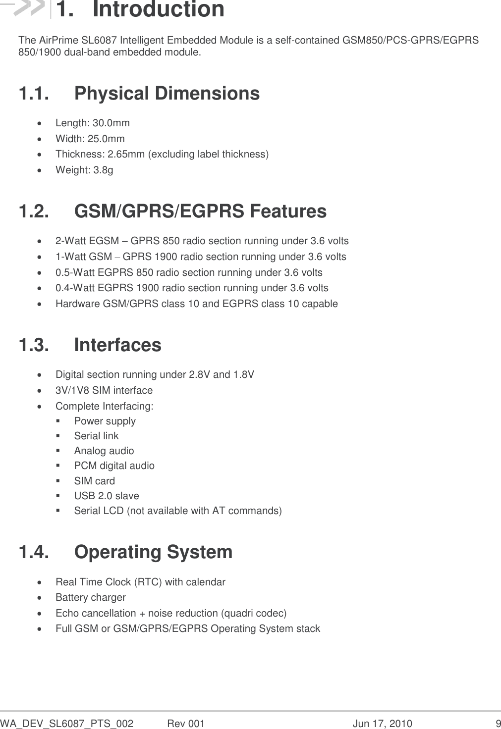
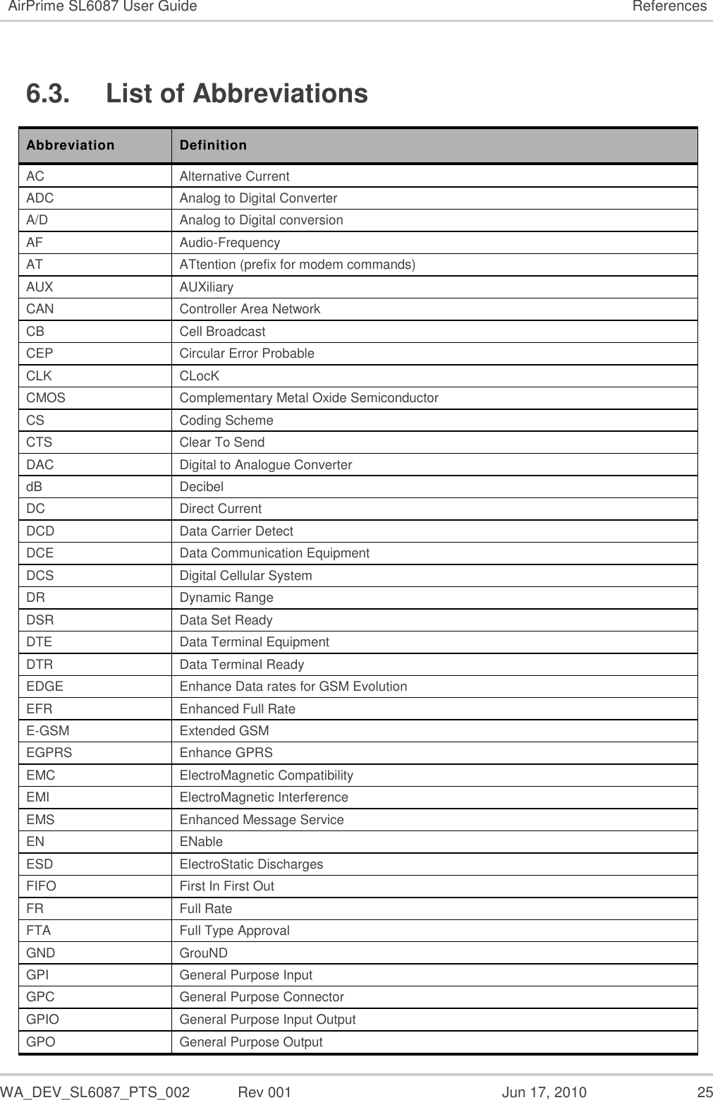
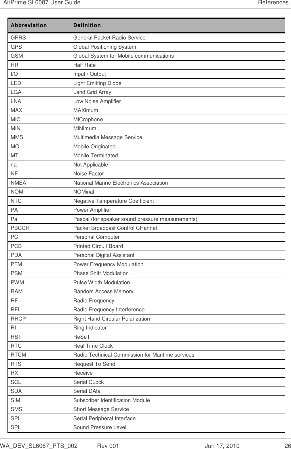
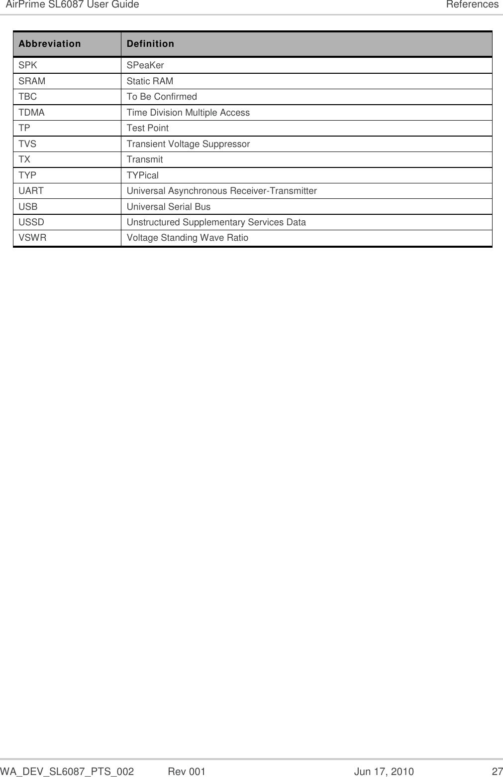
![WA_DEV_SL6087_PTS_002 Rev 001 Jun 17, 2010 22 6. References 6.1. Web Site Support Check the Sierra Wireless website at http://sierrawireless.com for the latest documentation available. Content Web Site General information about AirPrime SL Series Intelligent Embedded Module http://www.sierrawireless.com/en/productsandservices/AirPrime/Embedded_Modules/SL_Series.aspx Specific support about the AirPrime SL6087 Embedded Module http://www.sierrawireless.com/productsandservices/AirPrime/Embedded_Modules/SL_Series/SL_6087.aspx Carrier/Operator approvals http://www.sierrawireless.com/en/sitecore/content/Sierra%20Wireless/Support/Downloads/AirPrime/SL_Series/AirPrime_SL6087.aspx Sierra Wireless Software Suite Introduction http://www.sierrawireless.com/productsandservices/AirPrime/Sierra_Wireless_Software_Suite/Open_AT_Operating_System.aspx Developer support for software and hardware http://forum.sierrawireless.com/ 6.2. Reference Documents For more details, several reference documents can be consulted. The Sierra Wireless documents referenced herein are provided in the Sierra Wireless documentation package; however, the general reference documents which are not Sierra Wireless owned are not provided in the documentation package. 6.2.1. Sierra Wireless Software Documentation [1] Getting started with SDK 4.22b Reference: WM_DEV_OAT_UGD_048 [2] Tutorial for IDE 1.08 (if using IDE; obsolete if using Developer Studio) Reference: WM_DEV_OAT_UGD_044 [3] Tools Manual for IDE 1.08 (if using IDE; obsolete if using Developer Studio) Reference: WM_DEV_OAT_UGD_045 [4] Basic Development Guide for SDK 4.22 (if using IDE; obsolete if using Developer Studio) Reference: WM_DEV_OAT_UGD_050 [5] ADL User Guide for SDK 4.22 (if using IDE; obsolete if using Developer Studio) Reference: WM_DEV_OAT_UGD_051 [6] SDK 4.22 Official Release Note Reference: WM_DEV_OAT_DVD_338](https://usermanual.wiki/Sierra-Wireless/SL6087/User-Guide-1298916-Page-22.png)
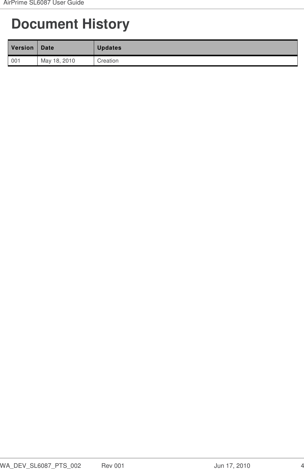
![WA_DEV_SL6087_PTS_002 Rev 001 Jun 17, 2010 23 AirPrime SL6087 User Guide References 6.2.2. Firmware Documentation [7] Firmware 7.4b AT Commands Manual (Sierra Wireless Software Suite 2.32) Reference: WM_DEV_OAT_UGD_079 (Version 14) [8] AT Commands Interface Guide Reference: WM_DEV_OAT_UGD_014 [9] AT Commands Interface Guide (Bluetooth) Reference: WM_ASW_BLU_UGD_001 [10] Firmware 7.4 Customer Release Note Reference: TBC 6.2.3. Hardware Documentation [11] AirPrime Q2687 Classic Product Technical Specification Reference: WM_DEV_Q2687_PTS_001 [12] AirPrime Q26xx Process Customer Guidelines Reference: WM_PRJ_Q2686_PTS_004 [13] AirPrime Q2687 Customer Design Guidelines Reference: WA_DEV_Q2687_PTS_007 [14] AirPrime Q2687 Product Technical Specification Reference: WA_ENG_Q2687_PTS_001 [15] AirPrime Q Series Development Kit User Guide Reference: WM_BBD_Q26_UGD_001 [16] AirPrime Q2687 Refreshed Migration Guide Reference: WA_DEV_Q26RD_UGD_001 [17] AirPrime Q2686 Product Technical Specification Reference: WM_PRJ_Q2686_PTS_001 [18] AirPrime Q2687 Refreshed Product Technical Specification and Customer Design Guideline Reference: WA_DEV_Q26RD_PTS_001 [19] AirPrime SL Series Development Kit User Guide Reference: WA_DEV_SL6087_UGD_003 [20] Customer Process Guideline for AirPrime SL6087 Reference: WM_DEV_SL6087_PTS_001 [21] AirPrime SL6087 Migration Guide Reference: WA_DEV_SL6087_UGD_001](https://usermanual.wiki/Sierra-Wireless/SL6087/User-Guide-1298916-Page-23.png)
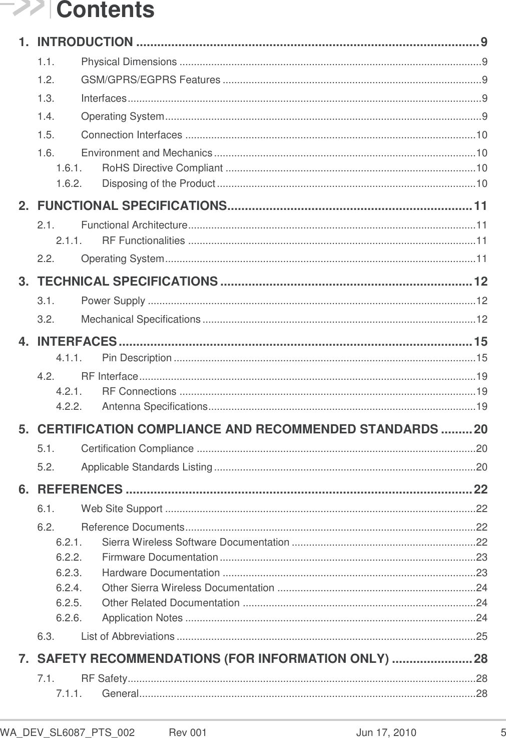
![WA_DEV_SL6087_PTS_002 Rev 001 Jun 17, 2010 24 AirPrime SL6087 User Guide References 6.2.4. Other Sierra Wireless Documentation [22] Automotive Environmental Control Plan for SL6087 Embedded Module Reference: WM_QUA_Q2687_DCP_001 [23] Bluetooth Interface Application Note Reference: WM_ASW_OAT_APN_016 6.2.5. Other Related Documentation [24] “I2C Bus Specification”, Version 2.0, Philips Semiconductor 1998 [25] ISO 7816-3 Standard 6.2.6. Application Notes For other application notes, the following reference designs are available upon request to Sierra Wireless support. Title Description Power Supply with automotive constraints DC-DC converter based on STMicroElectronics L5973AD VIN = 5.5...32V VOUT = 3.8V Especially designed to meet Sierra Wireless Intelligent Embedded Module requirements. CAN Interface (high speed) CAN Interface over SPI based on: - MicroChip MCP2515 CAN Controller, - Philips PCA82C250T CAN Transceiver. CAN Interface (low speed) CAN Interface (over SPI) based on: - MicroChip MCP2515 CAN Controller, - Philips TJA1054A CAN Transceiver. Bluetooth Connection Provides BlueTooth Connectivity (over UART2) based on: Murata LBMA29BAE2 HCI BlueTooth module. Dual USB Interface Provides 2 separate serial ports on a USB interface, based on: FTDI FTDI2232C Dual USB UART with FIFO Power Supply on USB VIN = 5.0V (from USB supply) VOUT = 3.8V Especially designed to meet Sierra Wireless Intelligent Embedded Module and power supply requirements. Full GSM-GPRS modem on USB Based on the two previous designs](https://usermanual.wiki/Sierra-Wireless/SL6087/User-Guide-1298916-Page-24.png)