Sierra Wireless SL8090 Wireless Module User Manual Hdw Integration Manual
Sierra Wireless Inc. Wireless Module Hdw Integration Manual
UserManual.wiki
>
Sierra Wireless
>
SL8090 User Manual
Hdw Integration Manual
Navigation menu
Upload a User Manual
Namespaces
Wiki Guide
HTML
PDF
Info
Views
User Manual
Discussion / Help
Navigation
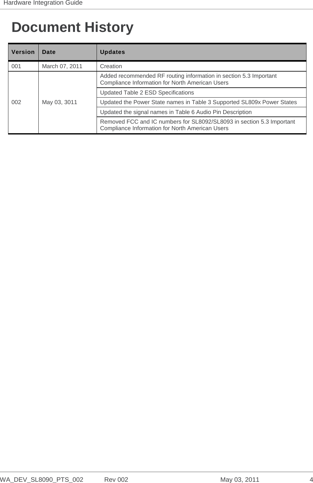
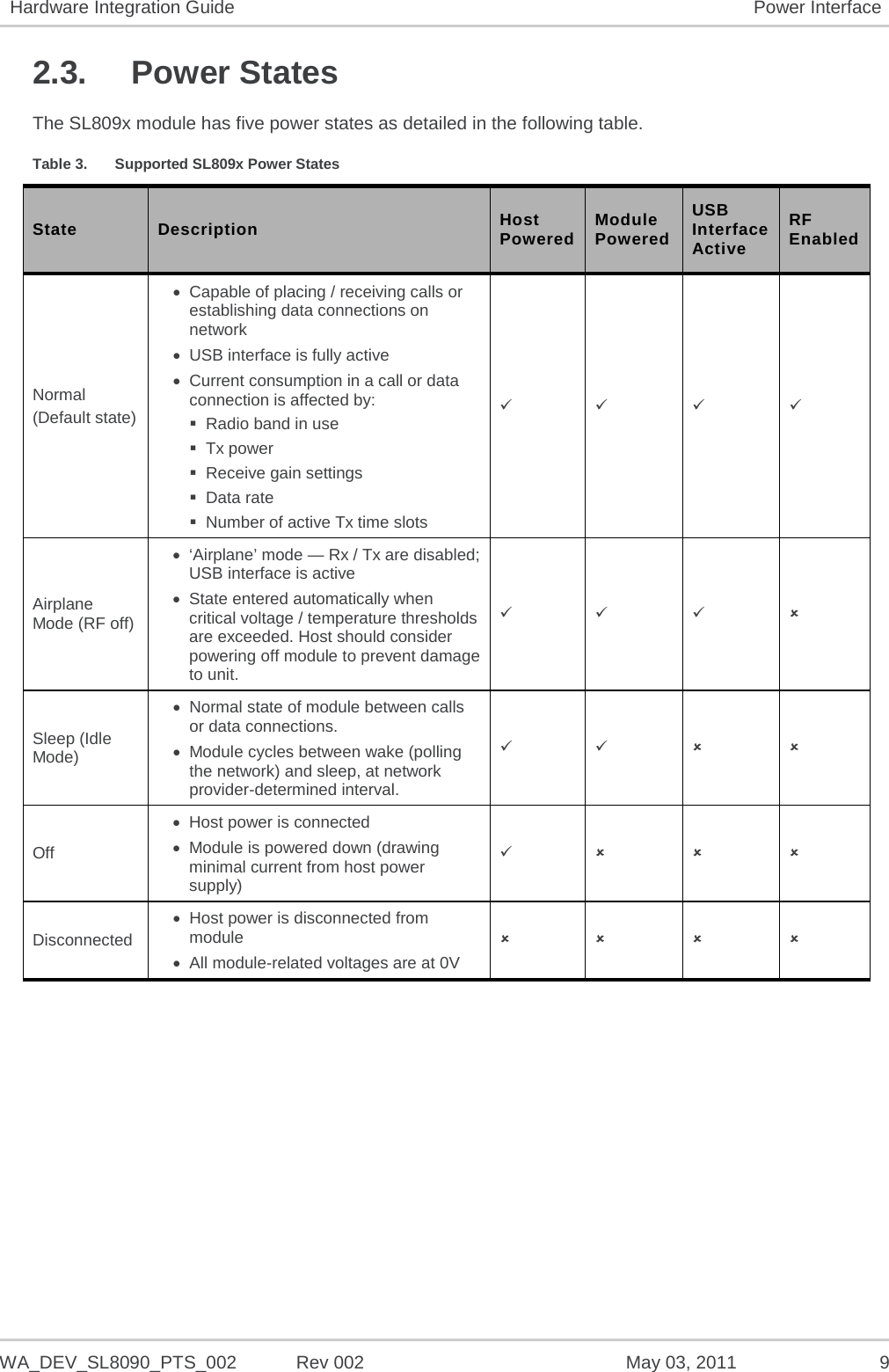
![WA_DEV_SL8090_PTS_002 Rev 002 May 03, 2011 7 1. Introduction The Sierra Wireless AirPrime SL809x soldered-down module forms the radio component for the products in which it is embedded. Module-specific performance and physical characteristics are described in the corresponding product specification document. Note: An understanding of network technology, and experience in integrating hardware components into electronic equipment is assumed. 1.1. Hardware Development Components Sierra Wireless manufactures two hardware development components to facilitate the hardware integration process: • AirPrime SL Socket Board – Adapter board on which an SL module is embedded. This board may be used as a stand-alone platform for basic hardware development. • AirPrime SL Development Kit – Hardware development board on which an SL socket board is plugged. The development kit provides access to all of the interfaces supported by the SL module. For instructions on using the SL Development Kit, see document [1] Universal Development Kit User Guide for AirPrime SL Series.](https://usermanual.wiki/Sierra-Wireless/SL8090/User-Guide-1464813-Page-7.png)
![WA_DEV_SL8090_PTS_002 Rev 002 May 03, 2011 13 4. Audio Interface The AirPrime SL809x embedded module only supports digital audio interface (PCM) as summarized in the following tables. Refer to document [2] AirPrime SL8090/SL8091 Product Technical Specification and Customer Design Guidelines for detailed information about the digital audio interface. Table 5. PCM Audio Interface Features Feature Details Implementation Primary PCM supported to interface with external codec Power 1.8 V (use VREF_1V8 as logic reference) Features • IOM-2 compatible device on physical level • Master mode only with 6 slots by frame (user only on slot 0) • Bit rate single clock mode at 2.048 MHz • 16 bits data word MSB first only • Linear Law only (no compression law) • Long Frame Synchronization only • Push-pull configuration on PCM-OUT and PCM-IN Table 6. Audio Pin Description Pin # Signal Name Description Notes 64 PCM_SYNC PCM synchronization bit 8 kHz 65 PCM_DOUT PCM output 66 PCM_DIN PCM input 67 PCM_CLK PCM clock 2 MHz for primary PCM mode](https://usermanual.wiki/Sierra-Wireless/SL8090/User-Guide-1464813-Page-13.png)
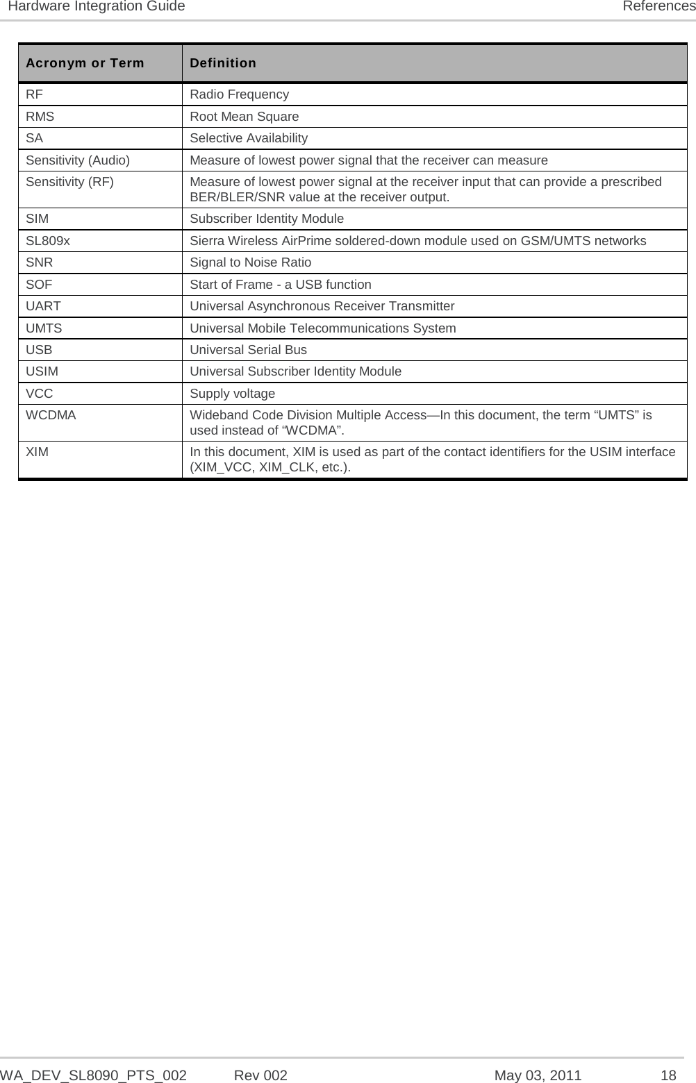
![WA_DEV_SL8090_PTS_002 Rev 002 May 03, 2011 17 6. References 6.1. Reference Documents [1] Universal Development Kit User Guide for AirPrime SL Series Reference: WA_DEV_SL6087_UGD_003 [2] AirPrime SL8090/SL8091 Product Technical Specification and Customer Design Guidelines Reference: WA_DEV_SL8090_PTS_001 6.2. List of Abbreviations Acronym or Term Definition AGC Automatic Gain Control BER Bit Error Rate - a measure of receive sensitivity BLER Block Error Rate Call Box Base Station Simulator - Agilent E8285A or 8960, Rohde & Schwarz CMU200 CDMA Code Division Multiple Access dB Decibel = 10 x log10 (P1/P2) P1 is calculated power; P2 is reference power Decibel = 20 x log10 (V1/V2) V1 is calculated voltage, V2 is reference voltage dBm Decibels, relative to 1 mW - Decibel(mW) = 10 x log10 (Pwr (mW)/1mW) DUT Device Under Test EDGE Enhanced Data rates for GSM Evolution EM Embedded Module ESD ElectroStatic Discharge FER Frame Error Rate - a measure of receive sensitivity GPRS General Packet Radio Services GPS Global Positioning System GSM Global System for Mobile communications Hz Hertz = 1 cycle/second inrush current Peak current drawn when a device is connected or powered on IS-2000 3G radio standards for voice and data (CDMA only) IS-95 2G radio standards targeted for voice (cdmaONE) LDO Low Drop Out - refers to linear regulator MHz MegaHertz = 10E6 Hertz (Hertz = 1 cycle/second) MIO Module Input/Output MPE Maximum Permissible Exposure—the level of radiation to which a person may be exposed without hazardous effect or adverse biological changes OTA Over-The-Air or Radiated through the antenna PCS Personal Communication System - PCS spans the 1.9 GHz radio spectrum](https://usermanual.wiki/Sierra-Wireless/SL8090/User-Guide-1464813-Page-17.png)