Sierra Wireless SXL1-P WIRELESS PROGRAMMER User Manual SXL1 Users Manual 11 11 10
Numerex Corporation WIRELESS PROGRAMMER SXL1 Users Manual 11 11 10
UserManual.wiki
>
Sierra Wireless
>
SXL1 P User Manual
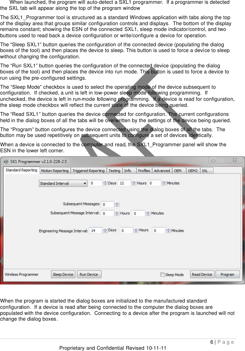
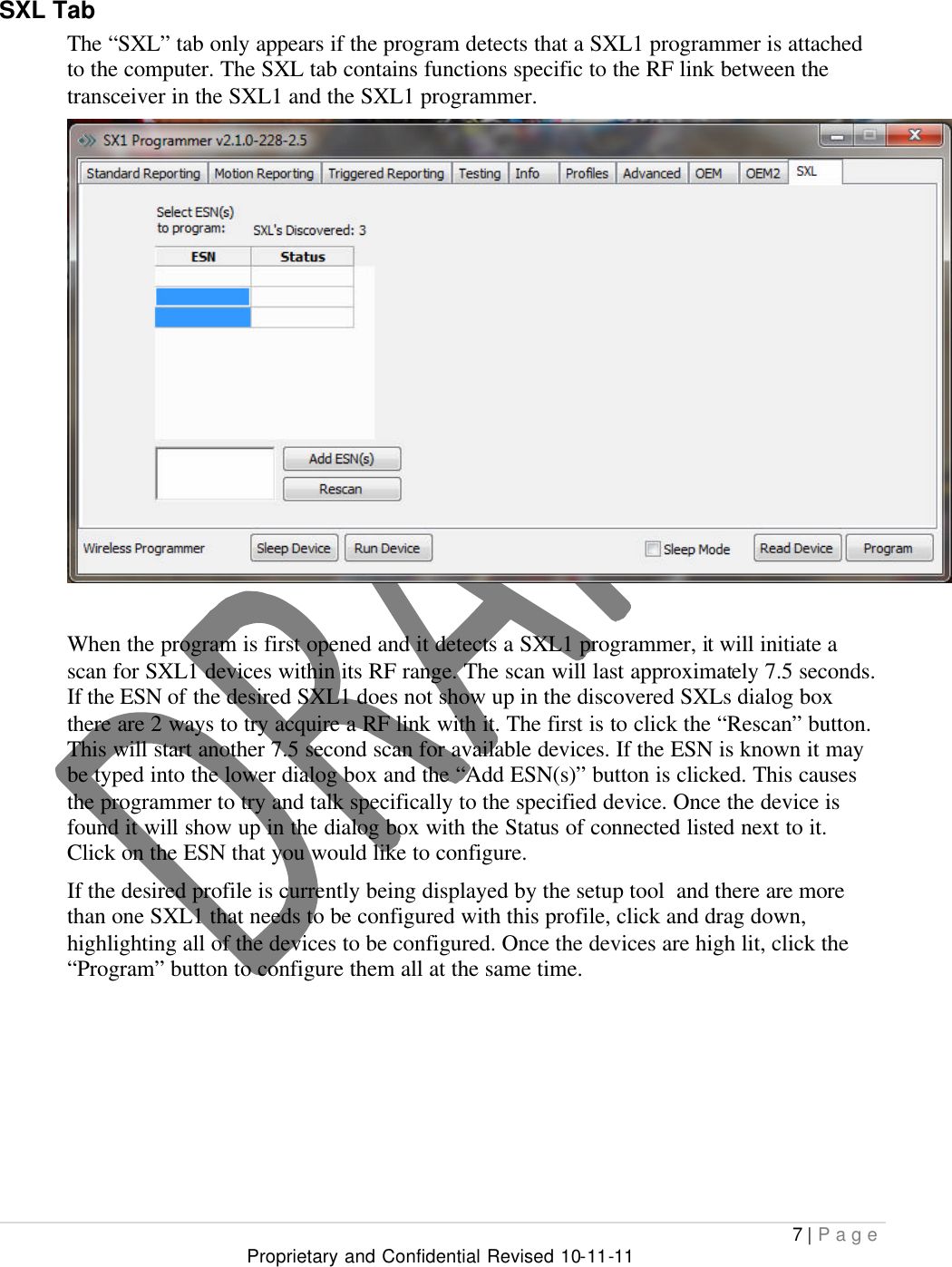
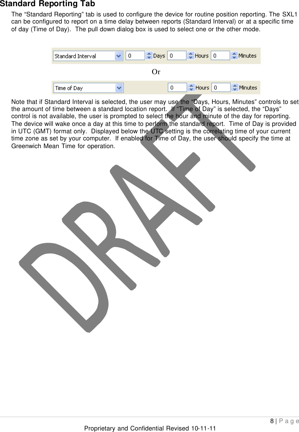
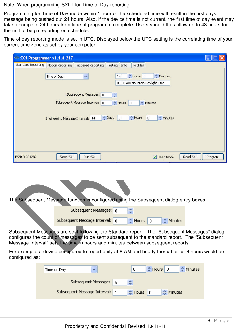
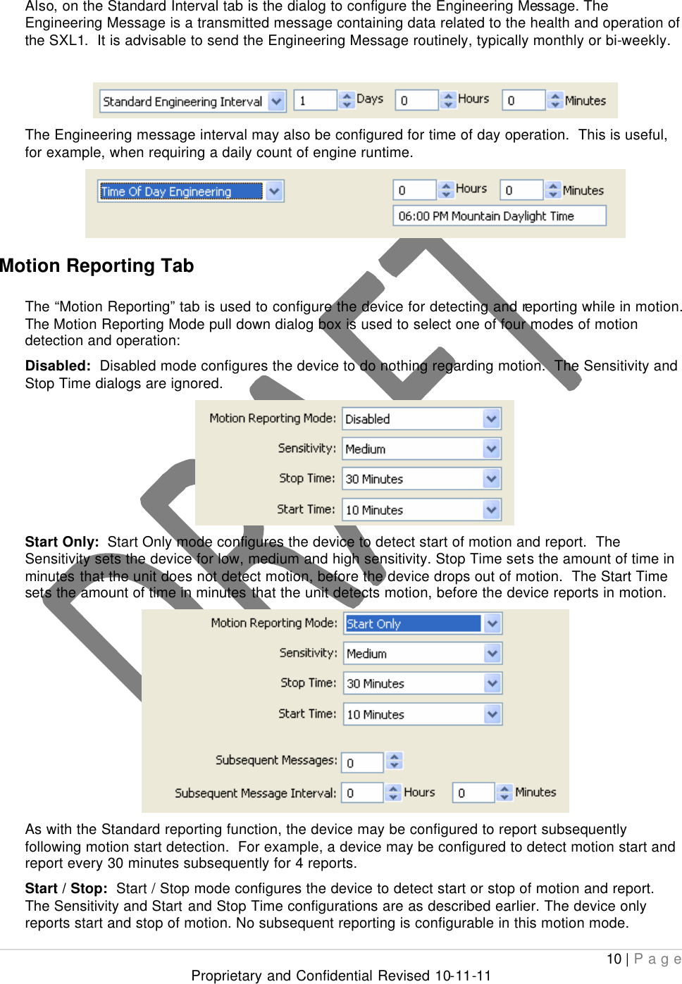
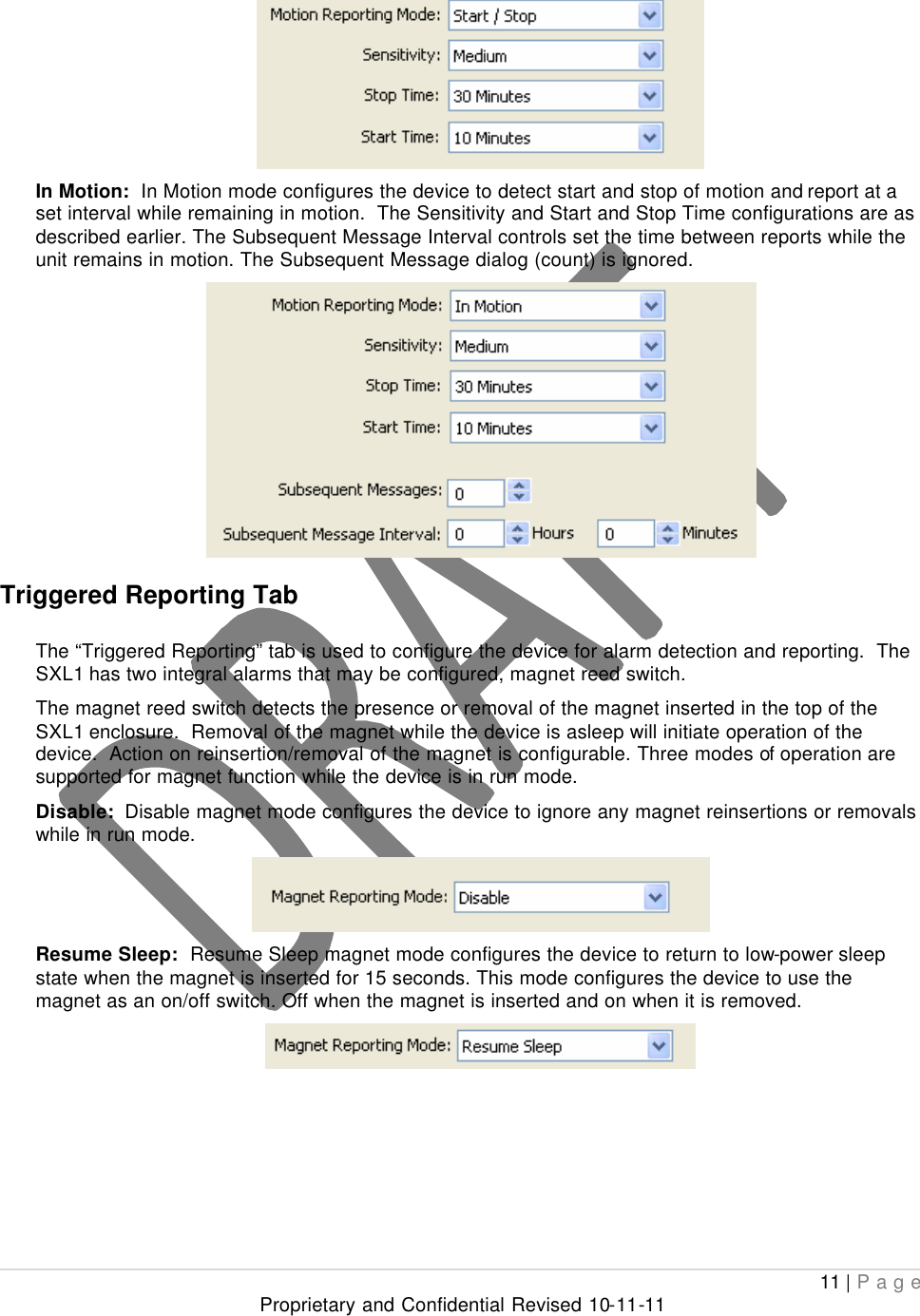
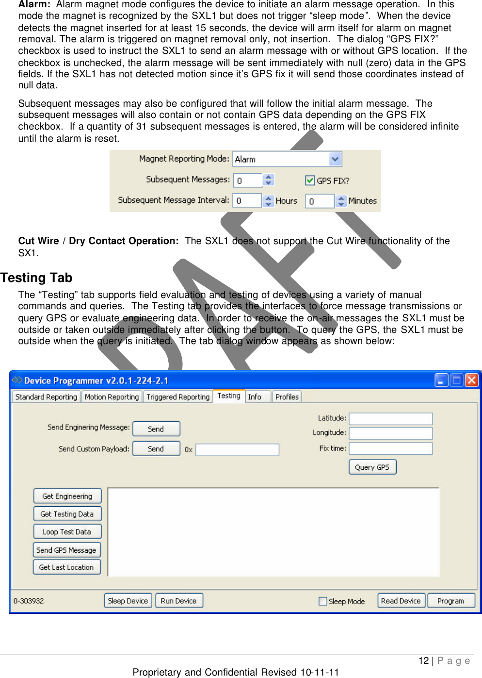
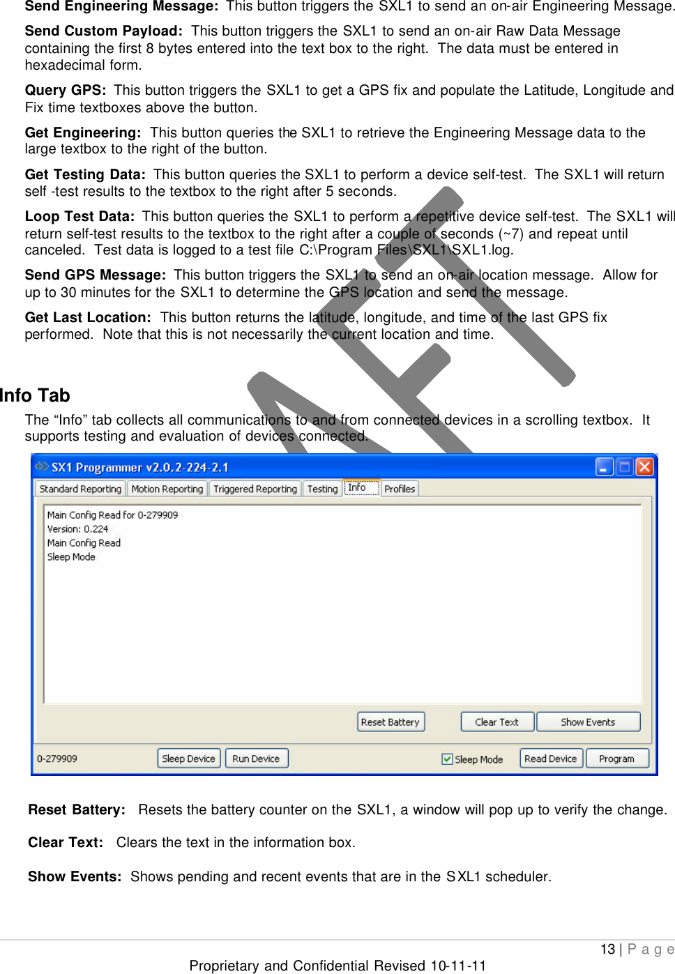
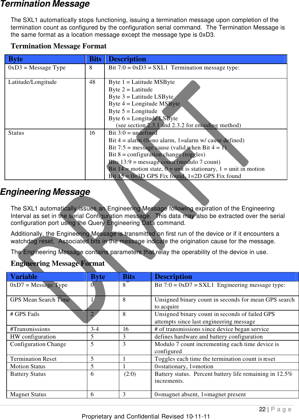
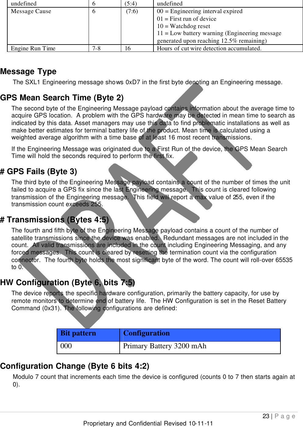
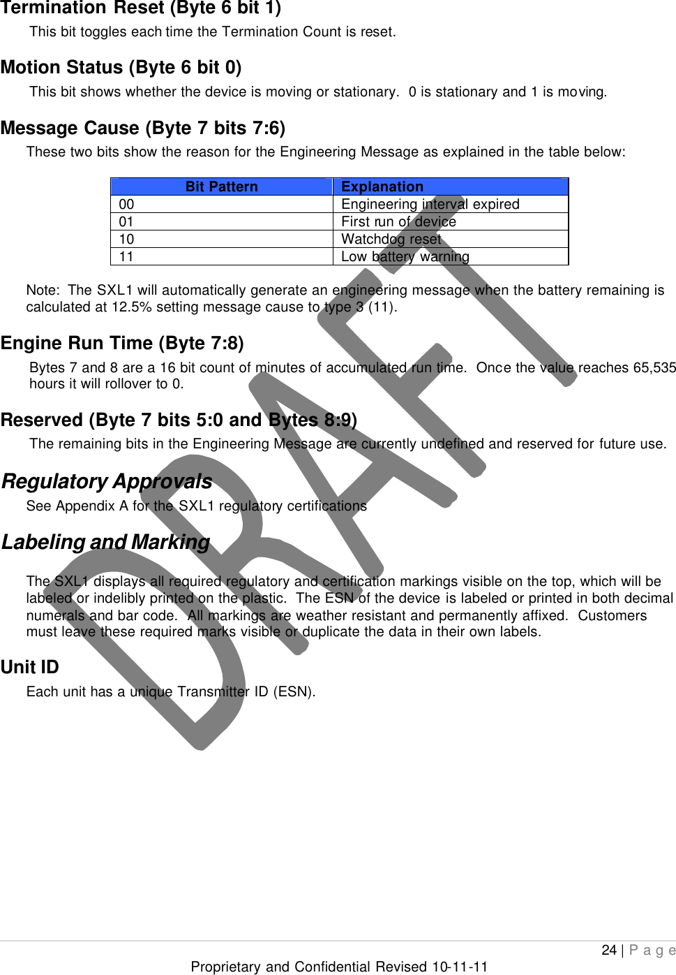
Users Manual
Navigation menu
Upload a User Manual
Namespaces
Wiki Guide
HTML
PDF
Info
Views
User Manual
Discussion / Help
Navigation