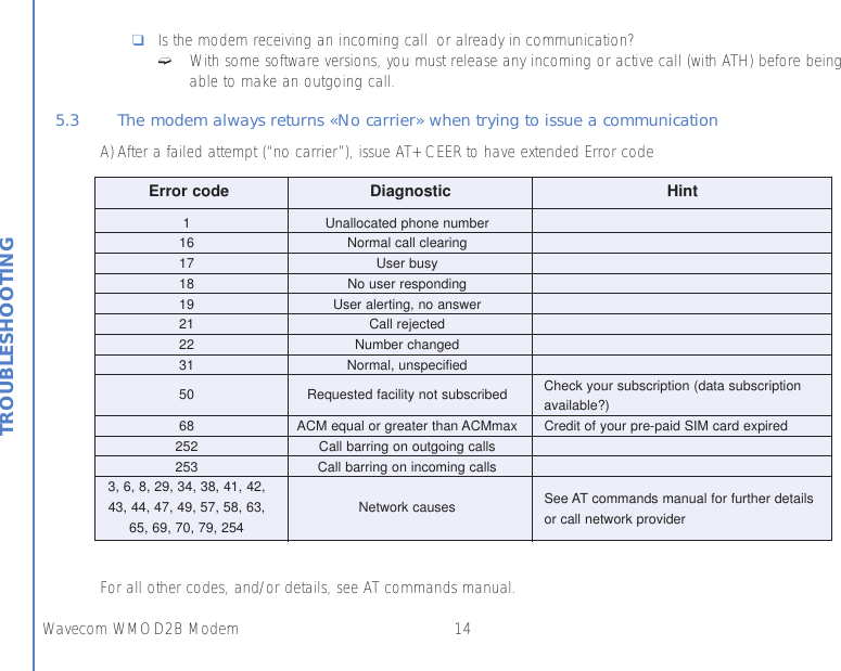
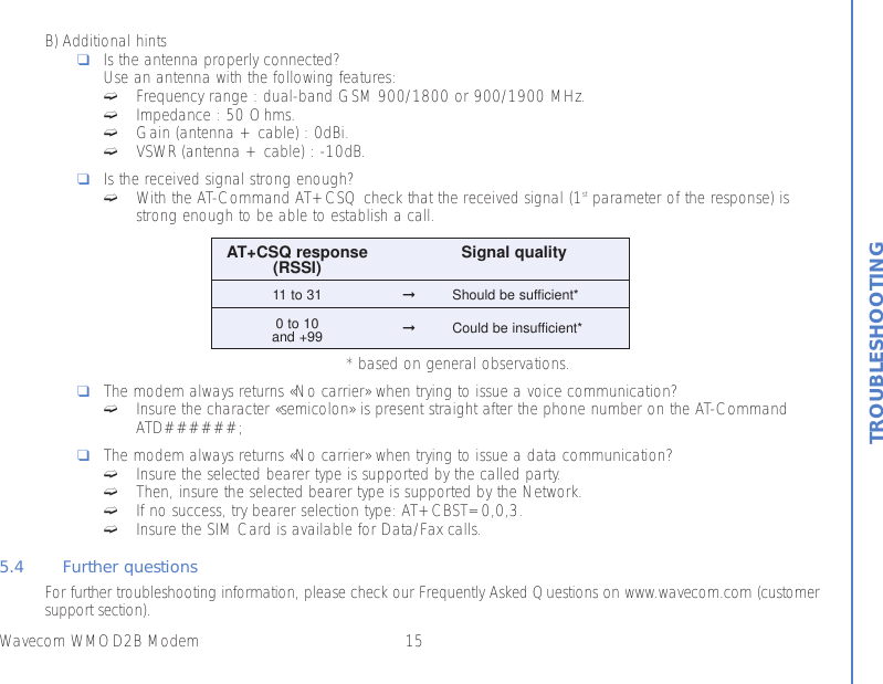
Sierra Wireless WMOD2B-G0919 Transmitter module for mobile applications User Manual

Sierra Wireless, Inc. Transmitter module for mobile applications

User Manual

WMOD2B dual-band900/1800 or 900/1900 MHz modemUSER MANUAL
Wavecom WMOD2B ModemSUMMARY1. PRODUCT DESCRIPTION 11.1 Package content 11.2 Product presentation 11.3 Physical characteristics 21.4 Functions - GSM Modes 21.5 Temperature range 22. INSTALLATION/START-UP 32.1 Mounting the modem 32.2 Installing the modem 32.3 Electrical characteristics 42.3.1 Switching the GSM modem on/off 42.3.2 Voltage range 42.3.3 Overvoltage/undervoltage 42.3.4 Power supply cable 52.3.5 Input/output electrical characteristics defined for all external connections 62.3.6 Protection/on-board network connection 63. DESCRIPTION OF THE INTERFACES 73.1 LED Function 73.2 Connectors 74. TECHNICAL DATA 11SUMMARY
Wavecom WMOD2B Modem5. TROUBLESHOOTING : Specific defaults possibly encountered 125.1 The modem does not answer through the serial link 125.2 The modem always returns «Error» when trying to issue a communication 135.3 The modem always returns «No carrier» when trying to issue a communication 141.4 Functions - GSM Modes 21.5 Temperature range 26. REFERENCE ACCESSORIES 167.1 General safety 167.2 Vehicle safety 177.3 Car And Maintenance 177.4 Your responsibility 188. GENERAL INFORMATIONS 19SUMMARY
1Wavecom WMOD2B Modem1. PRODUCT DESCRIPTIONThe Wavecom WMOD2B modem exists under two dual-band versions:- EGSM 900/1800 MHz- EGSM 900/1900 MHz1.1 Package contentThe Wavecom WMOD2B modem package comprises:- 1 Modem- 2 holding bridles- 1 Power supply cable + fuse- 1 User manual (this document)1.2 Product presentation The Wavecom WMOD2B modem supports DATA and FAX transmission, Short Messages (Point to Point and CellBroadcast) and VOICE calls.The connectors binded to the body guarantee output and input connections.An extractible holder is used to insert the SIM card (Micro-SIM type). A LED indicates the operating mode. PRODUCT DESCRIPTIONMicro-FitTMconnectorSUB HDconnectorFront capLEDExtractibleSIM holderSMAconnectorBack capFigure 1Modem presentation
2Wavecom WMOD2B Modem1.3 Physical characteristics1.4 Functions - GSM Modes1.5 Temperature rangeOperating conditions : From -20°C to +55°CStorage conditions : From -25°C to +70°CPRODUCT DESCRIPTIONDimensions 98x54x25 mm (excluding connectors)Overall dimensions 110x54x25 mmWeight < 130 gramsVolume 13.23 cm3Housing Aluminium profiledStandard Dual Band Extended GSM 900 MHz Class 4 (2W) and GSM 1800/1900 MHzClass 1 (1W)Interface Serial interface RS232 V.24/V.28 Autobauding functionAT command set based on V.25ter and GSM 07.05 & 07.07Mobile Originated (MO) and Mobile Terminated (MT).SMS Mode Text & PDU point to point. Cell broadcast.In accordance with GSM 07.05.Asynchronous 2400, 4800, 9600 and 14400 bits/s.Data Transparent and Non Transparent mode.In Non Transparent Mode only: 300, 1200, 1200/75 bauds.Mode 3.1 KHz (PSTN) and V110 (ISDN).2400/4800/7200/9600 bits/sFax GSM teleservice 62 in Transparent Mode.Class 2. Groupe 3 compatible.Audio Half Rate / Full Rate / Enhanced Full Rate. Accessories (options): handset and car-kit.
3Wavecom WMOD2B ModemINSTALLATION/START-UP2 INSTALLATION/START-UP2.1 Mounting the modemFor mounting the modem, bind to the body the holding bridles according to the schema below:2.2 Installing the modemTo install the modem, plug the device on a DC power supply (for automotive applications, connect the device onthe permanent « + » and insert the SIM card in the holder).Make sure that an antenna is connected.In order to extract or to insert the Micro SIM card, it is necessary to press the SIM holder ejectorwith a sharp element (a pen for example).If this sequence is not respected, the SIM holder could be damaged.2 mmHolding bridlesFigure 2Modem mountingNote:- To be attached to a plain surface- Screw head max. height: 2mm
4Wavecom WMOD2B ModemINSTALLATION/START-UP2.3 Electrical characteristics2.3.1 Switching the GSM modem on/offThe device is permanently powered (when connected to the power supply).2.3.2 Voltage rangeVoltage range : 5 to 32V DC GND : 0V2.3.3 Overvoltage/undervoltageCorrect operation of the Wavecom WMOD2B modem in communication mode is not guaranteed if input voltagefall below 5V. The modem is protected against voltage over 32V.When input voltages exceed 32V, the supply voltage is disconnected in order to protect the electronic componentsfrom an overvoltage.TWO CASES ARE POSSIBLE:- IF THE OVERVOLTAGE IS CONTINUOUS, THE PROTECTION IS GUARANTEED BY THE FUSE.- IN THE CASE OF TRANSIENT PEAKS, THE MODEM GUARANTEES  ITS OWN PROTECTION.
5Wavecom WMOD2B ModemINSTALLATION/START-UP2.3.4 Power supply cableA cable, included in the package shall be used for power supply connection.The wires are marked as follows:Cable : 1 wireAme : tinned copper 24x0.2 mmSection : 0.75 mm2Figure 3Power supply cable+-Side viewConnector Molex Micro-Fit 3.0TMCables stripped over 200 mm,protected by their own sheathStandard cable sheathStripped wire, tinned over 5 mm
6Wavecom WMOD2B ModemINSTALLATION/START-UP2.3.5 Input/output electrical characteristics defined for all external connections2.3.6 Protection/on-board network connection The modem is protected by a fuse directly binded on the power supply cable.Parameters GSM 900MIN TYP MAX MIN TYP MAXGSM 1800/1900 UNITPower supply @25° C:Input supply voltage 5 13.2 32 5 13.2 32 V@5V 1.8 1.1 A@13.2V 0.7 0.4 A@32V 0.4 0.2 A@5V 330 220 mA@13.2V 130 95 mA@32V 65 50 mA@5V 31.4 31.4 mA@13.2V 13.2 13.2 mA@32V 5.6 5.6 mA@5V 8.8 8.8 mA@13.2V 4.1 4.1 mA@32V 2.2 2.2 mASerial link : - RS232Audio (head set):Microphone input voltage @ lowest gain. 43.8 43.82 mVrmsSpeaker output voltage @ maximum gain. 1.65 1.65 VrmsSpeaker impedance 32 32 ΩSIM 3 or 5 3 or 5 VInput peak supply current(in communication @ Pmax)Input average supply current(in communication @ Pmax)Input average supply current in idle modeInput average supply current in idle mode(with auto-shutdown of the RS232 driver)** RS232 driver (MAX3238) automatically shutdown after 30s of inactivity on the serial link.The tests are carried out with a 3V SIM card.The power consumption might vary of 5% over the whole operating temperature range (-20°C to +55°C)
7Wavecom WMOD2B ModemDESCRIPTION OF THE INTERFACES3. DESCRIPTION OF THE INTERFACESThe modem comprises several interfaces:- LED function indicating operating status- External antenna (via SMA)- Serial and control link (via 15 pins SUB D) - Power supply (via 4 pins Micro-FitTM)-SIM card holder3.1 LED Function-LED off  Device switched off - Not ready- LED on Device switched on - Connecting to network- LED flashing slowly Device switched on - Idle mode (registered on network)- LED flashing rapidly Device switched on - Transmission mode3.2 ConnectorsConnector FunctionSMA RF antenna connector15 pins SUB D RS232 link(high density) AUDIO linkRESET4 pins Micro-FitTM Power supply connector“ SIM” connector SIM card connection
8Wavecom WMOD2B ModemDESCRIPTION OF THE INTERFACESA SIM card is needed to operate on a GSM network.To install the card:- Press the yellow button to eject the holder.- Insert the SIM card.- Check that it fits into place correctly.ExtractibleSIM card holderSIM cardYellow button toeject the holder(with a sharp element)SMA connector(antenna connector)Figure 4SMA connectorFigure 5SIM card holder
9Wavecom WMOD2B ModemDESCRIPTION OF THE INTERFACESFigure 615 pins SUB D connector(high density)Pins assignment for15 pins SUB D ConnectorPIN EIA CCIT Designation1 DCD 109 Data Carrier Detect6 RX 104 Receive Data (out)2 TX 103 Transmit Data8 DTR 108.2 Data Terminal Ready9 GND Signal ground7 DSR 107 Data Set Ready12 RTS 105 Request to send11 CTS 106 Clear to send13 RI 125 Ring indicator4 MICROPHONE (+)5 MICROPHONE (-)10 SPEAKER (+)15 SPEAKER (-)14 RESET3 RESERVEDRS232ResetAudio
10Wavecom WMOD2B ModemDESCRIPTION OF THE INTERFACES21432143Figure 74 pins Micro-FitTM connectorConnector Pins layout Comments1 V+BATTERY Power4 pins 2 GROUND supplyMicro-Fit 3.0TM 3-4 AUXI NCThe 4 pins Micro-Fit 3.0TM can be ordered from a supplier called MOLEX.
4. TECHNICAL DATADescription AT commands Module CommentsAT+CREG ? CREG=<mode>, 1 Modem synchronised on the networkCREG=<mode>, 2 Synchronisation lost, re-synchronisation attemptCREG=<mode>, 0 Modem not synchronised on the network, no synchronisation attemptRINGATA Answer the callOKATD1234; Don’t forget the « ; » at the end for « voice » callOK Communication establishedCME ERROR : 11 PIN code not entered (with + CMEE = 1 mode)CME ERROR : 3 AOC credit exceeded or a communication is already establishedATD112; Don’t forget the « ; » at the end for « voice » callOKNO CARRIERATHOKAT+CPIN=1234OK PIN Code accepted+CME ERROR : 16 Incorrect PIN Code (with +CMEE = 1 mode)+CME ERROR : 3 PIN already entered (with +CMEE = 1 mode)AT&WOK The configuration settings are stored in E2P11Wavecom WMOD2B ModemTECHNICAL DATAModule synchrocheckingReceiving anincoming callInitiate a callInitiate anemergency callCommunication lossHang upEnter PIN CodeStore theparameters in E2P
12Wavecom WMOD2B ModemTROUBLESHOOTING5. TROUBLESHOOTING: Specific defaults possibly encountered5.1 The modem does not answer through the serial linkA) Is the modem correctly powered on?❑If not, the correct power supply is 5 to 32V.B) Is the serial cable suitable and adjusted in the modem and PC sockets?❑A suitable cable must follow pin assignment described on figure 6.❑Check in particular, that Rx et Tx are properly connected.C)Check that your communication program is properly configured:❑Modem factory setting for the character framing are:➫Data Bits : 8➫Parity : None➫Stop Bits : 1❑The factory setting for the baud rate is 9600 bps.D)Does any other program interfere with your communication program (conflict on communication port access)?❑If yes, close any application likely to interfere (e.g. mouse or printer driver).
13Wavecom WMOD2B ModemTROUBLESHOOTING5.2 The modem always returns «Error» when trying to issue a communicationA) Issue AT+CMEE=1 to have extended error code and retryDiagnostic Hint0 Phone failure Call your technical support3 Operation not allowed4 Operation not supported10 SIM not inserted ➞Insert the SIM card in the SIM holder of the modem,➞If SIM card is inserted, insure that it is clean and properly inserted.11 SIM PIN required Enter PIN code12 SIM PUK required Enter PUK code (call your network provider if you don’t know this code)13 SIM Failure Check validity of your SIM card. If SIM damaged, call your network provider16 Incorrect password Check the code you entered17 SIM PIN2 required Enter PIN2 code18 SIM PUK2 required Enter PUK2 code (call your network provider if you don’t know this code)26 Dial string too long Check your phone number (max 20 digits)30 No network serviceFor all other codes, and/or details, see AT commands manual.B) Additional hints❑Is the modem registered on the network?Does the AT-Command AT + CREG? answers 0,1 (registered) or 0,5 (registered roaming)?➫If not, check that the received signal is strong enough to synchronize on the Network (use AT+CSQ).Errorcode
14Wavecom WMOD2B ModemTROUBLESHOOTING❑Is the modem receiving an incoming call or already in communication?➫With some software versions, you must release any incoming or active call (with ATH) before beingable to make an outgoing call.5.3 The modem always returns «No carrier» when trying to issue a communicationA) After a failed attempt (“no carrier”), issue AT+CEER to have extended Error code For all other codes, and/or details, see AT commands manual.Error code Diagnostic Hint1 Unallocated phone number16 Normal call clearing17 User busy18 No user responding19 User alerting, no answer21 Call rejected22 Number changed31 Normal, unspecified50 Requested facility not subscribed Check your subscription (data subscriptionavailable?)68 ACM equal or greater than ACMmax Credit of your pre-paid SIM card expired252 Call barring on outgoing calls253 Call barring on incoming calls3, 6, 8, 29, 34, 38, 41, 42,43, 44, 47, 49, 57, 58, 63, Network causes See AT commands manual for further details65, 69, 70, 79, 254 or call network provider
15Wavecom WMOD2B ModemTROUBLESHOOTINGB) Additional hints❑Is the antenna properly connected?Use an antenna with the following features:➫Frequency range : dual-band GSM 900/1800 or 900/1900 MHz.➫Impedance : 50 Ohms.➫Gain (antenna + cable) : 0dBi.➫VSWR (antenna + cable) : -10dB.❑Is the received signal strong enough?➫With the AT-Command AT+CSQ check that the received signal (1st parameter of the response) isstrong enough to be able to establish a call.* based on general observations.❑The modem always returns «No carrier» when trying to issue a voice communication?➫Insure the character «semicolon» is present straight after the phone number on the AT-CommandATD######;❑The modem always returns «No carrier» when trying to issue a data communication?➫Insure the selected bearer type is supported by the called party.➫Then, insure the selected bearer type is supported by the Network.➫If no success, try bearer selection type: AT+CBST=0,0,3.➫Insure the SIM Card is available for Data/Fax calls.5.4 Further questionsFor further troubleshooting information, please check our Frequently Asked Questions on www.wavecom.com (customersupport section).AT+CSQ response Signal quality(RSSI)11 to 31 ➞Should be sufficient*0 to 10and +99 ➞Could be insufficient*
16Wavecom WMOD2B ModemREFERENCE ACCESSORIES - NOTES ON SAFETY6. REFERENCE ACCESSORIESThe following accessories have been qualified for the WMOD2B modem:❑Dual-band antenna : ALLGON 1140.26❑Antenna adaptor : SMA/FME adaptor from PROCOM❑Power adaptor (Europe): EGSTON N2 EFSW 12V 1A mounted with micro-fit connector from MOLEX.7. NOTES ON SAFETY 7.1 General SafetyIt is important to follow any special regulations regarding the use of radio equipment due in particular to the possibi-lity of radio frequency, RF, interference. Please follow the safety advice given below carefully.❑Switch OFF your GSM Modem when in an aircraft. The use of cellular telephones in an aircraft may endan-ger the operation of the aircraft, disrupt the cellular network and is illegal. Failure to observe this instructionmay lead to suspension or denial of cellular telephone services to the offender, or legal action or both. ❑Switch OFF your GSM Modem when at a refueling point.❑Switch OFF your GSM Modem in hospitals and any other place where medical equipment may be in use.The modem is designed for and intended to be used in fixed and mobile applications. “Fixed” means that the devi-ce is physically secured at one location and is not able to be easily moved to another location. “Mobile” meansthat the device is designed to be used in other than fixed locations and generally in such a way that a separationdistance of at least 20 cm (8 inches) is normally maintained between the transmitter’s antenna and the body of theuser or nearby persons. The Modem is not designed for a intended to be used in portable applications (within 20cm of the body of the user) and such uses are strictly prohibited.
17Wavecom WMOD2B ModemNOTES ON SAFETY❑Respect restrictions on the use of radio equipment in fuel depots, chemical plants or where blasting opera-tions are in progress.❑There may be a hazard associated with the operation of your GSM Modem close to in adequately protectedpersonal medical devices such as hearing aids and pacemakers. Consult the manufactures of the medicaldevice to determine if it is adequately protected.❑Operation of your GSM Modem close to other electronic equipment may also cause interference if the equip-ment is inadequately protected. Observe any warning signs and manufacturers recommendations.7.2 Vehicle Safety❑Do not use your GSM Modem while driving, unless equipped with a correctly installed vehicle kit allowing‘Hands-Free’ Operation.❑Respect national regulations on the use of cellular telephones in vehicles. Road safety always comes first.❑If incorrectly installed in a vehicle, the operation of GSM Modem telephone could interfere with the correctfunctioning of vehicle electronics. To avoid such problems, ensure that the installation has been performedby a qualified personnel. Verification of the protection of vehicle electronics should form part of the installa-tion.❑The use of an alert device to operate a vehicle’s lights or horn on public roads is not permitted.7.3 Car And MaintenanceYour GSM Modem is the product of advanced engineering, design and craftsmanship and should be treated with care.The suggestion below will help you to enjoy this product for many years.
18Wavecom WMOD2B ModemNOTES ON SAFETY❑Do not expose the GSM Modem to any extreme environment where the temperature or humidity is high.❑Do not attempt to disassemble the GSM Modem. There are no user serviceable parts inside.❑Do not expose the GSM Modem to water, rain or spilt beverages, It is not waterproof.❑Do not abuse your GSM Modem by dropping, knocking, or violent shaking. Rough handling can damage it.❑Do not place the GSM Modem alongside computer discs, credit or travel cards or other magnetic media. Theinformation contained on discs or cards may be affected by the phone.❑The use of third party equipment or accessories, not  made or authorized by Wavecom may invalidate thewarranty of GSM Modem.❑Do contact an authorized Service Center in the unlikely event of a fault.7.4 Your ResponsibilityThis GSM Modem is under your responsibility. Please treat it with care respecting all local regulations. It is not a toytherefore keep it in a safe place at all times and out of the reach of children.Try to remember your Unlock and PIN codes. Become familiar with and use the security features to block unauthori-zed use and theft.
19Wavecom WMOD2B ModemGENERAL INFORMATIONS8. GENERAL INFORMATIONSGSM reference documents : GSM 03.40, GSM 03.45, GSM 04.11,GSM 04.21, GSM 05.08, GSM 07.01,GSM 07.02, GSM 07.05, GSM 07.07.ETSI contact : ETSI SecretariatF-06921 Sophia Antipolis Cedex, Francee-mail : secretariat@etsi.frService : The AT commands manual is available from your local modem supplier.DisclaimerModem and GSM-unit specifications and manuals are subject to change without notice. Wavecom assumes no liabi-lity for damage incurred directly or indirectly from errors, omissions or discrepancies between the modem or GSM-unitand their manuals.TrademarksSome mentioned products are registred trademarks of them respective companies.CopyrightThis manual is copyrighted by Wavecom with all rights reserved. No part of this manual may be reproduced in anyform without the prior written permission of Wavecom.No patent liability is assumed with respect to the use of the information contained herein.
www.wavecom.comWAVECOM Headquaters - 39, rue du Gouverneur Général Eboué, 92442 Issy-les-Moulineaux cedex - FranceTel: +33 1 46 29 08 00 - Fax: +33 1 46 29 08 08WAVECOM Inc. - 610 West Ash Street, Suite 1400 - San Diego, CA 92101 - USATel: +1 619 235 9702 - Fax: +1 619 235 9844WAVECOM Asia Pacific Limited - 5/F, Shui On Centre, 6/8 Harbour Road - Hong Kong PRCTel: +852 2824 0254 - Fax: +852 2824 0255WAVECOM Asia Pacific Limited - Tokyo Branch - 4/F, East Tower, Otemachi First Square, 1-5-1 Otemachi, Chiyoda-KuTokyo 100-0004 - Japan - Tel: +81 (0)3 5219 1350 - Fax: +81 (0)3 5219 1450WAVECOM, WISMO and WISMO Within are trademarks filed by WAVECOM S.A.,is a copyrighted material © copyright WAVECOM S.A. 4/01
NOTICE TO OEM’SNOTICE:  THE FOLLOWING STATEMENT MUST BE INCLUDED IN MANUAL FURNISHED TOTHE END USER.A minimum separation distance distance of 20 cm must be maintained between the antenna andpersons for this device to satisfy the RF Exposure requirements of the FCC.  For fixed mountoperation, the antenna co-location requirements of Section 1.1307(b)(3) of the FCC rules must besatisfied. For fixed mount operation, the maximum gain of the antenna must not exceed 7 dBi.  Formobile operation, the maximum gain of the antenna must not exceed 3 dBi.WARNING! Use of this module in portable operations is not permitted.

Navigation menu