Sierra Wireless WMOI3A Transmitter module for mobile applications User Manual
Sierra Wireless, Inc. Transmitter module for mobile applications Users Manual
Contents
- 1. Users Manual
- 2. Users Manual with Addendum
Users Manual

WMOi3 Integrated Modem
Main Electrical Parameter
and Functional
Specification
1
Users Manual

WMOi3 integrated Modem
confidential
©
This document is the sole and exclusive property of WAVECOM. Not to be distributed or divulged
without prior written agreement. Ce document est la propriété exlcusive de WAVECOM. Il ne peut
être communiqué ou divulgué à des tiers sans son autorisation préalable.
2
Contents / Sommaire
1 Introduction ................................................................................... 3
1.1 Scope ..................................................................................................... 3
2 Generality....................................................................................... 3
2.1 Overview ................................................................................................ 3
2.2 Physical characteristics........................................................................... 3
2.3 Integrated Modem Design ...................................................................... 4
3 Interface Description ..................................................................... 5
3.1 The main connector................................................................................ 5
3.2 PIN Description....................................................................................... 8
3.2.1 Power Supply ......................................................................................... 8
3.2.2 Serial Link RS232......................................................................................... 8
3.2.3 Remote SIM Interface ............................................................................. 9
3.2.4 Audio...................................................................................................... 9
3.3 SIM Interface........................................................................................ 11
3.4 RF Interface .......................................................................................... 11
4 Connectors................................................................................... 12
4.1 Interface Connector .............................................................................. 12
4.2 RF Connector........................................................................................ 12
5 Safety Precautions .......................................................................13
5.1 Safety in explosive substance environments......................................... 13
5.2 Aircraft safety....................................................................................... 13
5.3 Safety in medical equipment environments .......................................... 13
5.4 Vehicle safety ....................................................................................... 13
5.5 Precautions in case of loss or theft ....................................................... 14
5.6 Precautions for antenna release............................................................ 14
5.7 Conclusion............................................................................................ 14

WMOi3 integrated Modem
confidential
©
This document is the sole and exclusive property of WAVECOM. Not to be distributed or divulged
without prior written agreement. Ce document est la propriété exlcusive de WAVECOM. Il ne peut
être communiqué ou divulgué à des tiers sans son autorisation préalable.
3
1 Introduction
1.1
1.11.1
1.1 Scope
ScopeScope
Scope
This document describes the interfaces, the technical specifications, the main
electrical parameters and functional descriptions for the integrated modem
called WMOi3. This product includes a WM2C-G900-G1900 EGSM/PCS dual
band module (pls refer to the WM2C-G900/G1900 specifications).
2 Generality
2.1
2.12.1
2.1 Overview
OverviewOverview
Overview
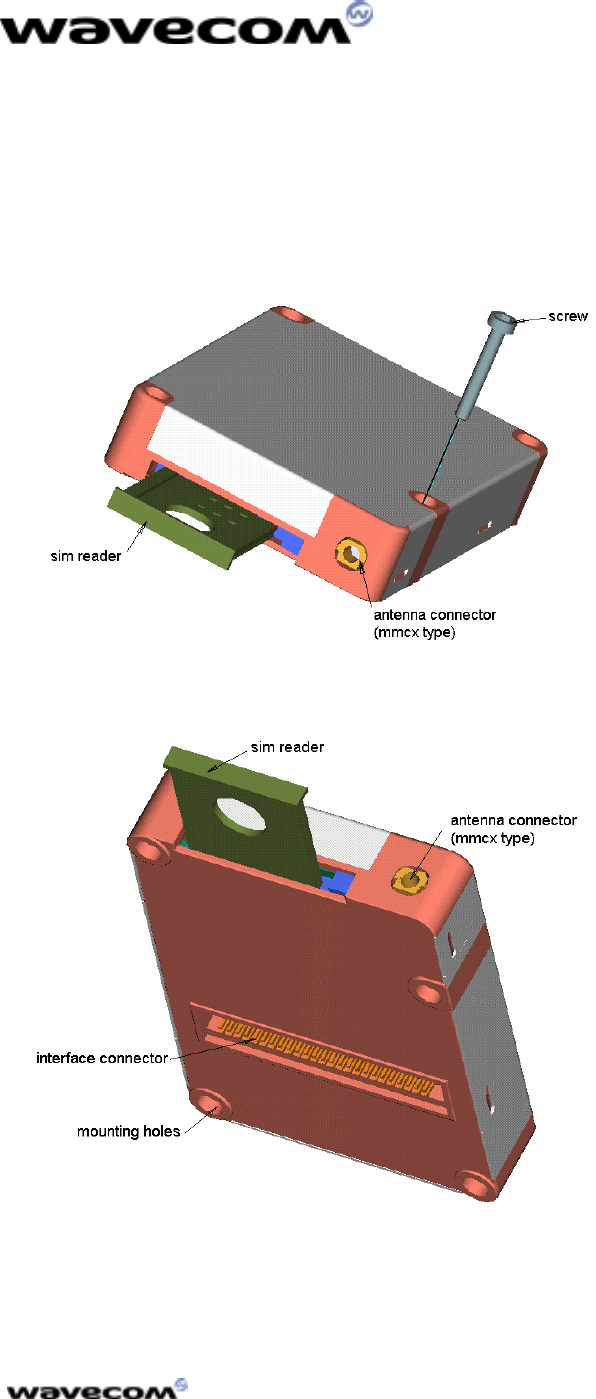
The integrated modem is a product with a sole connector which puts together
all the interface signals in order to facilitate its integration.
It has an integrated SIM connector as well as a standard RF connector type
MMCX (Miniature Micro Connector).
2.2
2.22.2
2.2 Physical characteristics
Physical characteristicsPhysical characteristics
Physical characteristics
The WMOI3 integrated modem has a complete self-contained shield.
The physical characteristics are the following ones:
Physical characteristic Qualification
Dimension
Absolute maximum
dimension
46 x64 x 12.4
mm
Weight About 80 g
Volume 36.21 cm3
Case Zamack +
stainless steel
WMOi3 integrated Modem
confidential
©
This document is the sole and exclusive property of WAVECOM. Not to be distributed or divulged
without prior written agreement. Ce document est la propriété exlcusive de WAVECOM. Il ne peut
être communiqué ou divulgué à des tiers sans son autorisation préalable.
4
2.3
2.32.3
2.3 Integrated Modem Design
Integrated Modem DesignIntegrated Modem Design
Integrated Modem Design
WMOi3 integrated Modem
confidential
©
This document is the sole and exclusive property of WAVECOM. Not to be distributed or divulged
without prior written agreement. Ce document est la propriété exlcusive de WAVECOM. Il ne peut
être communiqué ou divulgué à des tiers sans son autorisation préalable.
5
3 Interface Description
3.1
3.13.1
3.1 The main connector
The main connectorThe main connector
The main connector
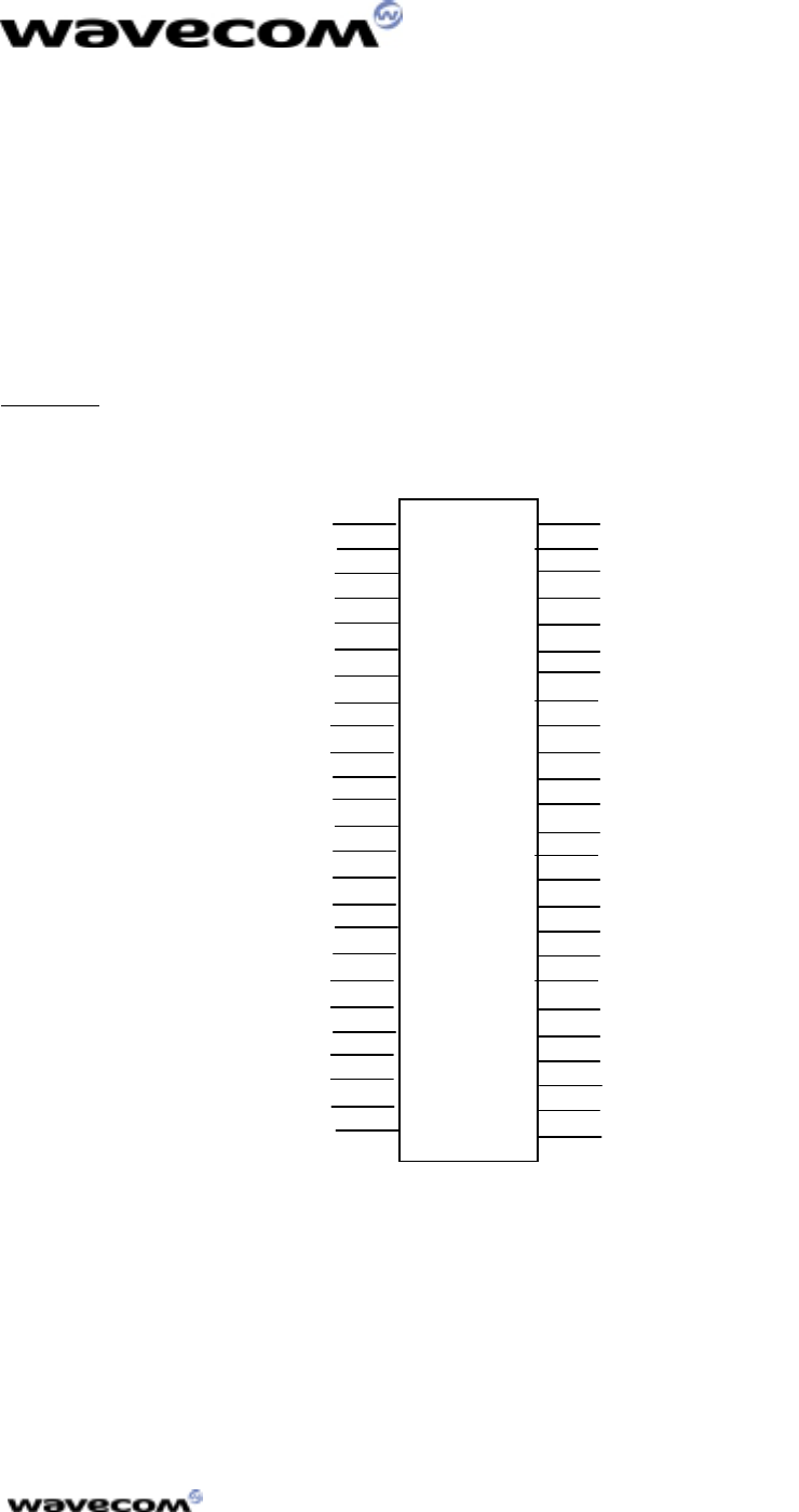
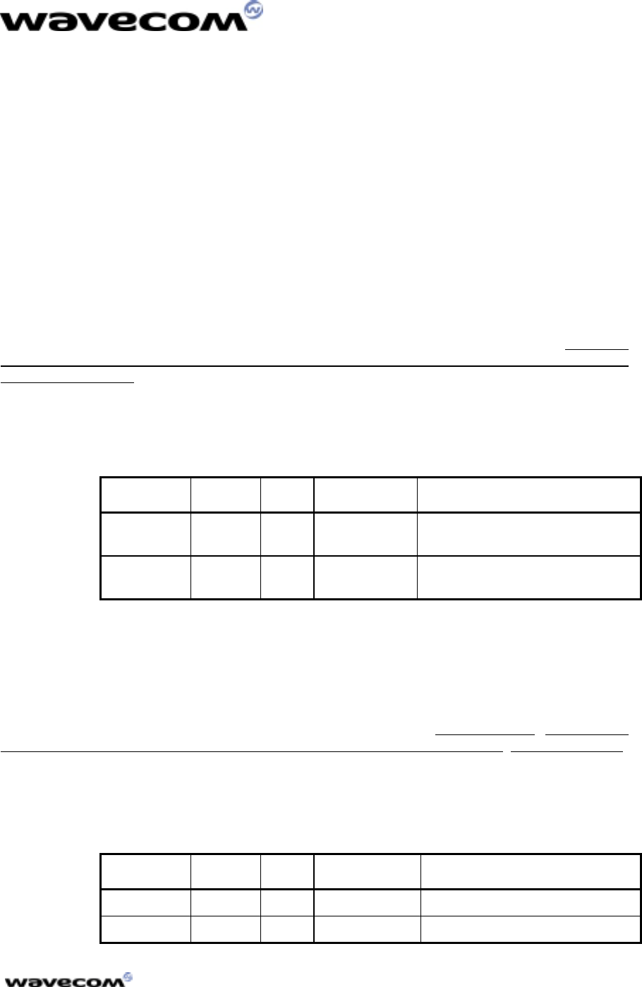
This is a 50 pins interface connector with a pitch of 1.27 from SAMTEC,
referenced FTS-125-01-L-DV.
FTS-125-01-L-DV. FTS-125-01-L-DV.
FTS-125-01-L-DV. (see figure1)
Figure 1
Figure 1Figure 1
Figure 1 : 50 pins connector Bottom view
: 50 pins connector Bottom view : 50 pins connector Bottom view
: 50 pins connector Bottom view
GND
+5V
GND
SPK2N
SPK2P
SPK1P
SPK1N
MIC2P
MIC2N
MIC1P
MIC1N
GND
GPIO0
CT104/RX
CT105/RTS
COL4
COL2
COL0
ROW3
ROW1
SPI_EN
SPI_CLK
SIMRST
SIMPRES1
GND
GND
+5V
CT109/DCD
GPIO2
CT125/RI
GPIO1
CT106/CTS
ON/~OFF
AUXV0
~RST
GND
BOOT
CT103/TX
CT107/DSR
CT108-2/DTR
COL3
COL1
ROW4
ROW2
ROW0
GND
SPI_IO
SIMCLK
SIMVCC
SIMDATA
1
3
5
7
9
11
13
15
17
19
21
23
25
27
29
31
33
35
37
39
41
43
45
47
49
2
4
6
8
10
12
14
16
18
20
22
24
26
28
30
32
34
36
38
40
42
44
46
48
50

WMOi3 integrated Modem
confidential
©
This document is the sole and exclusive property of WAVECOM. Not to be distributed or divulged
without prior written agreement. Ce document est la propriété exlcusive de WAVECOM. Il ne peut
être communiqué ou divulgué à des tiers sans son autorisation préalable.
6
The following table describes the electrical characteristics of the interface.
Some signals require particular connections and are specified in bold
characters.
Pin #
Pin #Pin #
Pin # Name
NameName
Name I/O
I/OI/O
I/O I/O type
I/O typeI/O type
I/O type Description
DescriptionDescription
Description Comment
CommentComment
Comment
1 GND GROUND High current
2 GND GROUND High current
3 +5V I Supply High current
4 +5V I Supply High current
5 CT109/DCD O CMOS/2X RS232-Data Carrier
Detect
6 GND GROUND High current
7 GPIO2 I/O CMOS/2X General Purpose I/O
8 SPK2N O Analog Speaker2 negative
output
9 CT125/RI O CMOS/2X RS232-Ring Indicator
10 SPK2P O Analog Speaker 2 positive
output
11 GPIO1 I/O CMOS/2X General Purpose I/O
12 SPK1P O Analog Speaker 1 positive
output
13 CT106/CTS O 1X RS232 interface Clear
To Send
14 SPK1N O Analog Speaker 1 negative
output
15 ON/~OFF I Power ON/OFF control
16 MIC2P I Analog Microphone 2 positive
input
17 AUXV0 I Analog Auxiliary ADC input
18 MIC2N I Analog Microphone 2 negative
input
19 ~RST
~RST~RST
~RST I Reset active low Open Collector
Open CollectorOpen Collector
Open Collector
20 MIC1P I Analog Microphone 1 positive
input
21 GND
GNDGND
GND I Ground
22 MIC1N I Analog Microphone 1 negative
input
23 BOOT
BOOTBOOT
BOOT I BOOT Open Collector
Open CollectorOpen Collector
Open Collector
24 GND GROUND High current
25 CT103/TX
CT103/TXCT103/TX
CT103/TX I RS232 interface -
Transmit Pull up to VCC
Pull up to VCCPull up to VCC
Pull up to VCC
with 100K
with 100Kwith 100K
with 100KΩ
ΩΩ
Ω
when not used
when not usedwhen not used
when not used
26 GPIO0 I/O CMOS/2X General Purpose I/O
27 CT107/DSR O 1X RS232 interface
Data Set Ready
28 CT104/RX O 1X RS232 interface –
Receive

WMOi3 integrated Modem
confidential
©
This document is the sole and exclusive property of WAVECOM. Not to be distributed or divulged
without prior written agreement. Ce document est la propriété exlcusive de WAVECOM. Il ne peut
être communiqué ou divulgué à des tiers sans son autorisation préalable.
7
29 CT108-
CT108-CT108-
CT108-
2/DTR
2/DTR2/DTR
2/DTR I RS232 interface
Data Terminal Ready Pull up to VCC
Pull up to VCCPull up to VCC
Pull up to VCC
with 100K
with 100Kwith 100K
with 100KΩ
ΩΩ
Ω
when not used
when not usedwhen not used
when not used
30 CT105/RTS
CT105/RTSCT105/RTS
CT105/RTS I RS232 interface
Request To Send Pull up to VCC
Pull up to VCCPull up to VCC
Pull up to VCC
with 100K
with 100Kwith 100K
with 100KΩ
ΩΩ
Ω
when not used
when not usedwhen not used
when not used
31 COL3 I/O 1X Keyboard column
32 COL4 I/O 1X Keyboard column
33 COL1 I/O 1X Keyboard column
34 COL2 I/O 1X Keyboard column
35 ROW4 I/O 1X Keyboard row
36 COL0 I/O 1X Keyboard column
37 ROW2 I/O 1X Keyboard row
38 ROW3 I/O 1X Keyboard row
39 ROW0 I/O 1X Keyboard row
40 ROW1 I/O 1X Keyboard row
41 GND GROUND High current
42 SPI_EN O 1X SPI enable
43 SPI_IO I/O 1X I2C Data or SPI Data
44 SPI_CLK O 1X I2C Clock or SPI Clock
45 SIMCLK
SIMCLKSIMCLK
SIMCLK O 2X Clock for SIM Interface 3V mode
3V mode3V mode
3V mode
46 SIMRST
SIMRSTSIMRST
SIMRST O 2X Reset for SIM interface 3V mode
3V mode3V mode
3V mode
47 SIMVCC
SIMVCCSIMVCC
SIMVCC O SIM card supply 3V mode
3V mode3V mode
3V mode
6mA
6mA 6mA
6mA max
maxmax
max
48 SIMPRES1
SIMPRES1SIMPRES1
SIMPRES1 I SIM card detect Connected to
Connected toConnected to
Connected to
SIM connector
SIM connectorSIM connector
SIM connector
pin 8.
pin 8.pin 8.
pin 8.
Pin 4 of SIM
Pin 4 of SIMPin 4 of SIM
Pin 4 of SIM
connector must
connector mustconnector must
connector must
be pulled down
be pulled downbe pulled down
be pulled down
to GND with 1
to GND with 1to GND with 1
to GND with 1
K
KK
KΩ
ΩΩ
Ω
49 SIMDATA
SIMDATASIMDATA
SIMDATA I/O 3X I/O for SIM interface 3V mode
3V mode3V mode
3V mode
50 GND GROUND High current
Nota : VCC could be either 3V or 5V.
Nota : VCC could be either 3V or 5V.Nota : VCC could be either 3V or 5V.
Nota : VCC could be either 3V or 5V.
All digital I/O are CMOS 3V compatible.
Operating conditions
Parameter I/O type Min Max Condition
VIL CMOS -0.5V 0.8V
VIH CMOS 2.1V 3.0V
1X 0.2V IOL = -1 mA
2X 0.2V IOL = -2 mA
VOL
3X 0.2V IOL = -3 mA
1X 2.6V IOH = 1 mA
VOH 2X 2.6V IOH = 2 mA
WMOi3 integrated Modem
confidential
©
This document is the sole and exclusive property of WAVECOM. Not to be distributed or divulged
without prior written agreement. Ce document est la propriété exlcusive de WAVECOM. Il ne peut
être communiqué ou divulgué à des tiers sans son autorisation préalable.
8
3X 2.6V IOH = 3 mA
3.2
3.23.2
3.2 PIN Description
PIN DescriptionPIN Description
PIN Description
3.2.1
3.2.13.2.1
3.2.1 Power Supply
Power Supply Power Supply
Power Supply
The main power supply will be provided through a double connection.
These connections are respectively the pin 3 and 4 for the +5V and the pins 1
and 2 for the ground (GND).
The power supply is 5V +/-5% 1A.
3.2.2 Serial Link RS232
This interface is needed for communication with a remote terminal with
respect to the RS232 V.28 standard levels. As the integrated modem does not
include a transceiver MAX3238 or MAX3237, this one has to be added outside
with a SUBD9. The connection between the WMOi3 and the transceiver must
not exceed 10 cm. The table below lists the needed signals for this interface :
PIN number
PIN numberPIN number
PIN number Signal
SignalSignal
Signal Description
DescriptionDescription
Description
5 DCD Data Carrier Detect
28 RX Reception
25 TX Transmission
29 DTR Data Terminal Ready
27 DSR Data Set Ready
30 RTS Request To Send
13 CTS Clear To Send
9 RING Ring indicator
2GND Ground
When the RS232 V.28 level is not needed, the above signals can be used as
TTL 3V CMOS compatible signals.
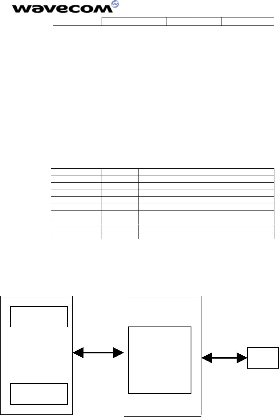
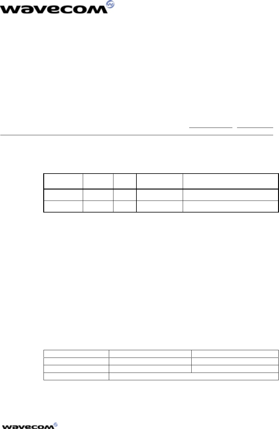
Application example needing V.28 levels :
Application example needing V.28 levels :Application example needing V.28 levels :
Application example needing V.28 levels :
Integrated
modem
50 PIN
CONNECTOR
RS 232
INTERFACE
TRANSCEIVER
+
SUBD9
PC
10 cm max.
Standard RS232
WMOi3 integrated Modem
confidential
©
This document is the sole and exclusive property of WAVECOM. Not to be distributed or divulged
without prior written agreement. Ce document est la propriété exlcusive de WAVECOM. Il ne peut
être communiqué ou divulgué à des tiers sans son autorisation préalable.
9
3.2.3
3.2.33.2.3
3.2.3 Remote SIM Interface
Remote SIM Interface Remote SIM Interface
Remote SIM Interface
A SIM connector is already integrated on the integrated modem (see 3.3 SIM
interface). However there is the possibility to implement a remote SIM
connector using the signals described in the table below.
PIN number
PIN numberPIN number
PIN number Signal
SignalSignal
Signal
47 SIMVCC
46 SIMRST
45 SIMCLK
50 GND
49 SIMDATA
48 SIMPRES
3.2.4
3.2.43.2.4
3.2.4 Audio
Audio Audio
Audio
The modem allows the connection of a handset or a headset through AUDIO
signals
The audio end stage must respects the following specifications :
3.2.4.1 Microphone 2
The MIC2 inputs are differential ones. They already include the convenient
biasing for an electret microphone (0,5 mA and 2 Volts). This electret
microphone can be directly connected on these inputs. The impedance of the
microphone 2 has to be around 2kΩ. These inputs are the standard ones for an
handset design while MIC1 inputs can be connected to an external headset or
a handsfree kit.
The gain of MIC2 inputs is internally adjusted. The gain can be tuned from
30dB to 51dB. The connexion to the microphone is direct.
Pin description
Pin descriptionPin description
Pin description
Signal
SignalSignal
Signal Pin #
Pin #Pin #
Pin # I/O
I/OI/O
I/O I/O type
I/O typeI/O type
I/O type Description
DescriptionDescription
Description
MIC2P 16 I Analog Microphone 2 positive
input
MIC2N 18 I Analog Microphone 2 negative
input
WMOi3 integrated Modem
confidential
©
This document is the sole and exclusive property of WAVECOM. Not to be distributed or divulged
without prior written agreement. Ce document est la propriété exlcusive de WAVECOM. Il ne peut
être communiqué ou divulgué à des tiers sans son autorisation préalable.
10
3.2.4.2 Microphone 1
The MIC1 inputs are differential and do not include internal bias. To use these
inputs with an electret microphone, bias has to be generated outside the
WMOI3 modem according to the characteristic of this electret microphone.
These inputs are the standard ones used for an external headset or a handsfree
kit. The connection can be either differential or single-ended but using a
differential connection in order to reject common mode noise and TDMA noise
is recommended. When using a single-ended connection, be sure to have a
very good ground plane, a very good filtering as well as shielding in order to
avoid any disturbance on the audio path.
The gain of MIC1 inputs is internally adjusted. The gain can be tuned from
30dB to 51dB. Pin description
Pin descriptionPin description
Pin description
Signal
SignalSignal
Signal Pin #
Pin #Pin #
Pin # I/O
I/OI/O
I/O I/O type
I/O typeI/O type
I/O type Description
DescriptionDescription
Description
MIC1P 20 I Analog Microphone 1 positive
input
MIC1N 22 I Analog Microphone 1 negative
input
3.2.4.3 Speaker 2
Speaker outputs SPK2 are push-pull amplifiers and can be loaded down to 50
Ohms and up to 1nF. These outputs are differential and the output power can
be adjusted by step of 2dB. The output can be directly connected to a speaker.
The connection can be differential or single-ended but using a differential
connection to reject common mode noise and TDMA noise is recommended.
When using a single-ended connection, be sure to have a very good ground
plane, a very good filtering as well as shielding in order to avoid any
disturbance on the audio path.
Pin description
Pin descriptionPin description
Pin description
Signal
SignalSignal
Signal Pin #
Pin #Pin #
Pin # I/O
I/OI/O
I/O I/O type
I/O typeI/O type
I/O type Description
DescriptionDescription
Description
SPK2P 10 O Analog Speaker 2 positive output
SPK2N 8 O Analog Speaker 2 negative output
WMOi3 integrated Modem
confidential
©
This document is the sole and exclusive property of WAVECOM. Not to be distributed or divulged
without prior written agreement. Ce document est la propriété exlcusive de WAVECOM. Il ne peut
être communiqué ou divulgué à des tiers sans son autorisation préalable.
11
3.2.4.4 Speaker 1
Speaker outputs SPK1 are push-pull amplifiers and can be loaded down to 50
Ohms and up to 1nF. These outputs are differential and the output power can
be adjusted by step of 2dB. The output can be directly connected to a speaker.
The connection can be differential or single-ended but using a differential
connection to reject common mode noise and TDMA noise is recommended.
When using a single-ended connection, be sure to have a very good ground
plane, a very good filtering as well as a shielding in order to avoid any
disturbance on the audio path.
Pin description
Pin descriptionPin description
Pin description
Signal
SignalSignal
Signal Pin #
Pin #Pin #
Pin # I/O
I/OI/O
I/O I/O type
I/O typeI/O type
I/O type Description
DescriptionDescription
Description
SPK1P 12 O Analog Speaker 1 positive output
SPK1N 14 O Analog Speaker 1 negative output
3.3
3.33.3
3.3 SIM Interface
SIM InterfaceSIM Interface
SIM Interface
The provided SIM connector has been designed for 3V technology
for 3V technology for 3V technology
for 3V technology SIMs only.
SIMs only.SIMs only.
SIMs only.
The remote Sim connector must be placed
at 10cm max. from the WMOi3.
3.4
3.43.4
3.4 RF Interface
RF InterfaceRF Interface
RF Interface
The RF connector is MMCX (Miniature Micro Connector) standard type for a
surface mounting.
An antenna can be directly connected through the matting connector or using
a small MMCX / SMA adapter.
The antenna must comply with the following specifications :
EGSM
EGSMEGSM
EGSM PCS
PCSPCS
PCS
Frequency RX
Frequency RXFrequency RX
Frequency RX 925 to 960 MHz 1930 to 1990 MHz
Frequency TX
Frequency TXFrequency TX
Frequency TX 880 to 915 MHz 1850 to 1910 MHz
Impedance
ImpedanceImpedance
Impedance 50
WMOi3 integrated Modem
confidential
©
This document is the sole and exclusive property of WAVECOM. Not to be distributed or divulged
without prior written agreement. Ce document est la propriété exlcusive de WAVECOM. Il ne peut
être communiqué ou divulgué à des tiers sans son autorisation préalable.
12
4 Connectors
4.1
4.14.1
4.1 Interface Connector
Interface ConnectorInterface Connector
Interface Connector
The main connector is a 50 pins interface connector from SAMTEC.
Reference
ReferenceReference
Reference Type
TypeType
Type Remarks
RemarksRemarks
Remarks
CLP-125-02-L-D Low Profile Standard connector used on starter kit board
FLE-125-02-S-D High
Profile To be used if you place components below the modem
FFSD-25-04.00-01-
NFlat cable TBD
4.2
4.24.2
4.2 RF Connector
RF ConnectorRF Connector
RF Connector
The standard RF connector is a MMCX type (Miniature Micro
Connector) from Amphenol, IMS, ….
Amphenol Reference Type Coax cable reference
908-41300 Straight plug RG-174, 188, 316
908-41200 Straight plug RG-178, 196
908-43300 Right Angle plug RG-174, 188, 316
908-43200 Right Angle plug RG-178, 196

WMOi3 integrated Modem
confidential
©
This document is the sole and exclusive property of WAVECOM. Not to be distributed or divulged
without prior written agreement. Ce document est la propriété exlcusive de WAVECOM. Il ne peut
être communiqué ou divulgué à des tiers sans son autorisation préalable.
13
5 Safety Precautions
It is important to follow any special regulations regarding the use of radio
equipment due in particular to the possibility of radio frequency, RF,
interference. Please follow the safety advice given below carefully.
5.1
5.15.1
5.1 Safety in explosive substance environments
Safety in explosive substance environments Safety in explosive substance environments
Safety in explosive substance environments
• WMOI3 is not recommended to be used in a gas station.
• In fuel depots, chemical plants and locations where explosives are
ignited , users are reminded to comply with restrictions regarding the
use of radio devices.
5.2
5.25.2
5.2 Aircraft safety
Aircraft safety Aircraft safety
Aircraft safety
The use of WMOI3 on board aircraft is forbidden by law. Consequently, Switch
OFF
OFF OFF
OFF your modem when in an aircraft, disrupt the cellular network is illegal.
Failure to observe this instruction may lead to suspension or denial of cellular
telephone services to the offender, or legal action or both.
5.3
5.35.3
5.3 Safety in medical equipment environments
Safety in medical equipment environmentsSafety in medical equipment environments
Safety in medical equipment environments
Switch OFF
OFFOFF
OFF your WMOI3 when in hospital. There may be a hazard associated
with the operation of your modem close to inadequately protected personal
medical devices such as hearing aids and pacemakers. Please address all
questions to the medical devices manufacturer to determine if it is adequately
protected.
5.4
5.45.4
5.4 Vehicle safety
Vehicle safety Vehicle safety
Vehicle safety
• Do not use your WMOI3 modem while driving, unless equipped with a
correctly installed vehicle hands-free kit.
• Comply with national regulations on the use of cellular telephones in
vehicles.
• If incorrectly installed in a vehicle, the WMOI3 modem could interfere
with the correct functioning of vehicle electronics. To avoid such
problems, ensure that the installation has been performed by a skilled
personnel.
• Safety on the road requires that it is not permitted to signal incoming
calls by sounding the vehicle’s horn or flashing the lights.

WMOi3 integrated Modem
confidential
©
This document is the sole and exclusive property of WAVECOM. Not to be distributed or divulged
without prior written agreement. Ce document est la propriété exlcusive de WAVECOM. Il ne peut
être communiqué ou divulgué à des tiers sans son autorisation préalable.
14
5.5
5.55.5
5.5 Precautions in case of loss or theft
Precautions in case of loss or theft Precautions in case of loss or theft
Precautions in case of loss or theft
In case of missing your WMOI3 and/or your SIM card, please notify your
network operator immediately in order to avoid misuse.
5.6
5.65.6
5.6 Precautions for antenna release
Precautions for antenna release Precautions for antenna release
Precautions for antenna release
It is important to make sure that the antenna stands in an open space for a
proper functioning of the WMOI3 wireless modem.
5.7
5.75.7
5.7 Conclusion
ConclusionConclusion
Conclusion
Your WMOi3 modem is the product of advanced engineering, design and
craftsmanship carried out by Wavecom and it should be treated with care.