Sigma Designs SG-UZB UZB Z-Wave USB Adapter User Manual 8 UZB D03
Sigma Designs Inc UZB Z-Wave USB Adapter 8 UZB D03
User Manual
UZB Z-Wave USB Adapter
1 1
All information are correct at the time of release. Sigma Designs owns the proprietary rights to the information contained herein this document. It may not be
edited, copied or circulated without prior written agreement by Sigma Designs.
© 2012 Sigma Designs, Inc.
UZB
Z-Wave USB Adapter
User’s Manual

UZB Z-Wave USB Adapter
1 1
All information are correct at the time of release. Sigma Designs owns the proprietary rights to the information contained herein this document. It may not be
edited, copied or circulated without prior written agreement by Sigma Designs.
© 2012 Sigma Designs, Inc.
CONTENTS
1.
INTRODUCTION ..........................................................................................................................3
2.
LED INDICATORS .........................................................................................................................4
3.
SPECIFICATIONS ..........................................................................................................................4
4.
PC CONTROLLER APPLICATION SOFTWER INSTALLATION .............................................................5
4.1
Installation ............................................................................................................................5
4.2
Start the Z-Wave PC Controller application .............................................................................8
4.3
Remove Z-Wave PC Controller application Software ...............................................................9
4.4
User Interface ...................................................................................................................... 10
5.
FCC NOTICE TO USERS ............................................................................................................... 22
6.
EU DECLARATION OF CONFORMITY ........................................................................................... 23
UZB Z-Wave USB Adapter
1 1
All information are correct at the time of release. Sigma Designs owns the proprietary rights to the information contained herein this document. It may not be
edited, copied or circulated without prior written agreement by Sigma Designs.
© 2012 Sigma Designs, Inc.
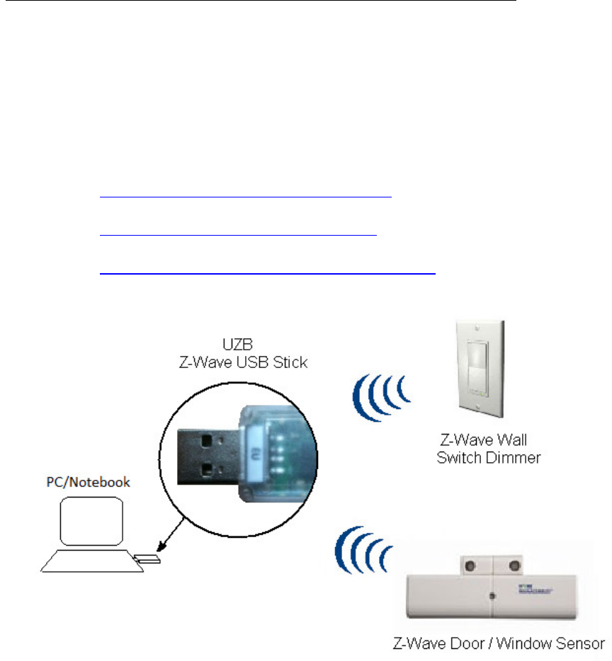
1. INTRODUCTION
UZB, Z-Wave USB Stick and bundled application software (PC Controller) enables you to control a
range of Z-Wave enabled devices through your PC or Notebook.
Z-wave is an established short range interoperable two way RF mesh network technology.
Refer to http://www.z-wave.com/modules/ZwaveStart/ for detail of the technology.
Refer to http://www.z-wave.com/modules/Products/ for various Z-Wave ready products.
Refer to http://www.z-wavealliance.org/modules/AllianceStart/ for Z-Wave Alliances.
Features
Simply plug in UZB to USB port of a PC/Notebook with PC Controller installed
Fully compatible with Z-wave enable network that can communicate with any Z-wave
certified device.
System Requirements
Windows 2000/XP/Vista 7 32 & 64 bit
Linux kernel 2.6.24+
UZB Z-Wave USB Adapter
1 1
All information are correct at the time of release. Sigma Designs owns the proprietary rights to the information contained herein this document. It may not be
edited, copied or circulated without prior written agreement by Sigma Designs.
© 2012 Sigma Designs, Inc.
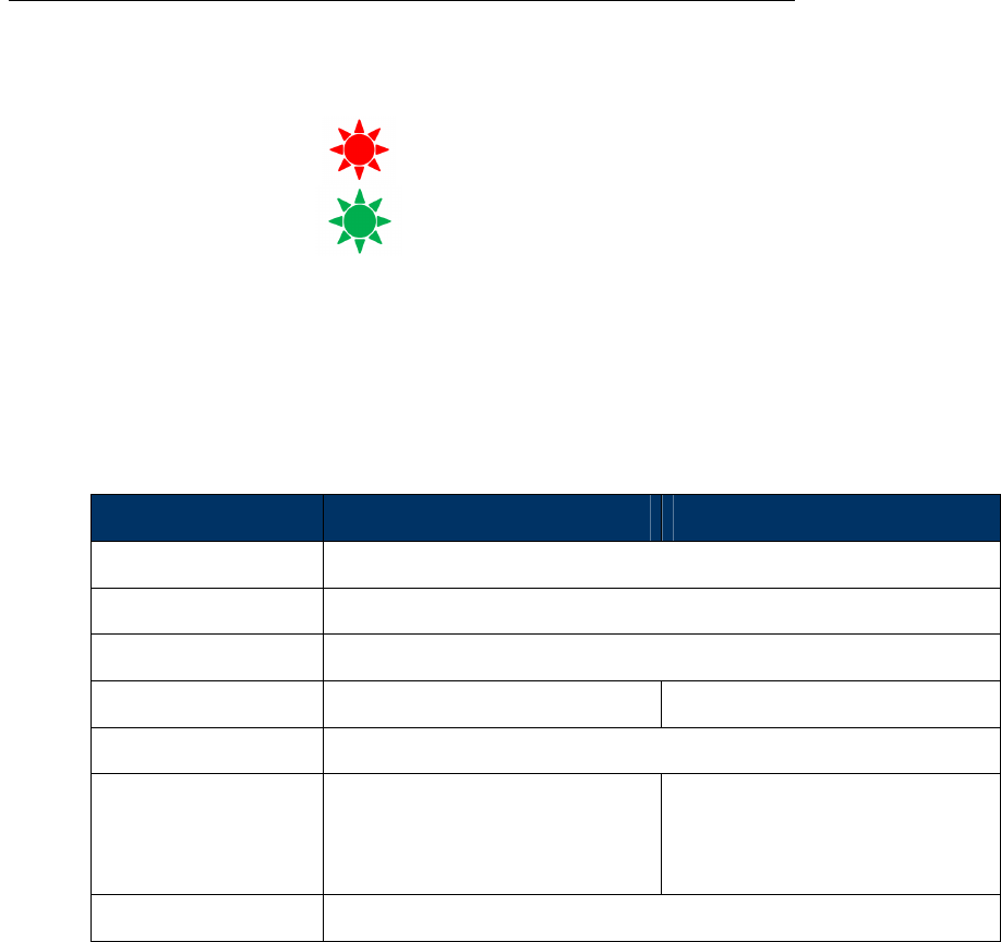
2. LED INDICATORS
Red LED
USB Power indicator
On when powered.
Green LED
Z-Wave communication activity indicator
Blink during z-wave communicating activity.
3. SPECIFICATIONS
Z-Wave & RF Specification
RF EU US
Z-Wave Chip SD3402
Z-Wave Library Serial API
Basic Device Class Static Controller
Z-Wave Protocol Release 6.0.1 Release 6.0.1
Data Rate 9.6kbps / 40kbps / 100kbps
Frequency 9.6 kbps:
40 kbps:
100 kbps:
868.42 MHz
868.40 MHz
869.85 MHz
9.6 kbps:
40 kbps:
100 kbps:
908.42 MHz
908.40 MHz
916.00 MHz
Range Typical 30 meters
UZB Z-Wave USB Adapter
1 1
All information are correct at the time of release. Sigma Designs owns the proprietary rights to the information contained herein this document. It may not be
edited, copied or circulated without prior written agreement by Sigma Designs.
© 2012 Sigma Designs, Inc.
4. PC CONTROLLER APPLICATION SOFTWER INSTALLATION
4.1 Installation
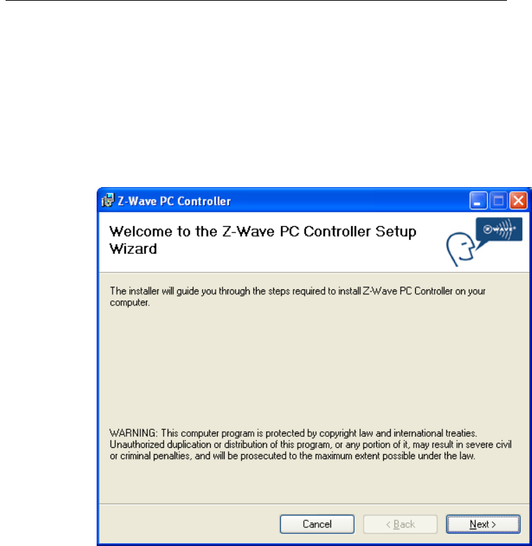
1. Exit all programs.
2. Run the installation file of the Z-Wave PC Controller application.
Figure 1. Welcome page of Z-Wave PC Controller installation
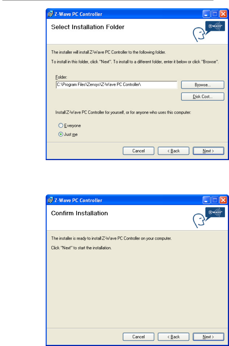
3. Select the installation folder and who should be able to use the Z-Wave PC Controller
application. Please note, that it is not recommended to move the Z-Wave PC Controller
application manually after it has been installed into the above specified folder.
When done, click Next.
UZB Z-Wave USB Adapter
1 1
All information are correct at the time of release. Sigma Designs owns the proprietary rights to the information contained herein this document. It may not be
edited, copied or circulated without prior written agreement by Sigma Designs.
© 2012 Sigma Designs, Inc.
Figure 2. Installation folder
4. Installation confirmation appears. Click Next again to confirm and start the installation.
Figure 3. Confirmation page of Z-Wave PC Controller installation
UZB Z-Wave USB Adapter
1 1
All information are correct at the time of release. Sigma Designs owns the proprietary rights to the information contained herein this document. It may not be
edited, copied or circulated without prior written agreement by Sigma Designs.
© 2012 Sigma Designs, Inc.
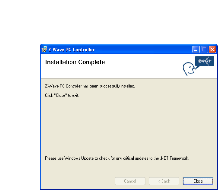
5. The actual installation procedure will pass with progress indicator and final confirmation
appears.
6. Click Close to complete the installation.
Figure 4. Installation complete
UZB Z-Wave USB Adapter
1 1
All information are correct at the time of release. Sigma Designs owns the proprietary rights to the information contained herein this document. It may not be
edited, copied or circulated without prior written agreement by Sigma Designs.
© 2012 Sigma Designs, Inc.
4.2 Start the Z-Wave PC Controller application
You can start the Z-Wave PC Controller using the Start menu. To open the Start menu, click the Start
button in the lower-left corner of your screen. Or, press the Windows logo key on your keyboard. The
Start menu appears.
To open Z-Wave PC Controller, click its icon shown in the left pane of the Start menu that displays the
most frequently used programs list. If you don't see its icon there, click All Programs at the bottom of
the left pane. Instantly, the left pane displays a long list of programs in alphabetical order, followed by a
list of folders. Click Zensys folder, then click Z-Wave PC Controller folder and finally Z-Wave PC
Controller icon.
Each time you start Z-Wave PC Controller, you are actually running the “C:\Program Files\Zensys\Z-
Wave PC Controller\ZWaveController.exe” executable file, although you do not usually type its name or
even see it.
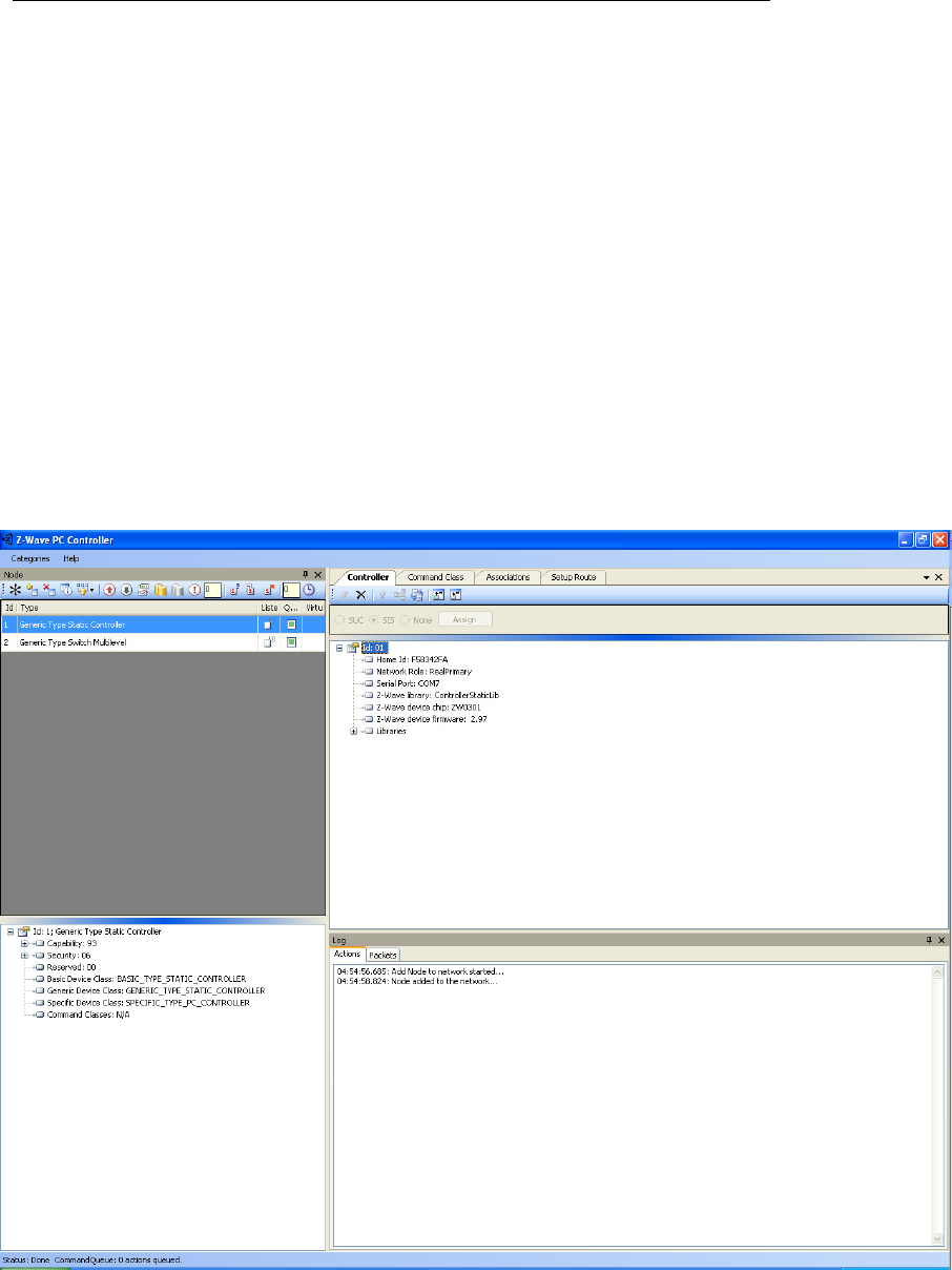
Run the PC based Controller application, and the Main window will appear as shown below:
Figure 5. PC based Controller Main Window

UZB Z-Wave USB Adapter
1 1
All information are correct at the time of release. Sigma Designs owns the proprietary rights to the information contained herein this document. It may not be
edited, copied or circulated without prior written agreement by Sigma Designs.
© 2012 Sigma Designs, Inc.
4.3 Remove Z-Wave PC Controller application Software
You can uninstall Z-Wave PC Controller from your computer if you no longer use it.
1. Open Add or Remove Programs in Control Panel.
To do it, click Start, then click Control Panel (in Classical View – click Start, then point to
Settings, and click Control Panel), and then double-click Add or Remove Programs.
2. Click the program in the list and then click the Remove button. You can sort programs by
selecting different options in Sort by.
3. Standard confirmation dialog appears. Click Yes to continue the removal of the Z-Wave PC
Controller software.
4. Z-Wave PC Controller and its settings will be removed without prompting you further.

UZB Z-Wave USB Adapter
1 1
All information are correct at the time of release. Sigma Designs owns the proprietary rights to the information contained herein this document. It may not be
edited, copied or circulated without prior written agreement by Sigma Designs.
© 2012 Sigma Designs, Inc.
4.4 User Interface
The PC Based Controller application Main window (See Figure 3) is divided into the following views:
• Title bar
• Menu bar
• Node
• Controller
• Command Class
• Associations
• Setup Route
• Node Info
• Log
• Status Bar
4.4.1 Main Menu
On top of the Main window is the Application Main Menu. It has the following items:
Categories Menu
Menu item Description
Node Toggle shows the Node section
Controller Toggle shows the Controller section
Cmd Class Toggle shows the Command Class section
Associations Toggle shows the Associations section
Setup Route Toggle shows the Setup Route section
Log Toggle shows the Log section
Settings
To detect available serial ports and query them to find all
connected Z-Wave devices
Security Test
Schema
Toggle shows the Security Test Schema tab (only in Z-Wave
Security PC Controller)
ERTT Toggle shows the ERTT tab
Exit To exit the application.

UZB Z-Wave USB Adapter
1 1
All information are correct at the time of release. Sigma Designs owns the proprietary rights to the information contained herein this document. It may not be
edited, copied or circulated without prior written agreement by Sigma Designs.
© 2012 Sigma Designs, Inc.
Help menu
Z-Wave Pc Controller comes with its own built-in Help system. The Help menu includes the items to
access this Help system.
Menu item Keyboard Shortcut Description
Index Browses Help system by keywords.
Contents F1 Browses Help system by topics.
Search Opens search tab of the Help system.
About… Displays the version and short status information of
the application
UZB Z-Wave USB Adapter
1 1
All information are correct at the time of release. Sigma Designs owns the proprietary rights to the information contained herein this document. It may not be
edited, copied or circulated without prior written agreement by Sigma Designs.
© 2012 Sigma Designs, Inc.
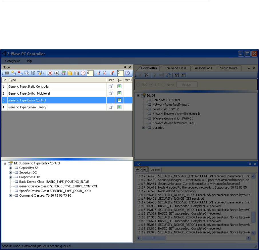
4.4.2 Node View
The Node View contains Menu Bar, Node List and Node information for the selected node.
It is used for operations with nodes.
Figure 6. Node section

UZB Z-Wave USB Adapter
1 1
All information are correct at the time of release. Sigma Designs owns the proprietary rights to the information contained herein this document. It may not be
edited, copied or circulated without prior written agreement by Sigma Designs.
© 2012 Sigma Designs, Inc.
The Node’s Menu Bar has the following items:
Menu item Description
NW Inclusion Network Wide Inclusion, to include all nodes into
network once they have been reset and given power
Add To Add a node
Remove To Remove a node
Node Info To request Node info from a node
Request Node Neighbor Update To get the neighbors from the specified node.
Set SUC/SIS To set the “Set SUC” or “Set SIS” command to the
selected Controller
Basic Set On Send the BASIC SET ON command to Switch a selected
node(s) ON
Toggle Basic Get Starts/stops sending consequent BASIC GET commands
to the selected node(s)
Basic Set Off Sends the BASIC SET OFF command to Switch a selected
node(s) OFF
Switch All On To switch all nodes in the network ON
Switch All Off To switch all nodes in the network OFF
Send NOP ‘No Operation’ – to send a frame not carrying any
functional info to a node
Numeric box after NOP To enter the Node ID of the node to which a NOP frame
is to be sent
Is Failed To send a Failure signal to a node
Replace failed To Replace a failed node
Remove Failed To Remove a failed node
Wake Up Interval (Set) To set up the Wake Up Interval for a non-listening node

UZB Z-Wave USB Adapter
1 1
All information are correct at the time of release. Sigma Designs owns the proprietary rights to the information contained herein this document. It may not be
edited, copied or circulated without prior written agreement by Sigma Designs.
© 2012 Sigma Designs, Inc.
The Node List has three columns:
• Node Id – shows the IDs of all nodes in the network;
• Device Type – shows description of the type of every node in the network;
• Status – shows the current status of a node.
The Node Info section gives structured information about the selected node. For more information,
please refer to Z-Wave Device Class Specification documentation.
UZB Z-Wave USB Adapter
1 1
All information are correct at the time of release. Sigma Designs owns the proprietary rights to the information contained herein this document. It may not be
edited, copied or circulated without prior written agreement by Sigma Designs.
© 2012 Sigma Designs, Inc.
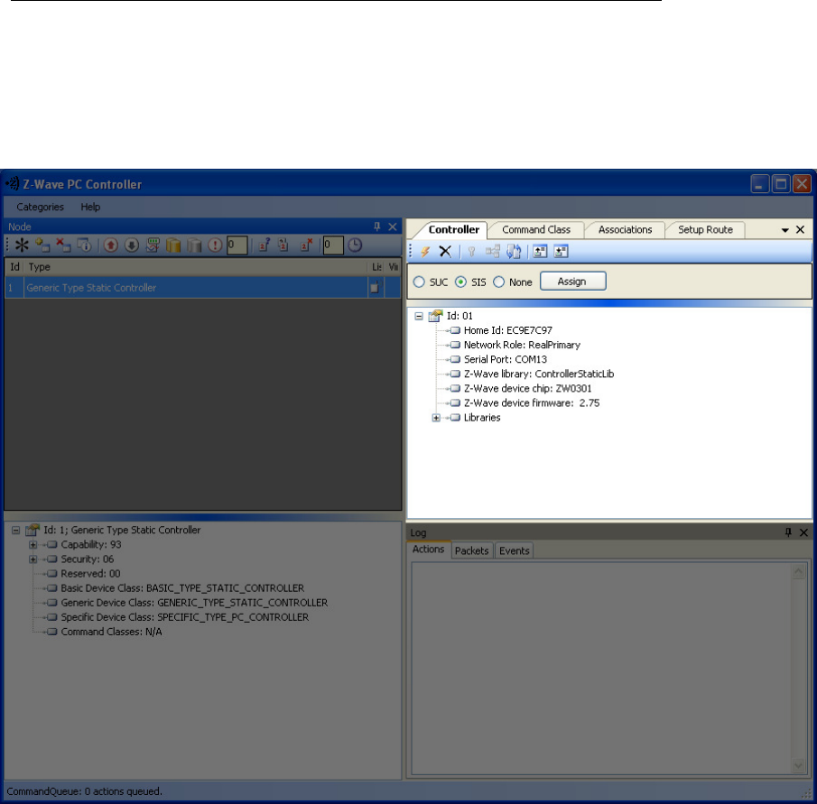
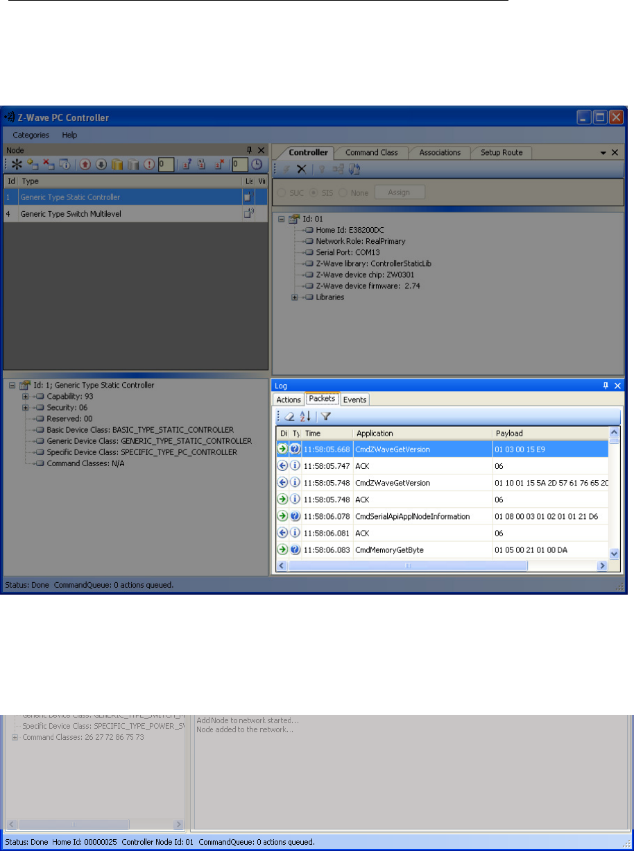
4.4.3 Controller View
The Controller view includes Menu Bar, Network Role Option and Controller Information sections.
The Controller view is used for operations with controllers.
Figure 7. Controller view
The Controller’s Menu Bar has the following items:

UZB Z-Wave USB Adapter
1 1
All information are correct at the time of release. Sigma Designs owns the proprietary rights to the information contained herein this document. It may not be
edited, copied or circulated without prior written agreement by Sigma Designs.
© 2012 Sigma Designs, Inc.
Menu item Description
Start Learn Mode Starts learn mode for the controller if it is needed to include it in another
controller’s network
Reset Resets a controller
Create New Primary A SUC can create a new Primary Controller in the network if the existing
Primary controller fails
Request Update An Inclusion controller can request network updates from a SUC or a SIS
Shift Is used to shift primary role to another controller in the network
Load Command Classes
from device memory
To load command classes from the device memory (previously saved to
device memory)
Save Command Classes
to device memory
To save command classes from the PC Controller application memory to the
Static Controller device memory
The Network Role Option section has controls to assign the role of the SC in the network:
• SUC – Static Update Server
• SIS – Static Update Controller with ID server
• None
General information regarding the SC is displayed in the Controller Information section in the following
items:
Section Description
Controller ID
Displays the node ID
of the PC based SC
Controller Home ID Displays the current Home ID of the PC based SC
Controller Network Role Displays the PC based SC network role
Serial Port Displays the serial port in use.
UZB Z-Wave USB Adapter
1 1
All information are correct at the time of release. Sigma Designs owns the proprietary rights to the information contained herein this document. It may not be
edited, copied or circulated without prior written agreement by Sigma Designs.
© 2012 Sigma Designs, Inc.
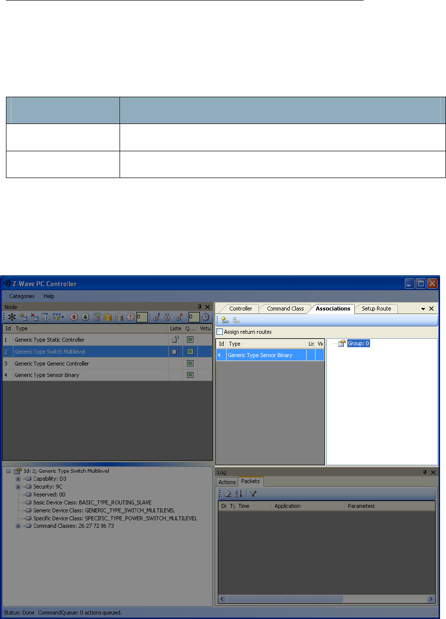
4.4.4 Associations View
The Associations view has a Menu bar, and two fields: Source and Groups. It is used to set up
associations between nodes.
The Menu bar has two items:
Menu item Description
Create Association Creates an association between selected nodes
Remove Association Removes selected association
The Source field shows the list of available source nodes that support the Association command class,
e.g. Binary sensor.
The Groups field shows the association groups that can be or have been created.
The “Assign Return Routes” checkbox is to define whether the Controller should assign return routes
together with setting the association.
Figure 8. Associations view
UZB Z-Wave USB Adapter
1 1
All information are correct at the time of release. Sigma Designs owns the proprietary rights to the information contained herein this document. It may not be
edited, copied or circulated without prior written agreement by Sigma Designs.
© 2012 Sigma Designs, Inc.
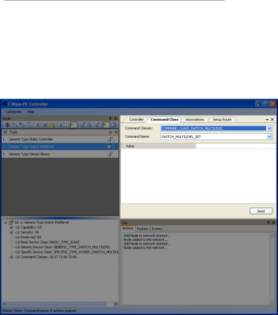
4.4.5 Command Class View
The Command Class view is used to send a specified command class to a selected node. It has the
following items:
• Command Classes: drop-down list to select a command class;
• Command Name: drop-down list to select a command name belonging to the selected class;
• Command Parameters Grid: to enter command parameters.
Figure 9. Command Class view
UZB Z-Wave USB Adapter
1 1
All information are correct at the time of release. Sigma Designs owns the proprietary rights to the information contained herein this document. It may not be
edited, copied or circulated without prior written agreement by Sigma Designs.
© 2012 Sigma Designs, Inc.
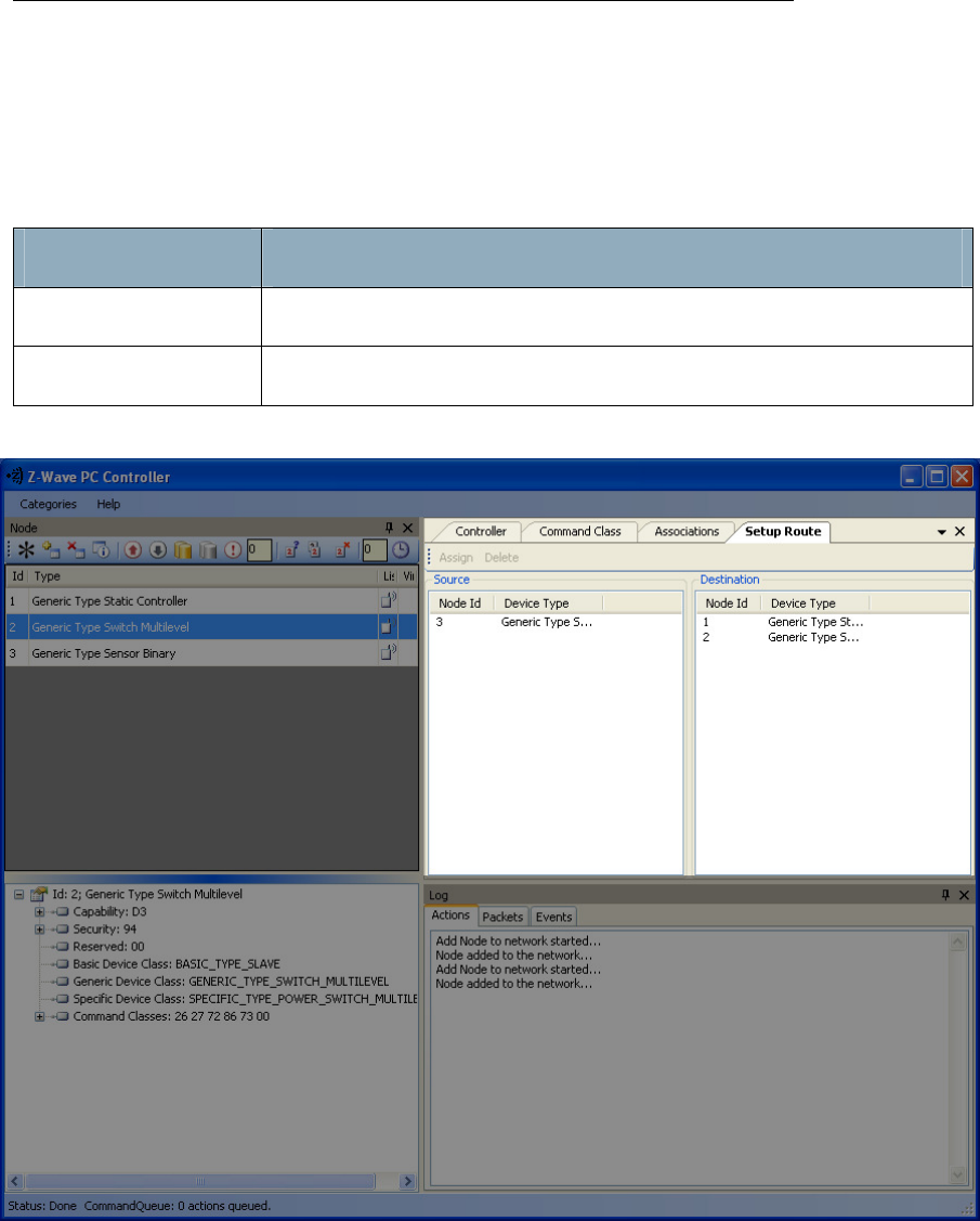
4.4.6 Setup Route View
The Setup Route view has a Menu Bar, Source Node list and Destination Node list. It is used to set up
routes between nodes.
The Menu Bar has two items:
Menu item Description
Assign To assign routes via nodes
Delete To delete assigned routes
Figure 10. Setup Route view
Source Node list and Destination Node list show the lists of source and destination nodes in a routed
network respectively.
UZB Z-Wave USB Adapter
1 1
All information are correct at the time of release. Sigma Designs owns the proprietary rights to the information contained herein this document. It may not be
edited, copied or circulated without prior written agreement by Sigma Designs.
© 2012 Sigma Designs, Inc.
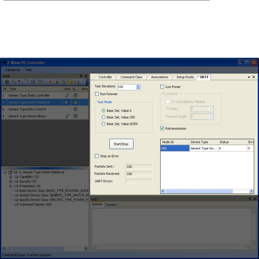
4.4.7
ERTT
Z-Wave PC Controller has the Enhanced Reliability Test Tool implemented. It can be activated as a tab
through the Categories menu or through Ctrl+E keyboard shortcut.
Figure 11. ERTT
UZB Z-Wave USB Adapter
1 1
All information are correct at the time of release. Sigma Designs owns the proprietary rights to the information contained herein this document. It may not be
edited, copied or circulated without prior written agreement by Sigma Designs.
© 2012 Sigma Designs, Inc.
4.4.8
Log View
Here output of current actions is recorded. The two tabs, Actions and Packets, show full information
about what is happening within the PC Controller.
Figure 12. Log View
4.4.9
Log View
Status Bar displays Home ID, controller node ID and Command queue status.
Figure 13. Status Bar

UZB Z-Wave USB Adapter
1 1
All information are correct at the time of release. Sigma Designs owns the proprietary rights to the information contained herein this document. It may not be
edited, copied or circulated without prior written agreement by Sigma Designs.
© 2012 Sigma Designs, Inc.
5. FCC NOTICE TO USERS
Federal Communication Commission Interference Statement
This device complies with Part 15 of the FCC Rules. Operation is subject to the following two conditions:
(1) This device may not cause harmful interference, and (2) this device must accept any interference
received, including interference that may cause undesired operation.
This equipment has been tested and found to comply with the limits for a Class B digital device,
pursuant to Part 15 of the FCC Rules. These limits are designed to provide reasonable protection against
harmful interference in a residential installation. This equipment generates, uses and can radiate radio
frequency energy and, if not installed and used in accordance with the instructions, may cause harmful
interference to radio communications. However, there is no guarantee that interference will not occur
in a particular installation. If this equipment does cause harmful interference to radio or television
reception, which can be determined by turning the equipment off and on, the user is encouraged to try
to correct the interference by one of the following measures:
- Reorient or relocate the receiving antenna.
- Increase the separation between the equipment and receiver.
- Connect the equipment into an outlet on a circuit different from that to which the
receiver is connected.
- Consult the dealer or an experienced radio/TV technician for help.
FCC Caution
Any changes or modifications not expressly approved by the party responsible for compliance could void
the user's authority to operate this equipment.
This transmitter must not be co-located or operating in conjunction with any other antenna or
transmitter.
Radiation Exposure Statement
The product comply with the FCC portable RF exposure limit set forth for an uncontrolled environment
and are safe for intended operation as described in this manual. The further RF exposure reduction can
be achieved if the product can be kept as far as possible from the user body or set the device to lower
output power if such function is available.
The USB dongle transmitter is approved for use in typical laptop and computers. To comply with FCC RF
exposure requirements, it should not be used in other devices or certain laptop and tablet computer
configurations where the USB connectors on the host computer are unable to provide or ensure the
necessary operating configurations intended for the device and its users or bystanders to satisfy RF
exposure compliance requirements.
Note: The country code selection is for non-US model only and is not available to all US model. Per FCC
regulation, all WiFi product marketed in US must fixed to US operation channels only.

UZB Z-Wave USB Adapter
1 1
All information are correct at the time of release. Sigma Designs owns the proprietary rights to the information contained herein this document. It may not be
edited, copied or circulated without prior written agreement by Sigma Designs.
© 2012 Sigma Designs, Inc.
6. EU DECLARATION OF CONFORMITY
EU Declaration of Conformity
This device complies with the essential requirements of the R&TTE Directive 1999/5/EC. The following
test methods have been applied in order to prove presumption of conformity with the essential
requirements of the R&TTE Directive 1999/5/EC:
- EN 60950-1: 2006 + A11: 2009 + A1: 2010
Safety of Information Technology Equipment
- EN300220-2 V2.3.1: (2010-02)
Electromagnetic compatibility and Radio spectrum Matters (ERM); Short Range Devices
(SRD);
Radio equipment to be used in the 25 MHz to 1 000 MHz frequency range with power
levels
- EN 301 489-1 V1.8.1: (2008-04)
Electromagnetic compatibility and Radio Spectrum Matters (ERM);
ElectroMagnetic Compatibility (EMC) standard for radio equipment and services; Part 1:
Common technical requirements
- EN 301 489-3 V1.4.1: (2002)
Electromagnetic compatibility and Radio Spectrum Matters (ERM); ElectroMagnetic
Compatibility (EMC) standard for radio equipment and services; Part 3: Specific
conditions for Short-Range
- EN 50371 V1: (2002-10)
Generic standard to demonstrate the compliance of low power electronic and electrical
apparatus with the basic restrictions related to human exposure to electromagnetic
fields (10 MHz - 300 GHz) -- General public
This device is UZB Z-wave USB Adaptor, intended for use in all EU member states and EFTA countries,
except in France and Italy where restrictive use applies.
In Italy the end-user should apply for a license at the national spectrum authorities in order to obtain
authorization to use the device for setting up outdoor radio links and/or for supplying public access to
telecommunications and/or network services.
This device may not be used for setting up outdoor radio links in France and in some areas the RF output
power may be limited to 10 mW EIRP in the frequency range of 2454 – 2483.5 MHz. For detailed
information the end-user should contact the national spectrum authority in France.
0560
UZB Z-Wave USB Adapter
1 1
All information are correct at the time of release. Sigma Designs owns the proprietary rights to the information contained herein this document. It may not be
edited, copied or circulated without prior written agreement by Sigma Designs.
© 2012 Sigma Designs, Inc.
Česky
[Czech]
[Jméno výrobce] tímto prohlašuje, že tento [typ zařízení] je ve shodě se základními
požadavky a dalšími příslušnými ustanoveními směrnice 1999/5/ES.
Dansk
[Danish]
Undertegnede [fabrikantens navn] erklærer herved, at følgende udstyr [udstyrets
typebetegnelse] overholder de væsentlige krav og øvrige relevante krav i direktiv
1999/5/EF.
Deutsch
[German]
Hiermit erklärt [Name des Herstellers], dass sich das Gerät [Gerätetyp] in
Übereinstimmung mit den grundlegenden Anforderungen und den übrigen
einschlägigen Bestimmungen der Richtlinie 1999/5/EG befindet.
Eesti
[Estonian]
Käesolevaga kinnitab [tootja nimi = name of manufacturer] seadme [seadme tüüp =
type of equipment] vastavust direktiivi 1999/5/EÜ põhinõuetele ja nimetatud
direktiivist tulenevatele teistele asjakohastele sätetele.
English Hereby, [name of manufacturer], declares that this [type of equipment] is in
compliance with the essential requirements and other relevant provisions of
Directive 1999/5/EC.
Español
[Spanish]
Por medio de la presente [nombre del fabricante] declara que el [clase de equipo]
cumple con los requisitos esenciales y cualesquiera otras disposiciones aplicables o
exigibles de la Directiva 1999/5/CE.
Ελληνική
[Greek]
ΜΕ ΤΗΝ ΠΑΡΟΥΣΑ [name of manufacturer] ΔΗΛΩΝΕΙ ΟΤΙ [type of equipment]
ΣΥΜΜΟΡΦΩΝΕΤΑΙ ΠΡΟΣ ΤΙΣ ΟΥΣΙΩΔΕΙΣ ΑΠΑΙΤΗΣΕΙΣ ΚΑΙ ΤΙΣ ΛΟΙΠΕΣ ΣΧΕΤΙΚΕΣ
ΔΙΑΤΑΞΕΙΣ ΤΗΣ ΟΔΗΓΙΑΣ 1999/5/ΕΚ.
Français
[French]
Par la présente [nom du fabricant] déclare que l'appareil [type d'appareil] est
conforme aux exigences essentielles et aux autres dispositions pertinentes de la
directive 1999/5/CE.
Italiano
[Italian]
Con la presente [nome del costruttore] dichiara che questo [tipo di apparecchio] è
conforme ai requisiti essenziali ed alle altre disposizioni pertinenti stabilite dalla
direttiva 1999/5/CE.
Latviski
[Latvian]
Ar šo [name of manufacturer / izgatavotāja nosaukums] deklarē, ka [type of
equipment / iekārtas tips] atbilst Direktīvas 1999/5/EK būtiskajām prasībām un
citiem ar to saistītajiem noteikumiem.
Lietuvių Šiuo [manufacturer name] deklaruoja, kad šis [equipment type] atitinka esminius
UZB Z-Wave USB Adapter
1 1
All information are correct at the time of release. Sigma Designs owns the proprietary rights to the information contained herein this document. It may not be
edited, copied or circulated without prior written agreement by Sigma Designs.
© 2012 Sigma Designs, Inc.
[Lithuanian]
rei
kalavimus ir kitas 1999/5/EB Direktyvos nuostatas.
Nederlands
[Dutch]
Hierbij verklaart [naam van de fabrikant] dat het toestel [type van toestel] in
overeenstemming is met de essentiële eisen en de andere relevante bepalingen van
richtlijn 1999/5/EG.
Malti
[Maltese]
Hawnhekk, [isem tal-manifattur], jiddikjara li dan [il-mudel tal-prodott] jikkonforma
mal-ħtiġijiet essenzjali u ma provvedimenti oħrajn relevanti li hemm fid-Dirrettiva
1999/5/EC.
Magyar
[Hungarian]
Alulírott, [gyártó neve] nyilatkozom, hogy a [... típus] megfelel a vonatkozó alapvetõ
követelményeknek és az 1999/5/EC irányelv egyéb elõírásainak.
Polski
[Polish]
Niniejszym [nazwa producenta] oświadcza, że [nazwa wyrobu] jest zgodny z
zasadniczymi wymogami oraz pozostałymi stosownymi postanowieniami Dyrektywy
1999/5/EC.
Português
[Portuguese]
[Nome do fabricante] declara que este [tipo de equipamento] está conforme com os
requisitos essenciais e outras disposições da Directiva 1999/5/CE.
Slovensko
[Slovenian]
[Ime proizvajalca] izjavlja, da je ta [tip opreme] v skladu z bistvenimi zahtevami in
ostalimi relevantnimi določili direktive 1999/5/ES.
Slovensky
[Slovak]
[Meno výrobcu] týmto vyhlasuje, že [typ zariadenia] spĺňa základné požiadavky a
všetky príslušné ustanovenia Smernice 1999/5/ES.
Suomi
[Finnish]
[Valmistaja = manufacturer] vakuuttaa täten että [type of equipment = laitteen
tyyppimerkintä] tyyppinen laite on direktiivin 1999/5/EY oleellisten vaatimusten ja
sitä koskevien direktiivin muiden ehtojen mukainen.
Svenska
[Swedish]
Härmed intygar [företag] att denna [utrustningstyp] står I överensstämmelse med de
väsentliga egenskapskrav och övriga relevanta bestämmelser som framgår av
direktiv 1999/5/EG.