Sigma S2Ba Users Manual BA_SI_018_10_03_GB
S2Ca to the manual 766ed1ff-02c3-4c61-9ec5-2d7f35404fa2
2015-01-05
: Sigma Sigma-S2Ba-Users-Manual-204150 sigma-s2ba-users-manual-204150 sigma pdf
Open the PDF directly: View PDF ![]() .
.
Page Count: 63
Part No. 987282 ProMinent Dosiertechnik GmbH ·69123 Heidelberg ·Germany BA SI 018 10/03 GB
ProMinent
®
Please completely read through these operating instructions first! · Do not discard!
The warranty shall be invalidated by damage caused by operating errors!
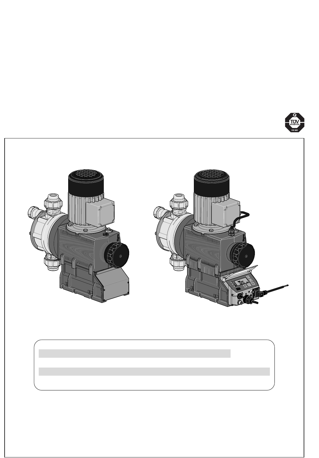
Two sets of operating instructions are necessary to ensure the ProMinent® Sigma/ 2 S2Ba or S2Ca metering pumps
are operated safely and reliably for their intended purpose:
This product specific Sigma/ 2 operating instructions manual and the ”General operating instructions
ProMinent® motor-driven metering pumps and hydraulic accessories” are only valid if read together!
Operating Instructions
ProMinent® Sigma/ 2
S2Ba (Basic Type)
S2Ca (Control Type)
START
STOP
S2Ba S2Ca
Please enter the identity code of the device here.
S2Ba ___ ___ ___ ___ ___ ___ ___ ___ ___ ___ ___ ___
S2Ca ___ ___ ___ ___ ___ ___ ___ ___ ___ ___ ___ ___ ___ ___ ___
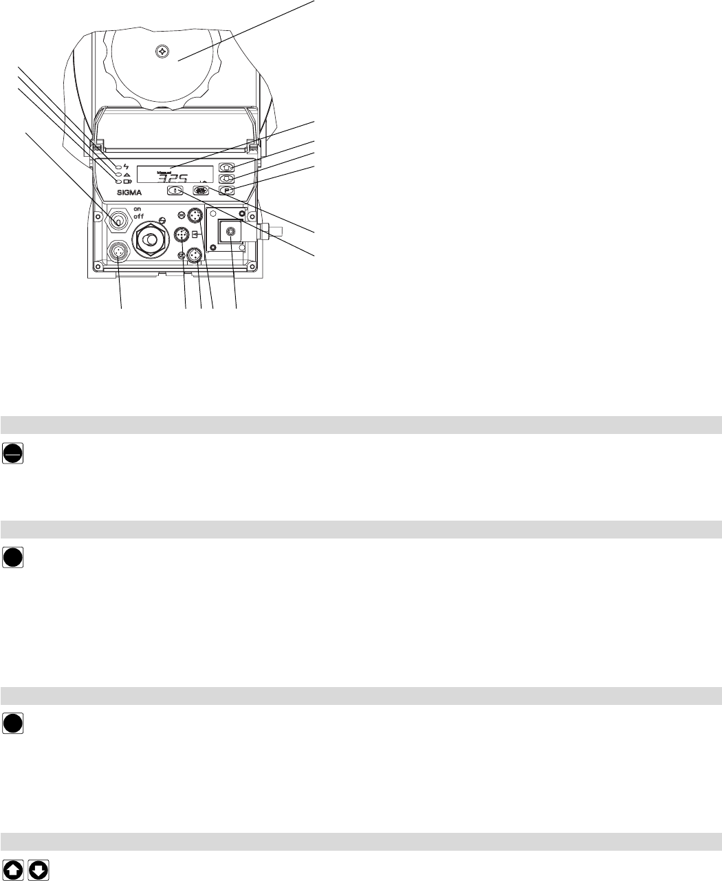
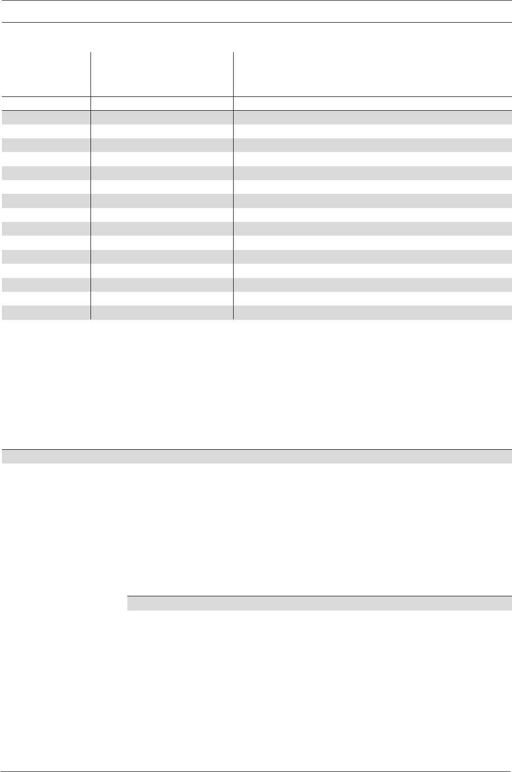
Control elements: overview
1Operating light (green)
2Warning light (yellow)
3Error warning light (red)
4Stroke length adjuster
5LCD display
6UP key
7DOWN key
8P key
9STOP/START key
10 i key
11 Relay output (optional)
12 Metering monitor socket
13 Float switch socket
14 External control socket
15 Diaphragm rupture indicator socket
16 Mains switch
Key functions
In continuous display mode In settings mode
(operating) (settings)
STOP/START key
STOP
START
Press briefly Stop pump, Stop pump,
start pump start pump
P key
P
Press briefly Start batch (in “batch” operating mode only), Confirm entry- jump to next menu
Cancel error option or continuous display
Press for 2 s Change to settings mode ---
Press for 3 s --- Jump to continuous display
Press for 10 s Software version displayed
Press for 15 s Load factory settings (calibration) ---
i key
i
Press x1 Toggle between continuous displays Toggle between “change individual digits”
and change a figure"
Press x2 --- For “change individual digits”:
jumps to first digit
Arrow keys UP and DOWN
Press separately Change directly alterable values Select other settings,
(until “Set” appears) change individual digit or figure
Press simultaneously Prime (in “stroke rate” permanent display) ---
Control elements and key functions
1
2
3
16
4
9
10
8
5
6
7
15 14 13 12 11
P
P
PPPP
P
P
P
P
PP
P
PP
P
PP
P
P
P
P
P
P
P
P
P P
P
P
i
STOP
STOP
START
START
Batch
Contact
ManualAnalog
Analog
Manual
Contact
Batch
Set
mA
Set
Analog
mA
Set
Analog
Set
Analog
mA
Set
Analog
mA
Set
Analog
Freq.
Set
Analog
Freq.
Set
Analog
Freq.
Set
Analog
Freq.
Set
Analog
Freq.
Set
Analog
Freq.
Set
Analog
Freq.
Set
Analog
Freq.
Set
Analog
Freq.
Set
Analog
Freq.
Set
Analog
Freq.
Set
Analog
Freq.
Set
Analog
mA
Set
Analog
mA
Set
Analog
mA
Set
Analog
mA
Set
Analog
mA
Set
Analog
mA
Set
Analog
mA
Set
Analog
mA
Set
Analog
mA
Set
Analog
mA
Set
Analog
Set
Analog
Set
Analog
2 s
Set
Analog
Set
Analog
Set
Analog
2
1
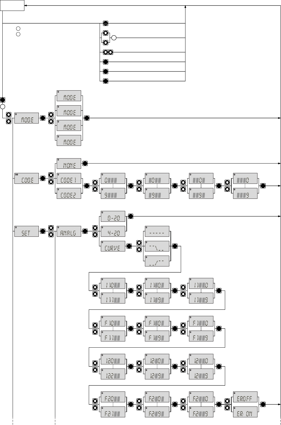
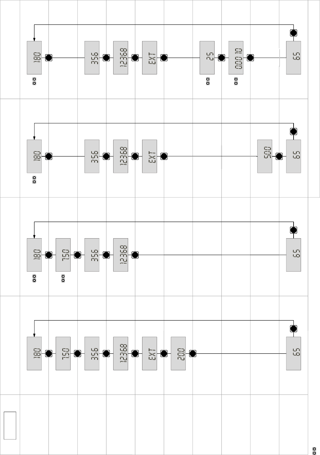
Operating-/Settings Diagram
Continuous
display
Start/stop pump
Change directly alterable values
= Lock (CODE 1)
= Lock (CODE 2)
Prime
Start batch (in"batch" operating mode only)
Cancel error
Check adjustable values
2
1
p. 45
p. 52
p. 44
p. 51
next page
Select the operating mode here first,
then carry out the settings in the SET menu.
Exceptions: Timer and PROFIBUS®.
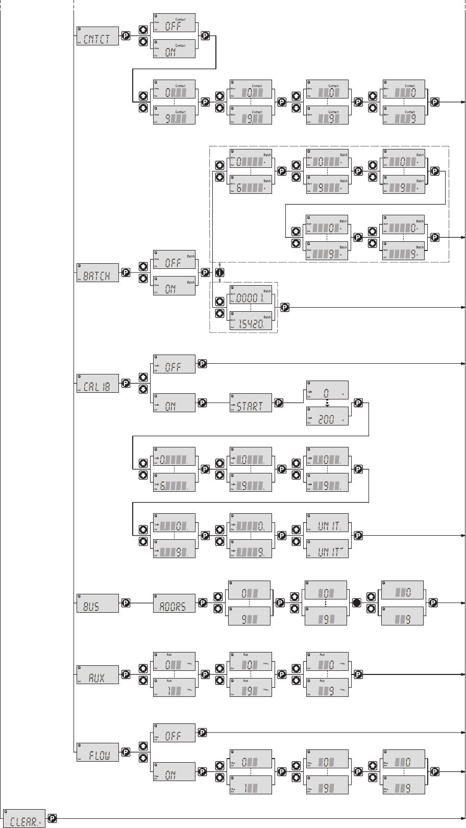
Set
P
Set
Set
Set
Calib
Set
Calib
Set
Set
Set
p. 51
p. 49
p. 51
p. 49
p. 50
p. 34
p. 51
previous page
i
i
i
i
i
i
i
i
i
i
i
i
i
i
i
i
i
i
i
i
i
i
i
i
i
i
i
N
*
Mem
Contact
Stop
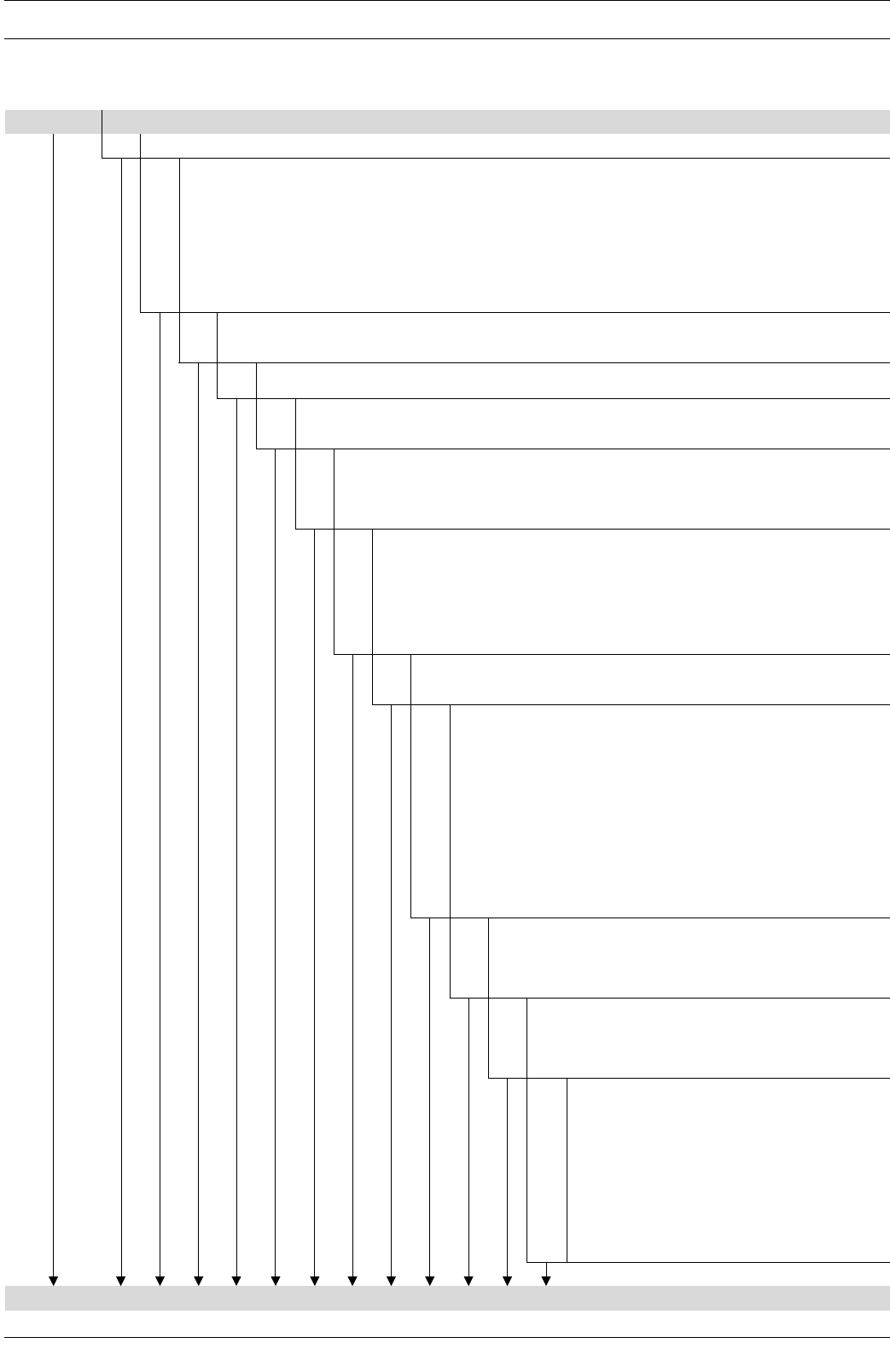
Operating mode "Analog" 0-20 mA
Stroke rate
Feed rate
Total stroke number
Total litres
(feed quantity)
"External" display
Signal current
Strokes remaining
Batch size/
Litres remaining
Factor
"Mem" appears only when "memory" function activated
Stroke length
Operating mode "Manual"
Continuous display
Operating mode "Contact" with
memory and tansfer factor 5
Operating mode "Batch" with
memory and tansfer factor 5
N
Analog
Stop
L
Analog
Stop
Analog
Stop
mA
Analog
Stop
%
Analog
Stop
%
Manual
Stop
%
Contact
Stop
%
Batch
Stop
Freq.
Manual
Stop
Freq.
Contact
Stop
N
Stop
Contact
Freq.
Batch
Stop
N
Stop
Batch
/hL
Manual
Stop
N
Stop
Manual
L
Stop
Contact
L
Stop
Batch
L
Stop
Manual
Stop
Contact
Mem
Stop
Batch
Mem
N
*
Mem
Batch
Stop
L
*
Mem
Batch
Stop
*
Mem
Batch
Stop
*
Mem
Contact
Stop
Freq.
Analog
Stop
/hL
Analog
Stop
Continuous
display
= UP and/or DOWN arrow keys, directly alterable values
Operating mode ”Contact” with
memory and transfer factor 5
Operating mode ”Batch” with
memory and transfer factor 5

Page 6 ProMinent®
Dulcodes UV-Desinfektionsanlage
Imprint
Operating Instructions for ProMinent® Sigma/ 2 S2Ba/S2Ca
© ProMinent Dosiertechnik GmbH, 2002
ProMinent Dosiertechnik GmbH
Im Schuhmachergewann 5-11
69123 Heidelberg · Germany
info@prominent.de
www.prominent.de
Subject to technical modifications.
Imprint

Dulcodes UV-Desinfektionsanlage
Page 7
ProMinent®
Table of contents
Page
Device Identification/Identcode 9
1Notes on safety of ProMinent® metering pumps 11
1.1 Summary of additional safety instructions for the EX version
of the pump (in accordance with ATEX) 11
1.2 General notes 13
1.3 Notes on installation, start-up and operation 13
1.4 Notes on maintenance and repair 14
2Product description S2Ba/S2Ca 15
2.1 Identification of pump type 15
2.2 Design/Functional description 15
2.2.1 Functional description, drive 15
2.2.2 Stroke movement 16
2.2.3 Metering capacity diagram 17
2.2.4 Functional description, delivery unit 19
2.2.5 Integrated overflow valve with bleeder function 20
2.2.6 Diaphragm rupture sensor 22
3Technical data 25
3.1 Technical data Sigma/ 2 25
3.1.1 Capacity data 25
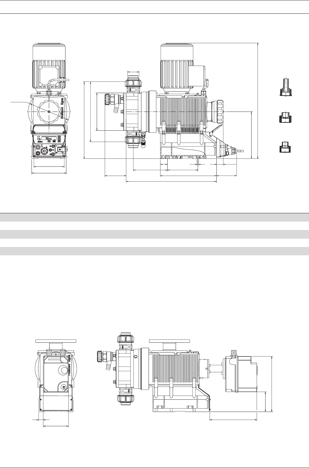
3.1.2 Dimensions Sigma/ 2 27
3.1.3 Dimensions Sigma/ 2 with stroke adjustment motor 27
3.1.4 Motor data 28
3.1.5 Stroke actuator drive mechanism 28
3.1.6 Stroke adjuster drive mechanism 28
3.1.7 Electrical data, stroke sensor “Sigma”28
3.1.8 Electrical data, pacing relay “Sigma”29
3.1.9 Sound intensity level 29
4Start-up/Maintenance 30
4.1 Start-up 30
4.2 Maintenance 30
4.3 Replacement of wearing parts 31
5Features of the S2Ca metering pumps 33
5.1 Function description, motors 33
5.2 Function description, controller 33
5.3 Sockets, symbols and wiring diagram 35
5.4 Retrofitting relays 41

Page 8 ProMinent®
Dulcodes UV-Desinfektionsanlage
Table of contents
6Control elements 42
7Settings 43
7.1. Check adjustable values 44
7.2 Change to settings mode 44
7.3 Select operating mode (MODE menu) 44
7.4 Settings for operating mode (SET menu) 45
7.4.1 Settings for “manual” operating mode 45
7.4.2 Settings for “analogue” operating mode (ANALG menu) 45
7.4.3 Settings for “contact” operating mode (CONTCT menu) 47
7.4.4 Settings for “batch” operating mode (BATCH menu) 49
7.5 Settings for programmable functions (SET menu) 50
7.5.1 Settings for “calibration” function (CALIB menu) 50
7.5.2 Settings for “auxiliary frequency” function (AUX menu) 51
7.5.3 Settings for the “flow” function (FLOW menu) 51
7.6 Setting code (CODE menu) 51
7.7 Cancel total stroke number or total litres (CLEAR window) 51
8Operating 52
8.1 Manual operation 52
8.2 Remote control 53
9Troubleshooting 53
10 Decommissioning and disposal 55
11 Spare parts and accessories 56
Annex 57
Motor data sheet 57
EC Declaration of Conformity 58
Exploded diagrams of liquid ends 59
Stroke actuator wiring diagram 63
Wiring diagram, stroke length adjuster 63
Dulcodes UV-Desinfektionsanlage
Page 9
ProMinent®
Dulcodes UV-Desinfektionsanlage Identcode ordering system
ProMinent®
Identcode ordering system
Please enter the identcode on the device label into the grey box below.
S2Ba Sigma Basic Type (S2Ba)
HM Main drive, diaphragm
Pump type: (figures 1+2 = back pressure [bar], figures 3-5 = feed rate [l/h])
16050
16 bar; 50 l/h
16090
16 bar; 90 l/h
16130
16 bar; 130 l/h
12050*
10 bar; 48 l/h
12090*
10 bar; 86 l/h
12030*
10 bar; 125 l/h
07120
7 bar; 120 l/h
07220
7 bar; 220 l/h
04350
4 bar; 350 l/h * for SST versions, max. 12 bar
Liquid end materials:
PV PVDF
SS Stainless steel
Seal material:
TPTFE seal
Diaphragm:
0Standard diaphragm, PTFE version
1Double diaphragm with diaphragm rupture indicator (retro fit possible)
Liquid end version:
0No spring
1With 2 valve springs, Hastelloy C, 0.1 bar
4With pressure relief valve, Viton® seal, no valve spring
5With pressure relief valve, Viton® seal, and valve spring
Hydraulic connection:
0Standard threaded connector (according to technical data)
1Union nut and PVC insert
2Union nut and PP insert
3Union nut and PVDF insert
4Union nut and stainless steel insert
7Union nut and PVDF hose nozzle
8Union nut and stainless steel hose nozzle
Version:
0With ProMinent® logo (standard)
1Without ProMinent® logo
Electrical power supply:
S3 ph, 230 V/400 V 50/60 Hz, 0.18 kW
M1 ph, AC, 230 V/50/60 Hz, 0.18 kW
N1 ph, AC 115 V 60 Hz, 0.18 kW
L3 ph, 230 V/400 V, 50 Hz, (EExe, EExde)
P3 ph, 230 V/400 V, 60 Hz, (EExe, EExde)
R3 ph, variable speed motor, 230/400 V, 0.37 kW
VVariable speed motor with integrated speed control 1 pH,
230 V, 50/60 Hz
Z1 ph, variable speed control set 1 ph, 230 V, 50/60 Hz
1No motor, with B14 flange (Gr. 71 (DIN))
2 No motor, C 56 flange (NEMA)
3No motor, B5 Gr. 63 (DIN)
4No motor, B5, Gr. 70 (DIN)
Motor version:
0IP 55 (standard)
1Exe version (II 2G EExe II T3)
2Exde version (II 2G EExde IIC T4)
AATEX type drive
Stroke sensor:
0No stroke sensor (standard)
1with stroke sensor (Hall sensor, no connection cable)
2Pacing relay (reed relay)
3Stroke sensor (Namur) intrinsically safe
Stroke length adjustment:
0Manual (standard)
1With stroke positioning motor, 230 V/50/60 Hz
2With stroke positioning motor, 115 V/50/60 Hz
3With stroke control motor,
0...20 mA 230 V/50/60 Hz
4With stroke control motor
4...20 mA 230 V/50/60 Hz
5With stroke control motor
0...20 mA 115 V/50/60 Hz
6With stroke control motor
4...20 mA 115 V/50/60 Hz
S2Ba ___ ___ ___ ___ ___ ___ ___ ___ ___ ___ ___ ___
Viton® is a registered trademark of DuPont Dow Elastomers.
Page 10 ProMinent®
Dulcodes UV-Desinfektionsanlage
Identcode ordering system
Identcode ordering system
Please enter the identcode on the device label into the grey box below.
S2Ca Sigma Control Type (S2Ca)
HM Power end, diaphragm
Pump typ: (figures 1+2 =back pressure [bar],figures 3-5 =feed rate [l/h])
16050
16 bar; 60 l/h
16090
16 bar; 95 l/h
16130
16 bar; 136 l/h
12050* 10 bar; 60 l/h
12090* 10 bar; 95 l/h
12130* 10 bar; 136 l/h
07120
7 bar; 148 l/h
07220
7 bar; 232 l/h
04350
4 bar; 350 l/h * for SST versions, max. 12 bar
Liquid end materials:
PV PVDF
SS Stainless steel
Seal material:
TPTFE seal
Displacement element:
0Standard diaphragm
1Double diaphragm with rupture indicator incorporating “Pump stopping” function
2Double diaphragm with rupture indicator incorporating “Pump alarm” function
Liquid end version:
0No springs
1With 2 valve springs,Hastelloy C,0.1 bar
4With relief valve,Viton
®
seal,no valve spring
5With relief valve,Viton
®
seal,with valve spring
Hydraulic connection:
0Standard threaded connector (according to technical data)
1Union nut and PVC insert
2Union nut and PP insert
3Union nut and PVDF insert
4Union nut and stainless steel insert
7Union nut and PVDF hose nozzle
8Union nut and stainless steel hose nozzle
Version:
0With ProMinent® logo
1Without ProMinent® logo
Electrical power supply:
U1 ph 100-230 V ±10 %, 50/60 Hz
Cable and plug:
A2 m European
B2 m Swiss
C2 m Australian
D2 m USA
Relays:
0No relay
1With fault indicating relay (N/C)
3 With fault indicating relay (N/O)
4As 1 with pacing relay
5As 3 with pacing relay
FPower relay N/C
GPower relay N/O
Control variant:
0Manual + external with pulse control
1Manual + external + pulse control
+ analogue
4As 0 + process-timer
5As 1 + process-timer
P PROFIBUS®
Access code:
0No access code
1With access code
Metering monitor:
0 Input with pulse evaluation
1Input with permanent contact
evaluation
Stroke length
adjustment:
0Manual
CManual + calibration
S2Ca ___ ___ ___ ___ ___ ___ ___ ___ ___ ___ ___ ___ ___ ___ ___
Viton® is a registered trademark of DuPont Dow Elastomers.
Dulcodes UV-Desinfektionsanlage
Page 11
ProMinent®
Notes on safety of ProMinent® metering pumps
1Notes on safety of ProMinent® metering pumps
General user instructions
Please read through the following user instructions carefully! They will help you get the best use
out of the operating instruction manual.
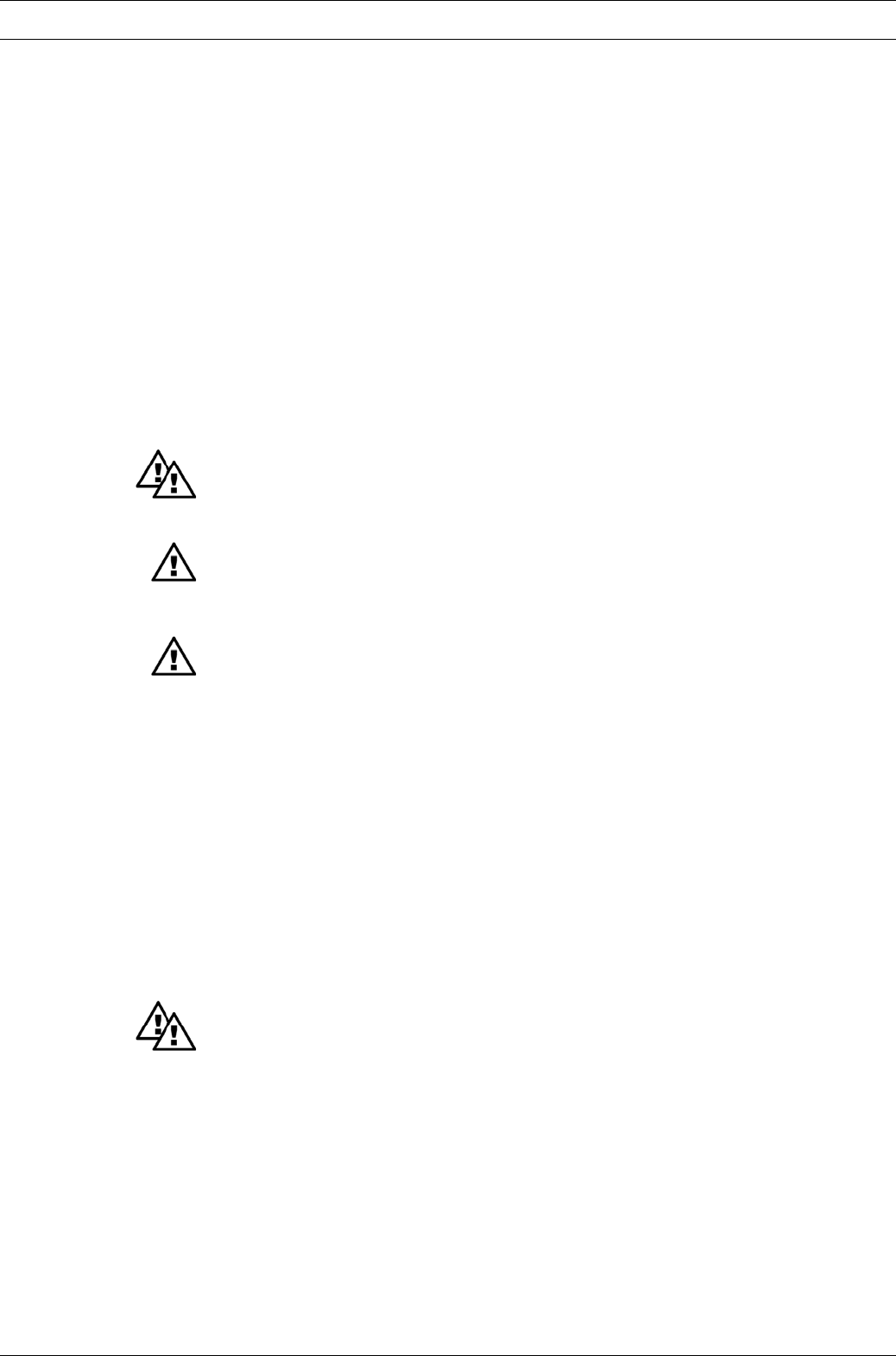
The following are highlighted in the text:
•Enumerations
왘Instructions
Operating guidelines:
NOTE
Notices are intended to make your work easier.
and safety guidelines:
WARNING
Describes a potentially dangerous situation. If not avoided. could cause fatal or serous
injury.
CAUTION
Describes a potentially dangerous situation. If not avoided. could cause slight or minor
injury or damage to property.
IMPORTANT
Describes a potentially damaging situation. If not avoided. could cause damage to
property.
Please also note the guidelines in “General Operating Instruction Manual for ProMinent® Motor-
Driven Metering Pumps and Hydraulic Accessories”!
EX-pump only: The nameplates affixed to the title page are identical to those on the pump
supplied to enable clear identification on the correct operating instruction manual for the pump.
Please give the order number and the serial number, which you will find on the nameplates of the
pump itself, in the event of any query or spare part order. This facilitates identification of the
pump.
1.1 Summary of additional safety instructions for the EX version
of the pump (in accordance with ATEX)
WARNING
•In explosion-threatened workplaces in zone 1, device category II 2G of explosion group II C
the pump may not be operated without the corresponding rating plate (and the corre-
sponding EC conformity declaration) for pumps for explosion-threatened workplaces in
accordance with guideline 94/9/EC of the European guidelines.
•From July 1st, 2003 on, only pumps with the corresponding marking according to EC-Ex-
directive 94/9 may be used in industrial premises with potentially explosive atmospheres.
The explosion group, category and type of protection shown on the marking must
correspond to or exceed the conditions prevailing in the intended area of application.
•All other uses or modifications are prohibited!
•Pumps may never be operated in explosion-threatened workplaces without a correspond-
ing rating plate (and the corresponding EC conformity declaration) for pumps for
explosion-threatened workplaces.

Page 12 ProMinent®
Dulcodes UV-Desinfektionsanlage
Notes on safety of ProMinent® metering pumps
•Installations in potentially explosive atmospheres must be inspected by an “accredited
qualified” person. This applies in particular also for intrinsically safe electrical circuits.
• Drive motors must be secured by an appropriate motor protection switch. A motor
protection approved for this application must be used for Ex“e”-motors. (Protection
against heating due to overload)
•Observe all relevant standards e.g. DIN EN 60079, DIN EN 50020, DIN VDE 0165 and/or
DIN VDE 0118 “Installing electrical equipment in explosion-threatened areas”!
•When installing the metering pump, observe the directives for the installation of devices
in explosion-threatened areas, e.g. for Europe the European operator’s guideline 99/92/EC
(ATEX137)*, (in Germany implemented via the new operating safety ordinance (Official
Federal Gazette for 2002, Part 1, No. 70, issued in Bonn 2.10.2002))!
* previously ElexV
•Observe documents supplied with individual electric components!
•On principle, metering pumps in potentially explosive atmospheres must be equipped
with a safety overflow valve at the outlet side of the pump (serves as protection against
overheating due to overload and against sparks produced by shock due to overload
which has led to the breakage drive parts.)
•When using with flammable media:
-Diaphragm pumps with mechanically actuated diaphragm: no additional measures
necessary, however, version with diaphragm rupture indicator, version Ex“i”*, must be
used on principle.
-For all metering pumps for metering inflammable media applies: starting up and
emptying only supervised by a competent person.
-Inflammable media may only be lifted with stainless steel liquid ends. - For exceptional
cases, where this is not possible, also PTFE with carbon may be used, our versions TT_
are made of conductive plastics. In this case, special attention must be paid by the
user due to the lower mechanical stability.
• If using the metering pump for Europe e.g. the European operator’s guideline 99/92/EC*
(ATEX 137**), (in Germany implemented via the new operating safety ordinance (Official
Federal Gazette for 2002, Part 1, No. 70, issued in Bonn 2.10.2002) and the German
dangerous chemicals ordinance))!
* previously Ex Vo, Vb F
** previously ATEX118A
•Observe also all relevant standards e.g. DIN EN 60079-10/14 and DIN EN 50020 for
installations in explosion-threatened areas!
•Note all national directives which apply to the installation!
•Wear parts (diaphragms, bearings etc.) of metering pumps used in potentially explosive
atmospheres must be replaced after having completed 90% of their nominal product life.
•The lubricant supply must be regularly checked for lubricated pumps, for instance by
checking the fill level, visual inspection for leakages etc.
•The proper general function, in particular of the drive, must be safeguarded by regular
inspections (leakages, noises, temperatures, possible discoloration due to excess
temperatures....).
•Use original spare parts should exchange become necessary!
•Check that the pressure relief valve downstream from the pump is functioning correctly!
The pressure relief valve must prevent the gearbox from being overloaded and over-
heating in explosion-threatened workplaces!
•When cleaning plastic parts, attention must be paid to not generating any electrostatic
charge by rubbing excessively. - see danger sign.
•These measures are the minimum protection measures specified by ProMinent. Should
the user know about any further risks, it is his duty to eliminate them by taking
corresponding measures.
Dulcodes UV-Desinfektionsanlage
Page 13
ProMinent®
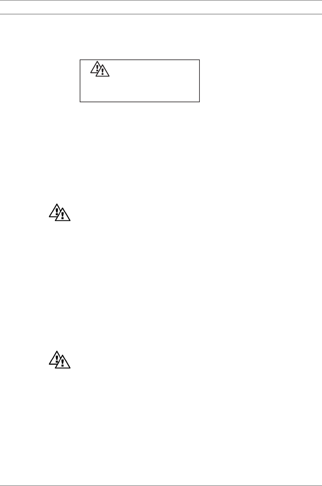
Safety devices
The following safety notice must be affixed to the pump (with PP, PC and PV liquid ends, acrylic
glass cover, ...)
Because of danger of electrostatical
ignition use damp cloth only
for wiping plastic parts!
ATTENTION
EC conformity declaration / certificates
The EC conformity declaration for pumps for explosion-threatened workplaces is supplied with
the pump (the copy of the EC conformity declaration for the pump itself does not apply to pumps
designed for explosion-threatened workplaces).
The EC conformity declarations, the EC series prototype test reports and the operating manuals
for the individual components are also supplied with the pump.
1.2 General notes
WARNING
•The equipment/devices may only be used for their intended purpose.
•ProMinent® metering pumps must not be assembled with parts which are not tested and
recommended by ProMinent otherwise this can lead to injury to persons and damage to
property for which no liability will be accepted!
•Pumps must be accessible at all times to facilitate operation and maintenance. Access
points must not be obstructed or blocked!
•Before carrying out any maintenance and repair work always drain off and flush out the
liquid end first if hazardous or unknown metered media are used!
• When metering hazardous or unknown liquids, always wear safety clothing (safety
goggles, gloves, ...) when working on the liquid end!
•You must observe the guidelines in this operating instructions manual and the ”General
operating instructions manual for ProMinent
®
motor-driven metering pumps and hydraulic
accessoires” on assembly, installation and maintenance!
1.3 Notes on installation, start-up and operation
WARNING
•The metering pump can contain water residue in the liquid end as the result of testing at
the factory!
If handling media which must not come in contact with water, all traces of water must be
removed from the liquid end before start-up! For this purpose, turn the pump through
180˚ and drain off the liquid end then flush with a suitable medium from above via the
intake connection!
•Do not connect mains voltage to the control cable!
• When operating the metering pump against a closed shut-off element on the pressure
side or in the event of pressure peaks during the metering stroke, the system pressure
can reach a multiple of the maximum permissible operating pressure that can conse-
quently cause the pressure line to burst!
•To avoid this situation, an overflow is recommended for the purpose of limiting the
maximum permissible operating pressure of the pump or system.
•Do not connect a metal bypass line to the overflow valve on the PVT delivery unit! This
could cause cracks in the delivery unit!
Notes on safety of ProMinent® metering pumps
Page 14 ProMinent®
Dulcodes UV-Desinfektionsanlage
IMPORTANT
•Set stroke length only with pump in operation!
•Pull the red plug for venting the gear unit during initial operation of the Sigma/ 2 metering
pump (refer to Fig. 2, item 10)!
NOTE
• The pump must be secured in such a way that no vibrations can occur! The valves of the
liquid end must always be positioned vertically in order to ensure trouble-free operation!
•The intake and delivery lines must always be arranged such as to ensure connection at
the liquid end is free of mechanical stress!
The lines must be secured such that no vibrations can occur!
•Only use the clamping rings and hose sockets intended for the relevant hose diameter as
well as original hoses with the specified hose dimensions and wall thickness otherwise
the stability and durability of the connection will not be guaranteed!
Avoid reducing hose sizes!
Observe the permissible pressure of the hoses!
•A vent with return to the supply tank is advisable when metering extremely aggressive or
hazardous media!
In addition, a shut-off valve should be provided on the delivery or intake side!
1.4 Notes on maintenance and repair
WARNING
•Only specially trained and authorized persons are permitted to carry out maintenance on
metering pumps and their peripherals!
•If hazardous or unknown metering media are used, always flush out the liquid end first
before carrying out any maintenance and repair work!
• When metering hazardous or unknown liquids, always wear safety clothing (safety
goggles, gloves, ...) when working on the liquid end!
• Always depressurize the delivery line first before carrying out any work on the pump!
Always discharge and flush liquid end!
Observe safety data sheets for metered liquid!
DANGER
• Disconnect power plug or power supply line before opening the plug!
Isolate relay option if applicable!
Check to ensure power is disconnected!
Secure pump while carrying out repairs to ensure it cannot be switched on unintentionally!
•Pumps for metering radioactive media must not be shipped through standard channels!
NOTE
The metering pump must be in a cleaned condition with the liquid end flushed if returned
for repair!
Notes on safety of ProMinent® metering pumps
Dulcodes UV-Desinfektionsanlage
Page 15
ProMinent®
Product description S2Ba/S2Ca
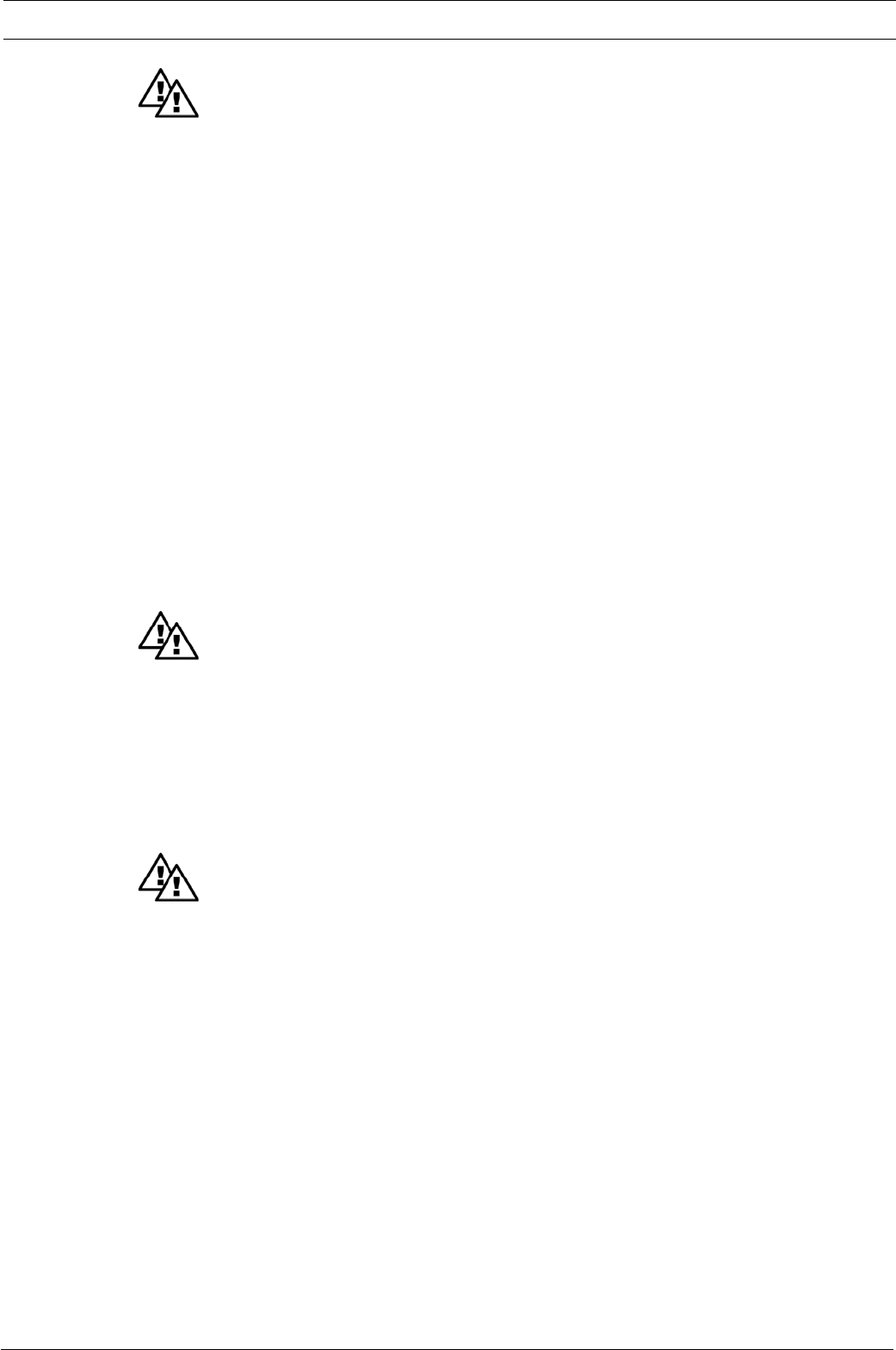
Fig. 1
2Product description S2Ba/S2Ca
WARNING
Use for intended purpose
• The pump is designed as a liquid medium metering pump; it serves the purpose of
metering liquid medium within the specified line system!
• In explosion-threatened workplaces in zone 1, device category II 2G of explosion group II
C the pump may not be operated without the corresponding rating plate (and the corre-
sponding EC conformity declaration) for pumps for explosion-threatened workplaces in
accordance with guideline 94/9/EC of the European guidelines.
•From July 1st, 2003 on, only pumps with the corresponding marking according to EC-Ex-
directive 94/9 may be used in industrial premises with potentially explosive atmospheres.
The explosion group, category and type of protection shown on the marking must
correspond to or exceed the conditions prevailing in the intended area of application.
•Operate the pump only within the conditions described in the technical data!
•General restrictions with regard to viscosity limits, chemical resistance and density must
be observed (refer to ProMinent® chemical resistance list (catalogue or homepage))!
•All other applications or conversion are prohibited!
•The pump is not designed to meter gaseous media as well as solids.
•For pumps without EX protection: The pump is not suitable for metering combustible
liquids!
•Pumps may never be operated in explosion-threatened workplaces without a corre-
sponding rating plate (and the corresponding EC conformity declaration) for pumps for
explosion-threatened workplaces.
•Only specifically trained and authorized personnel are permitted to operate the pump!
2.1 Identification of pump type
The identity code and serial number are given in addition to the standard technical specifications.
These two numbers must always be quoted when making any enquiries as they enable distinct
identification of the type of metering pump.
2.2 Design/Functional description
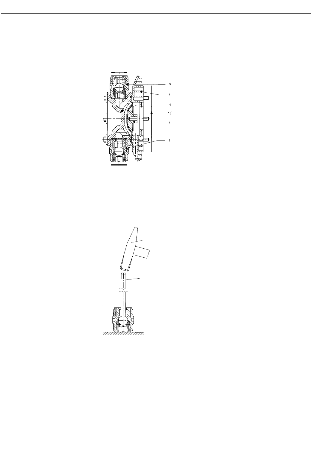
2.2.1 Functional description, drive
The ProMinent® Sigma/ 2 diaphragm-type metering pump is an oscillatory displacement pump
with the stroke length adjustable in steps of 0.5 %. It is driven by electric motor (1). The rotary
drive of the electric motor is stepped down by worm gear and transmitted via the eccentric roller
(3) to the push rod (4) connected to fork (8) and converted into oscillatory movement. Return
spring (5) presses the fork with push rod positively against the eccentric roller thus producing the
return stroke. The stroke is adjusted by means of stroke adjustment knob (6) and spindle (7) by
limiting the return stroke. Stroke movement is transmitted directly to the displacement diaphragm.
Interacting with the valves, this diaphragm produces the overpressure and vacuum in the liquid
end necessary for delivery. Flow is pulsating.
In the basic type, the electric motor is normally a 3-ph extended-range AC motor (refer to Section 3
for other options).
Page 16 ProMinent®
Dulcodes UV-Desinfektionsanlage
0180 360
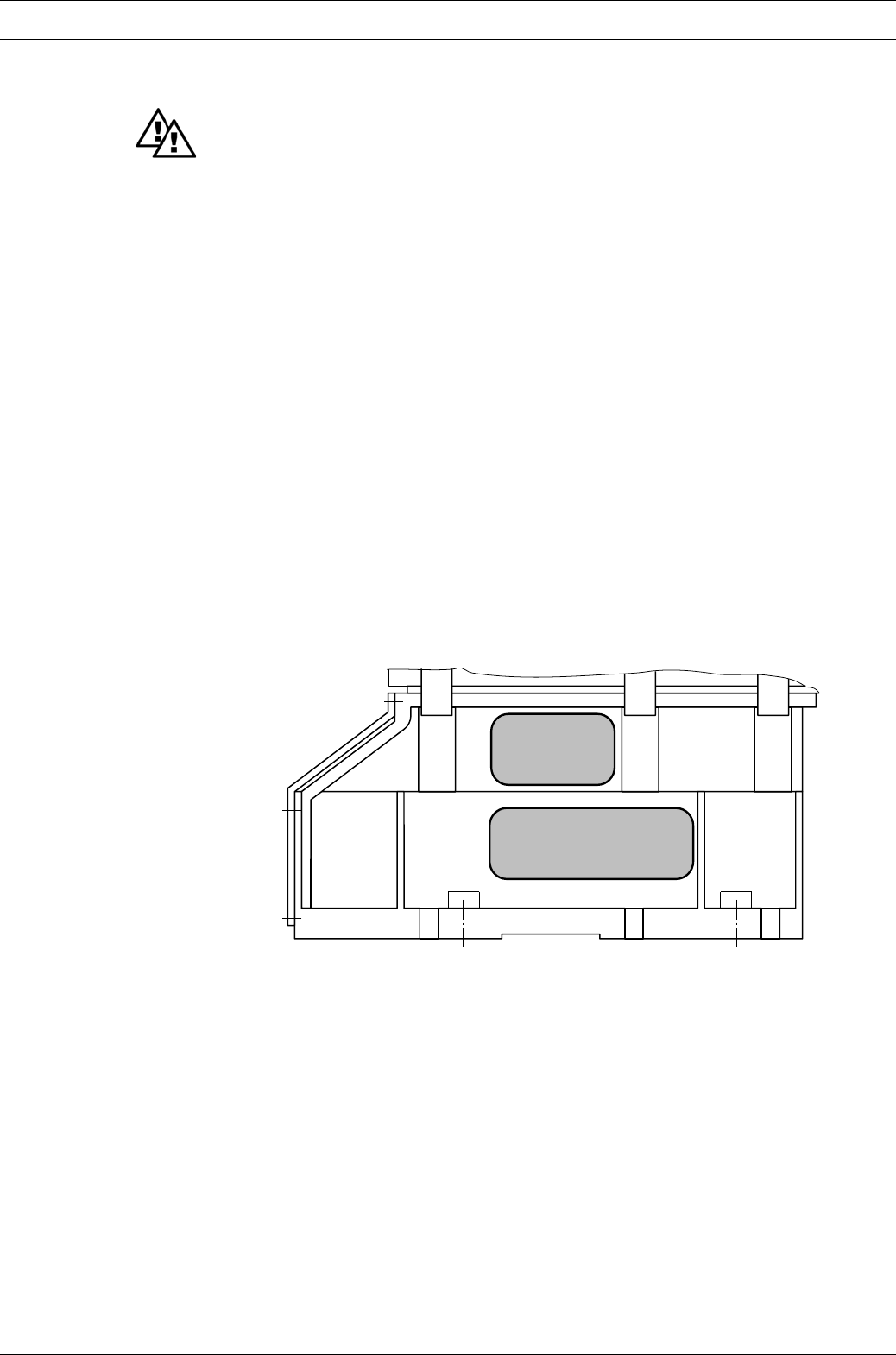
2.2.2 Stroke movement
Set stroke length dependent on the required delivery capacity.
Product description S2Ba/S2Ca
5
6
3
7
1
8
4
10
Fig. 2
61_01-101_00_25-01
NOTE
A large stroke length and low metering frequency should be selected for very viscous
media!
A shorter stroke length and high frequency should be selected to achieve good mixing
properties!
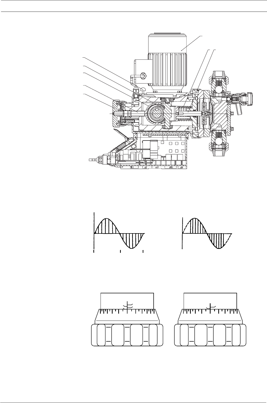
20 0
0
50
25
75
5
75%
05
0
25
10
30%
Fig. 4
75 % 30 %
Fig. 3
+ Delivery stroke
b) At reduced stroke length
– Intake stroke
a) Stroke progression
at max. stroke rate
and stroke length
Stroke speed
Angle reduced stroke length
Dulcodes UV-Desinfektionsanlage
Page 17
ProMinent®
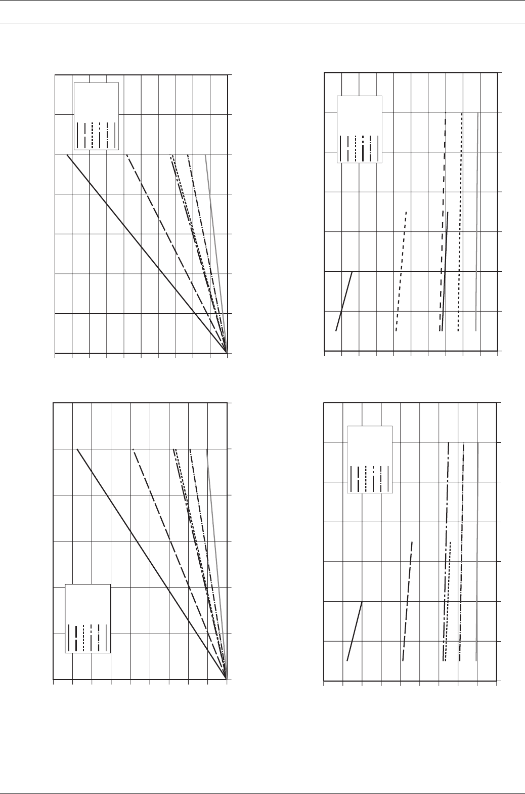
Metering capacity diagram S2Ba HM (50 Hz)
Stroke length in (%)
pressure in (bar)
Metering capacity diagram S2Ba HM (60 Hz)
2.2.3 Metering capacity diagram
Product description S2Ba/S2Ca
Metering capacity diagram S2Ba HM (60 Hz)
Stroke length in (%)
pressure in (bar)
Metering capacity diagram S2Ba HM (50 Hz)
0
50
100
150
200
250
300
350
400
450
020406080100 120
Q (l/h)
S2Ba HM 04350
S2Ba HM 07220
S2Ba HM 07120
S2Ba HM 12130
S2Ba HM 12090
S2Ba HM 12050
0
50
100
150
200
250
300
350
400
450
500
Q (l/h)
S2Ba HM 04350
S2Ba HM 07220
S2Ba HM 07120
S2Ba HM 12130
S2Ba HM 12090
S2Ba HM 12050
020406080100120
0
50
100
150
200
250
300
350
400
450
500
02468101214
Q (l/h)
S2Ba HM 04350
S2Ba HM 07220
S2Ba HM 07120
S2Ba HM 12130
S2Ba HM 12090
S2Ba HM 12050
0
50
100
150
200
250
300
350
400
450
02468101214
Q (l/h)
S2Ba HM 04350
S2Ba HM 07220
S2Ba HM 07120
S2Ba HM 12130
S2Ba HM 12090
S2Ba HM 12050
Page 18 ProMinent®
Dulcodes UV-Desinfektionsanlage
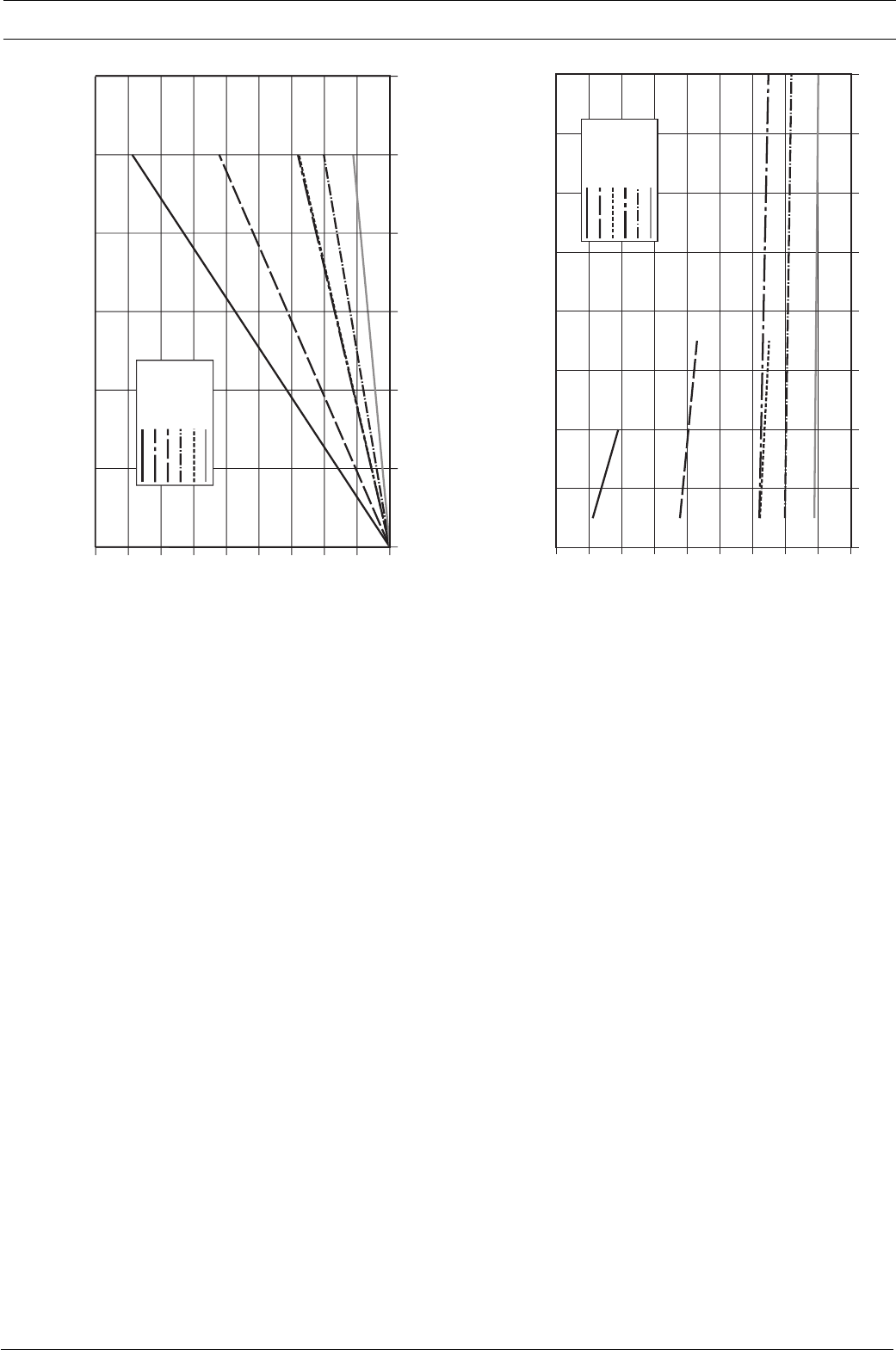
pressure in (bar)
Metering capacity diagram S2Ca HM
Stroke length in (%)
Metering capacity diagram S2Ca HM
Product description S2Ba/S2Ca
0
50
100
150
200
250
300
350
400
450
02 4 6 8101214
Q (l/h)
S2Ca HM 04350
S2Ca HM 07220
S2Ca HM 07120
S2Ca HM 12130
S2Ca HM 12090
S2Ca HM 12050
16
0
50
100
150
200
250
300
350
400
450
020406080100 120
Q (l/h)
S2Ca HM 04350
S2Ca HM 12130
S2Ca HM 07220
S2Ca HM 12090
S2Ca HM 07120
S2Ca HM 12050
Dulcodes UV-Desinfektionsanlage
Page 19
ProMinent®
Product description S2Ba/S2Ca
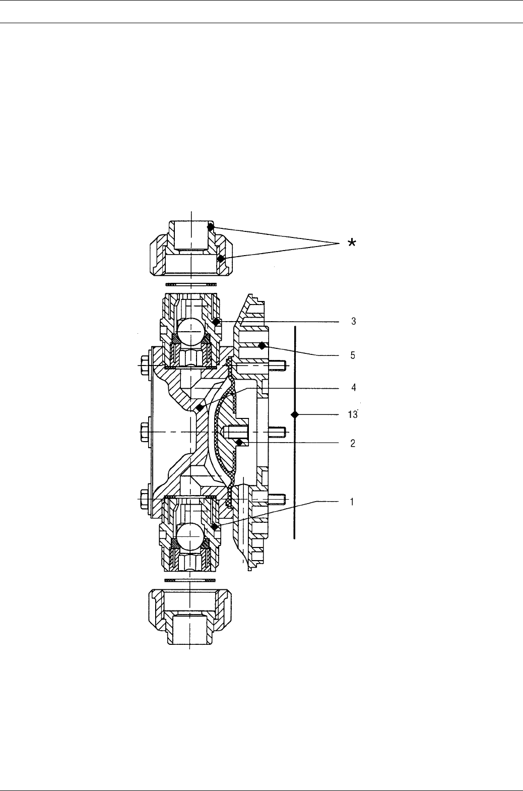
Fig. 5
3154-4
2.2.4 Functional description, delivery unit
The heart of the delivery unit is the DEVELOPAN® metering diaphragm (2). It hermetically seals
the delivery chamber of the liquid end (4) and produces a displacement in the liquid end. The end
disc (5) made of chemically resistant plastic together with safety diaphragm (13) separates the
drive housing from the delivery unit and protects the drive from corrosion in the event of the
diaphragm failing. Delivery is based on the interaction between intake valve (1) and head valve (3)
of the same design together with the diaphragm movement. The valve balls can be supported
with springs for metering viscous media.
The connection dimensions of valves and liquid ends of the same size but with different materials
are identical. These parts can be interchanged as required.
Materials and dimensions are specified in Section 3, Technical data.
Page 20 ProMinent®
Dulcodes UV-Desinfektionsanlage
Product description S2Ba/S2Ca
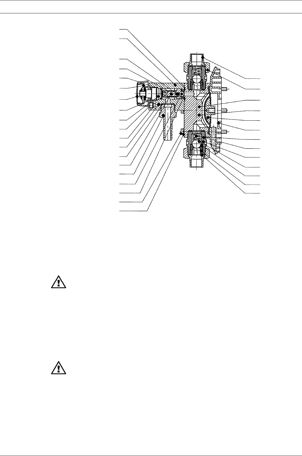
2.2.5 Integrated overflow valve with bleeder function
Task:
The task of the overflow valve is to protect the motor and gear unit against impermissible
overpressure caused by the metering pump.
This function is produced by a spring-loaded ball.
A pressure relief mechanism for the bleeder function is provided.
Design and functional description
(refer to Fig. No. 6 and 7)
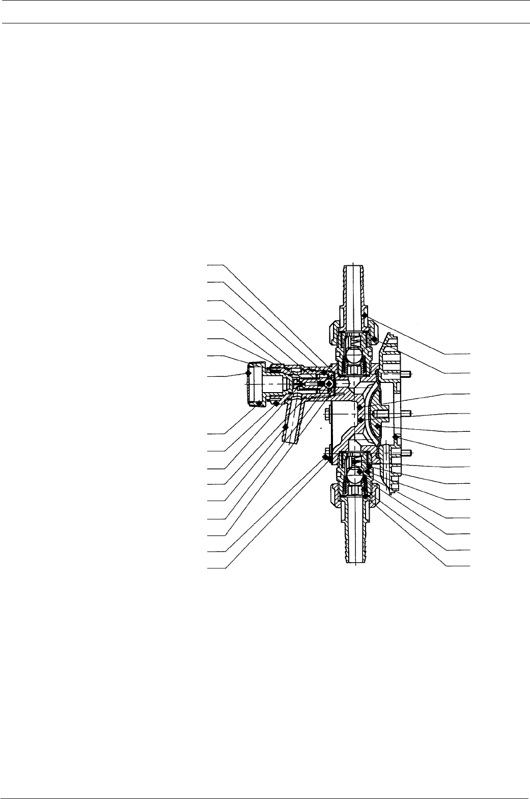
Initially, the overflow valve illustrated under item 102 operates as a simple directly controlled
safety valve. As soon as the pressure set with spring item 132 is exceeded, the effective pressure
raises ball item 130. The liquid then flows off into the tank via hose connection item 128.
Fig. 6
3160-4
Overflow valve Sigma/ 2 liquid end, 10 bar PVT Identcode Type: 12050, 12090, 12130
Overflow valve Sigma/ 2 liquid end, 7 bar PVT Identcode Type: 07120, 07220
Overflow valve Sigma/ 2 liquid end, 4 bar PVT Identcode Type: 04350
134
102
133
137
132
138
139*
131
202
203
126
125
127
136
128
130
111
112
100
110
114
115
118
200
201
117
101
113
116
Dulcodes UV-Desinfektionsanlage
Page 21
ProMinent®
Overflow valve Sigma/ 2 liquid end, 16 bar SST Identcode Type: 16050, 16090, 16130
Overflow valve Sigma/ 2 liquid end, 12 bar SST Identcode Type: 12050, 12090, 12130
Overflow valve Sigma/ 2 liquid end, 7 bar SST Identcode Type: 07120, 07220
Overflow valve Sigma/ 2 liquid end, 4 bar SST Identcode Type: 04350
Product description S2Ba/S2Ca
Fig. 7
3161-4
IMPORTANT
•Knob item 139 must be turned in clockwise direction as far as it will go towards ”close“.
•The bypass line must always be closed and must be routed back into the supply tank.
Connection via hose connection item 128.
•Minimal overflow can occur in the bypass line when the valve operates close to the
overpressure function.
The bleeder function is achieved by turning knob item 139 in counterclockwise direction as far as
it will go towards ”open“: Priming aid for starting up pump against pressure. The force of spring
item 132 relieves ball item 130 which is controlled by the lower spring force of bleeder spring
item 133.
IMPORTANT
Once the pump has primed, turn knob item 139 in clockwise direction as far as it will go
towards ”close“! The pump is now operational.
134
102
133
132
138
139*
131
202
203
126
125
127
136
128
130
111
112
100
110
114
115
118
200
201
117
101
113
116
137
141
140
129
Page 22 ProMinent®
Dulcodes UV-Desinfektionsanlage
Product description S2Ba/S2Ca
Technical data
Corresponding to the type of pump, overflow valves are available for pressure stages pnom 4, 7,
10, 12 and 16 bar with (1.05 ... 1.15) xpnom opening pressure.
Material in contact with metered medium
Material Liquid end Suction/ Seals Balls Springs Integrated
version discharge overload
connector valve
PVT PVDF PVDF PTFE Ceramic / glass* Hastelloy C PDFE/Viton®
SST Stainless steel Stainless steel PTFE Stainless steel Hastelloy C Stainless steel/
1.4571/1.4404 1.4581 1.4404 Viton®
*for 07120, 07220, 04350
Viton® is a registered trademark of DuPont Dow Elastomers.
Use for intended purpose/Use unintended purpose
Use for intended purpose
Protect the dosing pump against unacceptable high overpressure produced by the dosing pump.
Use the overflow value only in connection with liquid with a viscosity of up to max. 200 mPa s.
IMPORTANT
•The ceramic ball and ball seat of the overflow valve are wearing parts. Slight leakage can
occur at the safety valve after a prolonged period of operation. The ball and ball seat
should be replaced if leaks occur.
•The bypass line must always be connected and must be routed back into the supply tank.
Use for unintended purpose
To protect the system from impermissible overpressure.
The pump must not be operated without the bypass line connected.
The bypass line must not be connected in the intake line (the bleeder function will no longer be
guaranteed). The bypass line must be routed back into the supply tank.
WARNING
When carrying out maintenance work on the overcurrent valve, pay attention to the
tensioned state of the pressure spring item132! Wear safety goggles!
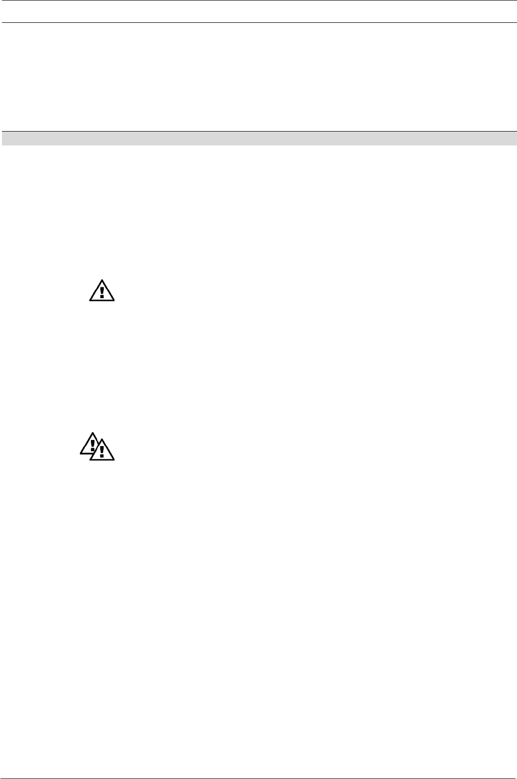
2.2.6 Diaphragm rupture sensor
Function:
Monitors the seals in the working diaphragm. This liquid end can continue to function for a short
period in emergency mode, i.e. full operating pressure, no leakage, even after diaphragm rupture.
Design and function description (see Fig. 8)
Liquid ends with diaphragm rupture sensors comprise a standard liquid end (item 100) a working
diaphragm (item 200) and an auxiliary diaphragm (item 148) The auxiliary diaphragm is positioned
between the back plate (item 201) and the interim plate (item 147) and forms a sealed
compartment together with the working membrane (item 200).
The leak tightness of the working diaphragm, Item 200, is monitored with a diaphragm failure
detector, Item 104, that triggers a contact signal in the event of diaphragm failure so that the
pump is stopped in the S2Ca and the diaphragm failure is indicated on a LCD.
Dulcodes UV-Desinfektionsanlage
Page 23
ProMinent®
FM 130
Identcode Type: 12050, 12090, 12130, 16050, 16090, 16130
FM 350
Identcode Type: 04350, 07120, 07220
Product description S2Ba/S2Ca
The liquid end can continue to operate in emergency mode, i.e. full operating pressure, no
leakage, even after diaphragm rupture, until the diaphragm has been replaced. We offer two
versions of the S3Ca with diaphragm rupture sensor:
•After a working diaphragm rupture, the pump stops and an ”error“ message/diaphragm sensor
signal is given.
•After a working diaphragm rupture, the pump will continue to run. An ”error“ message/
electrical signal is given.
A function plug is supplied which allows the pump to continue operating after a fault has
occurred (diaphragm rupture, failure of the diaphragm rupture sensor).
WARNING
•EX-pump only: Installations in potentially explosive atmospheres must be inspected by
an “accredited qualified” person. This applies in particular also for intrinsically safe
electrical circuits.
•EX-pump only: observe documents supplied with the sensor!
IMPORTANT
•In the case of the S2Ba, the customer should install a diaphragm rupture signal monitor
and/or ensure that the pump will stop after a diaphragm rupture.
• In the event of diaphragm failure, a contact signal is triggered as from 2 bar system
backpressure.
•Exact pump delivery can no longer be guaranteed after failure of the working diaphragm.
•The auxiliary diaphragm, Item 148, is a wearing part and must be replaced after failure
of the working diaphragm. The diaphragm rupture sensor lens, Item 156, should be
replaced after every diaphragm rupture.
Fig. 8
3162-4
111
112
118
203
204
200
100
116
110
101
117
113
114
115
103
147
148
149
158
160
104
150
201
159
156
157
155
161
162
163
Page 24 ProMinent®
Dulcodes UV-Desinfektionsanlage
Product description S2Ba/S2Ca
Material in contact with metered medium
Liquid end: Parts of diaphragm failure monitor in contact with medium
Lens, seals Intermediate disc Item 147,
Item 148, 156, 159 intermediate bush Item 150
PVDF PTFE PVDF
Stainless steel 1.4571 PTFE PVDF
Electrical data for the diaphragm breakage sensor
a) Switch contact
30 V DC/1 A or 125 V AC/0.6 A or 250 V AC/0.3 A
The diaphragm sensor is a N/C relay.
IMPORTANT
Before commencing operation, install the provided diaphragm breakage sensor together
with the gasket (Item159) and make the electrical connections.
NOTE
•For safety reasons it is advisable to connect a safe low voltage (e.g. EN 60335-1 (SELV)).
•The cable priority is arbitrary.
b) Namur sensor, intrinsically
5-25 V DC, Namur type and/or DIN 19234, zero volt design.
Rated voltage: 8 V DC (Ri ~ 1 kΩ)
Power consumption:
Active surface, uncovered > 3 mA
Active surface, covered < 2 mA
Rated switching distance: 1.5 mm
The monitor/feeder must be capable of evaluating current changes in order to indicate
diaphragm rupture!
WARNING
•EX-pump only: Installations in potentially explosive atmospheres must be inspected by
an “accredited qualified” person. This applies in particular also for intrinsically safe
electrical circuits.
•EX-pump only: observe documents supplied with the sensor!
IMPORTANT
•Before commencing operation, install the provided diaphragm breakage sensor together
with the gasket (Item159) and make the electrical connections.
• For pump without EX protection: For safety reasons it is advisable to connect a safe low
voltage (e.g. EN 60335-1 (SELV)).
Blue -
Brown +

Dulcodes UV-Desinfektionsanlage
Page 25
ProMinent®
3Technical data
3.1 Technical data Sigma/ 2
3.1.1 Capacity data
Technical data S2Ba at 50 Hz operation
Feed rate at Max. Suction Admissible Connection Shipping
maximum stroke lift priming suction / weight
back pressure rate pressure discharge
suction side side
Pump type Sigma/ bar l/h ml/stroke strokes/min. m Ws bar G - DN kg
12050 PVT 10 50 11.4 73 7 3 1"-15 15
12050 SST 12 48 11.4 73 7 3 1"-15 20
16050 SST 16 48 11.4 73 7 3 1"-15 20
12090 PVT 10 90 11.4 132 7 3 1"-15 15
12090 SST 12 86 11.4 132 7 3 1"-15 20
16090 SST 16 86 11.4 132 7 3 1"-15 20
12130 PVT 10 130 10.9 198 7 3 1"-15 15
12130 SST 12 125 10.9 198 7 3 1"-15 20
16130 SST 16 125 10.9 198 7 3 1"-15 20
07120 PVT 7 120 27.4 73 5 1 20* 16
07120 SST 7 120 27.4 73 5 1 20* 24
07220 PVT 7 220 27.7 132 5 1 20* 16
07220 SST 7 220 27.7 132 5 1 20* 24
04350 PVT 4 350 29.4 198 5 1 20* 16
04350 SST 4 350 29.4 198 5 1 20* 24
All performance data applies to water at 20 °C.
The suction lift applies when the suction line and liquid end are full and correctly installed.
*Sigma types 07120, 07220 and 04350, the valves used in the liquid end are DN 25 (G11/2). Since DN 20 is usually adequate for
this tubing (see Technical Data, connection-suction/discharge side) the connector parts to be ordered by Identcode (e.g.
washers) have already been reduced to DN 20, i.e. tubing and accessories can be DN 20.
Technical data
Technical data S2Ba at 60 Hz operation
Feed rate at Max. Suction Admissible Connection Shipping
maximum stroke lift priming suction / weight
back pressure rate pressure discharge
suction side side
Pump type Sigma/ bar psi I/h/gph strokes/min. m Ws bar G - DN kg
12050 PVT 10 145 60/ 15.9 87 7 3 1"-15 15
12050 SST 12 174 57/ 15.2 87 7 3 1"-15 20
16050 SST 16 232 57/ 15.2 87 7 3 1"-15 20
12090 PVT 10 145 108/ 28.5 156 7 3 1"-15 15
12090 SST 12 174 103/ 27 156 7 3 1"-15 20
16090 SST 16 232 103/ 27 156 7 3 1"-15 20
12130 PVT 10 145 156/ 41 232 7 3 1"-15 15
12130 SST 12 174 150/ 39.6 232 7 3 1"-15 20
16130 SST 16 232 150/ 39.6 232 7 3 1"-15 20
07120 PVT 7 100 144/ 38 87 5 1 20* 16
07120 SST 7 100 144/ 38 87 5 1 20* 24
07220 PVT 7 100 264/ 69.7 156 5 1 20* 16
07220 SST 7 100 264/ 69.7 156 5 1 20* 24
04350 PVT 4 58 420/ 111 232 5 1 20* 16
04350 SST 4 58 420/ 111 232 5 1 20* 24
All performance data applies to water at 20 °C.
The suction lift applies when the suction line and liquid end are full and correctly installed.
*Sigma types 07120, 07220 and 04350, the valves used in the liquid end are DN 25 (G11/2). Since DN 20 is usually adequate for
this tubing (see Technical Data, connection-suction/discharge side) the connector parts to be ordered by Identcode (e.g.
washers) have already been reduced to DN 20, i.e. tubing and accessories can be DN 20.
Page 26 ProMinent®
Dulcodes UV-Desinfektionsanlage
Technical data
Materials in contact with chemicals
Material Liquid end Suction/ Seals Balls Springs Integrated
version discharge overload valve
connector
PVT PVDF PVDF PTFE Ceramic / glass* Hastelloy C PDFE/Viton®
SST Stainless steel Stainless steel PTFE Stainless steel Hastelloy C Stainless steel/
1.4571/1.4404 1.4581 1.4404 Viton®
* for 07120, 07220 and 04350
Temperature specifications
Permissible storage temperature: –10 to +50 °C
Permissible ambient temperature: –10 to +40 °C
Temperature compatibility (medium temperature) of materials
Material: Long-term at max. Short-term, max. 15 min.
backpressure: at max. 2 bar
PVT 65 °C 100 °C
SST 90 °C 120 °C
The specified temperatures (see above) can be exceeded temporarily, e.g. for sterilisation or
flushing with hot water.
Accuracy
Under constant conditions and in minimum stroke length of 30 % corresponding to following
notes, the reproducibility of the metered quantity is better than ±2 %.
All specifications refer to metered quantities with water at 20 °C and correct installation of the
metering pump.
Technical data S2Ca
Feed rate at Max. Suction Admissible Connection Shipping
maximum stroke lift priming suction / weight
back pressure rate pressure discharge
suction side side
Pump type Sigma/ bar l/h ml/stroke strokes/min. m Ws bar R - DN kg
12050 PVT 10 145 60/ 16 90 7 2 1"-15 17
12050 SST 12 174 60/ 16 90 7 2 1"-15 22
16050 SST 16 232 60/ 16 90 7 2 1"-15 22
12090 PVT 10 145 95/ 25 160 7 2 1"-15 17
12090 SST 12 174 95/ 25 160 7 2 1"-15 22
16090 SST 16 232 95/ 25 160 7 2 1"-15 22
12130 PVT 10 145 136/ 36 200 7 2 1"-15 17
12130 SST 12 174 136/ 36 200 7 2 1"-15 22
16130 SST 16 232 136/ 36 200 7 2 1"-15 22
07120 PVT 7 100 148/ 39 90 5 1 11/2 - 20* 18
07120 SST 7 100 148/ 39 90 5 1 11/2 - 20* 26
07220 PVT 7 100 232/ 61 160 5 1 11/2 - 20* 18
07220 SST 7 100 232/ 61 160 5 1 11/2 - 20* 26
04350 PVT 4 58 350/ 93 200 5 1 11/2 - 20* 18
04350 SST 4 58 350/ 93 200 5 1 11/2 - 20* 26
All performance data applies to water at 20 °C.
The suction lift applies when the suction line and liquid end are full and correctly installed.
*Sigma types 07120, 07220 and 04350, the valves used in the liquid end are DN 25 (G11/2). Since DN 20 is usually adequate for
this tubing (see Technical Data, connection-suction/discharge side) the connector parts to be ordered by Identcode (e.g.
washers) have already been reduced to DN 20, i.e. tubing and accessories can be DN 20.
Dulcodes UV-Desinfektionsanlage
Page 27
ProMinent®
PVDF
PP/PVC/PTFE
SS
Connection
variations
3.1.3 Dimension sheet Sigma/ 2 with stroke adjustment motor
Anschluss-
varianten
Fig. 10
61_01-101_00_39-73_2_HM
Fig. 9
61_01-101_00_32-73
3.1.2 Dimensions Sigma/ 2 (mm)
* Dimensions for S2Ba
Technical data
18
100
186
78
218
Ø165
ØG
136
120
A
B
F
E/El
222
D/Dl 120
28
185/170*
Ø 6.5 +7
26.5
456/441*
C
79.5
Model Connector A B C D D1** E E1** F Q G
FM 130 PVT DN 15 265/250* 160 G 1 A 104 124 326/329* 346/349* 82 101
FM 130 SST DN 15 265/250* 160 G 1 A 104 124 326/329* 346/349* 82 101
FM 350 PVT DN 25 304/289* 237 G 1 1/2 A 115 135 337/340* 357/360* 84 148
FM 350 SST DN 25 304/289* 237 G 1 1/2 A 115 135 337/340* 357/360* 84 148
FM 130 = Identcode type 16050,16090,16130 FM 350 = Identcode type 04350,07120,07220
*Dimensions for S2Ba
** Dimensions with diaphragm rupture sensor
Page 28 ProMinent®
Dulcodes UV-Desinfektionsanlage
Technical data
230 V ± 10 % 50/60 Hz 11.7 W
115 V ± 10 % 60 Hz 11.7 W
230 V ± 10 % 50/60 Hz 6.5 W
115 V ± 10 % 60 Hz 6.5 W
3.1.4 Motor data
Electrical Data
Motors: Identcode characteristic
3 ph IP 55 230 V/400 V 50 Hz 0.25 kW 1.62/0.94 A S
3 ph IP 55 230 V/400 V 60 Hz 0.25 kW 1.42/0.82 A S
1 ph AC 230 V 50/60 Hz 0.18 kW 1.7/1.5 A M
1 ph AC 115 V 60 Hz 0.18 kW 3.3 A N
3 ph EXe or EXde 230 V/400 V 50 Hz 0.18 kW 1.1/0.7 A L
3 ph EXe or EXde 230 V/400 V 60 Hz 0.18 kW 1.1/0.6 A P
3 ph IP 55 230 V/400 V 50/60 Hz 0.37 kW ...... R Version with external fan
1 PH 230 v; 50/60 Hz and PTC
1 ph IP 55 230 V 50/60 Hz 0.37 kW ..... V Three phase motor with integrated
speed changer, (see chapter 11)
For more details you can request the motor specification sheets. Custom motors and/or custom
motor flanges are available on request.
WARNING
•EX-pump only: Drive motors must be secured by an appropriate motor protection switch.
A motor protection approved for this application must be used for Ex“e”-motors.
(Protection against heating due to overload)
•EX-pump only: motors in EX-areas must be installed and checked by persons with
“recognised skills”!
•EX-pump only: observe the operating manual supplied with the EX motor!
Fuse data
IMPORTANT
•The motors are not fuse-protected. Fit a motor circuit breaker!
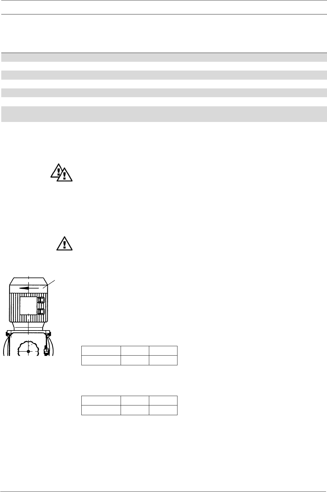
•
When connecting the motor, make sure that it rotates in the correct direction (see Fig. 11
).
Protection against accidental contact and moisture (IP)
Motor: IP 55 DIN EN 60034-5 (in accordance with DIN VDE 0470 Part 1, corresponds to
EN 60529 and IEC 529).
External fan
Notes on the speed-controlled motor with separate fan and temperature monitoring may be
found in the “General Operating Instructions ProMinent® Motor-Driven Metering Pumps and
Hydraulic Accessories”.
3.1.5 Stroke actuator drive mechanism
Cf. “Appendix” for terminal connection diagram.
3.1.6 Stroke adjuster drive mechanism
Cf. “Appendix” for terminal connection diagram.
3.1.7 Electrical data, stroke sensor “Sigma”
a) Reed contact (Identcode characteristic “Stroke sensor”: 1)
Pin 1 (white) = 4.5 V to 24 V, max. 10 mA
Pin 2 (brown) = OUT, open collector, 24 V, 20 mA
Pin 3 (green) = GND
Pulse width (low) ≥4 ms (depending on gearbox and power frequency)
Fig. 11
direction
of rotation

Dulcodes UV-Desinfektionsanlage
Page 29
ProMinent®
Technical data
Blue -
Brown +
b) Namur sensor, intrinsically (Identcode characteristic “Stroke sensor”: 3)
WARNING
•EX-pump only: intrinsically safe installations must be installed and checked by persons
with “recognised skills”!
•EX-pump only: observe documents supplied with the sensor!
5-25 V DC, Namur type and/or DIN 19234, zero volt design.
Rated voltage: 8 V DC (Ri ~ 1 kΩ)
Power consumption:
Active surface, uncovered > 3 mA
Active surface, covered < 1 mA
Rated switching distance: 1.5 mm
The monitor/feeder must be capable of evaluating current changes in order to indicate
diaphragm rupture!
3.1.8 Electrical data, pacing relay “Sigma”
Relay input
(power supply for the relay board)
Input voltage Mains frequency Power consumption
200/230 V AC (180-254 V) 50/60 Hz 10 mA (230 V/50 Hz)
100/115 V AC (90-134 V) 50/60 Hz 15 mA (115 V/60 Hz)
24 V DC (20-28 V) - 10 mA at 24 V DC
Relay output
Voltage, max. 24 V DC
Current, max. 100 mA
Hook up duration 100 ms
Standard adjustable
The contacts are zero volt.
3.1.9 Sound intensity level
The sound intensity level is < 70 dB (A)
at maximum stroke, maximum stroking rate, maximum back pressure (water) in accordance with
DIN EN 12639 (noise measurement in fluid pumps)
Page 30 ProMinent®
Dulcodes UV-Desinfektionsanlage
4Start-up/Maintenance
WARNING
•For all metering pumps for metering inflammable media applies: Starting up and
emptying only supervised by a competent person.
IMPORTANT
Observe the safety notes provided in Section 1.
4.1 Start-up
All general guidelines in the accompanying ”General operating instructions ProMinent®
motordriven metering pumps and hydraulic accessories” apply.
Diaphragm pumps with mechanically actuated diaphragm: no additional measures necessary,
however, version with diaphragm rupture indicator, version Ex“i”*, must be used on principle.
For all metering pumps for metering inflammable media applies: starting up and emptying only
supervised by a competent person.
Inflammable media may only be lifted with stainless steel liquid ends. - For exceptional cases,
where this is not possible, also PTFE with carbon may be used, our versions TT_ are made of
conductive plastics. In this case, special attention must be paid by the user due to the lower
mechanical stability.
4.2 Maintenance
WARNING
•EX-pump only: Wear parts (diaphragms, bearings etc.) of metering pumps used in
potentially explosive atmospheres must be replaced after having completed 90% of their
nominal product life.
•The lubricant supply must be regularly checked for lubricated pumps, for instance by
checking the fill level, visual inspection for leakages etc.
•EX-pump only: check that the pressure relief valve downstream from the pump is
functioning correctly!
The pressure relief valve must prevent the gearbox from being overloaded and
overheating in explosion-threatened workplaces!
•The proper general function, in particular of the drive, must be safeguarded by regular
inspections (leakages, noises, temperatures, possible discoloration due to excess
temperatures....).
•Use original spare parts should exchange become necessary!
• EX-pump only: When cleaning plastic parts, attention must be paid to not generating any
electrostatic charge by rubbing excessively. - see danger sign.
• EX-pump only: metering pumps and their peripheral equipment must be serviced by
specially trained or authorised personnel!
IMPORTANT
After loosening the liquid end screws (e.g. to change the valves or diaphragm), the screws
must be retightened clockwise to the specified tightening torque.
What requires maintenance?
•Secure fit of liquid end screws.
•Secure fit of metering lines (intake and delivery sides).
•Secure fit of head valve and intake valve.
•Leakage hole at end disc for moisture (indicates possible diaphragm failure).
•Operate pump continuously for a short period of time in order to check whether it delivers
correctly.
Start-up/Maintenance
Dulcodes UV-Desinfektionsanlage
Page 31
ProMinent®
Maintenance intervals
General recommendation for maintenance intervals - every 3 months.
Shorter intervals are recommended if operated under load conditions (e.g. continuous operation).
The gear oil should be changed after approx. 5000 duty hours.
Gear oil ISO viscosity class VG 460, e.g. Mobil Gear 634,
ProMinent Order No. 555325 (Amount of oil approx. 0.5 l).
The metering diaphragm is a wearing part whose service life is dependent on following parameters:
•System backpressure.
•Operating temperature.
•Properties of medium to be metered.
The service life of the diaphragm is restricted in the case of abrasive media. In such cases, it is
recommended to check the diaphragm more frequently and to install a diaphragm failure monitor.
4.3 Replacement of wearing parts
Replacing diaphragm (see exploded diagrams in appendix!)
WARNING
• EX-pump only: metering pumps and their peripheral equipment must be serviced by
specially trained or authorised personnel!
•Always use original spare parts.
IMPORTANT
Flush liquid end first in the case of hazardous media. For this purpose, force water or a
suitable flushing agent through the intake connection of the liquid end with a wash bottle.
왘Set stroke length to zero with the pump running. Switch off pump.
왘Release the six screws holding the liquid end, detach liquid end together with screws.
왘Release diaphragm from the push rod by jolting in counterclockwise direction and unscrew.
왘Screw on new diaphragm until it is firmly seated on the push rod. Mount the dosing head with
screws such that the suction connection lies at the bottom (observe the flow through direction /
arrow marks on the valves). Switch on pump. Set stroke length to 100% and turn in screws
then tighten crosswise to 7.5 ± 0.5 Nm. Check pump for leaks at max. pressure.
Start-up/Maintenance
Page 32 ProMinent®
Dulcodes UV-Desinfektionsanlage
NOTE
The tightening torque of the liquid end screws should be rechecked after 24 hours of
operation.
The tightening torques of the liquid end screws should be checked every 3 months for the
PVT material version.
Start-up/Maintenance
Fig. 13
approx. 300 g
Brass rod 9 mm diam. x approx. 200 mm
Fig. 12
GUIDELINE ON VALVE INSTALLATION
In the case of suction problems during installation, place the valves on a firm surface and tap the
PTFE ball seat disk lightly with a brass rod and a hammer weighing about 300 g. Let the valves
operate in the wet state.
NOTE
•If suction problems with the pump or leakage at the overcurrent valve are encountered,
first clean the ball and the ball seat disc.
•For media containing particles larger than 0.3 mm it is absolutely essential to install a
filter in the suction line.

Dulcodes UV-Desinfektionsanlage
Page 33
ProMinent®
Features of the S2Ca metering pumps
5Features of the S2Ca metering pumps
5.1 Function description, motors
The pump has an integrated electronic overload cut-out in all versions. This responds as soon as
the maximum admissible power consumption is reached and stops the motor.
왘If the motor stops due to a system overload the electronic controller detects the fault and
transmits a message which is displayed on the display panel and at the pump.
왘The fault signal can be cancelled by pressing the ”P“ key, altering the level for a brief period at
the pause input (switch function) or by reconnecting the pump to the mains.
IMPORTANT
If the motor has been switched off via the electronic overload cut-out, check that the pump
is not continuously overloaded.
NOTE
•The motor is supplied pre-wired.
• The performance data in 3.1.1 are measured with the S2Ba (base model with 3-phase
motor). If the S2Ba has been fitted with a 1-phase motor there may be up to 5 % speed
reduction due to the different motor characteristic curve, i.e. corresponding 5 % reduced
feed rate.
•
The controller changes over to digital stroking mode at low stroke frequencies! This takes
place at stroke frequencies below 1/3 of the maximum stroke frequency. This function is
designed to ensure sufficient cooling of the motor and low stroke frequencies.
Type: 100 – 230 V ± 10 %, 50/60 Hz
at 100 V at 230 V
nominal output 250 W 250 W
nominal current 3.2 A 2.0 A
peak current (in operation)* 10 A 5.5 A
making peak current 12 A 24 A
fuse, internal** 4.0 AT (1.5kA) 4.0 AT (1.5kA)
*internal switching
** Only genuine ProMinent fuses, item no. 732414, may be used!
5.2 Function description, controller
Operating modes Operating modes are selected using the MODE menu (depending upon identity code, some
operating modes may be absent).
“Analogue” operating mode: (Identity code, control variant: analogue)
The stroke rate is controlled via an analogue electrical signal via the “external control” terminal.
Signal processing is pre-selected at the controller.
“Manual” operating mode:
The stroke rate is controlled manually via the controller.
“Contact” operating mode:
This operating mode offers the opportunity to make fine adjustments with small increase/
decrease factors. Dosing can be activated by a pulse via the “external control” terminal or by a
semiconductor element. With the “pulse control” option it is possible to pre-set a feed quantity
(batch) or number of strokes (factor 0.01 to 99.99) via the control unit.
“Batch” operating function:
This operating mode offers the option of working with larger transfer factors (up to 65535).
Metering can be triggered by pressing the P key or a pulse from the “external control” terminal
via a contact or semiconductor element. A batching quantity or number of strokes can be pre-
selected via the control unit.

Page 34 ProMinent®
Dulcodes UV-Desinfektionsanlage
Features of the S2Ca metering pumps
“PROFIBUS®” mode: (Identity code, control variant: PROFIBUS®)
This operating mode provides the option of controlling the pump via the PROFIBUS® (see
“Supplementary instructions for ProMinent® gamma/ L and ProMinent® Sigma versions with
“PROFIBUS®”).
Functions The following functions can be selected using the SET menu:
“Calibrate” function (Identcode, stroke length adjustment: manual + calibration):
The S3Ca can be operated in all operating modes including in calibrating mode. The
corresponding continuous displays can show the actual feed quantity or the feed rate.
Calibration is maintained within the stroke frequency range 0-180 strokes/ min. Calibration is
also maintained when a stroke frequency is altered up to ±10 % scale divisions.
“Auxiliary frequency” function:
It is possible to set a stroke rate in the SET menu, which may be activated via the “external
control” terminal. This auxiliary frequency overrides all other pre-set stroke rate frequencies.
“Flow” function:
Stops the S2Ca when the flow is insufficient. In the SET menu, the number of failed strokes is
entered after which the pump will be turned off.
The following functions are available as standard:
“Float switch” function:
Information on the liquid level in the feed chemical container is transmitted to the S2Ca. This
option requires the installation of a 2-stage float switch. This is connected to the “float switch”
terminal.
“Pause” function:
The S2Ca can be stopped by remote control via the “external control” terminal. The “pause”
function operates only via the “external control” terminal.
The following functions are activated by keystrokes:
“Stop” function:
The S2Ca can be stopped by pressing the STOP/START key without disconnecting from the
mains power supply.
“Prime” function:
Priming (short term feed at maximum frequency) is activated by pressing both arrow keys at
the same time (in “Stroke rate” permanent display).
Optional relay The S2Ca has two connection options (not in PROFIBUS® version).
Optional “fault-indicating relay” or “power relay”:
In the event of fault signals, warning signals or float switch activation signals, connects an
electrical circuit to trigger alarm sirens etc. The relay is retrofitted via an aperture in the power
end.
“Fault indicating and pacing relay” option:
In addition to the fault indicating relay the pacing relay can make a contact with every stroke.
The relay is retrofitted via an aperture in the power end.
Function and error
indicators The operating and error status is shown via the three LEDs and the “error” indicator on the
LCD (see also section 9):
LCD indicator If a fault occurs “error” will appear along with an additional fault warning.
LED indicator Operating indicator (green)
This indicator is lit as long as the S2Ca is operating correctly. It goes out briefly with every
stroke.
Warning indicator (yellow)
This warning light appears if the S2Ca electronics detect a situation that could lead to a fault,
e.g. “liquid levels low 1st stage”.
Error indicator (red)
This warning light appears if a fault occurs, e.g. “liquid levels low 2nd stage”.
Dulcodes UV-Desinfektionsanlage
Page 35
ProMinent®
Features of the S2Ca metering pumps
Hierarchy of operating modes, functions and fault statuses
The different operating modes, functions and fault statuses each have a differing effect on
whether and how the S2Ca functions. These effects are given below:
1. Prime
2. Fault, stop, pause
3. Auxiliary frequency
4. Manual, analogue, contact, batch
i.e.
1. “Prime” can be activated in “Stroke rate” permanent display in any pump status
(as long as it is operable)
2. “Fault”, “stop” and “pause” stop all system parts up to “prime”.
3.
The stroke rate of the “auxiliary frequency” always overrides the stroke rates of the operating
modes listed in point 4.
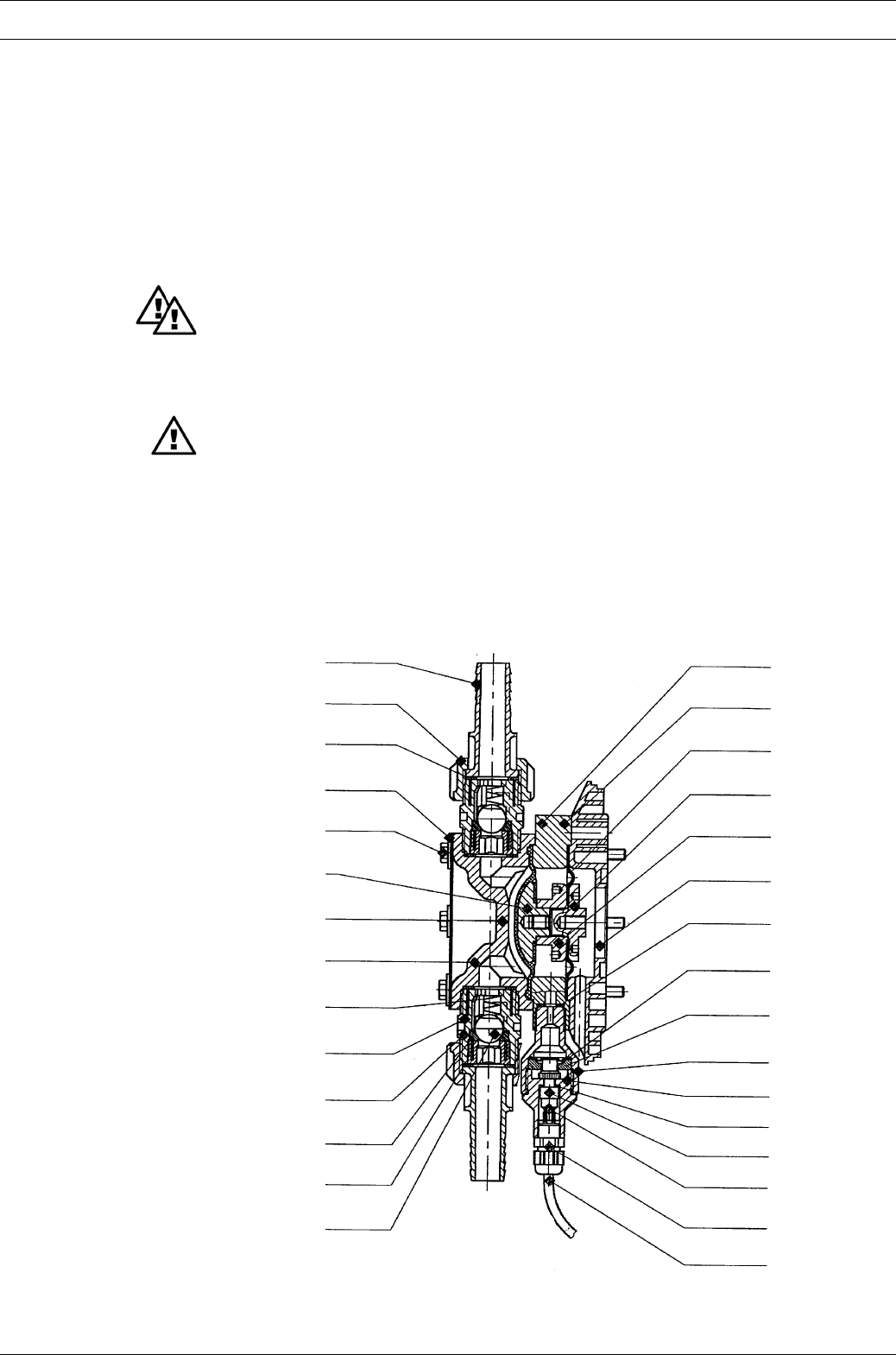
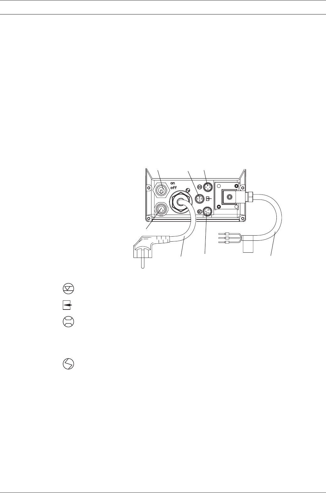
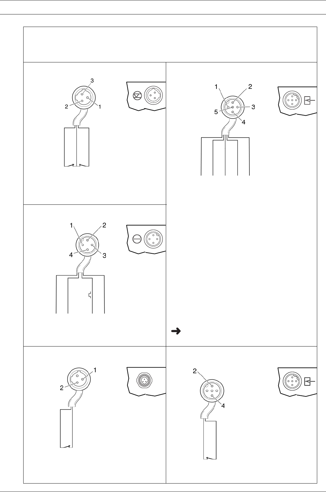
5.3 Sockets, symbols and wiring diagram
(1) Socket for two-stage float switch with advance warning and de-activate function (with
function plug*, not illustrated)
(2) External socket for contact or analogue controller with zero volts deactivation via pause
function (with function plug* - not illustrated)
(3) Metering monitor socket for connection of ProMinent® metering monitor
(4) Mains switch (1-pin)
(5) Relay cable (fault indicating or pacing relay)
(6) Socket for diaphragm rupture sensor
(7) Mains lead with plug
*Must be plugged in unless cable attached.
Fig. 14
4
1
75
23
6
Page 36 ProMinent®
Dulcodes UV-Desinfektionsanlage
Features of the S2Ca metering pumps
2
1
4
green/NC
white/NO
brown/C
pacing relay
fault indicating relay
yellow/NO
white/NO
green/NC
brown/C
1
4
3
2
2
3
1
4
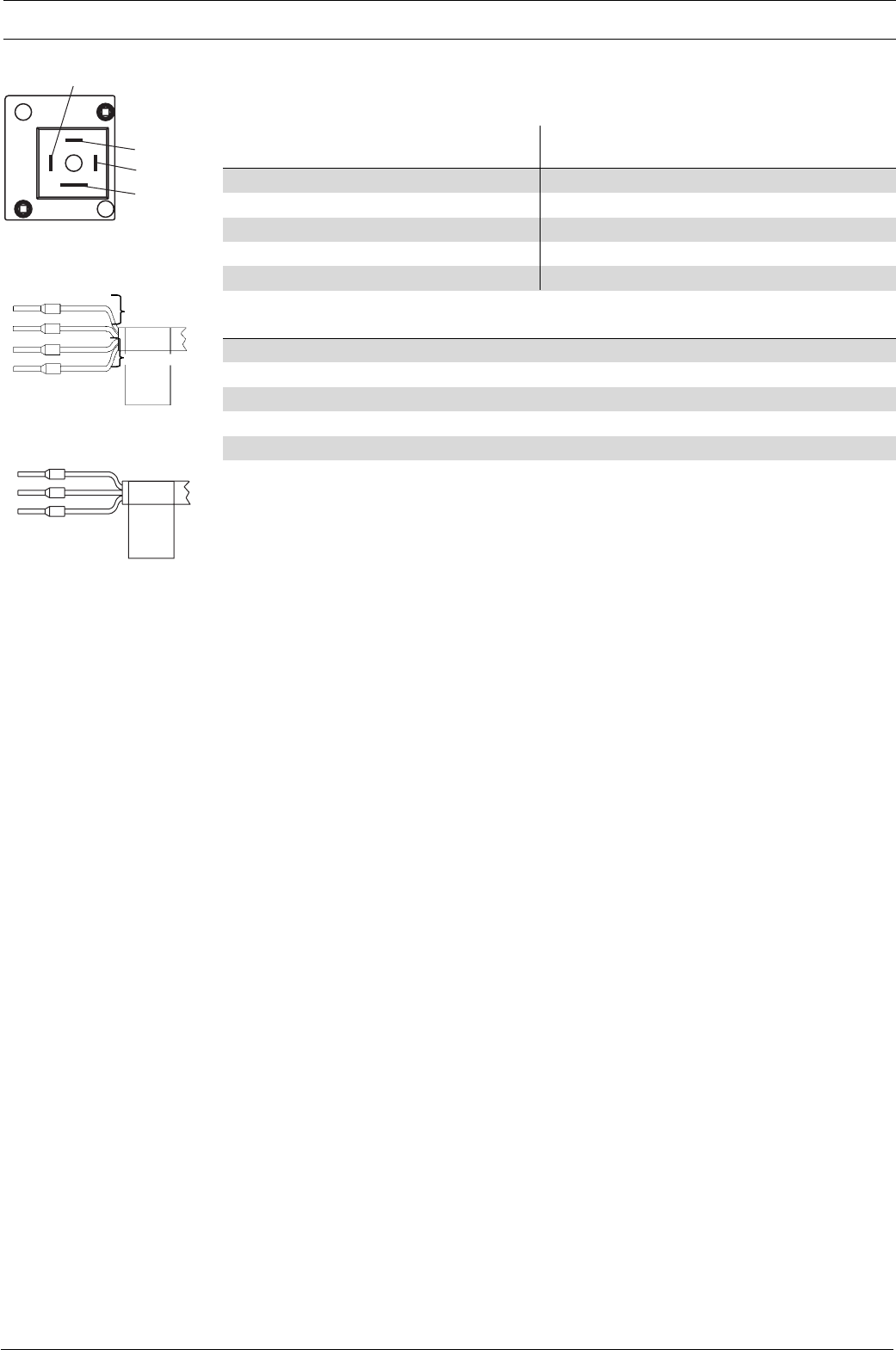
Technical data, relay (control version)
Pump type S2Ca
Relay Fault-indicating relay Fault-indicating relay + pulse generator
Relay type Fault-indicating relay pulse generator Fault-indicating relay
Voltage, max: 250 V 50/60 Hz 24 V DC 24 V 50/60 Hz
Current, max. 2 A (ohmic) 100 mA 100 mA
Hook up duration 100 ms
Behaviour see Identcode see Identcode see Identcode
Service life > 200 000 cycles* > 50 x 106 (10 V 10 mA) > 200 000 cycles
Relay type Power relay
Voltage, max. 250 V (50/60 Hz)
Current, max. 16 A (ohmic)
Hook up duration
Behaviour see Identcode
Service life > 30 000 cycles*
* in the case of nominal load
The contacts are zero volt.
N/C fault indicating relay - the relay closes immediately after the power is switched on and opens
in the event of a fault.
N/O fault indicating relay, the relay closes in the event of a fault.
Use suitable interference suppression (e.g. RC glands) when connecting inductive loads.
Dulcodes UV-Desinfektionsanlage
Page 37
ProMinent®
Wiring diagram
View of cable connectors from front
Float switch cable
for Universal signal cable (5-core)
for
Metering monitor cable
for
Diaphragm rupture cable
for
External/contact cable (2 core)
for
Contact open -> alarm
-> pump stops with controller type 0 Contact closed -> metering stroke
Blue and black open
-> alarm signal
Brown and black open
-> alarm signal + pump stops Pause function:
brown and black closed
-> pump metering
brown and black open
-> alarm + pump stopped
External/contact:
white and black closed
-> start contact for pump
(note pause function:
brown and black closed?)
Analogue:
blue, black
-> analogue output 0/4-20 mA
(note pause function:
brown and black closed?)
Auxiliary frequency:
grey and black closed
-> pump metering at pre-set stroking rate
Circuit examples see p. 40
Features of the S2Ca metering pumps
2 blue/alarm
1 black GND
3 brown pause
1 brown / 5 V
2 white/cod
3 blue
4 black/ GND
1 brown / pause
2 white/cod
3 blue / analogue
4 black/ GND
5 grey/auxiliary
2 brown
4 white
2 blue/alarm
1 black/GND

Page 38 ProMinent®
Dulcodes UV-Desinfektionsanlage
Technical data, external contact
Semi-conductor switch elements (e.g. transistors in open-collector circuits) or contactors (relays)
with a residual voltage of -0.7 V can be used as input switch elements.
Controller type 0 (see identity code)
Pin 1 = Pause input (activating function)
Voltage at open contacts: approx. 5 V
Input resistance: 10 kΩ
Controller: – zero volts contact (approx. 0.5 mA)
– semi-conductor (residual voltage: < 0.7 V)
Pin 2 = Contact input
Voltage at open contacts: approx. 5 V
Input resistance: 10 kΩ
Controller: – zero volts contact (approx. 0.5 mA)
– semi-conductor (residual voltage: < 0.7 V)
Min. contact duration: 20 ms
Max. pulse frequency: 25 pulses/s
Pin 3 = unused
Pin 4 = GND
Pin 5 = Auxiliary input
Voltage at open contacts: approx. 5 V
Input resistance: 10 kΩ
Controller: – zero volts contact (approx. 0.5 mA)
– semi-conductor (residual voltage: < 0.7 V)
Controller type 1 (see identity code)
Pin 1 = Pause input (activating function)
Voltage at open contacts: approx. 5 V
Input resistance: 10 kΩ
Controller: – zero volts contact (approx. 0.5 mA)
– semi-conductor (residual voltage: < 0.7 V)
Pin 2 = Contact input (not active during analogue operation)
Voltage at open contacts: approx. 5 V
Input resistance: 10 kΩ
Controller: – zero volts contact (approx. 0.5 mA)
– semi-conductor (residual voltage: < 0.7 V)
Min. contact duration: 20 ms
Max. pulse frequency: 25 pulses/s
Pin 3 = Identical to input*
Input load: approx. 120 Ω
Pin 4 = GND
Pin 5 = Auxiliary input
Voltage at open contacts: approx. 5 V
Input resistance: 10 kΩ
Controller: – zero volts contact (approx. 0.5 mA)
– semi-conductor (residual voltage: < 0.7 V)
* The metering pump makes its first metering stroke at approx. 0.4 mA (4.4 mA) and starts
continuous operation at approx. 19.2 mA.
Features of the S2Ca metering pumps
Dulcodes UV-Desinfektionsanlage
Page 39
ProMinent®
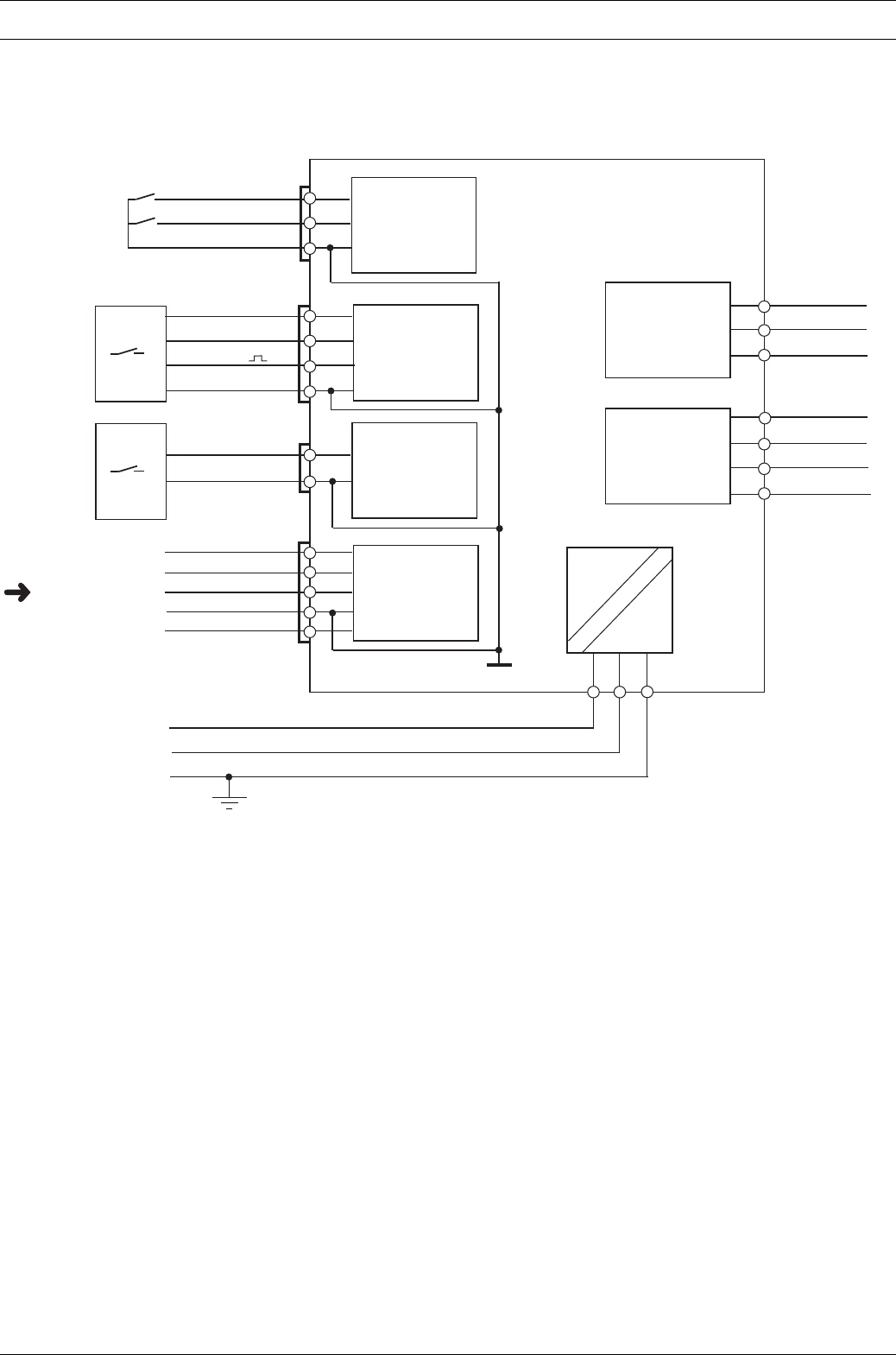
Block circuit diagram S2Ca
Features of the S2Ca metering pumps
Inputs
Pump, Inside
Outputs
GND
External
activation
Diaphragm
rupture
sensor
Metering
monitor
Level
monitor
Fault
indicating
relay
warning
Mains
Circuit
examples
overleaf
Metering
monitor
Flow control
Diaphragm
rupture
sensor
3 white/NO (pacing)
Fault
indicating
and
pacing relay
VDE cable:
Empty signal,
2 brown/C (pacing)
1 white /NO
4 brown/C
1 yellow/NO (fault)
4 green/C (fault)
2 green/NC
3 brown/pause
2 blue/alarm
1 black/GND
1 brown/5 V
2 white/cod
4 black/GND
3 blue
2 blue/alarm
1 black/GND
VDE cable:
1 brown/pause
2 white/contact
4 black/GND
3 blue/analogue
5 grey/auxiliary
Page 40 ProMinent®
Dulcodes UV-Desinfektionsanlage
Features of the S2Ca metering pumps
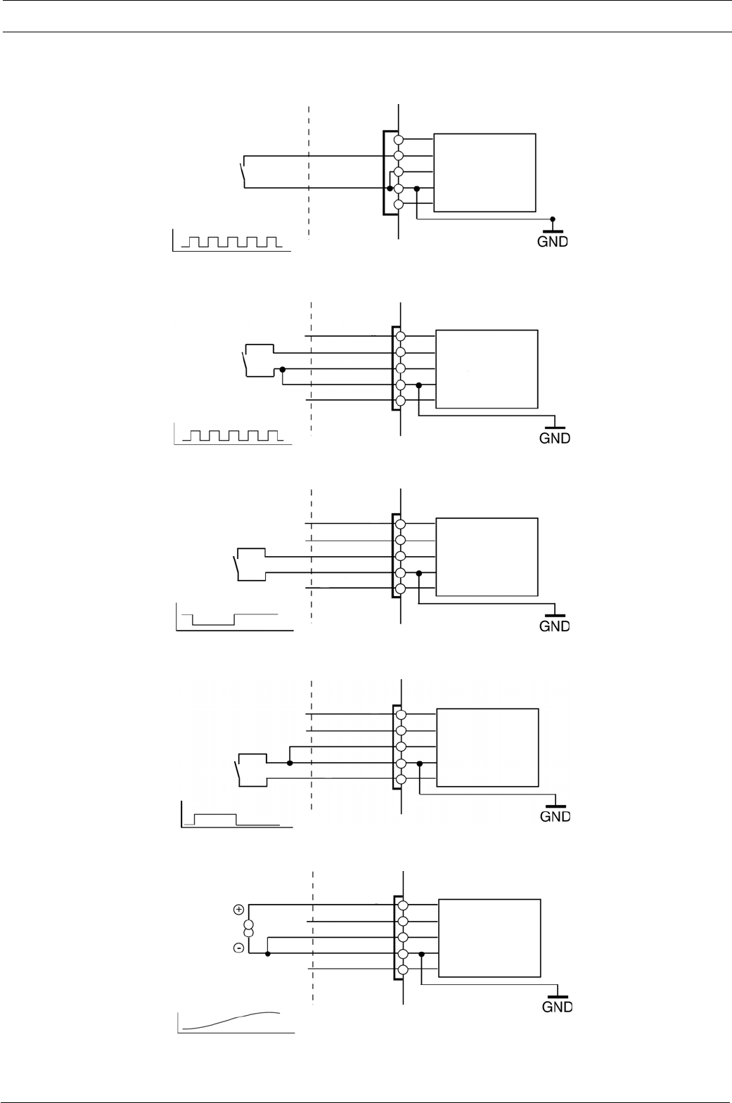
Circuit examples: universal signal cable
by customer Cable Pump, inside
“Pause“ function
Permanent contact,
e.g. from control room
“Auxiliary frequency“ function
“External analogue“ function
Permanent contact,
e.g. from control room
Analogue signal,
e.g. from magnetic inductive
flow meter
0/4-20 mA
External
activation
External
activation
3 blue/analogue
2 white/contact
1 brown/pause
4 black/GND
5 grey/auxiliary
3 blue/analogue
2 white/contact
1 brown/pause
4 black/GND
5 grey/auxiliary
3 blue/analogue
2 white/contact
1 brown/pause
4 black/GND
5 grey/auxiliary
Pulse rate,
e.g. contact water meter
External
activation
3 blue/analogue
2 white/contact
1 brown/pause
4 black/GND
5 grey/auxiliary
“External contact“ function
(ProMinent® universal signal cable)
five-core
Pulse rate,
e.g. contact water meter
External
activation
2 white/contact
4 brown/GND
“External contact“ function
(ProMinent® external/contact cable)
two-core
External
activation
Dulcodes UV-Desinfektionsanlage
Page 41
ProMinent®
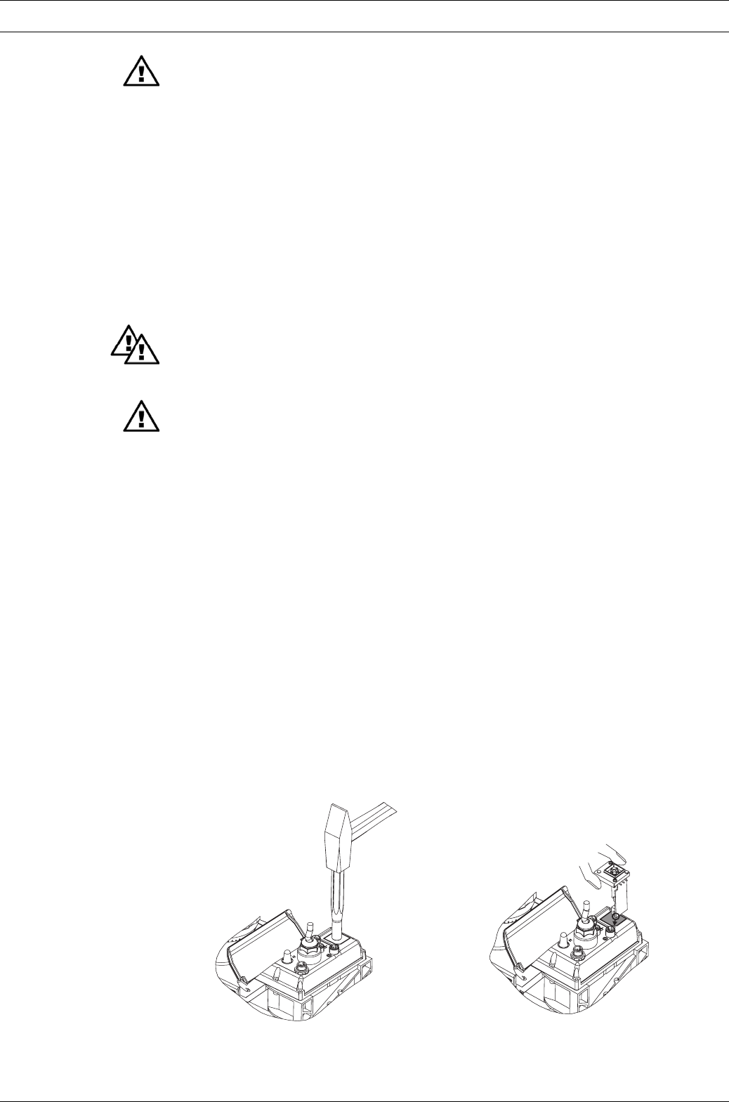
5.4 Retrofitting relays
(not in PROFIBUS® version)
Delivery range:
1relay circuit set with 2 screw fasteners
1relay cable set with socket
1seal
Press-out relay opening
WARNING
Disconnect the S3Ca from the mains power supply and rinse liquid end before commencing
work (see section 10)!
IMPORTANT
When preparing the opening, ensure that the punch is not forced through the entire pump
base!
Pump circuits may become damaged.
왘Place the S2Ca on a firm surface with the relay opening press-out section at the top (see
fig. 15)
왘Place a punch (dia. 8-15 mm) in the centre of the relay opening press-out section , and
strike briefly and sharply with a hammer (approx. 250 g)
왘If necessary clean up the edges of the opening
왘Remove the pressed out section from the S2Ca
Inserting the relay component 왘Hold the relay component with your right hand gripping the left and right hand edges of
the relay cover, and tilt the front end slightly to the left (see fig. 16)
왘Push the relay component through the relay opening, holding the upper corner of the lower
edge against the guide rail on the pump base, until the contact of the relay component has
reached the controller contact. (test: can you still move the end of the circuit back and
forth?)
왘Gently push the relay component right into the opening
왘Screw the relay cover firmly onto the housing using the screws provided
왘Insert the relay cable plug seal into the relay cover and screw on the plug (see fig. 18)
왘The pump is generally programmed ex-factory to ”drop-out action alarm relay“ and – if
fitted – ”pull-up action clock pulse generator relay“. If a switching function is required, the
pump can be reprogrammed at the Heidelberg plant (not necessary in PROFIBUS®-version).
IMPORTANT
• The universal signal cable, the external/contact cable and the level monitor cable should
not be less than 1.20 m long, otherwise cable recognition will fail.
Features of the S2Ca metering pumps
Fig. 15 Fig. 16
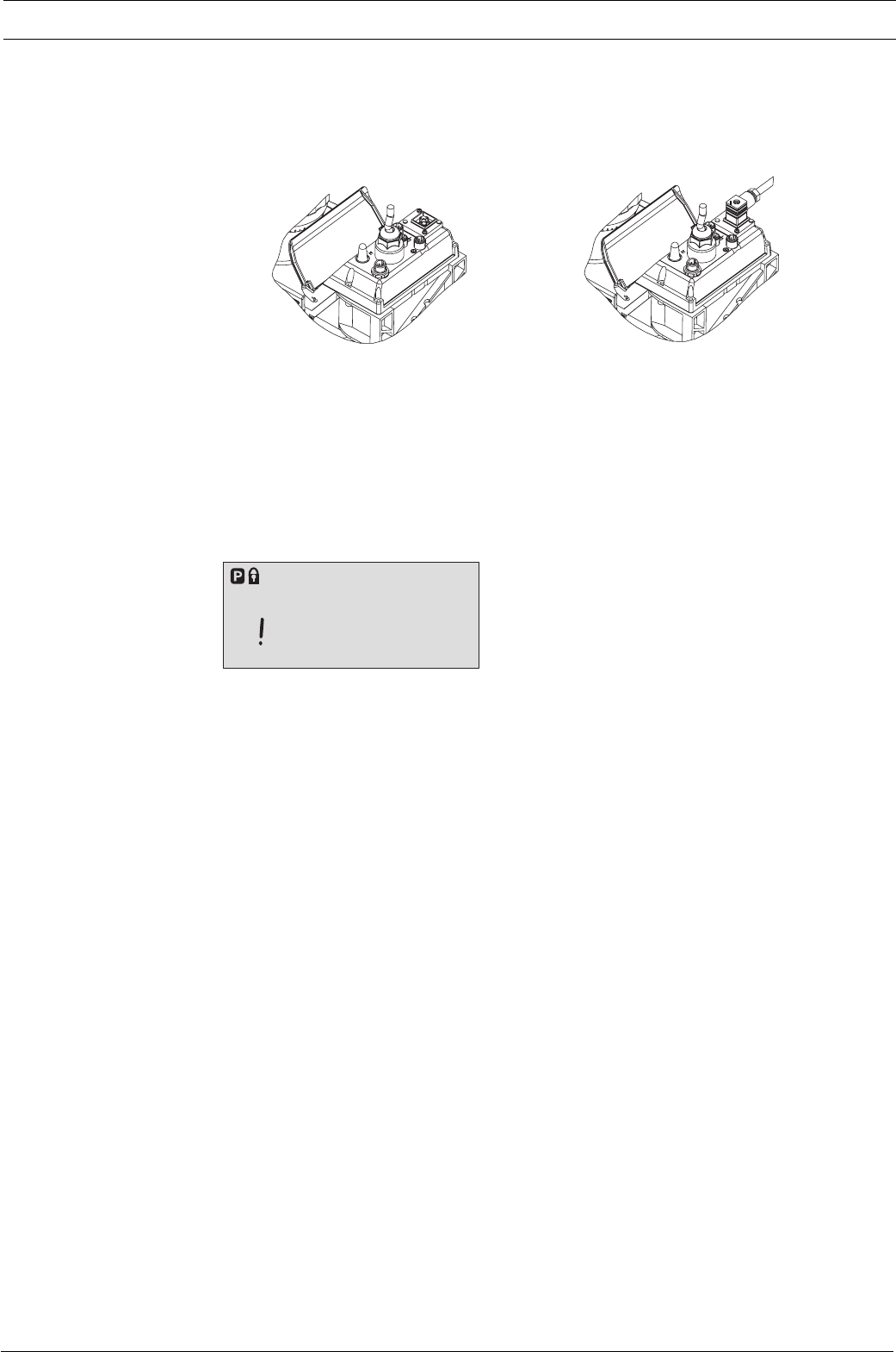
Page 42 ProMinent®
Dulcodes UV-Desinfektionsanlage
Set
Flow
Calib
Mem
ErrorPauseAux
Stop
Features of the S2Ca metering pumps / Control elements
Fig. 17 Fig. 18
6Control elements
Please acquaint yourself with the S2Ca control elements with the help of the “control elements
and key functions” overview!
Indicators The LCD display supports the operation and setting of the S2Ca with a range of indicators:
The indicators are interpreted as follows:
Symbol for P key: The S2Ca is in settings mode.
Close symbol: In a continuous display: lock (if code has been set).
In settings mode: indicates access to code menu.
Stop: The S2Ca has been stopped using the STOP/START key.
Aux: The S2Ca is pumping at the auxiliary frequency. In AUX menu:
the S2Ca is in the AUX menu.
Pause: The S2Ca has been stopped using the “pause” function
(external).
Error: A fault has occurred and the pump has been stopped.
Mem: An additional “memory” function has been set in the “contact”
and “batch” operating modes.
In CNTCT or BATCH menus (“mem” flashes): the memory
function can be set.
Calib: The S2Ca is in the CALIB menu.
In a continuous display (“calib” flashes”): Deviation from the
stroking rate from the value at the time of the calibration by
more than 10 percent (e.g. in the case of a stroke length of 40%
when it has been set to less than 30% or more than 50%).
Flow: The S2Ca is in the FLOW menu.
Set: The S2Ca is in the SET menu.
Exclamation mark: The number of strokes reached is above the maximum value
(99999) that can be shown in the LCD display.
NOTE
When calibrated, the S2Ca displays the feed rate and the feed capacity in l and/or in l/h or
in gal and/or g/h.
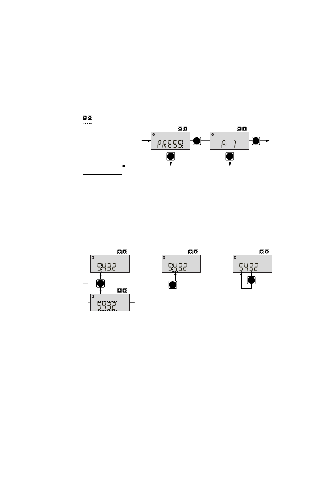
Dulcodes UV-Desinfektionsanlage
Page 43
ProMinent®
7Settings
NOTE
•Open out the fold-out page following the title page fully! There you will find the overviews
“control elements and key functions” and “operating settings diagram”.
•If no keys are pressed within a period of 1 minute, the S2Ca will return to a continuous
display.
Basic information for setting up the S2Ca
P
P
P
3 s P3 s
continuous
display
Set Set
= flashes
= Settings option
Confirm entries Press the P key briefly;
you will automatically move to the next menu option or to a continuous display.
Exit menu option
without confirming Press the P key for 3 s:
The entry is cancelled and you will return to a continuous display.
i
1x 2x
i
P
Incremental change
of a value Press the i key 1x;
you can toggle between altering the digits of a value (“change individual digits” = standard) or
incremental alteration of a value (“change a figure”).
Change adjustable values Press UP or DOWN arrow key;
The flashing digit or figure will start to increase or decrease incrementally.
Confirm adjustable values For “change individual digits”: confirm each digit using the P key. When the last digit has been
confirmed you will automatically move to the next menu option or to a continuous display.
For “change a figure”; press the P key 1x; you will simultaneously move to the next menu option
or to a continuous display.
Correct wrongly set digits Press the i key 2x;
you will go back to the first digit.
Settings
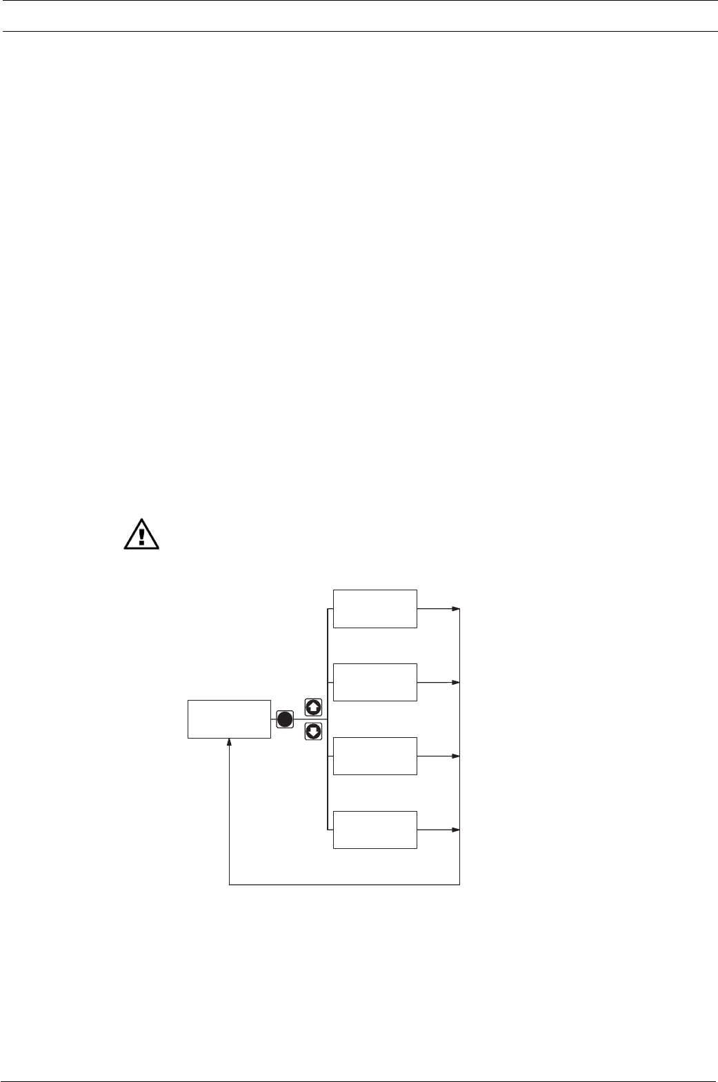
Page 44 ProMinent®
Dulcodes UV-Desinfektionsanlage
7.3 Select operating mode (MODE menu)
The following operating modes are selected via the MODE menu (depending upon identity
code, some operating modes may be absent):
•Manual: for operation by hand
(Identity code, control variant: manual, standard option)
•Analogue: for electronic control
(Identity code, control variant: analogue current)
Settings
7.1 Check adjustable values
Before setting up the S2Ca you can check the current settings of adjustable values:
Press the i key (“i” as in “info”) when the S2Ca is in continuous display mode (There is no P key
symbol in the LCD display).
Each time you press the i key you will see a different continuous display. The number of
continuous displays depends upon the identity code, the selected operating mode and the
connected accessories (see overview “continuous displays”).
7.2 Change to settings mode
If you hold down the P key for 2 seconds in any continuous display, the S2Ca will change to the
settings mode.
If CODE 1 is set, the code must be entered after pressing the P key.
The following menu options appear first in the settings mode (see also overview “operating/
settings diagram”):
•MODE menu
•CODE menu (optional)
•SET menu
•CLEAR window
In order to adapt the S2Ca to your process requirements you must:
1. Select the operating mode in the MODE menu.
2. If necessary enter the settings for this operating mode in the SET menu.
Exception: Timer and PROFIBUS®.
IMPORTANT
Note the diagram below!
P
2 s
Continuous
display
MODE
menu
SET
menu
CODE
menu
CLEAR
window
1.
2.
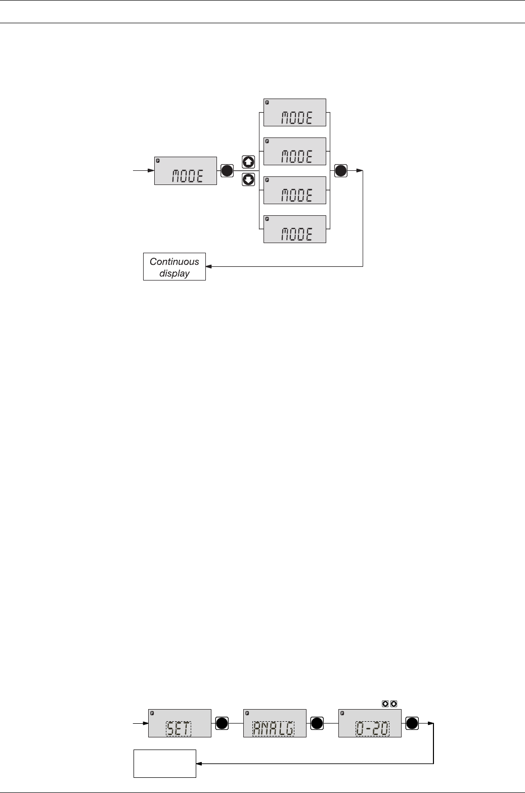
Dulcodes UV-Desinfektionsanlage
Page 45
ProMinent®
Settings
•Contact: for contact operation
(Identity code, control variant: external 1:1 / external with pulse control)
•Batch: for batch operation
(Identity code, control variant: external with pulse control)
P
Batch
Contact
ManualAnalog
Analog
Manual
Contact
Batch
- ANALOG
- MANUAL
- CONTACT
- BATCH
P
7.4 Settings for operating mode (SET menu)
NOTE
First select the operating mode in the MODE menu!
Exceptions: Timer and PROFIBUS®.
In the SET menu you can adjust various settings depending upon the selected operating mode.
The following programmable function settings menus appear in all operating modes:
•Calibrate (CALIB menu)
•Auxiliary frequency (AUX menu)
•Flow (FLOW menu, available only if flow monitor is connected)
See also section 7.5!
Further settings menus depend upon the selected operating mode.
7.4.1 Settings for “manual” operating mode
There are no other settings menus in the overall SET menu for the “manual” operating mode
apart from those described in 7.5.
7.4.2 Settings for “analogue” operating mode (ANALG menu)
In addition to those settings menus described in 7.5, there is an additional ANALG menu in the
overall SET menu for the “analogue” operating mode.
The stroke rate is controlled by an analogue electrical signal via the “external control” terminal.
You can select three signal-processing methods:
•0 - 20 mA: at 0 mA the S2Ca does not operate
at 20 mA the S2Ca operates at 180 strokes/min.
Between these two extremes the stroke rate is proportional to the electrical
signal.
PP P
Continuous
display
Set
mA
Set
Analog
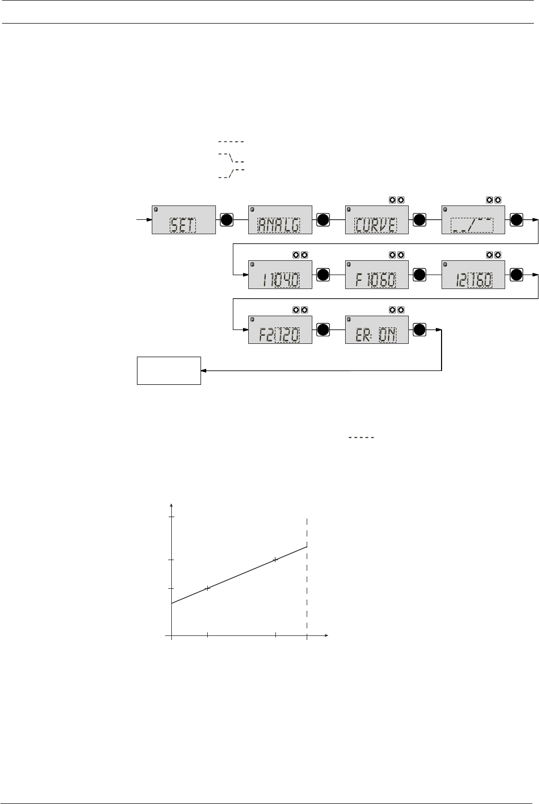
Page 46 ProMinent®
Dulcodes UV-Desinfektionsanlage
Settings
•4 - 20 mA: at 4 mA the S2Ca does not operate
at 20 mA the S2Ca operates at 180 strokes/min.
Between these two extremes the stroke rate is proportional to the electrical
signal.
For signals of below 3.8 mA a fault will be detected and the S2Ca will stop
(e.g. cable break).
•Curve: In the “curve” processing mode you can programme the S2Ca ratios.
There are 3 options available:
• = straight line
• = lower band
• = upper band
PP
PP P
PP P
P
Continuous
display
Set Set
Analog
Set
Analog
Set
Analog
Analog
mA
Set
Analog
Freq.
Set
Analog
Freq.
Set
Analog
mA
Set
Straight line:
The following symbol appears in the LCD display: .
You can enter any stroke frequency ratio for the S2Ca in proportion to the electrical signal.
You must enter two points P1 (I1, F1) and P2 (I2, F2). F1 is the stroke rate at which the pump
should operate at current I1: the straight line and the ratio are fixed accordingly:
I [mA]
I 1 I 2
F1
F2
F
max
020
P1
P2
Fig. 19
NOTE
Draw a diagram like the one above - with values for (I1, F1) and (I2, F2) - in order to set
the S2Ca to your required stroke rate!
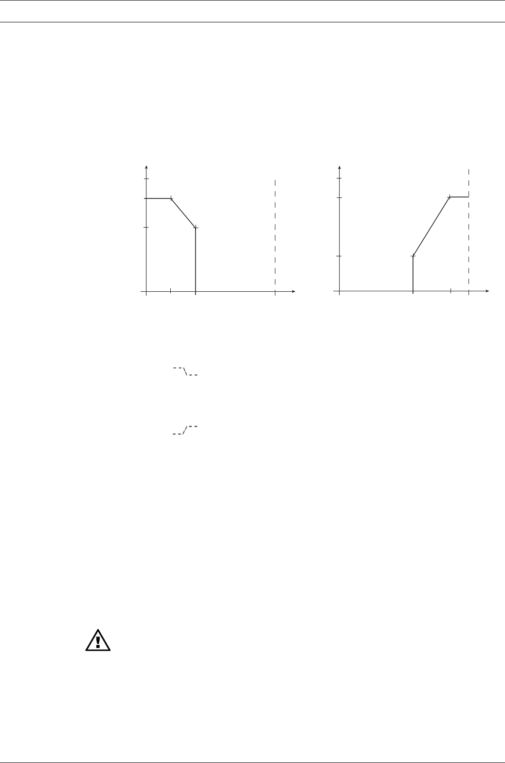
Dulcodes UV-Desinfektionsanlage
Page 47
ProMinent®
Settings
Lower/upper band:
This processing mode allows you to control a pump via an electrical signal as shown in the
diagrams below.
Lower band Upper band
e.g. Alkali pump e.g. acid pump
I [mA]
I 1 I 2
F2
F1
020
P1
P2
Fmax
I [mA]
I 1 I 2
F1
020
P1
P2
F2
F
max
Fig. 20 Fig. 21
Lower band:
The symbol appears in the LCD display. The S2Ca will operate below I1 at F1.
Above I2, the S2Ca ceases to operate. Between I1 and I2 the stroke rate is between F1 and F2,
proportional to the signal current.
Upper band:
The signal appears in the LCD display. The S2Ca will cease to operate below I1.
Above I2, the S2Ca will operate at F2. Between I1 and I2 the stroke rate between is F1 and F2,
proportional to the signal current.
The smallest processable difference between I1 and I2 is 4 mA.
Error processing In the “ER” (error) menu option you can activate an error processing function for the “curve”
mode. An error message appears for signals below 3.8 mA and the S2Ca stops.
7.4.3 Settings for “contact” operating mode (CONTCT menu)
In addition to those settings menus described in 7.5, there is an additional CONTCT in the
overall SET menu for the “contact” operating mode.
The operating mode “contact” allows you to activate a single stroke or a series of strokes. The
strokes can be activated by a pulse or via the “external control” terminal. This operating mode
is intended to transfer input pulses into a reduction (fraction) or small increase in strokes.
IMPORTANT
The factor resets to “1” if you change to a different operating mode.tity cod
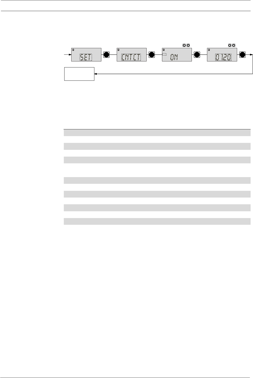
Page 48 ProMinent®
Dulcodes UV-Desinfektionsanlage
Settings
In the “contact - identity code: external with external pulse control” you can enter the number
of pulses after which a stroke should be carried out. “Contact - identity code: external with
external pulse control” is intended for small dosing quantities.
PPP
P
Continuous
display
Set Set
Mem
Contact
Set
Mem
Contact
The number of strokes per pulse depends upon the factor, which you can enter. This allows
you to vary to a certain extent the input pulses by a factor of 1.01 to 99.99 and/or reduce by a
factor of 0.01 to 0.99:
“Number of strokes activated = factor x number of input pulses”
Examples Factor Pulse (sequential) Stroke number (sequential)
Increase 11 1
21 2
25 1 25
99.99 1 99.99
1.50 1 1.5 (1 / 2)
1.25 1 1.25 (1 / 1 / 1 / 2)
Reduction 11 1
0.50 2 1
0.10 10 1
0.01 100 1
0.25 4 1
0.40 2.5 (3 / 2) (1 / 1)
0.75 1.33 (2 / 1 / 1) (1 / 1 / 1)
Explanation of increase At a factor of 1 For every 1 pulse, 1 stroke is activated
At a factor of 2 For every 1 pulse, 2 strokes are activated
At a factor of 25 For every 1 pulse, 25 strokes are activated
Explanation of decrease At a factor of 1 After 1 pulse, 1 stroke is activated
At a factor of 0.5 After 2 pulses, 1 stroke is activated
At a factor of 0.1 After 10 pulses, 1 stroke is activated
At a factor of 0.75 After 2 pulses, 1 stroke is activated,
then after 1 pulse, 1 stroke is activated,
then after 2 pulses, 1 stroke is activated etc.
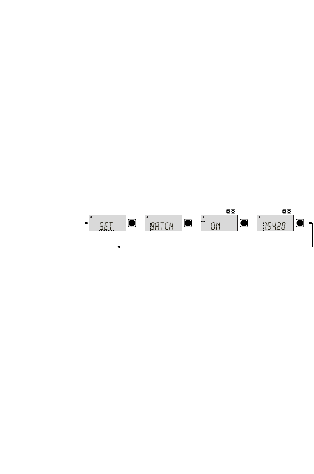
Dulcodes UV-Desinfektionsanlage
Page 49
ProMinent®
Settings
NOTE
If a remainder occurs when the factor is processed, the S2Ca counts up the remainder
values. When the sum reaches or exceeds “1” the S2Ca will activate a stroke. This ensures
that the stroke number corresponds exactly to the factor throughout the dosing operation.
The number of input pulses which have not been processed are stored by the S2Ca in the
stroke memory. The stroke buffer is limited to the batch size when memory is not activated
(- with “Memory” at 65535 stokes). You can delete it by switching to a different operating
mode.
You can optimally adapt the S2Ca to the respective process, e.g. in connection with contact
water meters.
“Memory” extension function
The “memory” extension function can be optionally activated (“mem” appears in the LCD
display). When “Memory” is activated the S2Ca adds any strokes which could not be carried
out up to the maximum capacity of the stroke buffer – 65535 strokes. If this maximum capacity
is exceeded the pump will register a fault.
7.4.4 Settings for “batch” operating mode (BATCH menu)
In addition to those settings menus described in 7.5, there is an additional BATCH menu in the
overall SET menu for the “batch” operating mode.
PP P
P
Continuous
display
Set Set
Mem
Batch
Set
Mem
Batch
L
The “batch” operating mode is a variant of the “contact” operating mode (see 7.4.3).
You can pre-select a stroke number (no breaks, whole numbers only from 1 to 65535) as well
as a feed quantity (batch). To switch between entries for “stroke number” and “feed quantity”
press the i key 1x in the corresponding menu option (see also overview “operating/settings
diagram”, fold-out page).
The “batch” operating mode is intended for large dosing quantities.
Metering can be actuated by pressing the P-key or via a pulse from the “external control
socket”.
The number of input pulses which have not been processed are stored by the S2Ca in the
stroke memory. The stroke buffer is limited to the batch size when memory is not activated
(- with “Memory” at 65535 stokes). You can delete it by switching to a different operating
mode.
“Memory” extension function
The “memory” extension function can be optionally activated (“mem” appears in the LCD
display). When “Memory” is activated the S2Ca adds any strokes which could not be carried
out up to the maximum capacity of the stroke buffer – 65535 strokes. If this maximum capacity
is exceeded the pump will register a fault.
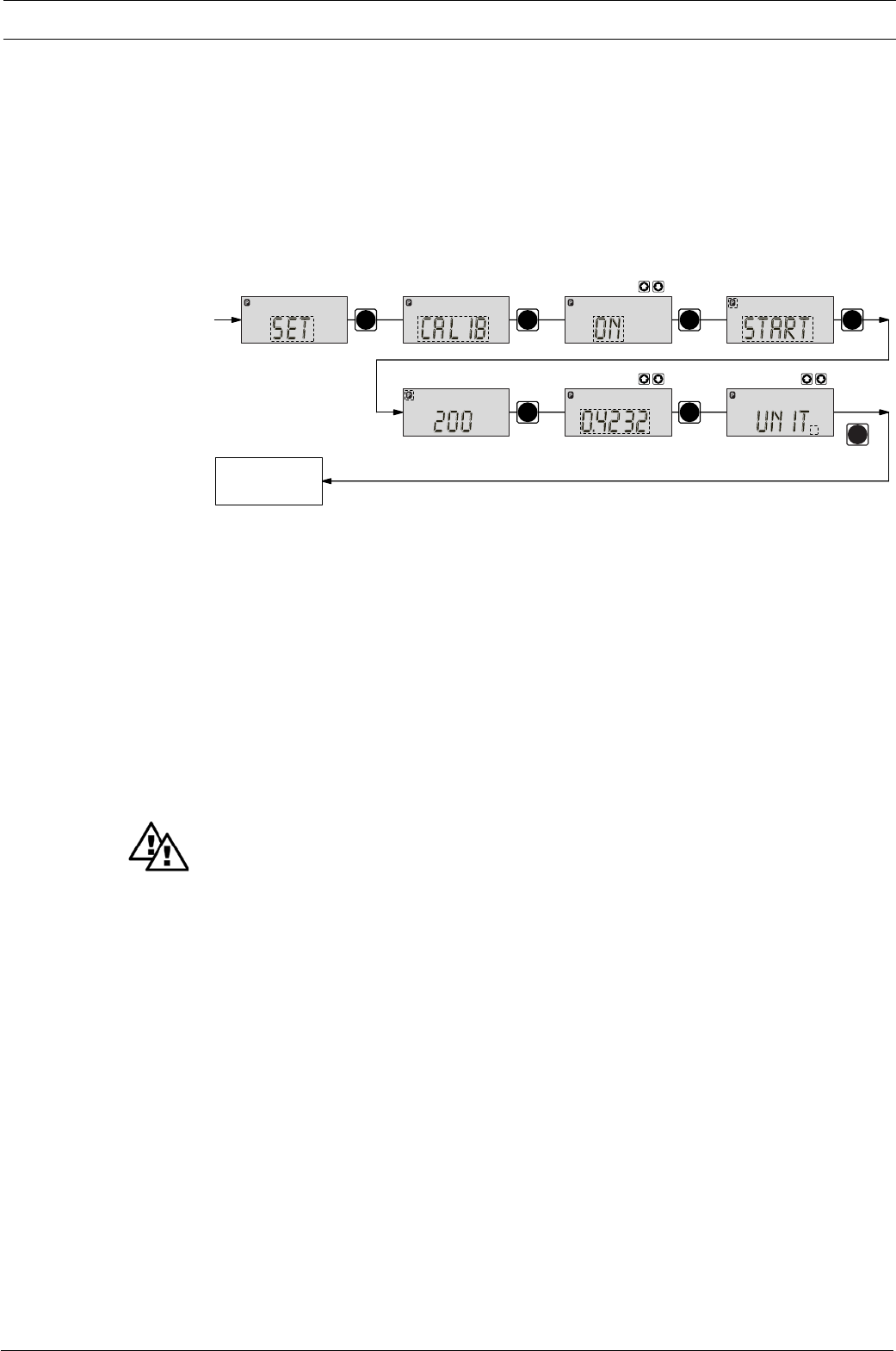
Page 50 ProMinent®
Dulcodes UV-Desinfektionsanlage
PP
PP P
P
Continuous
display
Set Set
Calib
Set
Calib
LSet
LSet
Calib
Set
Calib
N
The S2Ca can also run in calibration mode. The corresponding continuous displays show the
current dosing quantities or the feed rate.
The calibration is retained in the event of a change of the set stroke length by up to ±10 scale
rates percent (if the stroke length is set to 40 % the range is 30 % to 50 %). If the stroke length
is changed by more than ±10 scale rates percent the yellow warning light lights up, the perma-
nent display flashes and the flashing “Calib” indicator appears.
NOTE
•Do not go below 30 % stroke length (SEK type: 50 %).
This will significantly affect accuracy of calibration.
•Calibration becomes increasingly accurate the more strokes made by the S2Ca during
calibration (recommended: at least 200 strokes).
WARNING
If using a hazardous feed chemical, the following setting instructions ensure adequate
safety precautions are taken!
Calibration 왘Insert the suction tube into a measuring cylinder containing the feed chemical - the
discharge tubing must also be correctly installed (operating pressure,…!)
왘Suck up the feed chemical (press both arrow keys at the same time) when the suction tube
is empty
왘Note the liquid level in the measuring cylinder and the stroke length
왘Select the CALIB menu and go the first menu option using the P key
왘Select “ON” using an arrow key and change to the next menu option using the P key
왘To commence calibration, press the P key. The S2Ca starts to pump and displays the
number of strokes (“STOP” appears at regular intervals)
왘After a sufficient number of strokes, stop the S2Ca with the P key
왘Calculate the dosed quantity (difference between the original quantity and the quantity
remaining)
왘Enter this quantity in the next menu option and then change to the following menu option
by pressing the P key.
왘Select the unit (“L” or “gal”) in the “UNIT” menu with an arrow key and push the P-button.
The S2Ca is calibrated.
The corresponding continuous displays show the calibrated values.
The total stroke number and total litres are set during calibration to “0”.
The S2Ca is in the STOP status.
7.5 Settings for programmable functions (SET menu)
The following programmable function settings menus appear in all operating modes:
•Calibrate (CALIB menu)
•Auxiliary frequency (AUX menu)
•Flow (FLOW menu, available only if flow monitor is connected)
7.5.1 Settings for “calibration” function (CALIB menu)
Settings
P
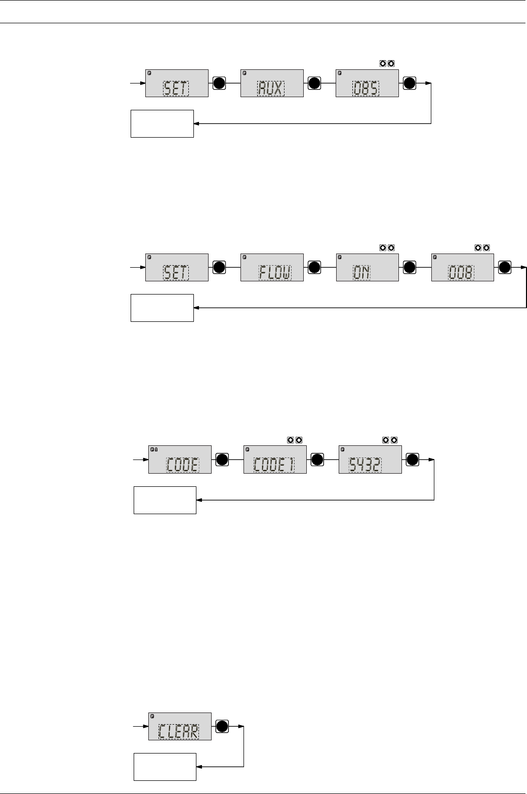
Dulcodes UV-Desinfektionsanlage
Page 51
ProMinent®
Settings
7.5.2 Settings for “auxiliary frequency” function (AUX menu)
PP
P
Continuous
display
Set
Freq.
Set
Aux
The programmable function “auxiliary frequency” allows switching to a different stroke
frequency, which can be set in the AUX menu. It can be activated via the “external control”
terminal. When the auxiliary frequency is activated, “aux” appears in the LCD display.
This auxiliary frequency overrides the current stroke frequency set for the selected operating
mode.
7.5.3 Settings for the “flow” function (FLOW menu)
PP P
P
Continuous
display
Set Set
Flow
Set
Flow
The flow menu only appears when a dosing monitor is connected to the “dosing monitor”
terminal. This dosing monitor registers each discharge stroke of the S2Ca at the discharge
connector and transmits it back to the S2Ca. If this response transmission is serially omitted
for a period set in the FLOW menu (due to failure or below-minimum dosing) the S2Ca stops.
7.6 Setting code (CODE menu)
The code menu is used to select whether you want to prevent access to parts of the settings
options.
PP P
Continuous
display
In the first menu option you can choose CODE 1 or CODE 2 (both use the same number).
•Select CODE 1 to prevent access to the settings mode (➀ in the overview “operating/
settings diagram”, fold-out page). In the next menu option, enter the number you wish to
use as the code.
•Select CODE 2 to prevent access to the settings options for directly alterable values in the
continuous displays (➁ in the overview “operating/settings diagram”, fold-out page). In the
next menu option, enter the number you wish to use as the code.
•Select NONE to remove a pre-set security lock.
7.7 Cancel total stroke number or total litres (CLEAR window)
In the CLEAR window you can delete the stored total stroke number and simultaneously the
total litres (= set to “0”). You may then press the P key briefly to exit this window.
The values displayed are counted incrementally from the point of commissioning the pump, or
from the last delete action.
P
Continuous
display
L
N

Page 52 ProMinent®
Dulcodes UV-Desinfektionsanlage
Operating
8Operating
This section describes all operating options available to you when the S2Ca is in continuous
display mode (no P key symbol in the LCD display).
WARNING
•For all metering pumps for metering inflammable media applies: Starting up and
emptying only supervised by a competent person.
NOTE
•Open out the fold-out page following the title page fully! There you will find the overviews
“control elements and key functions” and “operating/settings diagram”.
•Look at the overview “continuous displays”. This page shows you which displays are
available in which operating mode, and which values are directly alterable in the
corresponding continuous displays.
8.1 Manual operation
Set stroke length Stroke length is continually adjustable within a range of 0-100 %. The recommended stroke
length range, which will practically guarantee technical reproducibility, is 30-100 % (SEK type:
50-100 %).
NOTE
At low stroking rates (less than 1/3 maximum stroking rate) the controller switches to
digital stroking mode. This ensures adequate cooling of the motor at low stroking rates.
The following operating options are available via the different keys (see also figure on the next
page):
Stop/Start S2Ca To stop S2Ca: press STOP/START key.
To start S2Ca: press STOP/START key.
Start batch Press the P key briefly in “batch” operating mode.
Load factory settings Press the P key for 15 s to load factory calibration settings!
Current settings will be deleted.
Change to settings mode When you press the P key for 2 s in any continuous display the S2Ca will change to settings
mode (see section 7).
If CODE 1 is set, the code must be entered after pressing the P key.
Check adjustable values Each time you press the i key you will see a different continuous display. The number of
continuous displays depends upon the identity code, the selected operating mode and the
connected accessories.
Change directly
alterable values To change a value (see below) directly in the corresponding continuous display, press one of
the arrow keys until “set” appears in the LCD display. The delay has been programmed in to
prevent inadvertent changing of values.
If CODE 2 has been set, this code must be entered after pressing the arrow key.
Directly alterable values are as follows:
Stroke rate In “manual”, “contact” and “batch” operating modes:
The stroke rate can be altered in the “stroke rate” display.
Feed rate In “manual” operating mode
The feed rate can be altered in the “feed rate” display.
Factor The factor is the number of strokes activated by an external pulse or a press of the P key (in
“batch” mode only).
In “Batch” operating mode:
You can alter the factor from the “remaining strokes” display.
The S2Ca returns to the original continuous display a few seconds after the factor has been
reset.
Display program version Press the P key for 10 seconds to display the program version.
Example: “V1052” + “X1010”.
In the case of “LOAD3” release the key immediately!
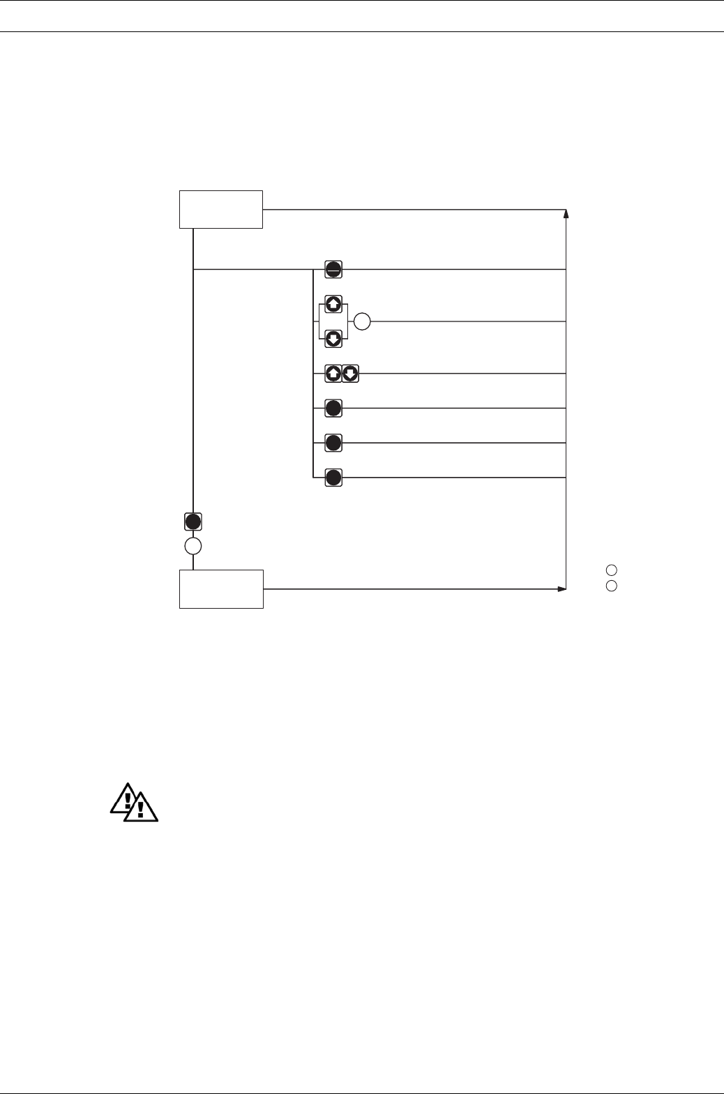
Dulcodes UV-Desinfektionsanlage
Page 53
ProMinent®
Operating / Troubleshooting
Batch size In “batch” operating mode:
The batch size can by changed from the “batch size/remaining litres” display.
The S3Ca returns to the original continuous display a few seconds after the batch size has
been reset.
Priming The “priming” function is activated by pressing both arrow keys at the same time (in “Stroke
rate” permanent display).
Cancel error Error messages are cancelled by pressing the P key briefly.
Settings
mode
P
P
P
i
STOP
START
Continuous
display
2 s
Stop/start pump
Change directly alterable values
= Security lock (CODE 1)
= Security lock (CODE 2)
Prime
Start batch (in "batch" operating mode only)
Cancel error
Check adjustable values
2
2
1
1
8.2 Remote control
Remote control of the S2Ca is possible via a control cable or PROFIBUS® (see Section 5.3 and
Chapter 7, ”Supplementary instructions for ProMinent® gamma/ L and ProMinent® Sigma
versions with PROFIBUS®“ as well as your documentation in the annex).
9Troubleshooting
WARNING
• EX-pump only: metering pumps and their peripheral equipment must be serviced by
specially trained or authorised personnel!
•Always take suitable precautions when using hazardous chemicals!
•Ensure the equipment is de-pressurised before working on the pump!
Pump primes despite completed stroke action and no venting
Cause Crystalline deposits on the ball seat because valves have dried out.
Remedy 왘Remove the suction sleeve from the chemical supply container and rinse out the liquid end
thoroughly.
왘If still unsuccessful, dismantle valves and clean.
Fluid is seeping from the top plate
Cause The liquid end is not sealed against the pump diaphragm.
Remedy 왘Tighten screws in the liquid end.
왘If unsuccessful, replace the diaphragm (see section 4.3).

Page 54 ProMinent®
Dulcodes UV-Desinfektionsanlage
Troubleshooting
Green LED indicator (operating display) is not lit
Cause Incorrect or no mains voltage.
Remedy 왘Use the recommended mains voltage as given in the voltage specification on the
nameplate.
Error Messages
Red LED display is lit, “Error” and “MINIM” flash in the display
Cause Fluid level in the chemical storage tank has reached “liquid level low, stage 2”.
Remedy 왘Fill the chemical supply container.
Red LED display is lit, “Error” and “ANALG” flash in the display
Cause S2Ca is in “analogue” operating mode, a fault routine has been programmed in the ANALG
menu and the operating current has fallen below 3.8 mA.
Remedy 왘Remedy low operating current.
왘Switch fault routine “OFF” (see section 7.4.2.).
Red LED display is lit, “Error” and “CNTCT” flash in the display
Cause S2Ca is in “contact” or “batch” operating mode and the extended function “memory” has been
set.
In addition a very large factor has been entered, too many contacts have been input or the P-
key has been pressed too often, resulting in an overflow of the stroke memory.
Remedy 왘Press the P-key, saved data will be deleted.
왘Change S2Ca set up.
Red LED display is lit, “Error” and “FLOW” flash in the display
Cause Dosing monitor not properly connected.
Remedy 왘Connect dosing monitor properly.
왘Press P-key.
Cause Dosing monitor has reported more defective strokes than have been set in the FLOW menu.
Remedy 왘Press P-key.
왘Investigate the cause and remedy.
Red LED is lit. “Error” appears in the display and “MOTOR” is flashing
Cause The motor is not operating accurately because the backpressure is too high.
Remedy 왘Reduce backpressure.
왘Press the P key (reset key).
Cause The motor is overheating.
Remedy 왘Check ambient temperature (max. 40 ºC).
왘Allow motor to cool down.
왘Press the P key (reset key).
Cause Other motor fault.
Remedy 왘Call ProMinent.
왘Press the P key (reset key).
Red LED is lit. “Error” appears in the display and “TEMPERATURE” is flashing
Cause The temperature in the pump housing is too high because the ambient temperature is too high.
Remedy 왘Reduce ambient temperature.
왘Allow motor to cool down.
왘Press the P key (reset key).
Cause The temperature in the pump housing is too high because the pump is consuming too much power.
Remedy 왘Check installation, rectify if necessary.
왘Allow motor to cool down.
왘Press the P key (reset key).
Dulcodes UV-Desinfektionsanlage
Page 55
ProMinent®
Troubleshooting / Decommissioning and disposal
Red LED display is lit, “Error” appears in the display and “FAN” is flashing
Cause Fault related to fan in pump housing.
Remedy 왘Check fan and replace if necessary.
왘Press the P key (reset function).
Red LED display is lit, “Error” appears in the display and “SYSTEM” is flashing
Cause Controller fault.
Remedy 왘Disconnect the pump from the mains and reconnect.
If the error message continues, send the pump back to ProMinent.
Red LED lights up, “Error” appears in the display and “Menu” flashes.
Cause Stroke buffer full
Remedy 왘Rectify fault
왘Press P key (Make a note of what effect this has on your process).
All other Errors
Please contact your ProMinent branch or representative!
Fault Signals
Yellow LED display is lit
Cause Liquid level in chemical storage tank has reached “liquid level low, stage 1”.
Remedy 왘Fill chemical storage tank.
Yellow LED Display is lit and “calib” flashes
Cause The pump is calibrated and the stroke length deviates by more than ±10 % from the value at
the time of calibration.
Remedy 왘Reset the stroke length or calibrate the pump again to the desired stroke length.
10 Decommissioning and disposal
Decommissioning
WARNING
•EX-pump only: metering pumps and their periphery must be maintained or
decommissioned by qualified or authorised personnel!
•For all metering pumps for metering inflammable media applies: Starting up and
emptying only supervised by a competent person.
•When decommissioning the pump, ensure that all dirt and chemicals are cleaned from
the housing and particularly the liquid end.
•Always take suitable precautions when using hazardous chemicals!
•Ensure that the equipment is de-pressurised!
왘Disconnect the pump from the mains.
왘Empty the liquid end by placing the pump on its head and allowing the chemical to drain
out.
왘Rinse the liquid end with a suitable material, thoroughly rinse the liquid end after use with
hazardous materials!
If decommissioning is only temporary, maintain the correct storage conditions:
Storage temperature: -10 to +50 °C
Air humidity: < 92 % relative humidity
Disposal
WARNING
Spring under tension!
Take particular care when disassembling the pump as the return spring (Item 5, Chapter 2.2)
is under considerable mechanical tension!
IMPORTANT
Observe your locally applicable regulations (particularly with regard to electronic scrap and
gear oil)!

Page 56 ProMinent®
Dulcodes UV-Desinfektionsanlage
11 Spare parts and accessories
CAUTION
The assembly and installation of ProMinent® metering pumps with other-make parts that
are not tested and recommended by ProMinent are not permitted and can lead to personal
injury and damage to property for which no liability shall be accepted!
Spare parts
You will find the order numbers for the wearing parts in the exploded view drawings in the
annex. If you require further parts, please order the “Spare parts list ProMinent® Sigma/ 2”.
Actuator for automatic stroke adjustment, setting time approx. 1 sec for 1% stroke length,
feedback potentiometer 1k Ohm enclosure rating IP 54.
Adjuster comprising actuator and incorporating servo controller for stroke length adjustment
via standard signal. Standard signal input 0/4-20 mA, corresponds to stroke length 0 – 100 %.
Manual to automatic mode switch, switch for stroke length adjustment in manual mode,
mechanical position display of 0/4-20 mA actual stroke length value output for remote display.
Variable speed motors with integrated speed changer (Identcode characteristic V)
Power supply 1 ph 230 V, 50/60 Hz, 0.37 kW
Optional external control via 0/4-20 mA
Speed controllers in metal casing (Identcode characteristic Z)
The speed controller kit comprises a speed changer and a 0.37 kW variable speed motor.
Float switches
2-stage, with 2 m connection cable
Alarm relays
For signalling faults
Alarm and pacing relays
For cyclic timing of other devices and for signalling faults.
Control cables
Universal control cable 5-core/2.5 and 10 m
External contact cable 2-core/2.5 and 10 m
Foot valves
With intake filter and non-return ball for connection at end of intake line.
Metering valves
With spring-loaded non-return ball for metering in open or closed systems and for mounting
the metering line.
Backpressure valves
For exact metering at low operating pressure or as overflow safety valve.
Accumulators
For pulsation damping in long metering lines.
Metering monitors
For monitoring metering operations. After an adjustable number of non-acknowledged metering
strokes, a fault is indicated and the metering pump shut down.
Intake assemblies
With foot valve and float switch for expendable packing drums or metering tanks.
Metering tanks
From 35 to 1000 l capacity with lockable screw cover and necessary accessories.
Manual/electric stirrers
For mixing and preparing metering solutions.
Spare parts and accessories

Dulcodes UV-Desinfektionsanlage
Page 57
ProMinent®
Motor datasheets are available for further information.
Special motors and special motor flanges are possible on request.
Motor data sheet
Motor-Typ AF 63/4C-7 Leistungsfaktor 0,66
motor type power factor
type du moteur facteur de puissance
Maschinenart 3-Ph. Motor Wirkungsgrad 88 %
type of machine efficiency
désignation rendement
Schutzart IP55 Bemessungsfrequenz 50 Hz
degree of protection rated frequency
degré de protection fréquence nominale
Bauform IMB5 Bemessungsdrehzahl 1370 U/min
mounting rated speed rpm
construction vitesse nominale t/mn
Bemessungsleistung 0,25 kW Wärmeklasse F
rated output temperature class
puissance nominale class d’isolement
Bemessungsspannung / ∆Anzugsstrom 3,2 fach
rated voltage 400/230 V starting current fold
tension nominale courant de démarrage fois
Bemessungsstrom 0,94/1,62 A Anzugsmoment 2,1 fach
rated current starting torque fold
courant nominale couple de démarrge fois
Geprüft nach DIN EN 60034 Kippmoment 2,3 fach
tested in acc. with pull-out torque fold
contrôlé selon couple de décrochage fois
PTB Nr. ohne EX-Schutz Umgebungstemperatur max. 40 °C
without EX-protection ambient temperature
température ambiante
Schaltung / ∆
connection
branchement
Anmerkung 400/230 V
comments 380-420/220-240 V (50 Hz)
observation
ProMinent
Pumpentyp S2Ca HM _ _ T _ _ _ _ U _ _ _ _ _ _
Motor Datenblatt / Motor data sheet / Fiche technique pour moteur
Bestell Nr. 1011036 Hersteller ATB
order no. / no. de commande producer / producteur
ProMinent Dosiertechnik GmbH ·69123 Heidelberg ·Germany Nr./No. MD - 1011036 Datum/Date 28.02.2002
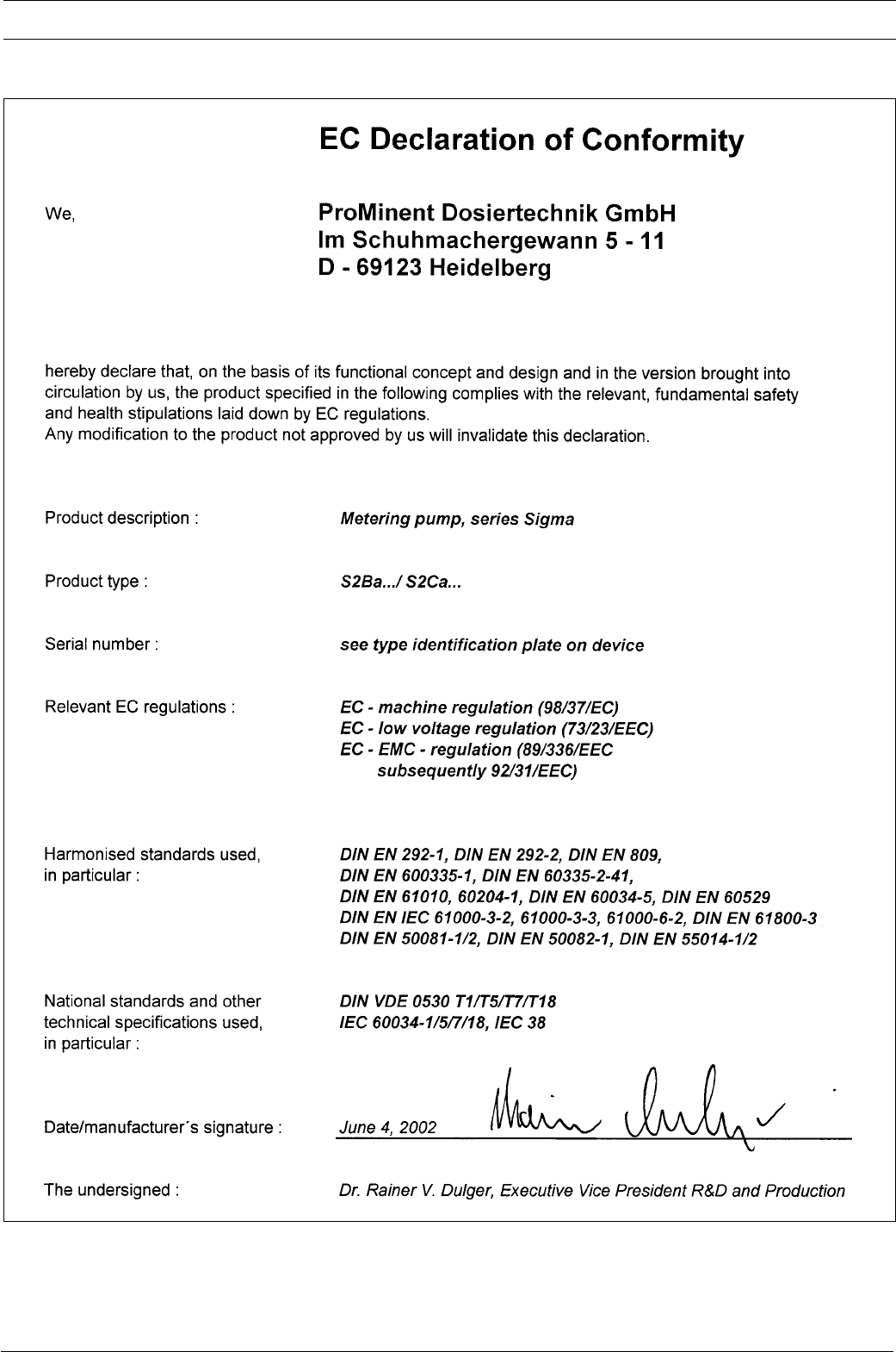
Page 58 ProMinent®
Dulcodes UV-Desinfektionsanlage
EC Declaration of Conformity
For pumps without Ex protection:
For pumps with Ex protection:
the EC conformity declaration for the pump for explosion-threatened workplaces is supplied with the pump.
The EC conformity declarations, the EC series prototype test reports and the operating manuals for the individual components
are also supplied with the pump.
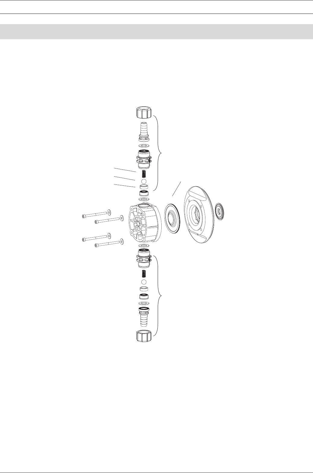
Dulcodes UV-Desinfektionsanlage
Page 59
ProMinent®
Exploded diagrams of liquid ends
Delivery unit Sigma/ 2 350-DN 25 PVT for identity code types: S2Ba/S2Ca 04350, 07120, 07220
Delivery unit Sigma/ 2 130-DN 15 PVT for identity code types: S2Ba/S2Ca 12050, 12090, 12130
Spare parts kit FM 350 PVT Order No. 740325
Spare parts kit FM 130 PVT Order No. 740324
*The listed items are constituent parts of the spare part kit.
** Special accessories (not included in spare part kit).
Subject to technical modifications.
Fig. 22
61_05-104_00_99-03
Valve spring *
Valve ball *
Ball seat *
Diaphragm FM 120 Order No. 1010285
Valve assy DN 15/PVT* Order No. 792517
Valve assy DN 15/PVT* Order No. 792517
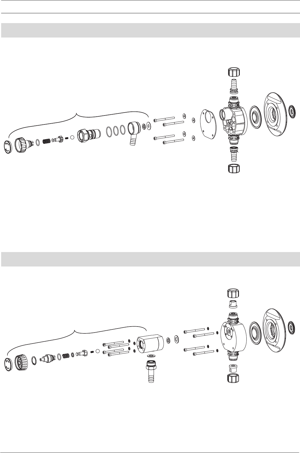
Page 60 ProMinent®
Dulcodes UV-Desinfektionsanlage
For other spare parts see delivery unit without overflow valve (see P. 56).
Subject to technical modifications.
Delivery unit Sigma/ 2 350-DN 25 PVT for identity code types: S2Ba/S2Ca 04350, 07120, 07220
Delivery unit Sigma/ 2 130-DN 15 PVT for identity code types: S2Ba/S2Ca 12050, 12090, 12130
Exploded diagrams of liquid ends
Fig. 23
61_05-104_01_00-03
Overflow valve assy 12 bar PVA Order No. 1018572
Overflow valve assy 10 bar PVA Order No. 1018947
Overflow valve assy 7 bar PVA Order No. 740811
Overflow valve assy 4 bar PVA Order No. 740812
Fig. 24
61_05-104_01_01-03_2
Overflow valve assy 16 bar SSA Order No. 1019246
Overflow valve assy 12 bar SSA Order No. 740813
Overflow valve assy 7 bar SSA Order No. 740815
Overflow valve assy 4 bar SSA Order No. 740814
Delivery unit Sigma/ 2 350-DN 25 SST for identity code types: S2Ba/S2Ca 04350, 07120, 07220
Delivery unit Sigma/ 2 130-DN 15 SST for identity code types: S2Ba/S2Ca 12050, 12090, 12130, 16050, 16090, 16130
For other spare parts see delivery unit without overflow valve (see P. 58).
Subject to technical modifications.
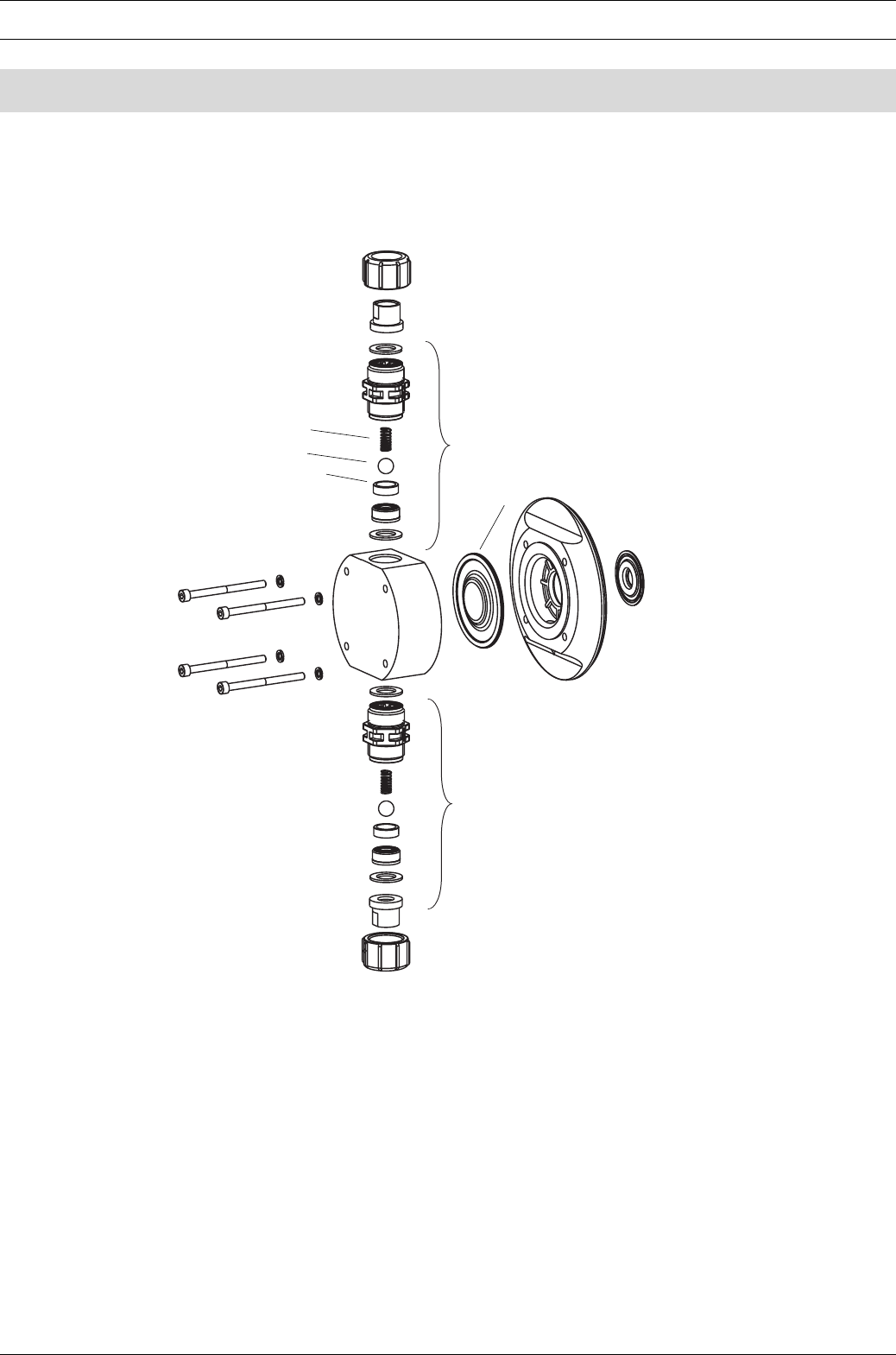
Dulcodes UV-Desinfektionsanlage
Page 61
ProMinent®
Exploded diagrams of liquid ends
Delivery unit Sigma/ 2 350-DN 25 SST for identity code types: S2Ba/S2Ca 04350, 07120, 07220
Delivery unit Sigma/ 2 130-DN 15 SST for identity code types: S2Ba/S2Ca 12050, 12090, 12130
Fig. 25
61_05-104_01_01-03_2_norm
Spare parts kit FM 350 SST without valve Order No. 740327
Spare parts kit FM 350 SST with 2 valves Order No. 740329
Spare parts kit FM 130 SST without valve Order No. 740326
Spare parts kit FM 130 SST with 2 valves Order No. 740328
*The listed items are constituent parts of the spare parts kit.
** Special accessories (not included in spare parts kit).
Subject to technical modifications.
Spring **
Ball *
Ball seat *
Valve assy DN 10/SST* Order No. 809459
Diaphragm FM 050 Order No 1010279
Diaphragm FM 065 Order No. 1010282
Valve assy DN 10/SST* Order No. 809459
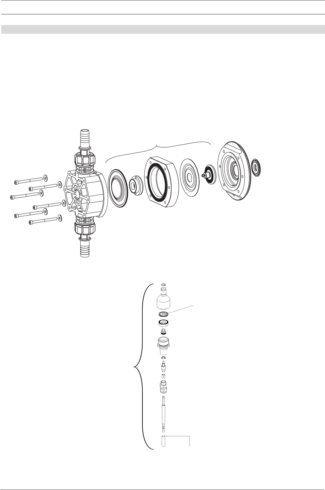
Page 62 ProMinent®
Dulcodes UV-Desinfektionsanlage
Exploded diagrams of liquid ends
Retrofit kit double diaphragm S2Ba/S2Ca
Fig. 26
61_05-104_00_98-03_2
*These items belong to the retrofit kit.
Subject to technical modifications.
Diaphragm failure detector *
Lense Order No. 792807
S1Ba Retrofit kit double diaphragm FM 050 Order No. 1009846
S1Ba Retrofit kit double diaphragm FM 065 Order No. 1009848
S1Ba Retrofit kit double diaphragm FM 120 Order No. 1009850
S1Ca Retrofit kit double diaphragm FM 050 Order No. 1009847
S1Ca Retrofit kit double diaphragm FM 065 Order No. 1009849
S1Ca Retrofit kit double diaphragm FM 120 Order No. 1009851
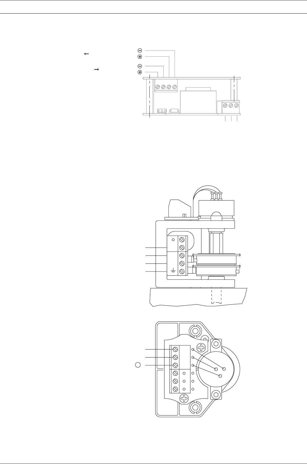
Dulcodes UV-Desinfektionsanlage
Page 63
ProMinent®
Wiring diagram
Stroke actuator wiring diagram
Wiring diagram for stroke length adjuster
N
P1
P2
E
-
Sig.
V+
3
2
1
5
6
7
4321
321
Feedback signal mA
Input signal mA
PE N L
Power supply
Power supply
