Sigmatek and Co KG AMM002 Shoe Electronics User Manual MS 021
Sigmatek GmbH & Co KG Shoe Electronics MS 021
user manual

MS 021
MS Shoe Electronics
Date of creation: PRELIMINARY
Version date: PRELIMINARY
Article number: 21-891-101-E

Publisher: SIGMATEK GmbH & Co KG
A-5112 Lamprechtshausen
Tel.: 06274/4321
Fax: 06274/4321-18
Email: office@sigmatek.at
WWW.SIGMATEK-AUTOMATION.COM
Copyright © 2015
SIGMATEK GmbH & Co KG
All rights reserved. No part of this work may be reproduced, edited using an electronic system, duplicated or distrib-
uted in any form (print, photocopy, microfilm or in any other process) without the express permission.
We reserve the right to make changes in the content without notice. The SIGMATEK GmbH & Co KG is not responsible
for technical or printing errors in the handbook and assumes no responsibility for damages that occur through use of
this handbook.
SHOE ELECTRONICS MS 021
PRELIMINARY Page 1
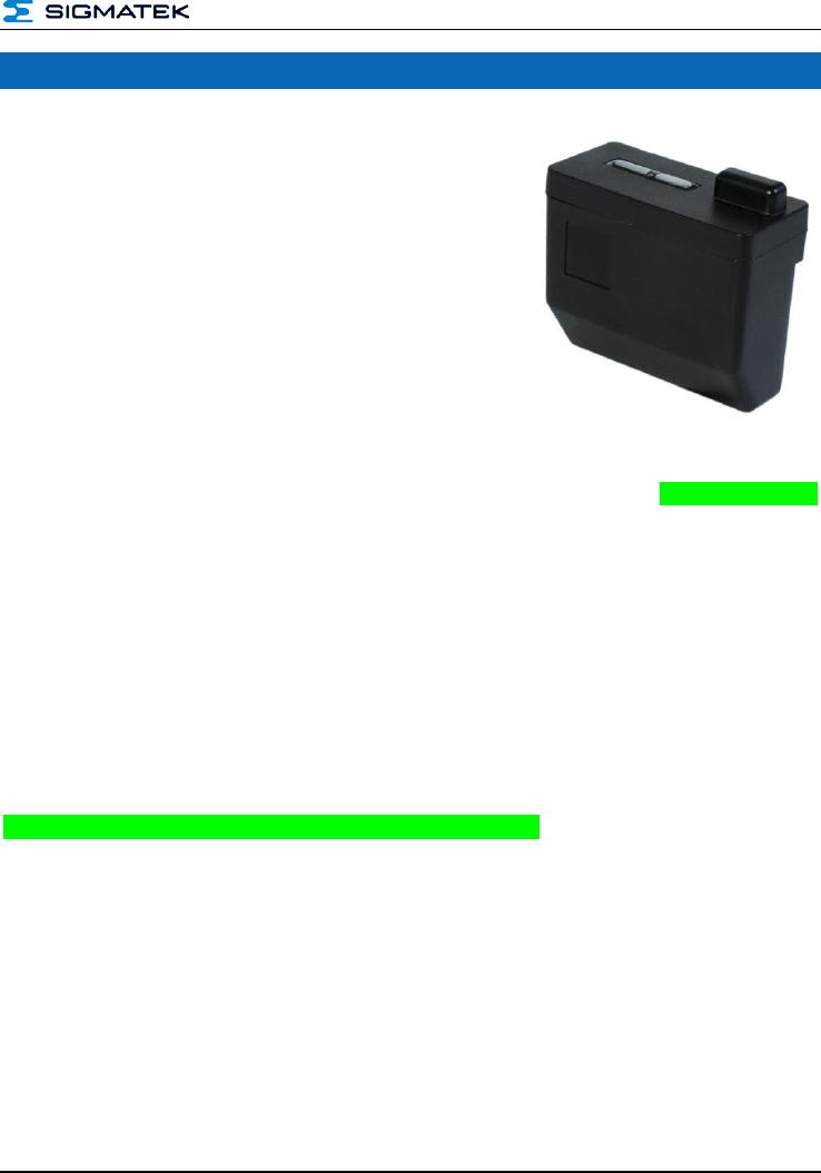
Shoe Electronics MS 021
This component has:
2-channel evaluation of pressure and speed (with MS
041)
control option for vibration motor
(on MS 041)
monitored control of an ultrasound emitter
2.4 GHz wireless system
The ultrasound output is required for the operator positioning (shoe), the sensor evaluation
for detecting the triggering pattern and the transmission path for communication with the
machine electronics (MS 012).
To use the MS 021 module in an application, an MS 012 and Safety CPU module that regu-
lates the synchronized communication with the safety modules using safe bus telegrams is
also required. This also includes
processing the safe application and
the distribution of configuration data to remote safety modules.
the integrated Li-Ion battery is charged using the MS 052

MS 021 SHOE ELECTRONICS
Page 2 PRELIMINARY
Contents
1 Basic Safety Guidelines .......................................................... 4
1.1 General Safety Information .......................................................... 4
1.2 Further Safety Guidelines ............................................................ 5
1.3 General Requirements ................................................................. 6
2 Safety Conformity ................................................................... 8
2.1 Functional Safety Standards ....................................................... 8
2.2 Safety-Relevant Parameters ........................................................ 8
3 Delivery Condition ................................................................... 9
4 Installation ............................................................................... 9
5 System Architecture ............................................................. 10
6 Technical Data ....................................................................... 11
6.1 ADXL Interface Specifications ................................................... 11
6.2 FSR Interface Specifications ..................................................... 11
6.3 Vibration Motor Interface Specifications .................................. 12
6.4 Configuration Interface Specifications ..................................... 12
6.5 Electrical Requirements ............................................................. 12
6.5.1 Environmental Conditions ................................................................. 13
6.5.2 Miscellaneous ................................................................................... 13
7 Guidelines for Handling the Battery .................................... 14

SHOE ELECTRONICS MS 021
PRELIMINARY Page 3
8 Safety Guidelines for Handling Li-Ion Batteries *) ............... 15
8.1 Battery Data Sheet ...................................................................... 17
9 Mechanical Dimensions ........................................................ 18
10 Connector Layout .................................................................. 19
11 FCC Statement ....................................................................... 21
MS 021 SHOE ELECTRONICS
Page 4 PRELIMINARY
1 Basic Safety Guidelines
1.1 General Safety Information
If the safety guidelines are not followed, danger to personnel can arise that could lead to
serious injury or in worst cases, death. In less serious cases, systems and equipment can
be damaged.
The following symbols identify the individual risks as well as the degree of seriousness;
their respective meanings are briefly explained. You should therefore familiarize yourself
with the safety symbols and their meanings to prevent dangers and risks.
DANGER
DANGER
Identifies an immediate danger with high risk, which
can lead to immediate death or serious injury if not
avoided.
WARNING!
WARNING!
Identifies a possible danger with a mid-level risk,
which can lead to death or (serious) injury if not
avoided.
CAUTION
CAUTION
Identifies a low risk danger, which can lead to injury or
property damage if not avoided.
SHOE ELECTRONICS MS 021
PRELIMINARY Page 5
1.2 Further Safety Guidelines
Warning, dangerous electrical voltage
Hot surface warning
Danger for ESD-sensitive components
This symbol identifies important or additional infor-
mation regarding the operation of the safety modules.
MS 021 SHOE ELECTRONICS
Page 6 PRELIMINARY
1.3 General Requirements
Technical
Documentation
This technical documentation is a component of this product.
This document must be accessible in the vicinity of the
machine, since it contains important instructions.
The technical documentation should be included in the
sale, rental or transfer of the product.
Acceptance of Safety
Guidelines
Before handling the product to which this documentation be-
longs, the operating instructions and safety guidelines must be
read. SIGMATEK GmbH & Co KG accepts no liability for
damages resulting from non-compliance with the safety guide-
lines or the relevant regulations
Acceptance of the safety guidelines and the explanations in this
document, as well as the Safety System handbook are a basic
requirement for proper use. Therefore, read this operating man-
ual thoroughly and familiarize yourself with each of them in
detail.
More information on standards and regulations etc. can be
found in the system handbook
Qualified Personnel
Installation, assembly, programming and initial start-up, opera-
tion, maintenance and decommissioning of control and automa-
tion technology products in general, as well as safety-related
products especially, can only be performed by qualified person-
nel.
Qualified personnel in this context are people, who have com-
pleted training or have trained under supervision of qualified
personnel and have been authorized to operate and maintain
safety-related equipment, systems and facilities in compliance
with the strict guidelines and standards of safety technology.
SHOE ELECTRONICS MS 021
PRELIMINARY Page 7
Designated Use
The Safety modules are designed for use in safety-oriented
applications and meet the required conditions for safety opera-
tion in compliance with Performancelevel e (PL e), in accord-
ance with EN ISO 13849-1 and SIL 3 or SIL CL 3 in accordance
with EN 62061.
For your own safety and the safety of others, use safety mod-
ules for their designated purpose. Correct EMC installation as
well as proper transport and storage are also included under
designated use.
Non-designated use consists of
any change made to the safety modules of any kind.
the use of damaged safety modules.
the use of the safety module outside of the instructions
described in this handbook.
the use of the safety module outside of the technical
data described in this handbook.
Operator Due Diligence
The operator must ensure that
the Safety modules are to be used for their designated
purpose only.
the Safety modules are to be operated in error-free,
fully functional condition only.
only sufficiently qualified and authorized personnel op-
erate the Safety modules.
the documentation is complete and in readable condition and
available at the site of operation.
MS 021 SHOE ELECTRONICS
Page 8 PRELIMINARY
2 Safety Conformity
2.1 Functional Safety Standards
SIL 3 or SIL CL 3 according to 62061
PL e, Cat. 4 according to 13849
2.2 Safety-Relevant Parameters
Machine electronics
Safety Parameters
MS 021
2.69 * 10^-09h
871 years
SHOE ELECTRONICS MS 021
PRELIMINARY Page 9
3 Delivery Condition
The individual SIGMATEK Safety components are delivered in specific hard and software
configurations. Any change of this configuration, which exceeds the options specified in this
documentation, is not authorized and invalidates the warranty from SIGMATEK GmbH & Co
KG.
4 Installation
Before assembling, disassembling or wiring the MagicShoe system, the entire system must
be placed in a safe, voltage-free condition.
The MS 021 shoe electronics is powered by an integrated 3.7 V Li-Ion battery. This is be-
fore initial start-up with the MS 052 charging station provided.
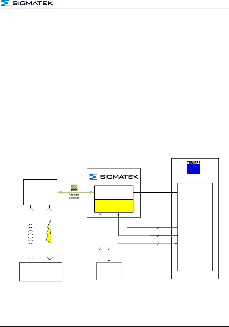
Fig 1: System architecture
Ethernet
TCP/IP
ultrasound
Safety
CPU
Machine PLC
HMI
Foot switch
CIPC
Evaluation Unit
CSCP 011
Not-Halt / Auf
2-k
2-k
2-k
2-k
2-k
radio
Operational Unit
PS101+CP111
SCP011-STO081

MS 021 SHOE ELECTRONICS
Page 10 PRELIMINARY
5 System Architecture
For the system architecture of the safety-related MagicShoe control as shown above, a PS
101, CP 111, Safety CPU of type SCP 111 as well as an STO 081, the MS 012 evaluation
unit and the operator-side components (shoe) MS 021, MS 031, MS 041 and MS 061 are
required. A dangerous situation can therefore only occur in such a configuration.
After configuration, the safety-related application is located in the Safety CPU and is opera-
tional depending on the CP 111. The CP 111 is also needed to establish the communica-
tion between the Safety CPU and the design tool (SafetyDesigner). The PS 101 is required
to supply all S-DIAS components and cannot be removed.
With a valid configuration file on an SD card, the Safety CPU can also be configured inde-
pendently of the design tool (SafetyDesigner). More information can be found in the chapter
"Using the microSD card". With regard to the configuration using the design tool, the Safe-
tyDesign handbook must be consulted.
SHOE ELECTRONICS MS 021
PRELIMINARY Page 11
6 Technical Data
6.1 ADXL Interface Specifications
To evaluate the triggering pattern, the acceleration in the toe area of the shoe is recorded
3-dimensionally. The interface between the sensor and the evaluating CPU in made via
SPI.
Because of the 2-channel principal, two acceleration sensors are used.
Number
2
Type
ADXL345 from analog device
Interface
SPI
Supply voltage
+3.3 V
6.2 FSR Interface Specifications
To evaluate the triggering pattern, active force in measured in the shoe (in the all area). The
force-dependent resistance of the sensors is an analog measurement.
Because of the 2-channel principle, two force sensors are used.
Number
2
Type
FlexiForce A401 from Tekscan
Interface
analog resistance measurement
ADC resolution
12-bit
MS 021 SHOE ELECTRONICS
Page 12 PRELIMINARY
6.3 Vibration Motor Interface Specifications
The vibration motor is used as a feedback function. The turn-on time can be set via the
software.
Number
1
Type
KOTL Z6DL2B0055211 (encapsulated)
Interface
switchable 3.3 V supply
Current consumption
typically 70 mA
Short circuit protection
internal current limit
Turn-on time
10 ms to 2.5 s in 10 ms increments
6.4 Configuration Interface Specifications
On the MS 031 docking station, the configuration memory is located and contains the oper-
ator-assigned (shoe) data, such as user name and the optimized limit data from the trigger-
ing pattern etc.
Number
1
Type
24LC16 (2k x 8)
Interface
I²C
Supply voltage
+3.3 V
6.5 Electrical Requirements
The supply for the MS 021 Safety module in provided with an integrated Li-Ion battery.
Rated supply voltage
+3.7 V DC
Supply voltage range
maximum +3.0 V
maximum +4.2 V
Current consumption
typically 150 mA
Battery used
1s1pCGA103450A-SNWC PHR3 from Sauseng
Battery voltage
+3.0-4.2 V
Battery capacity
1.950 mAh
Operating time
At least 10 hours when fully charged

SHOE ELECTRONICS MS 021
PRELIMINARY Page 13
6.5.1 Environmental Conditions
Operating temperature *)
-20 … +50 °C within 1 week
-20 … +45 °C within 1 week
-20 … +40 °C within 6 week
-20 … +35 °C within 1 week
Operating temperature
-5 ... +30 °C
Humidity
0-85 %, non-condensing
EMC stability
in accordance with EN 61000-6-2: Noise immunity (industrial area)
EN 61000-6-4: noise emission
increased requirements in accordance with IEC 62061
Vibration tolerance
EN 60068-2-6
EN 60721-3-7
2-9 Hz: amplitude 3.5 mm
9-200 Hz: 1 g (10 m/s²)
200-500 Hz: 4g (40 m/s²)
Shock resistance
EN 60068-2-27
EN 61131-2
15 g
Protection type
EN 60529
Protection type through unplugged housing - factory condition IP20
Protection type connected with MS 031 - operating condition1: IP34
*) Since the function occurs through a chemical reaction in the battery, it is considered a chemical product. As such,
the battery performance will decrease over time. Even if it is placed unused in storage over a long period of time. In
addition, various conditions of use such as charging, discharging, ambient temperature, etc. will reduce the lifespan of
the battery or the device in which the battery is used can be damage be electrolyte leakage.
6.5.2 Miscellaneous
Article number
01-810-021
Hardware version
2.x
1
The specified IP-protection type applies in connected condition with the MS 031 for the MS 021 only!

MS 021 SHOE ELECTRONICS
Page 14 PRELIMINARY
7 Guidelines for Handling the Battery
1. The battery is delivered installed in the MS 021 Safety module and can only
be used for its intended purpose. In addition, it cannot be opened, disassem-
bled or modified in any way.
2. The same safety regulations for the batter itself also apply to the MS 021
Safety module.
3. The battery can be charged by trained personnel only and with the charging
unit provided by SIGMATEK GmbH & Co KG. The Safety module can only be
disconnected and connected for the purpose of charging. Thereby, it is im-
portant to ensure that no short-circuits or undesired contact with conductive
materials can occur at the battery connections.
4. The Safety module cannot be exposed to impacts, mechanical or thermal
stresses, or moisture.
5. Safety modules that are damaged, deformed or show unallowed mechanical
or thermal stress, or exposure to moisture must be exchanged.
6. Safety modules must be disposed of in accordance with the valid national
guidelines and specifications.
7. SIGMATEK GmbH & Co KG is not liable for damage caused by the improper
use of the Safety module.

SHOE ELECTRONICS MS 021
PRELIMINARY Page 15
8 Safety Guidelines for Handling Li-Ion Batteries *)
(1) Disassembly of battery packs and cells
Never disassemble the battery pack and cell. If disassembled cell, generated gas may
irritate throats and the negative electrode plates may be heated and ignited. If disassem-
bled battery pack, safety protection circuit may cause breaking and not operated safety
system for charge and discharge. May cause heating, igniting and breaking of cell.
(2) External short circuit of the battery pack
Do not externally short-circuit the battery pack. If externally short-circuited, the battery pack
may be heated, ignited or broken.
(3) Throwing the battery pack of into fire
If battery pack thrown into the fire, the battery pack may be ignited or broken.
(4) Throwing the battery pack of into water
If thrown battery pack into water, safety protection circuit may cause breaking and may be
not operated safety system for charge and discharge. May cause heating, igniting and
breaking. Oxygen and hydrogen may be generated by electrolysis of water, and the sealing
part may be corroded and leaking may occur.
(5) Soldering/heating of the battery pack
Do not solder to terminal of battery pack. Safety protection circuit may cause breaking and
may be not operated safety system for charge and discharge. May cause heating, igniting
and breaking. If heat up battery pack over 90°C, plastic parts may be melting and cell may
be leaking and may cause heating, igniting and breaking by short-circuit internally.
(6) incorrect inserting / wrong polarity of connector / tearing cable
Do not connect/insert battery pack + - reversely. In some machines, battery pack may be
short-circuited externally, causing heat, ignition and breakage. Do not tear at battery pack
cable, this may cause damage and breaking of the safety protection circuit and may be not
operated safety system for charge and discharge. Internal short-circuit may occur too. Both
items may cause heating, igniting and breaking.
(7) Mounting to units
Do not mount in close structures. Combustibles released from cells in operating the safety
mechanism may take fire by sparks generated by the motor, switches, etc. Take notice to
immediately release combustibles from the units. Day of issue: 15.04.2011 5/9
(8) Overcharge, inverse charge, in high current
Do not charge in higher currents than specified. Do not over-charge or inverse-charge. Gas
may be quickly generated inside the cell, causing ignition or breakage. Charging by
chargers not matching the battery pack requirements may cause heating, igniting and
breaking.
MS 021 SHOE ELECTRONICS
Page 16 PRELIMINARY
(9) Use in other usage
Do not use battery pack to other units or in other usage. Specification difference may dam-
age battery pack or break units.
(10) Deformation
If battery pack are deformed by applying pressure, etc., the sealing part may be deformed,
causing leakage, or internal short circuit may cause heating, igniting or breaking.
(11) Plural use
Please use battery pack as only single one without any plural series or parallel connection.
(12) Markering and information in the application guideline
Make sure that the label always remain on the battery pack. The information printed on the
label have to be visible during handling the battery pack. Make sure that there will be the
following information in the application guideline concerning the battery pack named:
i) Li-Ion Rechargeable Batteries for (application name )
ii) Use the charger approved by manufacturer ( charger name)
iii) Do not heat or throw the battery pack of in fire. Do not charge and leave the bat-
tery pack at the high temperature.
iv) Do not deform, short-circuit, disassemble or modify the battery pack
v) Do not allow the battery to be immersed in or wetted with water or sea water
vi) Do not subject the battery pack to a strong impact or throw it
vii) Do not cut, squeeze, tear at the cables of the battery pack
viii) Do not carry or store the battery pack together with material which have sharp
edges or is electrical conductive in the same custody
ix) Not letting (+) terminal come in contact with (-) terminal or metal The above
items may cause heat, fire and explosion Day of issue: 15.04.2011 6/9
Non-compliance with these safety guidelines can lead to serious to personnel,
system and the environment through fire and explosion.
*) Text based on the document AKKU_Lagerung & Transport.doc
SHOE ELECTRONICS MS 021
PRELIMINARY Page 17
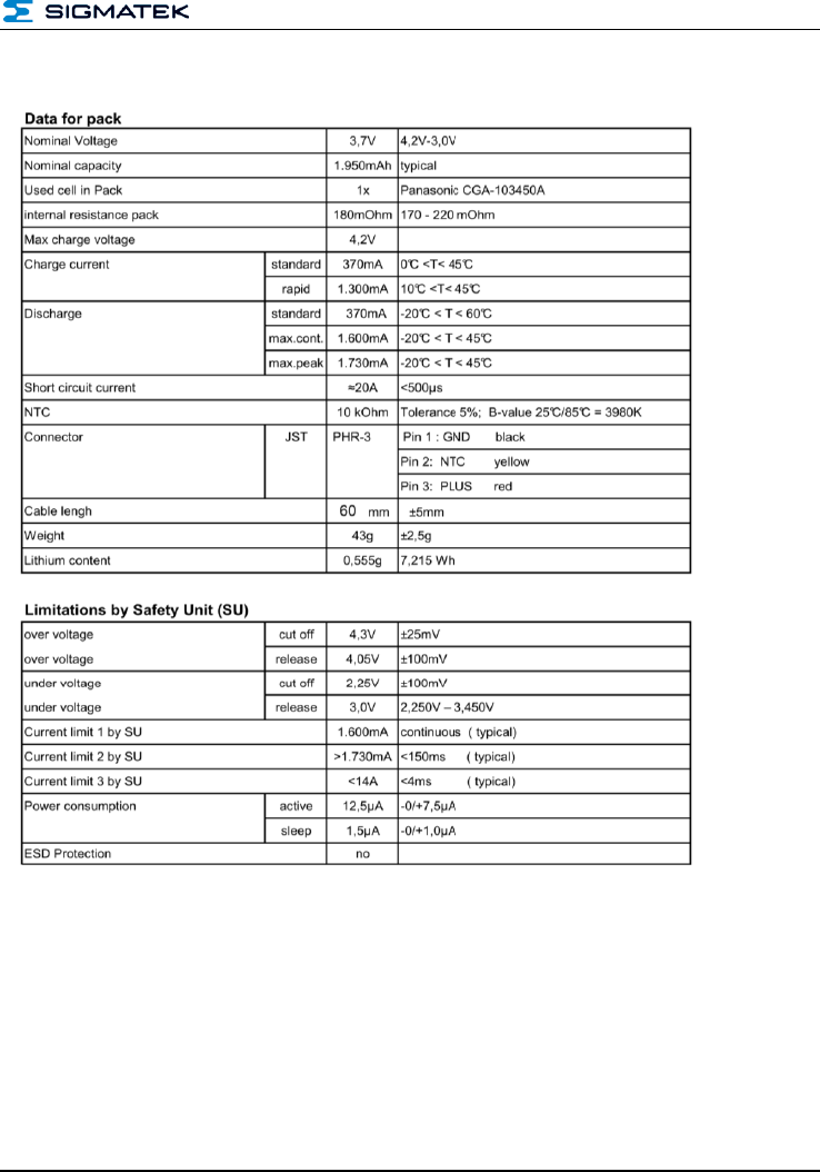
8.1 Battery Data Sheet
MS 021 SHOE ELECTRONICS
Page 18 PRELIMINARY
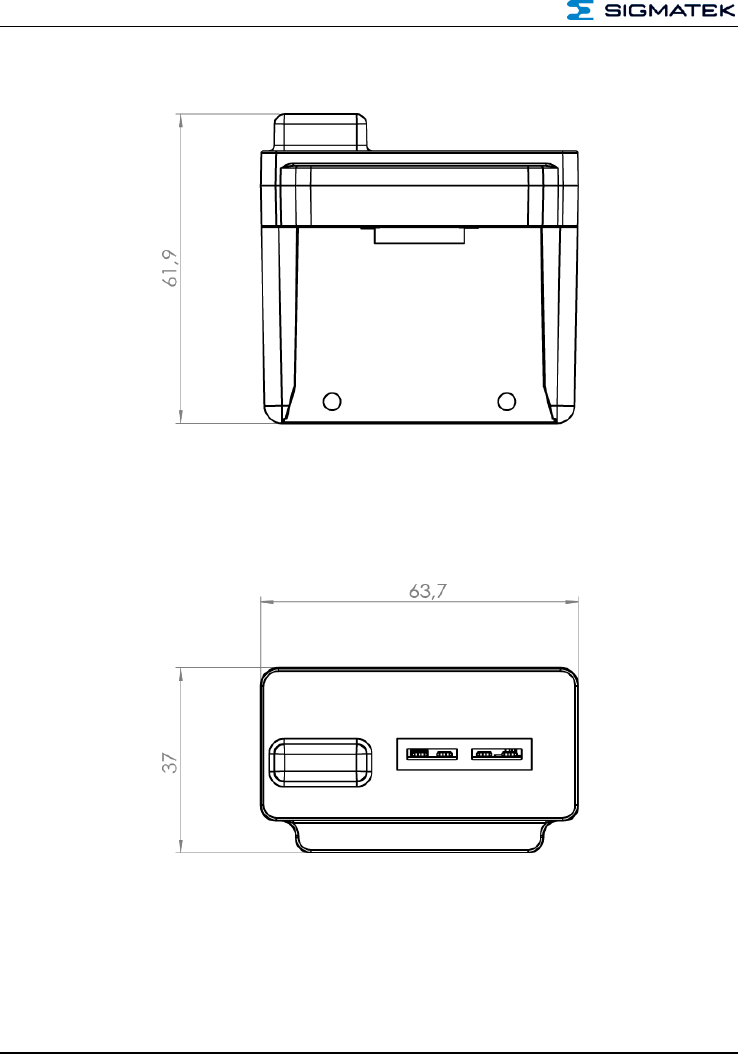
9 Mechanical Dimensions
SHOE ELECTRONICS MS 021
PRELIMINARY Page 19
10 Connector Layout
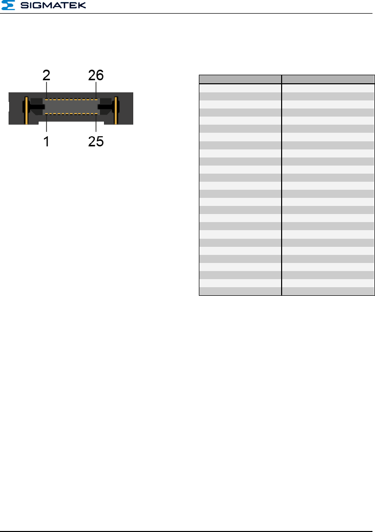
X3: Docking Plug Samtec_ERF8-013-S-D-RA
Pin
Function
1
DC-IN (Charger)
2
DC-IN (Charger)
3
BATT+
4
BATT+
5
GND
6
BATT-NTC
7
3V3
8
GND
9
EEPROM SDA
10
ADXL1_CLK
11
EEPROM SCL
12
ADXL1_SDI
13
ADXL2_CLK
14
ADXL1_SDO
15
ADXL2_SDI
16
ADXL1_/CE
17
ADXL2_SDO
18
XGND
19
ADXL2_/CE
20
Pressure sensor FSR1
21
Pressure sensor XGND
22
Pressure sensor FSR2
23
Vibration +Motor_on
24
Ultrasound GND
25
Vibration motor GND
26
Ultrasound Chirp_EXT
MS 021 SHOE ELECTRONICS
Page 20 PRELIMINARY
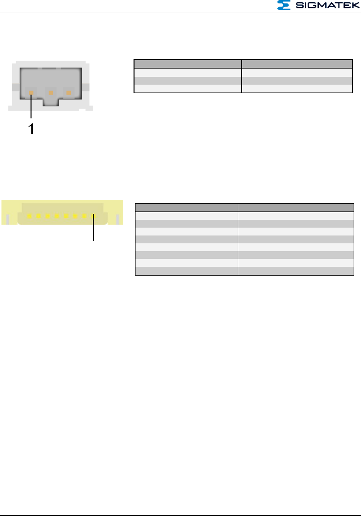
X1: Battery Connector JST S3B-PH-SM4-TB
J1, J2: JTAG Programming Connector (Internal)
Pin
Function
1
GND
2
BATT-NTC
3
BATT+
Pin
Function
1
TDI
2
TMS
3
TCK
4
/TRST
5
TDO
6
/uC-Reset
7
+3.3 V
8
GND
1

SHOE ELECTRONICS MS 021
PRELIMINARY Page 21
11 FCC Statement
FCC ID: 2ACQNAMM002
This device complies with Part 15 of the FCC rules. Operation is subject to the following two
conditions: (1) This device may not cause harmful interference, and (2) this device must
accept any interference received, including interference that may cause undesired opera-
tion.
Section 15.21 Information to user
Changes or modifications not expressly approved by the party responsible for compliance
could void the user's authority to operate the equipment.
Section 15.105 (b)
Note: This equipment has been tested and found to comply with the Limits for a Class B
digital device, pursuant to part 15 of the FCC Rules. These limits are designed to provide
reasonable protection against harmful interference in a residential installation. This equip-
ment generates, uses and can radiate radio frequency energy and, if not installed and used
in accordance with the instructions, may cause harmful interference to radio communica-
tions. However, there is no guarantee that interference will not occur in a particular installa-
tion.
If this equipment does cause harmful interference to radio or television Reception, which
can be determined by turning the equipment off and on, the user is encouraged to try to
correct the interference by one or more of the following measures:
Reorient or relocate the receiving antenna.
Increase the separation between the equipment and receiver.
Connect the equipment into an outlet on a circuit different from that to which the re-
ceiver is connected.
Consult the dealer or an experienced radio/TV technician for help.

MS 021 SHOE ELECTRONICS
Page 22 PRELIMINARY
Documentation Changes
Change date
Affected
page(s)
Chapter
Note