Sigmatek and Co KG PHR001 HF-RFID Reader User Manual HF RFID Reader Modul
Sigmatek GmbH & Co KG HF-RFID Reader HF RFID Reader Modul
User Manual

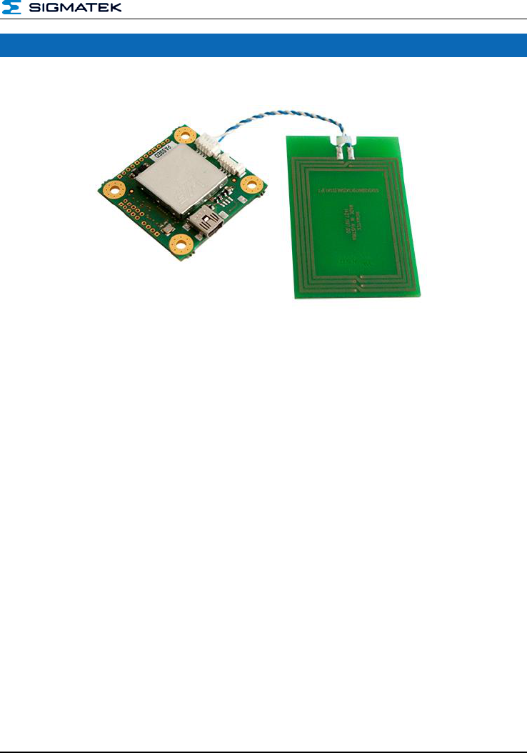
HF-RFID
Reader Module
Date of creation: 23.07.2014
Version date: 28.03.2014
Article number: xxxxxx

Publisher: SIGMATEK GmbH & Co KG
A-5112 Lamprechtshausen
Tel.: 06274/4321
Fax: 06274/4321-18
Email: office@sigmatek.at
WWW.SIGMATEK-AUTOMATION.COM
Copyright © 2014
SIGMATEK GmbH & Co KG
All rights reserved. No part of this work may be reproduced, edited using an electronic system, duplicated or distri-
buted in any form (print, photocopy, microfilm or in any other process) without the express permission.
We reserve the right to make changes in the content without notice. The SIGMATEK GmbH & Co KG is not responsible
for technical or printing errors in the handbook and assumes no responsibility for damages that occur through use of
this handbook.
HF-RFID-READER
PRELIMINARY Page 1
HF-RFID Reader

HF-RFID-READER
Page 2 PRELIMINARY
Contents
1 Technical Data ......................................................................... 7
1.1 RFID Specification ........................................................................ 7
1.2 Electrical Requirements ............................................................... 7
1.3 Environmental Conditions ........................................................... 7
2 Mechanical Dimensions .......................................................... 9
3 Connector Layout .................................................................. 10
3.1.1 Applicable Connectors ...................................................................... 11
4 Protocol Description ............................................................. 12
4.1 Structure Packet ......................................................................... 12
4.2 Example of Communication ...................................................... 13
4.2.1 From Host to RFID Reader ............................................................... 13
4.2.2 From RFID Reader to Host ............................................................... 13
4.3 Breakdown of the Status Bytes ................................................. 13
4.4 Card Types for Protocol Handling ............................................ 14
4.4.1 Protocol ............................................................................................. 14
4.4.2 Card type .......................................................................................... 14
4.5 Checksum .................................................................................... 15
4.5.1 Data Configuration Example ............................................................. 15
5 Overview of the Available Commands ................................ 16
5.1 General Reader Commands ....................................................... 16
5.2 General Transponder Commands ............................................. 16
5.3 Tag-specific Commands ............................................................ 16

HF-RFID-READER
PRELIMINARY Page 3
5.4 DESFire-Commands ................................................................... 17
6 Detailed Description of the Commands .............................. 18
6.1 Get-Reader Name – 0x00 ............................................................ 18
6.1.1 From Host to RFID Reader ............................................................... 18
6.1.2 From RFID Reader to Host ............................................................... 18
6.1.3 Example ............................................................................................ 18
6.2 Get-Product Name – 0x01 .......................................................... 19
6.2.1 From Host to RFID Reader ............................................................... 19
6.2.2 From RFID Reader to Host ............................................................... 19
6.2.3 Example ............................................................................................ 19
6.3 Get-Software Revision – 0x02 ................................................... 20
6.3.1 From Host to RFID Reader ............................................................... 20
6.3.2 From RFID Reader to Host ............................................................... 20
6.3.3 Example ............................................................................................ 20
6.4 Get-Hardware Revision – 0x03 .................................................. 21
6.4.1 From Host to RFID Reader ............................................................... 21
6.4.2 From RFID Reader to Host ............................................................... 21
6.4.3 Example ............................................................................................ 21
6.5 Get-Bootloader Revision – 0x04 ................................................ 22
6.5.1 From Host to RFID Reader ............................................................... 22
6.5.2 From RFID Reader to Host ............................................................... 22
6.5.3 Example ............................................................................................ 22
6.6 Calibrate Antenna – 0x05 ........................................................... 23
6.6.1 From Host to RFID Reader ............................................................... 23
6.6.2 From RFID Reader to Host ............................................................... 23
6.6.3 Example ............................................................................................ 23
6.7 Scan Tags – 0x06 ........................................................................ 24

HF-RFID-READER
Page 4 PRELIMINARY
6.7.1 From Host to RFID Reader ............................................................... 24
6.7.2 From RFID Reader to Host ............................................................... 24
7 Configuration of Card Data................................................... 24
7.1 Example for 1 Card ..................................................................... 25
7.2 Example for 2 Cards ................................................................... 25
7.3 Select Tag – 0x07 ........................................................................ 27
7.3.1 From Host to RFID Reader ............................................................... 27
7.3.2 From RFID Reader to Host ............................................................... 27
7.3.3 Example ............................................................................................ 28
7.4 DeSelect Tag – 0x08 ................................................................... 29
7.4.1 From Host to RFID Reader ............................................................... 29
7.4.2 From RFID Reader to Host ............................................................... 29
7.5 Read-From Tag – 0x09 ............................................................... 30
7.5.1 Description of Non-encrypted Cards ................................................. 30
7.5.2 From Host to RFID Reader ............................................................... 30
7.5.3 From RFID Reader to Host ............................................................... 30
7.5.4 Example of Reading Non-encrypted Cards: ...................................... 31
7.6 Description of Encrypted Cards ................................................ 32
7.6.1 From Host to RFID Reader ............................................................... 32
7.6.2 From RFID Reader to Host ............................................................... 32
7.6.3 Examples of Reading Encrypted Cards: ........................................... 33
7.7 Write-To Tag – 0x0A ................................................................... 35
7.7.1 Description of Non-encrypted Cards ................................................. 35
7.7.2 From Host to RFID Reader ............................................................... 35
7.7.3 From RFID Reader to Host ............................................................... 35
7.7.4 Example of Writing to Non-encrypted Cards: .................................... 36
7.8 Description of Encrypted Cards ................................................ 37

HF-RFID-READER
PRELIMINARY Page 5
7.8.1 From Host to RFID Reader ............................................................... 37
7.8.2 From RFID Reader to Host ............................................................... 37
7.8.3 Examples of Reading Encrypted Cards: ........................................... 38
7.9 Option Tag Commands – 0x0B .................................................. 39
7.9.1 Commands........................................................................................ 39
7.9.2 From Host to RFID Reader ............................................................... 39
7.9.3 From RFID Reader to Host ............................................................... 40
7.9.4 Example Read AFI – 0x00 ................................................................ 40
7.9.5 Example Write AFI – 0x01 ................................................................ 41
7.9.6 Example LOCK AFI – 0x02 ............................................................... 42
7.9.7 Example READ DSFID – 0x03.......................................................... 42
7.9.8 Example WRITE DSFID – 0x04 ........................................................ 43
7.9.9 Example LOCK DSFID – 0x05 .......................................................... 43
7.9.10 LOCK BLOCK – 0x06 ....................................................................... 44
7.9.11 SYS-INFO – 0x0A ............................................................................. 45
7.10 Get-ATS – 0x0C ........................................................................... 46
7.10.1 From Host to RFID Reader ............................................................... 46
7.10.2 From RFID Reader to Host ............................................................... 46
7.10.3 Example ............................................................................................ 46
7.11 SET-PPS – 0x0D .......................................................................... 47
7.11.1 From Host to RFID Reader ............................................................... 47
7.11.2 From RFID Reader to Host ............................................................... 47
7.11.3 Example ............................................................................................ 47
7.12 Execute Command – 0x0E ......................................................... 48
7.12.1 From Host to RFID Reader ............................................................... 48
7.12.2 From RFID Reader to Host ............................................................... 48
7.12.3 Example ............................................................................................ 49
7.13 SET RSSI – 0x11.......................................................................... 50
7.13.1 From Host to RFID Reader ............................................................... 50

HF-RFID-READER
Page 6 PRELIMINARY
7.13.2 From RFID Reader to Host ............................................................... 50
7.13.3 Example ............................................................................................ 50
8 Communication Process Diagram ....................................... 51
8.1 Connecting with the Reader ...................................................... 51
8.2 With Tag Communication .......................................................... 52
9 Enumerators C ....................................................................... 53
10 Declaration of Conformity .................................................... 55
10.1 FCC Statement ............................................................................ 55
Documentation Changes .............................................................. 56
HF-RFID-READER
PRELIMINARY Page 7
1 Technical Data
1.1 RFID Specification
Protocol
ISO15693 ISO14443A ISO14443B B3
Supported cards
Mifare Ultralight / Ultralight C
Mifare Classic Mini / 1K / 4K
Mifare Desfire EV1 2K, 4K 8K
Mifare Pro, Plus
ISO15693 NXP ICOD SLI, TI TagIT, standard cards
RF power
100 mW
Operating frequency
13.56 MHz
Reading distance
up to 12 cm
(depending on the tag, antenna and ambient conditions)
Write distance
circa 70 % or the read distance
Host interface
USB CDC (Virtual Serial Port)
Default 57600 Baud
IO pins
3 software controllable GPIO pins
Antenna
external via Molex Pico Blade article No. 0532610471
Driver
Windows
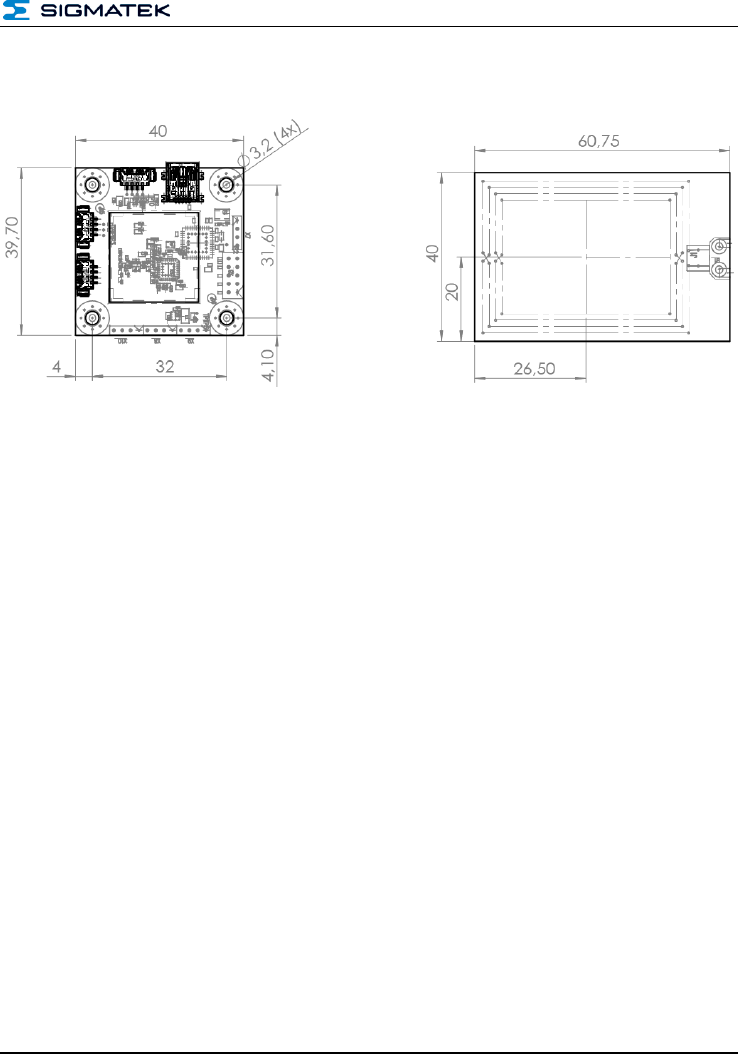
Dimensions
41.00 mm x 37.70 mm x 6.50 mm (W x H x D)
1.2 Electrical Requirements
Supply voltage
5 V DC ±5 % (via USB)
Current consumption
maximum 100 mA
1.3 Environmental Conditions
Storage temperature
-20 ... +85 °C
Operating temperature
0 ... +55 °C
Humidity
0 - 95 %, non-condensing
EMV resistance
in accordance with EN 61000-6-2 (industrial area)
EMC - noise generation
in accordance with EN 61000-6-4 (industrial area)
Radio Communication Conformity
Europe
ETSI EN 302 291
Radio Communication Conformity
USA
FCC CFR 47 Part 15

HF-RFID-READER
Page 8 PRELIMINARY
Product safety
EN 60950-1:2006
HF-RFID-READER
PRELIMINARY Page 9
2 Mechanical Dimensions
HF-RFID-READER
Page 10 PRELIMINARY
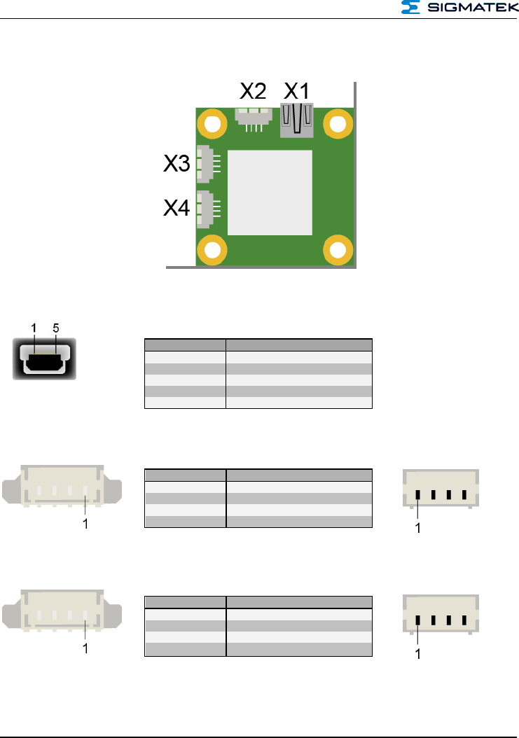
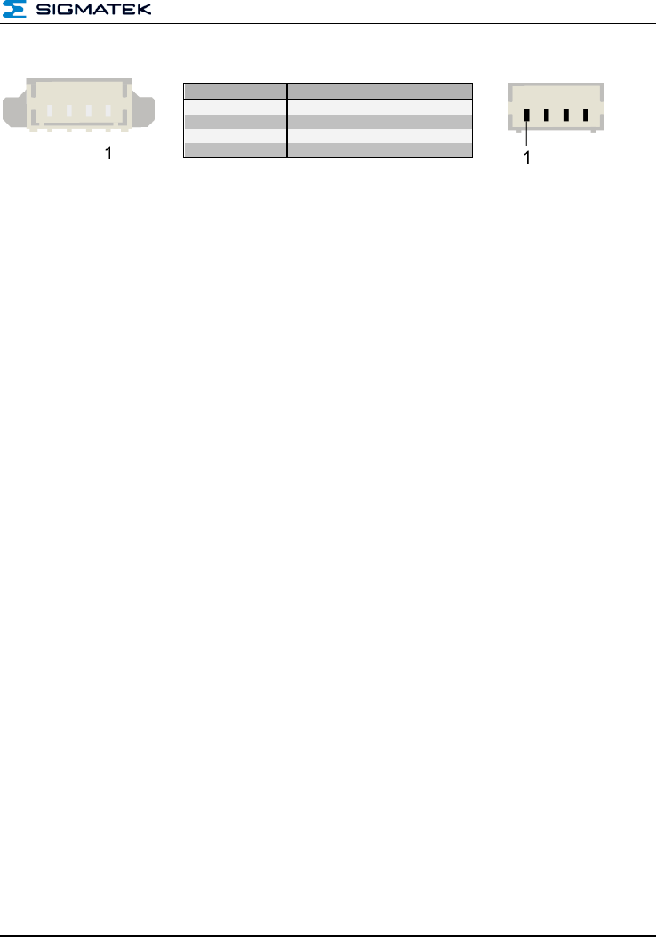
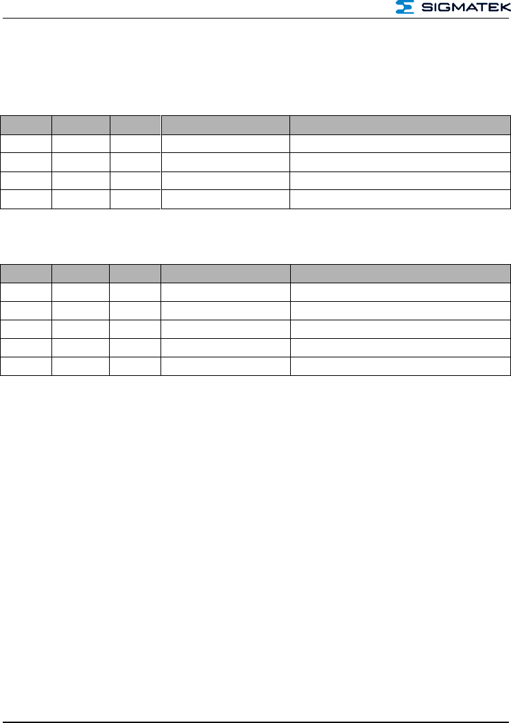
3 Connector Layout
X1: USB-Device 2.0 (Type Mini-B)
X2: USB Device 2.0 (4-pin Molex Pico Blade)
X3: UART (4-pin Molex Pico Blade)
Pin
Function
1
+5 V
2
D-
3
D+
4
n.c.
5
GND
Pin
Function
1
GND
2
D+
3
D-
4
+5 V
Pin
Function
1
+5 V
2
TXD
3
RXD
4
GND
HF-RFID-READER
PRELIMINARY Page 11
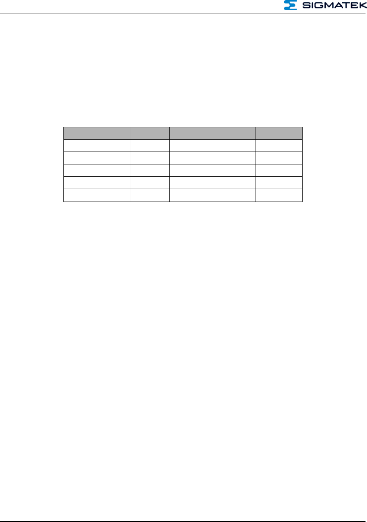
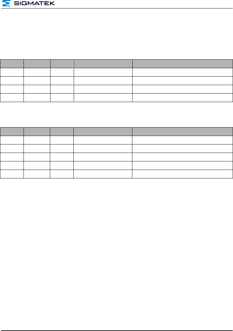
X4: Antenna (4-pin Molex Pico Blade)
3.1.1 Applicable Connectors
X1: USB 2.0 (Type A) (not included in delivery)
X2: 4-pin Molex Pico Blade - 51021-0400
X3: 4-pin Molex Pico Blade - 51021-0400
X4: 4-pin Molex Pico Blade - 51021-0400
Pin
Function
1
RFO 2
2
GND
3
GND
4
RFO 1
HF-RFID-READER
Page 12 PRELIMINARY
4 Protocol Description
The protocol is always the same and independent of the interface used.
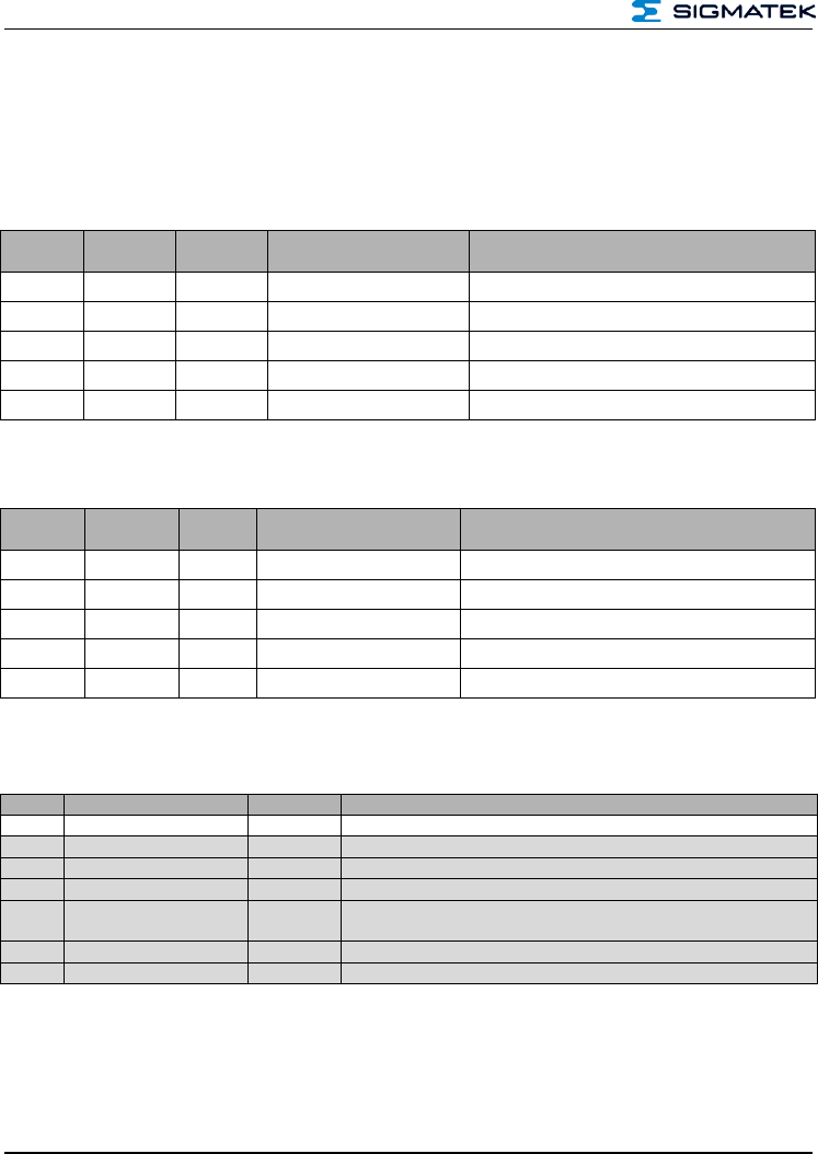
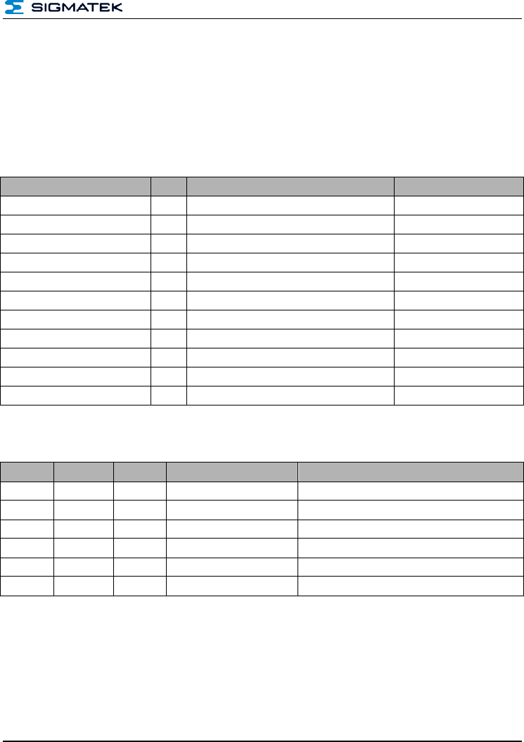
4.1 Structure Packet
All packets between the reader and host have the same structure and must be interpreted
the same.
Description
Number
Short description
Color
Instruction
1 byte
CMD
Blue
status
1 byte
STC
red
Data length
2 bytes
DLI
Orange
DATA
variable
Data
green
Checksum
1 byte
CS
Black
Instruction The field command describes which command should be run. This is described
in chapter 5.
Status: This byte is always 0x00 for commands from the host to the RFIE reader. The
status is used exclusively as a return value for the reader and indexes the status of the
currently executed commands.
Data Length: The "Data length" indicates how much payload data is transferred after this
byte.
Data: The payload data to evaluate.
Checksum: The checksum is used to verify the transferred data. More information can be
found in chapter 4.4.
HF-RFID-READER
PRELIMINARY Page 13
4.2 Example of Communication
As an example, the command 0x02 – Get Software-Revision is used here.
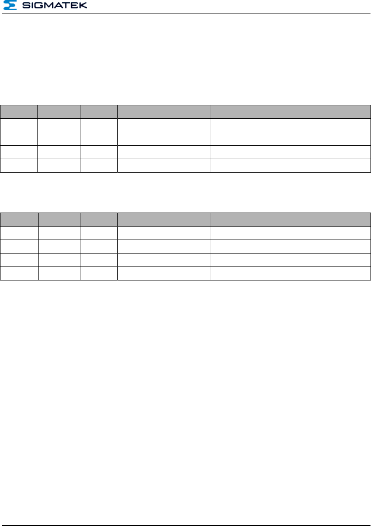
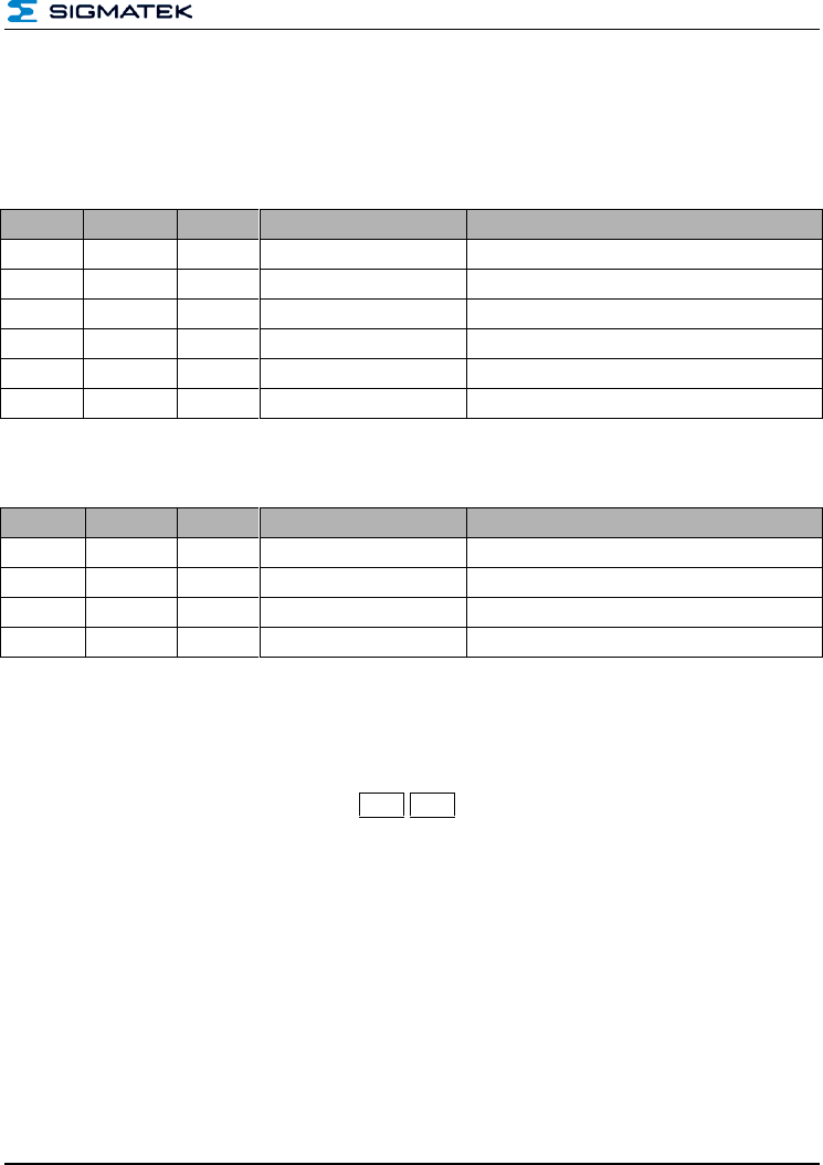
4.2.1 From Host to RFID Reader
Byte
No.
Number
Contents
Data Sent
Value
Description
0
1 byte
CMD
0x02
Command 0x02 "Get Software Revision"
1
1 byte
STC
0x00
Status code for read always 0x00
2 – 3
2 bytes
DLI
0x00, 0x00
Data length
4
1 byte
CS
0x02
Data checksum
4.2.2 From RFID Reader to Host
Byte
No.
Number
Contents
Data Sent
Description
0
1 byte
CMD
0x02
Command 0x02 "Get Software Revision"
1
1 byte
STC
0x00
status code from the host to the reader
2 – 3
2 bytes
DLI
0x00, 0x00
Data length
4 – 7
4 bytes
Data
0x00, 0x01, 0x00, 0x06
Software Revision 01.06
8
1 byte
CS
0x3D
Checksum
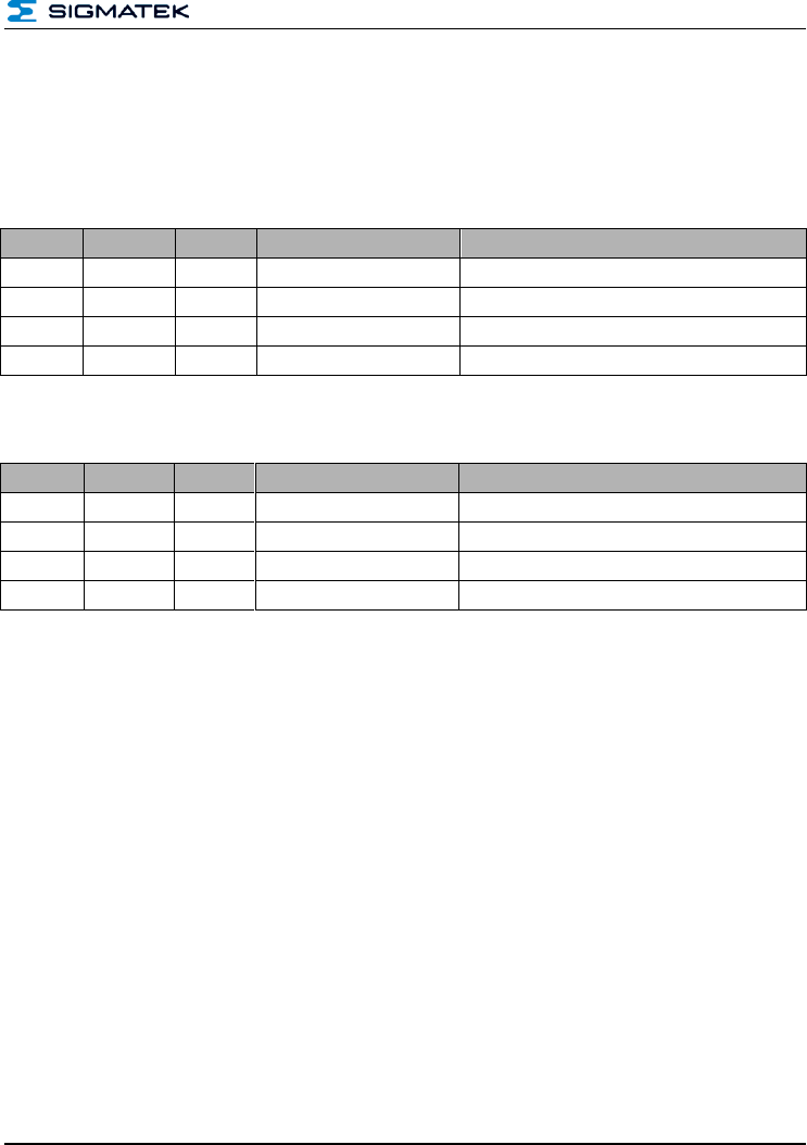
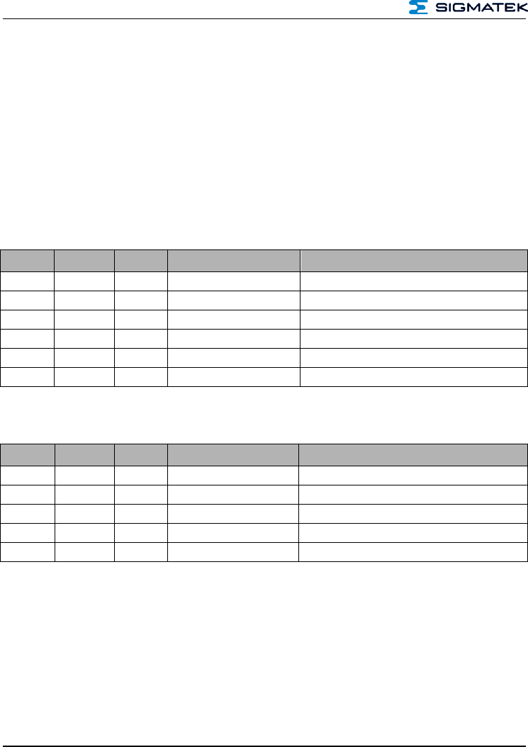
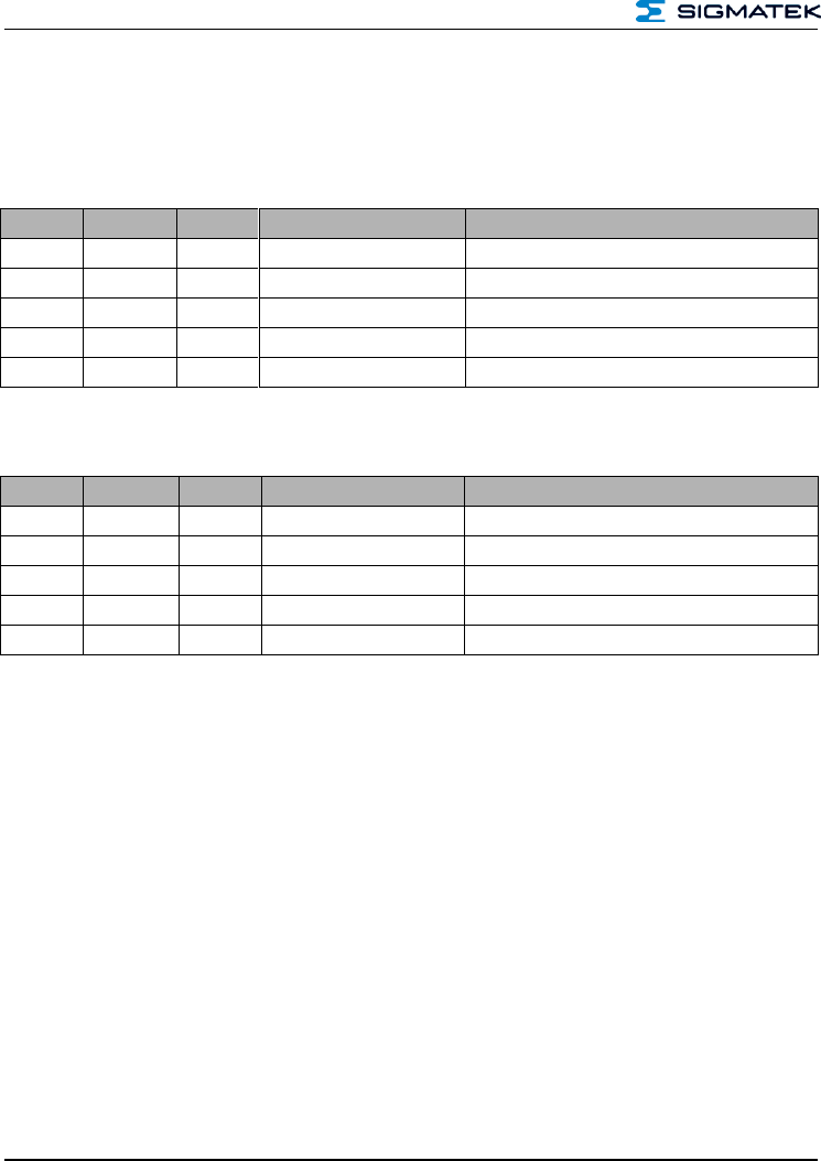
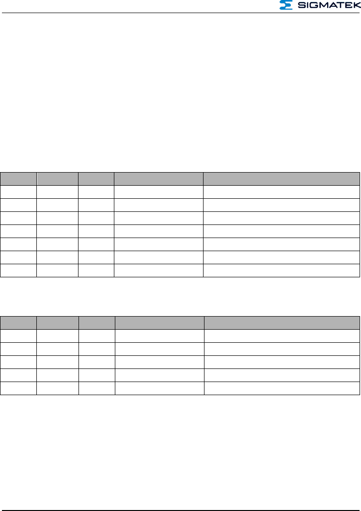
4.3 Breakdown of the Status Bytes
Here, the status bytes and there meanings are explained.
Name
Value
Description
ERR_RET_SUCCESS
0x00
The command was successfully executed
ERR_ET_PARM
0x01
The wrong parameter was sent
ERR_RET_DATA_PUSH
0x02
The wrong data were sent
ERR_RET_CMD_INVALID
0x03
The command used does not exist
ERR_RET_CRC_ERR
0x04
The Checksum is defective
ERR_RET_LENGTH
0x05
The wrong data length was entered
ERR_RET_CMD_DATA
0x06
The data length and transmitted data do not match
ERR_RET_CALIBRATE_ANT
0x0F
The antenna could not be calibrated
ERR_RET_TIMEOUT
0x10
A time out event has occurred
ERR_RET_FIFO_DATA
0x11
No data in FIFO
ERR_RET_COLLISION
0x12
Card collision
ERR_RET_EXEC_CMD
0x13
Error while executing a command
HF-RFID-READER
Page 14 PRELIMINARY
ERR_RET_CARD_NOT_SUPPORTED
0x14
The RFID card is not supported
ERR_RET_AUTH
0x15
Login with card failed
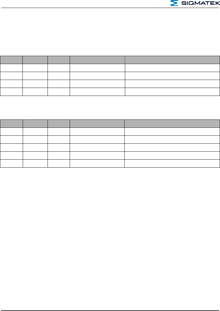
4.4 Card Types for Protocol Handling
4.4.1 Protocol
See Enumerators Table, Chapter 4.6
Norm
Value
Example
Version
ISO14443A
0x00
Mifare Classic 1K
ISO14443B
0x01
NFC Label such as SRI512
ISO15693
0x02
NXP ICode SLI
Unknown card
0xFF
unidentified card
4.4.2 Card type
See Enumerators Table, Chapter 4.6
Card type
Value
Example
Version
Mifare Ultralight
0x00
NXP MF0ICU1
Mifare Mini
0x01
NXP MF1ICS20
Mifare Classic 1K
0x02
NXP MF1S503
Mifare Classic 4K
0x03
NXP MF1S70
Mifare Plus
0x04
MF1 S PLUS60
Mifare DESFire
0x05
MF3 IC D41
Mifare ISO14443A-4
0x06
ISO14443B Srix
0x07
ISO14443B Srix 176
0x08
ISO15693 (default)
0x09
NXP ICode SLI, TI TagIT
Unknown card
0xFF
unidentified card
HF-RFID-READER
PRELIMINARY Page 15
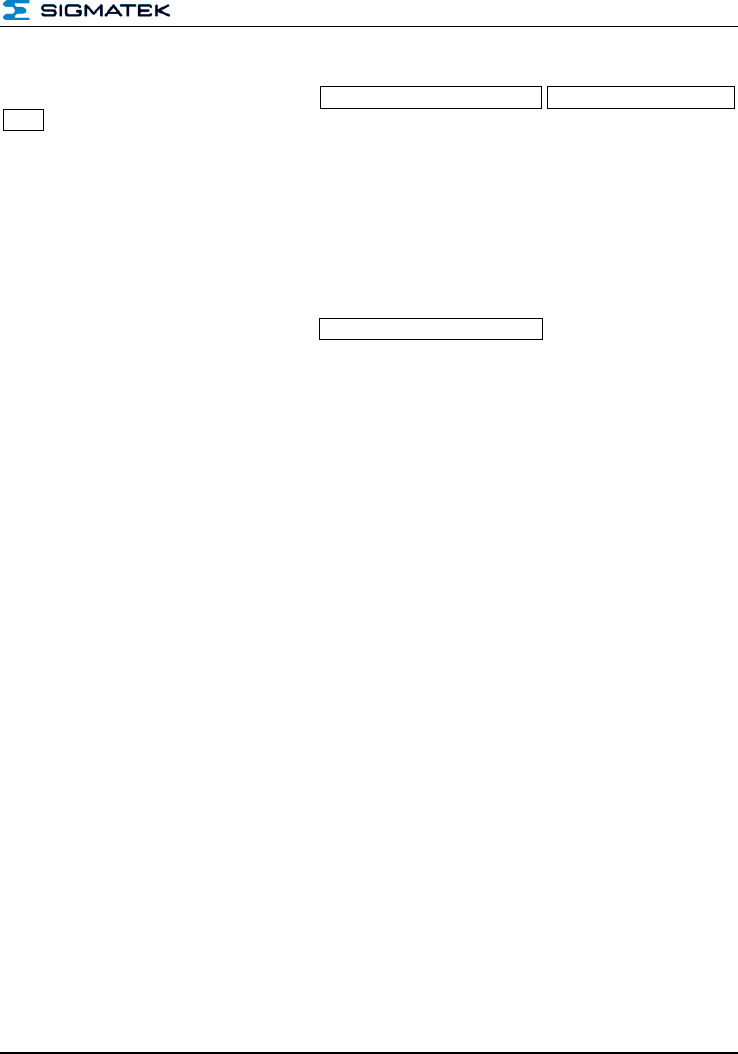
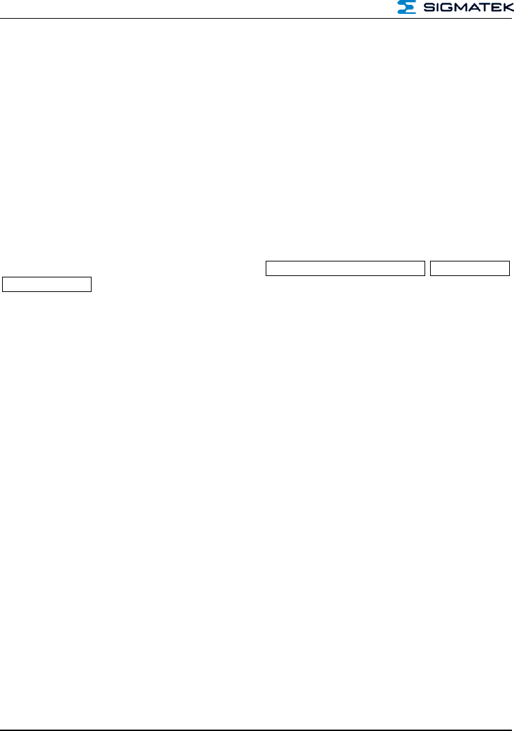
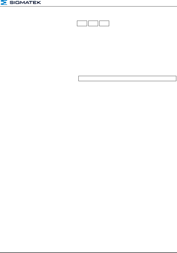
4.5 Checksum
The checksum is an XOR from all bytes. This is calculated as follows:
Example command "Scan Tags – 0x06"
4.5.1 Data Configuration Example
Byte No.
Number
Contents
Data Sent
Description
0
1 byte
CMD
0x06
Command "Scan Tags"
1
1 byte
STC
0x00
Status code for read always 0x00
2 – 3
2 bytes
DLI
0x01, 0x00
Data length
4
1 byte
Data
0x00
Card type
5
1 byte
CS
0x07
Data checksum
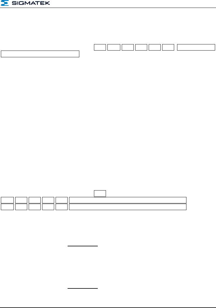
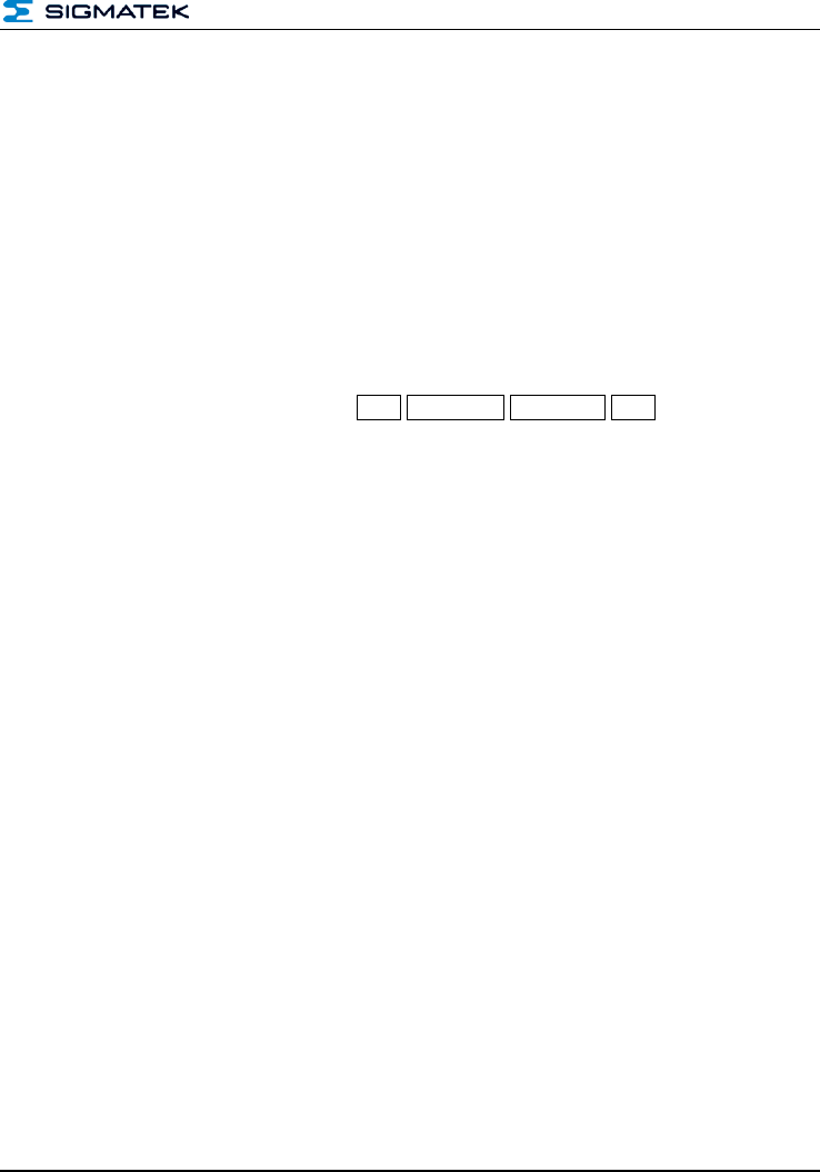
Below the data (0x06 0x00 0x01 0x00 0x02) that should be sent to the reader can be seen.
Before the data are sent, the checksum (byte 5) must be formed.
The checksum in an XOR or each subsequent byte.
Bytes
Number
0x06 0x00 0x01 0x00 0x02
data to send (command, status...)
0x06 ⊻ 0x00 ⊻ 0x01 ⊻ 0x00 ⊻ 0x02
XOR calculation
0x05
Checksum
0x06 0x00 0x01 0x00 0x02 0x05
data to send including the checksum
⊻ = XOR
HF-RFID-READER
Page 16 PRELIMINARY
5 Overview of the Available Commands
5.1 General Reader Commands
Instruction
Value
Description
Version
GET-Reader Name
0x00
Calls the reader name
GET-Product Name
0x01
Calls the product name
GET-Software Rev.
0x02
Calls the software version
GET-Hardware Rev.
0x03
Calls the hardware version
GET-Bootloader Rev.
0x04
Calls the booloader version
Calibrate_Antenna
0x05
Calibrates the antenna
GET-Feature
0x10
Calls the available functions
SET-RSSI
0x11
Activates the RSSI value transition
GPIO_Commands
0x0F
Enables the control of GPIOs
5.2 General Transponder Commands
General commands that can be used in all tags.
Instruction
Value
Description
Version
Scan_Tags
0x06
Searches for tags that are in range.
Select_Tag
0x07
Selects a tag
Deslect_Tag
0x08
Deselects a tag
Read_From_Tag
0x09
Reads data from a tag
Write_To_Tag
0x0A
Writes data to a tag
5.3 Tag-specific Commands
The tag-specific commands are limited to a tag group or type.
Instruction
Value
Description
Version
Option_Tag
0x0B
See chapter 7.9 (ISO15693 only)

HF-RFID-READER
PRELIMINARY Page 17
5.4 DESFire-Commands
This command is used with Mifare DESFire cards. More information can be found in the
DESFire standards documentation.
Please reference the NXP documentation for the DESFire standard
Instruction
Value
Description
Version
Get ATS
0x0C
Call answer from the card for select
Set PPC
0x0D
Sets communication parameters
Execute Command
0x0E
Executes a command on a DESFire card
HF-RFID-READER
Page 18 PRELIMINARY
6 Detailed Description of the Commands
6.1 Get-Reader Name – 0x00
The command returns the reader name.
6.1.1 From Host to RFID Reader
Byte No.
Number
Contents
Data Sent
Description
0
1 byte
CMD
0x00
Command "Get-Reader Name"
1
1 byte
STC
0x00
Status code for read always 0x00
2 – 3
2 bytes
DLI
0x00, 0x00
Data length
4
1 byte
CS
0x00
Data checksum
6.1.2 From RFID Reader to Host
Byte No.
Number
Contents
Data Sent
Description
0
1 byte
CMD
0x00
Command "Get-Reader Name"
1
1 byte
STC
0x00
status code from reader, see chapter 4.3
2 – 3
2 bytes
DLI
0x00, 0x00
Data length
x
x byte
Data
0xFF, 0xFF, 0xFF
Reader name as ASCII string
X + 1
1 byte
CS
0x3D
Checksum
6.1.3 Example
Host to Reader: 0x00 0x00 0x00 0x00 0x00
Reader to Host: 0x00 0x00 0x05 0x00 0x52 0x2D 0x4F 0x45 0x4D 0x3D
Command = 0x00 => Command "Get-Reader Name"
Status = 0x00 => action error-free
Data length = 0x05 0x00 => 5 bytes
Data = 0x52 0x2D 0x4F 0x45 0x4D => ASCII „R-OEM“
Checksum = 0x3D
Sent: 5 bytes
Received: 10 bytes
HF-RFID-READER
PRELIMINARY Page 19
6.2 Get-Product Name – 0x01
The command returns the product name of the reader.
6.2.1 From Host to RFID Reader
Byte No.
Number
Contents
Data Sent
Description
0
1 byte
CMD
0x01
Command "Get-Product Name"
1
1 byte
STC
0x00
Status code for read always 0x00
2 – 3
2 bytes
DLI
0x00, 0x00
Data length
4
1 byte
CS
0x01
Data checksum
6.2.2 From RFID Reader to Host
Byte No.
Number
Contents
Data Sent
Description
0
1 byte
CMD
0x01
Command "Get-Product Name"
1
1 byte
STC
0x00
status code from reader, see chapter 4.3
2 – 3
2 bytes
DLI
0x00, 0x00
Data length
x
x byte
Data
0xFF, 0xFF, 0xFF
Product name as ASCII string
X + 1
1 byte
CS
0x3D
Checksum
6.2.3 Example
Host to Reader: 0x01 0x00 0x00 0x00 0x01
Reader to Host: 0x01 0x00 0x0D 0x00 data: 0x39 0x30 0x30 0x2D 0x4D 0x54 0x2D 0x53
0x65 0x72 0x69 0x61 0x6C 0x0C
Command = 0x01 => Command "Get-Product Name"
Status = 0x00 => action error-free
Data length = 0x0D 0x00=> 13 bytes
Data = data => ASCII String "900-MT-Serial"
Checksum = 0x0C
Sent: 5 bytes
Received: 18 bytes
HF-RFID-READER
Page 20 PRELIMINARY
6.3 Get-Software Revision – 0x02
The command returns the name of the software version found on the reader.
6.3.1 From Host to RFID Reader
Byte No.
Number
Contents
Data Sent
Description
0
1 byte
CMD
0x02
Command "Get-Software Revision"
1
1 byte
STC
0x00
Status code for read always 0x00
2 – 3
2 bytes
DLI
0x00, 0x00
Data length
4
1 byte
CS
0x02
Data checksum
6.3.2 From RFID Reader to Host
Byte No.
Number
Contents
Data Sent
Description
0
1 byte
CMD
0x02
Command "Get-Software Revision"
1
1 byte
STC
0x00
status code from reader, see chapter 4.3
2 – 3
2 bytes
DLI
0x04, 0x00
Data length
4 – 7
4 bytes
Data
0x00, 0x02, 0x00, 0x09
Software version (02.09)
8
1 byte
CS
0x0D
Checksum
6.3.3 Example
Host to Reader: 0x02 0x00 0x00 0x00 0x02
Reader to Host: 0x02 0x00 0x04 0x00 0x00 0x02 0x00 0x09 0x0D
Command = 0x02 => Command "Get-Software Revision"
Status = 0x00 => action error-free
Data length = 0x0D 0x00 => 4 bytes
Data = 0x00 0x02 0x00 0x09 => Software Revision 02.09
Checksum = 0x0D
Sent: 5 bytes
Received: 9 bytes
HF-RFID-READER
PRELIMINARY Page 21
6.4 Get-Hardware Revision – 0x03
The command returns the hardware version of the reader.
6.4.1 From Host to RFID Reader
Byte No.
Number
Contents
Data Sent
Description
0
1 byte
CMD
0x03
Command "Get-Hardware Revision"
1
1 byte
STC
0x00
Status code for read always 0x00
2 – 3
2 bytes
DLI
0x00, 0x00
Data length
4
1 byte
CS
0x03
Data checksum
6.4.2 From RFID Reader to Host
Byte No.
Number
Contents
Data Sent
Description
0
1 byte
CMD
0x03
Command "Get-Hardware Revision"
1
1 byte
STC
0x00
status code from reader, see chapter 4.3
2 – 3
2 bytes
DLI
0x04, 0x00
Data length
4 – 7
4 bytes
Data
0x00, 0x01, 0x00, 0x00
Hardware version (01.00)
8
1 byte
CS
0x06
Checksum
6.4.3 Example
Host to Reader: 0x03 0x00 0x00 0x00 0x03
Reader to Host: 0x03 0x00 0x04 0x00 0x00 0x01 0x00 0x00 0x06
Command = 0x03 => Command "Get-Hardware Revision"
Status = 0x00 => action error-free
Data length = 0x04 0x00 => 4 bytes
Data = 0x00 0x01 0x00 0x00 => Hardware Revision 01.00
Checksum = 0x06
Sent: 5 bytes
Received: 9 bytes
HF-RFID-READER
Page 22 PRELIMINARY
6.5 Get-Bootloader Revision – 0x04
The command returns the bootloader revision on the reader.
6.5.1 From Host to RFID Reader
Byte No.
Number
Contents
Data Sent
Description
0
1 byte
CMD
0x04
Command "Get-Bootloader Revision"
1
1 byte
STC
0x00
Status code for read always 0x00
2 – 3
2 bytes
DLI
0x00, 0x00
Data length
4
1 byte
CS
0x04
Data checksum
6.5.2 From RFID Reader to Host
Byte No.
Number
Contents
Data Sent
Description
0
1 byte
CMD
0x04
Command "Get-Bootloader Revision"
1
1 byte
STC
0x00
Status code from reader, see chapter 4.3
2 – 3
2 bytes
DLI
0x04, 0x00
Data length
4 – 7
4 bytes
Data
0x00, 0x01, 0x00, 0x00
Bootloader version (01.00)
8
1 byte
CS
0x01
Checksum
6.5.3 Example
Host to Reader: 0x04 0x00 0x00 0x00 0x04
Reader to Host: 0x04 0x00 0x04 0x00 0x00 0x01 0x00 0x00 0x01
Command = 0x04 => Command "Get-BootloaderRevision"
Status = 0x00 => action error-free
Data length = 0x04 0x00 => 4 bytes
Data = 0x00 0x01 0x00 0x00 => Bootloader Revision 01.00
Checksum = 0x01
Sent: 5 bytes
Received: 9 bytes
HF-RFID-READER
PRELIMINARY Page 23
6.6 Calibrate Antenna – 0x05
Calibrates the antenna within the range of the system limits. If the calibration fails, a specific
error code is returned.
6.6.1 From Host to RFID Reader
Byte No.
Number
Contents
Data Sent
Description
0
1 byte
CMD
0x05
Command "Calibrate Antenna"
1
1 byte
STC
0x00
Status code for read always 0x00
2 – 3
2 bytes
DLI
0x00, 0x00
Data length
4
1 byte
CS
0x05
Data checksum
6.6.2 From RFID Reader to Host
Byte No.
Number
Contents
Data Sent
Description
0
1 byte
CMD
0x05
Command "Calibrate Antenna"
1
1 byte
STC
0x00
Status code from reader, see chapter 4.3
2 – 3
2 bytes
DLI
0x00, 0x00
Data length
4
1 byte
CS
0x05
Checksum
6.6.3 Example
Host to Reader: 0x05 0x00 0x00 0x00 0x05
Reader to Host: 0x05 0x00 0x00 0x00 0x05
Command = 0x05 => Command "Calibrate Antenna"
Status = 0x00 => action error-free
Data length = 0x00 0x00 => 4 bytes
Checksum = 0x05
Sent: 5 bytes
Received: 9 bytes
HF-RFID-READER
Page 24 PRELIMINARY
6.7 Scan Tags – 0x06
With the Scan Tags command, all available tags with the reading range of the RFID reader
listed.
6.7.1 From Host to RFID Reader
Byte
No.
Number
Contents
Data Sent
Description
0
1 byte
CMD
0x06
command "Scan Tags"
1
1 byte
STC
0x00
Status code for read always 0x00
2 – 3
2 bytes
DLI
0x01, 0x00
Data length
4
1 byte
Data
0x00
Card type, see chapter 4.4.2!
5
1 byte
CS
0x07
Data checksum
6.7.2 From RFID Reader to Host
Byte
No.
Number
Con-
tents
Data Sent
Description
0
1 byte
CMD
0x06
Command "Scan Tags"
1
1 byte
STC
0x00
Status code from reader, see chapter 4.3
2 – 3
2 bytes
DLI
0xFF, 0xFF
Data length
x
x byte
Data
0xFF, 0xFF, 0xFF 0xFF
Card information
x +1
1 byte
CS
0xFF
Checksum
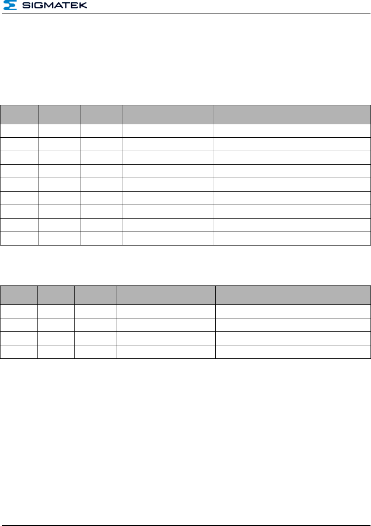
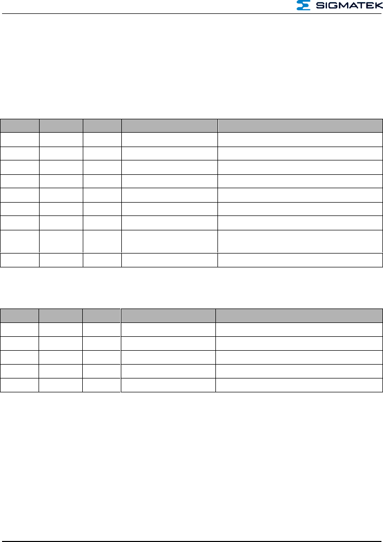
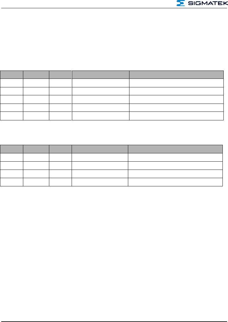
7 Configuration of Card Data
Block
Name
Description
0
Number of tags
1 byte
Returns the number of tags found
1
Card data length
1 byte
Returns the number of bytes contained in the card data.
2
Card type
1 byte
Indicates the card type, e.g. 0x02 = ISO15693
3
Card subtype
1 byte
Indicates the exact type of card 0x09 = ISO15693 standard
4
RSSI value
1 byte
Indicates the RSSI value of the card (receiver field
strength)
5
UID length
1 byte
Indicates the UID length as follows
6
UID
X bytes
The UID
The fields marked in grey repeat for each recognized RFID card.
RSSI value: The RSSI value represents the Receiver field data
HF-RFID-READER
PRELIMINARY Page 25
7.1 Example for 1 Card
Host to Reader: 0x06 0x00 0x01 0x00 0x02 0x07
Reader to Host: 0x06 0x00 0x0E 0x00 0x01 0x0D 0x02 0x09 0x50 0x08 UID:0xEA 0xAA
0xD9 0x7F 0x00 0x01 0x04 0xE0 0x54
Command = 0x06 => Command "Scan Tags"
Status = 0x00 => action error-free
Data length = 0x0E 0x00=> 14 bytes
Data = 0x01 => number of cards found
0x0D => card data length 12 bytes
0x02 => card type ISO15693
0x09 => Cards SubType ISO15693 Standard
0x50 => RSSI (If not activated, the value is 0x00)
0x08 => UID length 8 bytes
UID => EA-AA-D9-7F-00-01-04-E0
Checksum = 0x54
Sent: 6 bytes
Received: 19 bytes
7.2 Example for 2 Cards
Host to Reader: 0x06 0x00 0x01 0x00 0x02 0x07
Reader to Host: 0x06 0x00 0x1B 0x00 0x02
0x0D 0x02 0x09 0x94 0x08 UID:0x50 0x72 0xD9 0x7F 0x00 0x01 0x04 0xE0
0x0D 0x02 0x09 0x84 0x08 UID:0xEA 0xAA 0xAD 0x97 0xF0 0x01 0x04 0xE0 0x6D
Command = 0x06 => Command "Scan Tags"
Status = 0x00 => action error-free
Data length = 0x1B 0x00=> 27 bytes
Dat = 0x02 => number of cards found 2
Data card 1:
0x0D => card data length 12 bytes
0x02 => card type ISO15693
0x09 => Cards SubType ISO15693 Standard
0x50 => RSSI (If not activated, the value is 0x00)
0x08 => UID length (8 bytes)
UID => EA-AA-D9-7F-00-01-04-E0
Data card 2:
0x0D => card data length 12 bytes
0x02 => card type ISO15693

HF-RFID-READER
Page 26 PRELIMINARY
0x09 => Cards SubType ISO15693 Standard
0x84 => RSSI (If not activated, the value is 0x00)
0x08 => UID length (8 bytes)
UID => EA-AA-D9-7F-00-01-04-E0
Checksum = 0x6D
HF-RFID-READER
PRELIMINARY Page 27
7.3 Select Tag – 0x07
This command selects the card for further operations such as read or write. As soon as a
tag is selected, the HF field is active and communication with the card can be established.
7.3.1 From Host to RFID Reader
Byte
No.
Number
Contents
Data Sent
Description
0
1 byte
CMD
0x07
Command "Select Tag"
1
1 byte
STC
0x00
Status code for read always 0x00
2 – 3
2 bytes
DLI
0x00, 0x00
Data length
4
1 byte
Data
0x00
Length of the card data
5
1 byte
Data
0x00
Card type
6
1 byte
Data
0x00
Card subtype
7
1 byte
Data
0x00
Dummy byte with content 0x00
8 –x
Variable
Data
0x00, 0x00, 0x00, 0x00
UID of the card to select
x +1
1 byte
CS
0x00
Checksum
7.3.2 From RFID Reader to Host
Byte
No.
Number
Contents
Data Sent
Description
0
1 byte
CMD
0x07
Command "Select Tag"
1
1 byte
STC
0x00
Status code from reader, see chapter 4.3
2 – 3
2 bytes
DLI
0x00, 0x00
Data length
4
1 byte
CS
0x07
Checksum
HF-RFID-READER
Page 28 PRELIMINARY
7.3.3 Example
Host to Reader: 0x070x00 0x0D 0x00 0x0D 0x02 0x09 0x00 0x08 UID: 0xD5 0x4C 0xD8
0x7F 0x00 0x01 0x04 0xE0 0xDF
Command = 0x07 => Command "Select Tag"
Status = 0x00 => dummy byte 0x00
Data length = 0x0D 0x00=> 14 bytes
Data = 0x0D => card data length 12 bytes
0x02 => card type ISO15693
0x09 => Cards SubType ISO15693 Standard
0x00 => dummy byte with 0x00
0x08 => UID length 8 bytes
UID => D5-4C-D8-7F-00-01-04-E0
Checksum = 0xDF
Reader to Host: 0x07 0x00 0x00 0x00 0x07 = card selected successfully
HF-RFID-READER
PRELIMINARY Page 29
7.4 DeSelect Tag – 0x08
This command deselects the previously selected card. After running, the HF field is deacti-
vated and communication with the card is ended.
7.4.1 From Host to RFID Reader
Byte No.
Number
Contents
Data Sent
Description
0
1 byte
CMD
0x08
Command "DeSelect Tag"
1
1 byte
STC
0x00
Status code for read always 0x00
2 – 3
2 bytes
DLI
0x00, 0x00
Data length
4
1 byte
CS
0x08
Data checksum
7.4.2 From RFID Reader to Host
Byte No.
Number
Contents
Data Sent
Description
0
1 byte
CMD
0x08
Command "DeSelect Tag"
1
1 byte
STC
0x00
Status code from reader, see chapter 4.3
2 – 3
2 bytes
DLI
0x00, 0x00
Data length
4
1 byte
CS
0x08
Checksum
7.4.2.1 Example
Host to Reader: 0x08 0x00 0x00 0x00 0x08
Reader to Host: 0x08 0x00 0x00 0x00 0x08
Command = 0x08 => Command "DeSelect Tag"
Status = 0x00 => action error-free
Data length = 0x00 0x00 => 0 bytes
Checksum = 0x08
Sent: 5 bytes
Received: 5 bytes
HF-RFID-READER
Page 30 PRELIMINARY
7.5 Read-From Tag – 0x09
With this command, data can be read from the card. Hereby, it must be ensured that the
correct communication variant is selected. This varies between in protocol between "enc-
rypted cards" and "non-encrypted cards"
7.5.1 Description of Non-encrypted Cards
Non-encrypted cards are for example, ISO15693, Mifare Ultralight and others. The descrip-
tion can be found in the card specifications.
7.5.2 From Host to RFID Reader
Byte No.
Number
Contents
Data Sent
Description
0
1 byte
CMD
0x09
Command "Read-From Tag"
1
1 byte
STC
0x00
Status code for read always 0x00
2 – 3
2 bytes
DLI
0x08, 0x00
Data length
4, -7
4 bytes
Data
0x04, 0x00, 0x00, 0x00
Start sector as UINT (here start sector 4)
9 - 10
4 bytes
Data
0x01, 0x00, 0x00, 0x00
Number of sectors (here 1 sector) 1 as UINT
12
1 byte
CS
0x00
Checksum
7.5.3 From RFID Reader to Host
Byte No.
Number
Contents
Data Sent
Description
0
1 byte
CMD
0x07
Command "Read-From Tag"
1
1 byte
STC
0x00
Status code from reader, see chapter 4.3
2 – 3
2 bytes
DLI
0x00, 0x00
Data length
4 - X
Variable
Data
0xFF, 0xFF, 0xFF, 0xFF
the date required from the card
X +1
1 byte
CS
0x07
Checksum
HF-RFID-READER
PRELIMINARY Page 31
7.5.4 Example of Reading Non-encrypted Cards:
Host to Reader: 0x09 0x00 0x08 0x00 Start: 0x04 0x00 0x00 0x00 Count: 0x01 0x00 0x00
0x00 0x04
Command = 0x09=> Command "Read-From Tag"
Status = 0x00 => dummy byte 0x00
Data length = 0x08 0x00 => 8 bytes
Data = Start => start reading data from sector 4
= Count => 1 sector is read
Checksum = 0x04
Reader to Host: 0x09 0x00 0x04 0x00 Data: 0x73 0x69 0x67 0x6D 0x1D
Command = 0x09=> Command "Read-From Tag"
Status = 0x00 => action error-free
Data length = 0x04 0x00 => 4 bytes
Data = Data => 4-byte data
Checksum = 0x04
HF-RFID-READER
Page 32 PRELIMINARY
7.6 Description of Encrypted Cards
With this sequence of the protocol, data is read from cards with encrypted content. Example
of such cards are Mifare 1K or similar. Further information on handling can be found in the
data sheet of the RFID transponder.
7.6.1 From Host to RFID Reader
Byte No.
Number
Contents
Data Sent
Description
0
1 byte
CMD
0x09
Command "Read-From Tag"
1
1 byte
STC
0x00
Status code for read always 0x00
2 – 3
2 bytes
DLI
0x10, 0x00
Data length
4, -7
4 bytes
Data
0x04, 0x00, 0x00, 0x00
Start sector as UINT (here start sector 4)
9 - 10
4 bytes
Data
0x01, 0x00, 0x00, 0x00
Number of sectors (here 1 sector) 1 as UINT
12
1 byte
Data
0x00
KeyType (0x00 = KeyA, 0x01 = KeyB)
13
1 byte
Data
0x06
Length of the keys (here 6 bytes)
14 -19
6 bytes
Data
0xFF, 0xFF, 0xFF, 0xFF,
0xFF, 0xFF
key
20
1 byte
CS
0x1A
Checksum
7.6.2 From RFID Reader to Host
Byte No.
Number
Contents
Data Sent
Description
0
1 byte
CMD
0x07
Command "Read-From Tag"
1
1 byte
STC
0x00
Status code from reader, see chapter 4.3
2 – 3
2 bytes
DLI
0x00, 0x00
Data length
4 - X
Variable
Data
0xFF, 0xFF, 0xFF, 0xFF
the date required from the card
X +1
1 byte
CS
0x07
Checksum

HF-RFID-READER
PRELIMINARY Page 33
7.6.3 Examples of Reading Encrypted Cards:
Host to Reader: 0x09 0x00 0x10 0x00 Start: 0x04 0x00 0x00 0x00 Count: 0x01 0x00 0x00
0x00 0x00 0x06 Key: 0xFF 0xFF 0xFF 0xFF 0xFF 0xFF 0x1A
Command = 0x09=> Command "Read-From Tag"
Status = 0x00 => dummy byte 0x00
Data length = 0x08 0x00 => 8 bytes
Data = Start => start reading data from sector 4
= Count => 1 sector is read
= 0x00 => Key Type (0x00 = KeyA, 0x01 = KeyB)
= 0x06 => Key length 6 bytes
= Key => FF-FF-FF-FF-FF-FF
Checksum = 0x1A
HF-RFID-READER
Page 34 PRELIMINARY
Reader to Host: 0x09 0x00 0x10 0x00 Data: 0x00 0x00 0x00 0x00 0x00 0x00 0x00 0x00
0x00 0x00 0x00 0x00 0x00 0x00 0x00 0x00 0x19
Command = 0x09=> Command "Read-From Tag"
Status = 0x00 => action error-free
Data length = 0x10 0x00=> 16 bytes
Data = Data => 16-byte data
Checksum = 0x04
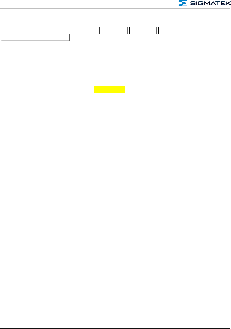
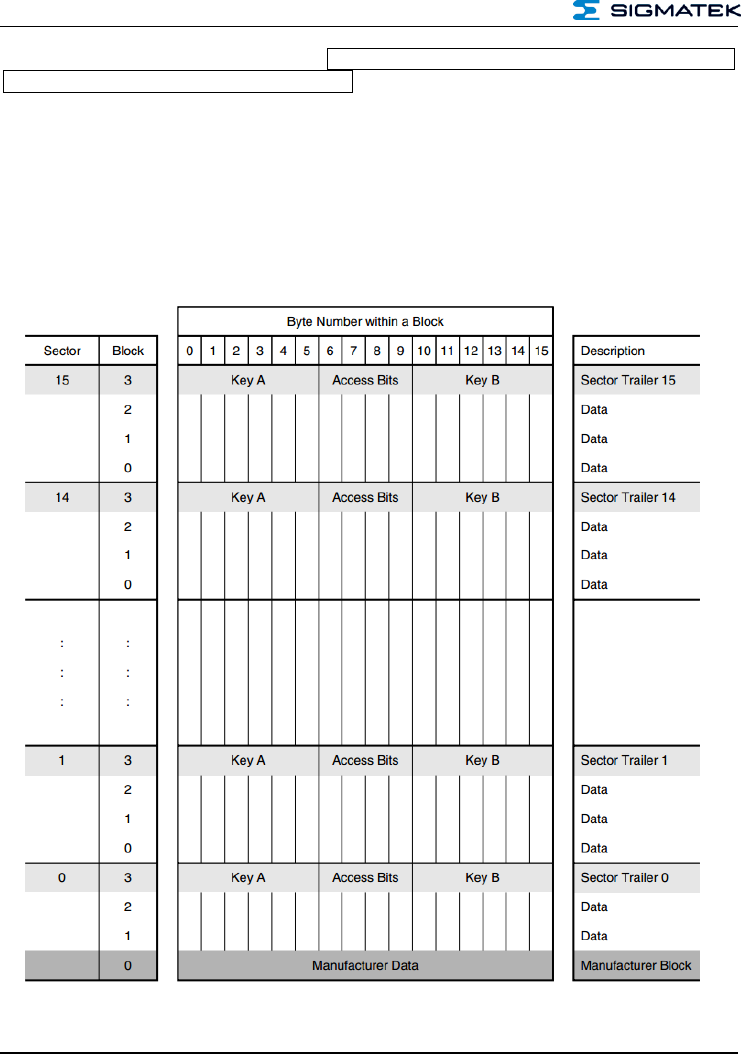
With a Mifare 1K tag, 16 bytes are returned due to the memory organization per sector (4
bytes).
Excerpt from the data sheet for the Mifare 1K Tag MF1S503x from NXP.
HF-RFID-READER
PRELIMINARY Page 35
7.7 Write-To Tag – 0x0A
This instruction writes to the specified areas of the card data. Here, it must be ensured that
the right communication variant is used. This varies between in protocol between "encryp-
ted cards" and "non-encrypted cards"
7.7.1 Description of Non-encrypted Cards
Non-encrypted cards are for example, ISO15693, Mifare Ultralight and others. The descrip-
tion can be found in the card specifications.
7.7.2 From Host to RFID Reader
Byte No.
Number
Contents
Data Sent
Description
0
1 byte
CMD
0x0A
Command "Write-to Tag"
1
1 byte
STC
0x00
Status code for read always 0x00
2 – 3
2 bytes
DLI
0x10, 0x00
Data length
4, -7
4 bytes
Data
0x04, 0x00, 0x00, 0x00
Start sector as UINT (here start sector 4)
9 - 10
4 bytes
Data
0x01, 0x00, 0x00, 0x00
Number of sectors (here 1 sector) 1 as UINT
12 – 15
4 bytes
Data
0x04, 0x00, 0x00, 0x00
Length of the following data as UINT
15 - x
Variable
Data
0x00, 0x01, 0x02, 0x03
Date that should be written
X + 1
1 byte
CS
0x1F
Checksum
7.7.3 From RFID Reader to Host
Byte No.
Number
Contents
Data Sent
Description
0
1 byte
CMD
0x0A
Command "Write-to Tag"
1
1 byte
STC
0x00
Status code from reader, see chapter 4.3
2 – 3
2 bytes
DLI
0x00, 0x00
Data length
4
1 byte
CS
0x0A
Checksum

HF-RFID-READER
Page 36 PRELIMINARY
7.7.4 Example of Writing to Non-encrypted Cards:
Host to Reader: 0x0A 0x00 0x10 0x00 Start: 0x04 0x00 0x00 0x00 Count: 0x01 0x00 0x00
0x00 length: 0x04 0x00 0x00 0x00 Data: 0x01 0x02 0x03 0x04 0x1F
Command = 0x0A=> Command "Write-To Tag"
Status = 0x00 => dummy byte 0x00
Data length = 0x10 0x00=> 16 bytes
Data = Start => start reading data from sector 4
= Count => 1 sector is read
= Data length => 4 bytes are written to the card
= Data => The data that should be written in the tag
Checksum = 0x1F
Reader to Host: 0x0A 0x00 0x00 0x00 0x0A
Command = 0x0A=> Command "Write-To Tag"
Status = 0x00 => action error-free
Data length = 0x00 0x00 => 0 bytes
Checksum = 0x0A
HF-RFID-READER
PRELIMINARY Page 37
7.8 Description of Encrypted Cards
With this sequence of the protocol, data is read from cards with encrypted content. Example
of such cards are Mifare 1K or similar. Further information on handling can be found in the
data sheet of the RFID transponder.
7.8.1 From Host to RFID Reader
Byte No.
Number
Contents
Data Sent
Description
0
1 byte
CMD
0x0A
Command "Write-to Tag"
1
1 byte
STC
0x00
Status code for read always 0x00
2 – 3
2 bytes
DLI
0x29, 0x00
Data length
4, -7
4 bytes
Data
0x04, 0x00, 0x00, 0x00
Start sector as UINT (here start sector 4)
9 - 10
4 bytes
Data
0x01, 0x00, 0x00, 0x00
Number of sectors (here 1 sector) 1 as UINT
4 bytes
Data
0x10, 0x00, 0x00, 0x00
Length of the following data as UINT
16
1 byte
Data
0x00
KeyType (0x00 = KeyA, 0x01 = KeyB)
17
1 byte
Data
0x06
Length of the keys (here 6 bytes)
18 – 23
6 bytes
Data
0xFF, 0xFF, 0xFF, 0xFF,
0xFF, 0xFF
key
23 – X
Variable
Data
0x01, 0x02, 0x03, 0x04
Date that should be written
20
1 byte
CS
0x30
Checksum
7.8.2 From RFID Reader to Host
Byte No.
Number
Contents
Data Sent
Description
0
1 byte
CMD
0x0A
Command "Write-to Tag"
1
1 byte
STC
0x00
Status code from reader, see chapter 4.3
2 – 3
2 bytes
DLI
0x00, 0x00
Data length
4
1 byte
CS
0x0A
Checksum
HF-RFID-READER
Page 38 PRELIMINARY
7.8.3 Examples of Reading Encrypted Cards:
Host to Reader: 0x0A 0x00 0x29 0x00 Start: 0x04 0x00 0x00 0x00 Count: 0x01 0x00 0x00
0x00 length: 0x04 0x00 0x00 0x00 0x00 0x06 Key: 0xFF 0xFF 0xFF 0xFF 0xFF 0xFF
Data: 0x00 0x00 0x00 0x00 0x00 0x00 0x00 0x00 0x00 0x00 0x00 0x00 0x00 0x00 0x00
0x00 0x30
Command = 0x0A=> Command "Write-To Tag"
Status = 0x00 => dummy byte 0x00
Data length = 0x29 0x00 => 8 byte
Data = Start => start reading data from sector 4
= Count => 1 sector is read
= Data length => 16 bytes should be written
= 0x00 => Key Type (0x00 = KeyA, 0x01 = KeyB)
= 0x06 => Key length 6 bytes
= Key => FF-FF-FF-FF-FF-FF
= Data => Data that should be written to the card
Checksum = 0x30
Reader to Host: 0x0A 0x00 0x00 0x00 0x0A
Command = 0x0A=> Command "Write-To Tag"
Status = 0x00 => action error-free
Data length = 0x00 0x00 => 0 bytes
Checksum = 0x0A
HF-RFID-READER
PRELIMINARY Page 39
7.9 Option Tag Commands – 0x0B
Running Option Tags Commands allows ISO15693-specific and special instructions to be
run in the tag.
7.9.1 Commands
The following instructions are available as additional commands:
Instruction
Value
Description
Version
CMD_OPT_READ_AFI
0x00
Returns the value of the AFI register
CMD_OPT_WRITE_AFI
0x01
Writes the AFI
CMD_LOCK_AFI
0x02
Sets the AFI to Read Only
CMD_READ_DSFID
0x03
Returns the value of the DSFID register
CMD_WRITE_DSFID
0x04
Writes the DSFID
CMD_LOCK_DSFID
0x05
Sets the AFI to Read Only
CMD_OPT_LOCK_BLOCK
0x06
Sets a block to Read Only
reserved
0x07
reserved
reserved
0x08
reserved
reserved
0x09
reserved
CMD_SYS_INFO
0x0A
Reads card information
7.9.2 From Host to RFID Reader
Byte No.
Number
Contents
Data Sent
Description
0
1 byte
CMD
0x0B
Command "Option Tag Command"
1
1 byte
STC
0x00
Status code for read always 0x00
2 – 3
2 bytes
DLI
0x00, 0x00
Data length
4
1 byte
OCMD
0x00
Option Tag Command
5 - x
Variable
DATA
0x00 0x00 0x00 0x00
Data / parameters for option commands
x +1
1 byte
CS
0x04
Data checksum
Data are optional and must be implemented depending on the Option Tag Command used.
This is explained in the following examples.

HF-RFID-READER
Page 40 PRELIMINARY
7.9.3 From RFID Reader to Host
Byte No.
Number
Contents
Data Sent
Description
0
1 byte
CMD
0x0B
Command "Option Tag Command"
1
1 byte
STC
0x00
Status code for read always 0x00
2 – 3
2 bytes
DLI
0x00, 0x00
Data length
4 - x
Variable
DATA
0x00 0x00 0x00 0x00
Return data from the card
x +1
1 byte
CS
0x00
Data checksum
Whether data are sent or only a confirmation of the action is explained in this example.
7.9.4 Example Read AFI – 0x00
The AFI register sets the "Application Family identifier" according to ISO15693-3. With this
command, the value of this register is read.
Host to Reader: 0x0B 0x00 0x01 0x00 0x00 0x04
Command = 0x0B => Command "Option Tag Command"
Status = 0x00 => dummy byte 0x00
Data length = 0x01 0x00 => 1 byte
Opt_Command = 0x01 => Read AFI
Checksum = 0x0B
Reader to Host: 0x0B 0x00 0x01 0x00 0x01 0x0B
Command = 0x0B => Command "Option Tag Command"
Status = 0x00 => action error-free
Data length = 0x01 0x00 => 1 byte
Data = 0x01 => value of the AFI register
Checksum = 0x0B

HF-RFID-READER
PRELIMINARY Page 41
7.9.5 Example Write AFI – 0x01
The AFI register sets the "Application Family identifier" according to ISO15693-3. With this
command, the value of this register is written.
Host to Reader: 0x0B 0x00 0x02 0x00 0x01 0x01 0x09
Command = 0x0B => Command "Option Tag Command"
Status = 0x00 => dummy byte 0x00
Data length = 0x02 0x00 => 2 bytes
Opt_Command = 0x01 => Write AFI
Data = 0x01 => Value that should be written to the AFI register
Checksum = 0x0B
Reader to Host: 0x0B 0x00 0x00 0x00 0x0B
Command = 0x0B => Command "Option Tag Command"
Status = 0x00 => action error-free
Data length = 0x01 0x00 => 1 byte
Checksum = 0x0B

HF-RFID-READER
Page 42 PRELIMINARY
7.9.6 Example LOCK AFI – 0x02
The AFI register sets the "Application Family identifier" according to ISO15693-3. With this
command, the AFI register is set to "Read Only". After executing this command, the value
can no longer be changed.
Host to Reader: 0x0B 0x00 0x01 0x00 0x02 0x08
Command = 0x0B => Command "Option Tag Command"
Status = 0x00 => dummy byte 0x00
Data length = 0x01 0x00 => 1 byte
Opt_Command = 0x02 => Lock AFI
Checksum = 0x0B
Reader to Host: 0x0B 0x00 0x00 0x00 0x0B
Command = 0x0B => Command "Option Tag Command"
Status = 0x00 => action error-free
Data length = 0x00 0x00 => 0 bytes
Checksum = 0x0B
7.9.7 Example READ DSFID – 0x03
The DSFID register sets the "Data storage format identifier" according to ISO15693-3. With
this command, the value of this register is read.
Host to Reader: 0x0B 0x00 0x01 0x00 0x03 0x09
Command = 0x0B => Command "Option Tag Command"
Status = 0x00 => dummy byte 0x00
Data length = 0x01 0x00 => 1 byte
Opt_Command = 0x03 => Read DSFID
Checksum = 0x09
Reader to Host: 0x0B 0x00 0x01 0x00 0x02 0x0B
Command = 0x0B => Command "Option Tag Command"
Status = 0x00 => action error-free
Data length = 0x01 0x00 => 1 byte
Data = 0x02 => Value of the DSFID register
Checksum = 0x0C

HF-RFID-READER
PRELIMINARY Page 43
7.9.8 Example WRITE DSFID – 0x04
The DSFID register sets the "Data storage format identifier" according to ISO15693-3. With
this command, the value of this register is written.
Host to Reader: 0x0B 0x00 0x02 0x00 0x04 0x02 0x0F
Command = 0x0B => Command "Option Tag Command"
Status = 0x00 => dummy byte 0x00
Data length = 0x02 0x00 => 2 bytes
Opt_Command = 0x01 => Write DSFID
Data = 0x01 => Value that should be written to the DSFID register
Checksum = 0x0F
Reader to Host: 0x0B 0x00 0x00 0x00 0x0B
Command = 0x0B => Command "Option Tag Command"
Status = 0x00 => action error-free
Data length = 0x00 0x00 => 1 byte
Checksum = 0x0B
7.9.9 Example LOCK DSFID – 0x05
The DSFID register sets the "Data storage format identifier" according to ISO15693-3. With
this command, the DSFID register is set to "Read Only". After executing this command, the
value can no longer be changed
Host to Reader: 0x0B 0x00 0x01 0x00 0x05 0x0F
Command = 0x0B => Command "Option Tag Command"
Status = 0x00 => dummy byte 0x00
Data length = 0x01 0x00 => 1 byte
Opt_Command = 0x05 => Lock DSFID
Checksum = 0x0F
Reader to Host: 0x0B 0x00 0x00 0x00 0x0B
Command = 0x0B => Command "Option Tag Command"
Status = 0x00 => action error-free
Data length = 0x00 0x00 => 0 bytes
Checksum = 0x0B
HF-RFID-READER
Page 44 PRELIMINARY
7.9.10 LOCK BLOCK – 0x06
With the Lock Block command, the selected sectors are locked and are then read only.
To set a sector or multiple sectors to Read Only, the following input is required:
Start sector: Start from this sector (sector index)
Sectors: The number of sectors to lock beginning with the start sector
Example: Start" 0x06 0x00 0x00 0x00 (Sector 6 is start sector)
Sectors: 0x02 0x00 0x00 0x00 (starting from sector 6, two sec-
tors should be locked.)
Result: After successfully executing the command, the sectors 06 and 07 are now
read only.
Host to Reader: 0x0B 0x00 0x09 0x00 0x06 Start: 0x00 0x00 0x00 0x00 Sectors: 0x01
0x00 0x00 0x00 0x05
Command = 0x0B => Command "Option Tag Command"
Status = 0x00 => dummy byte 0x00
Data length = 0x01 0x00 => 1 byte
Opt_Command = 0x06 => Lock Block
Data = Start => Start sector from which Read Only should be set
= Sectors => Number of sectors to lock
Checksum = 0x05
Reader to Host: 0x0B 0x00 0x00 0x00 0x0B
Command = 0x0B => Command "Option Tag Command"
Status = 0x00 => action error-free
Data length = 0x00 0x00 => 0 bytes
Checksum = 0x0B
HF-RFID-READER
PRELIMINARY Page 45
7.9.11 SYS-INFO – 0x0A
With SYS command, card-specific information such as size, number of blocks and additio-
nal information is read.
Host to Reader: 0x0B 0x00 0x01 0x00 0x0A 0x00
Command = 0x0B => Command "Option Tag Command"
Status = 0x00 => dummy byte 0x00
Data length = 0x01 0x00 => 1 byte
Opt_Command = 0x0A => SYS-INFO
Checksum = 0x00
Reader to Host: 0x0B 0x00 0x06 0x00 0x01 0x00 0x1C 0x00 0x04 0x00 0x14
Command = 0x0B => Command "Option Tag Command"
Status = 0x00 => action error-free
Data length = 0x00 0x00 => 0 bytes
Data = 0x01 => Chip ID (0x01 = iCode SLI SL2 ICS20)
= 0x00 0x1C => number of sectors, here there are 28 sectors
= 0x00 0x04 => Indicates the size of the sectors, here the size is
4 bytes per sectors
= 0x00 => Reserved
Checksum = 0x14
This results in the following data for the tag:
Number of sectors: 28 sectors
Sectors size: 4 bytes
User memory on card: 28 sectors *4 bytes per sector = 112 bytes
Manufacturer: The manufacturer can be determined from the UID, UID
byte 6
Chip ID: Indicates the type of tag 0x01 = iCode SLI ICS20
HF-RFID-READER
Page 46 PRELIMINARY
7.10 Get-ATS – 0x0C
The command returns the ATS (Answer to Select) of a DESFire card.
7.10.1 From Host to RFID Reader
Byte No.
Number
Contents
Data Sent
Description
0
1 byte
CMD
0x0C
command "Get-ATS"
1
1 byte
STC
0x00
Status code for read always 0x00
2 – 3
2 bytes
DLI
0x01, 0x00
Data length
4
1 byte
Data
0x04
Frame Size, conform to DESFire spec.
5
1 byte
CS
0x3E
Data checksum
7.10.2 From RFID Reader to Host
Byte No.
Number
Contents
Data Sent
Description
0
1 byte
CMD
0x0C
command "Get-ATS"
1
1 byte
STC
0x00
Status code from reader, see chapter 4.3
2 – 3
2 bytes
DLI
0x07, 0x00
Data length
4 - X
Variable
Data
0x00, 0x01, 0x00, 0x00
ATS
X +1
1 byte
CS
0xFF
Checksum
7.10.3 Example
Host to Reader: 0x0C 0x00 0x01 0x00 0x04 0x04
Reader to Host: 0x0C 0x00 0x07 0x00 0x06 0x04 0x94 0x32 0x15 0x43 0x87 0x78
Command = 0x0C => Command "Get-ATS"
Status = 0x00 => action error-free
Data length = 0x07 0x00 => 7 bytes
Data = 0x06 0x04 0x94 0x32 0x15 0x43 0x87 => ATS
Checksum = 0x78
HF-RFID-READER
PRELIMINARY Page 47
7.11 SET-PPS – 0x0D
The command indicates the ATS of a DESFire card.
7.11.1 From Host to RFID Reader
Byte No.
Number
Contents
Data Sent
Description
0
1 byte
CMD
0x0D
command "Set PPS"
1
1 byte
STC
0x00
Status code for read always 0x00
2 – 3
2 bytes
DLI
0x02, 0x00
Data length
4
1 byte
Data
0x00
Logic card ID
5
1 byte
Data
0x00
Communication speed*
6
1 byte
CS
0x3E
Data checksum
7.11.2 From RFID Reader to Host
Byte No.
Number
Contents
Data Sent
Description
0
1 byte
CMD
0x0D
command "Set PPS"
1
1 byte
STC
0x00
Status code from reader, see chapter 4.3
2 – 3
2 bytes
DLI
0x00, 0x00
Data length
4
1 byte
CS
0x0D
Checksum
"Currently 0x00 (106kbs) supported only
7.11.3 Example
Host to Reader: 0x0D 0x00 0x02 0x00 0x00 0x00 0x0A
Command = 0x0D => Command "Set PPS"
Status = 0x00 => action error-free
Data length = 0x07 0x00 => 7 bytes
Data = 0x00 => Card ID
= 0x00 => Communication speed
Checksum = 0x0A
HF-RFID-READER
Page 48 PRELIMINARY
Reader to Host: 0x0D 0x00 0x00 0x00 0x0D
Command = 0x0D => Command "Set PPS"
Status = 0x00 => action error-free
Data length = 0x00 0x00 => 0 bytes
Checksum = 0x0D
7.12 Execute Command – 0x0E
The command outputs the DESFire-conforming commands on the card
7.12.1 From Host to RFID Reader
Byte No.
Number
Contents
Data Sent
Description
0
1 byte
CMD
0x0E
Command "Execute Command"
1
1 byte
STC
0x00
Status code for read always 0x00
2 – 3
2 bytes
DLI
0x03, 0x00
Data length
4
1 byte
Data
0x0A
Header (DESFire standard)
5
1 byte
Data
0x00
Logic card ID
6
1 byte
Data
0x60
CMD (0x60 = Get Version)
7
1 byte
CS
0x67
Data checksum
7.12.2 From RFID Reader to Host
Byte No.
Number
Contents
Data Sent
Description
0
1 byte
CMD
0x0E
Command "Execute Command"
1
1 byte
STC
0x00
Status code from reader, see chapter 4.3
2 – 3
2 bytes
DLI
0x08, 0x00
Data length
4 - x
Variable
Data
0xAF 0x04 0x01 0x01
Data return from command
X +1
1 byte
CS
0x0D
Checksum
"Currently 0x00 (106kbs) supported only
HF-RFID-READER
PRELIMINARY Page 49
7.12.3 Example
Host to Reader: 0x0E 0x00 0x03 0x00 0x0A 0x00 0x60 0x67
Command = 0x0D => Command "Execute Command"
Status = 0x00 => action error-free
Data length = 0x03 0x00 => 3 bytes
Data = 0x0A => Header according to DESFire standard
= 0x00 => Card ID
= 0x60 => Command (0x60 = Get Version)
Checksum = 0x67
Reader to Host: 0x0D 0x00 0x08 0x00 Data: 0xAF 0x04 0x01 0x01 0x00 0x02 0x18 0x05
0x0D
Command = 0x0D => Command "Execute Command"
Status = 0x00 => action error-free
Data length = 0x08 0x00 => 8 bytes
Data = Data returned from the executed command.
Checksum = 0x0D
HF-RFID-READER
Page 50 PRELIMINARY
7.13 SET RSSI – 0x11
Activates the return of the RSSI value. The RSSI value indicates the receiving strength of
the card. During a "Scan Tag" command, the RSSI value is returned for each card.
7.13.1 From Host to RFID Reader
Byte No.
Number
Contents
Data Sent
Description
0
1 byte
CMD
0x11
Command "Set RSSI"
1
1 byte
STC
0x00
Status code for read always 0x00
2 – 3
2 bytes
DLI
0x01, 0x00
Data length
4
1 byte
Data
0x00
0x00 = RSSI off, 0x01 = RSSI on
5
1 byte
CS
0x11
Data checksum
7.13.2 From RFID Reader to Host
Byte No.
Number
Contents
Data Sent
Description
0
1 byte
CMD
0x11
Command "Set RSSI"
1
1 byte
STC
0x00
Status code from reader, see chapter 4.3
2 – 3
2 bytes
DLI
0x00, 0x00
Data length
4
1 byte
CS
0x11
Checksum
7.13.3 Example
Host to Reader: 0x11 0x00 0x01 0x00 0x01 0x11
Command = 0x11 => Command "Set RSSI"
Status = 0x00 => action error-free
Data length = 0x00 0x00 => 7 bytes
Data = 0x01 => Set RSSI ON
Checksum = 0x11
Reader to Host: 0x11 0x00 0x00 0x00 0x11
Command = 0x11 => Command "Set RSSI"
Status = 0x00 => action error-free
Data length = 0x00 0x00 => 0 bytes
Checksum = 0x11
HF-RFID-READER
PRELIMINARY Page 51
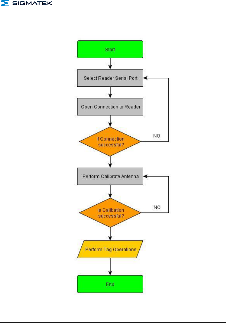
8 Communication Process Diagram
8.1 Connecting with the Reader
HF-RFID-READER
Page 52 PRELIMINARY
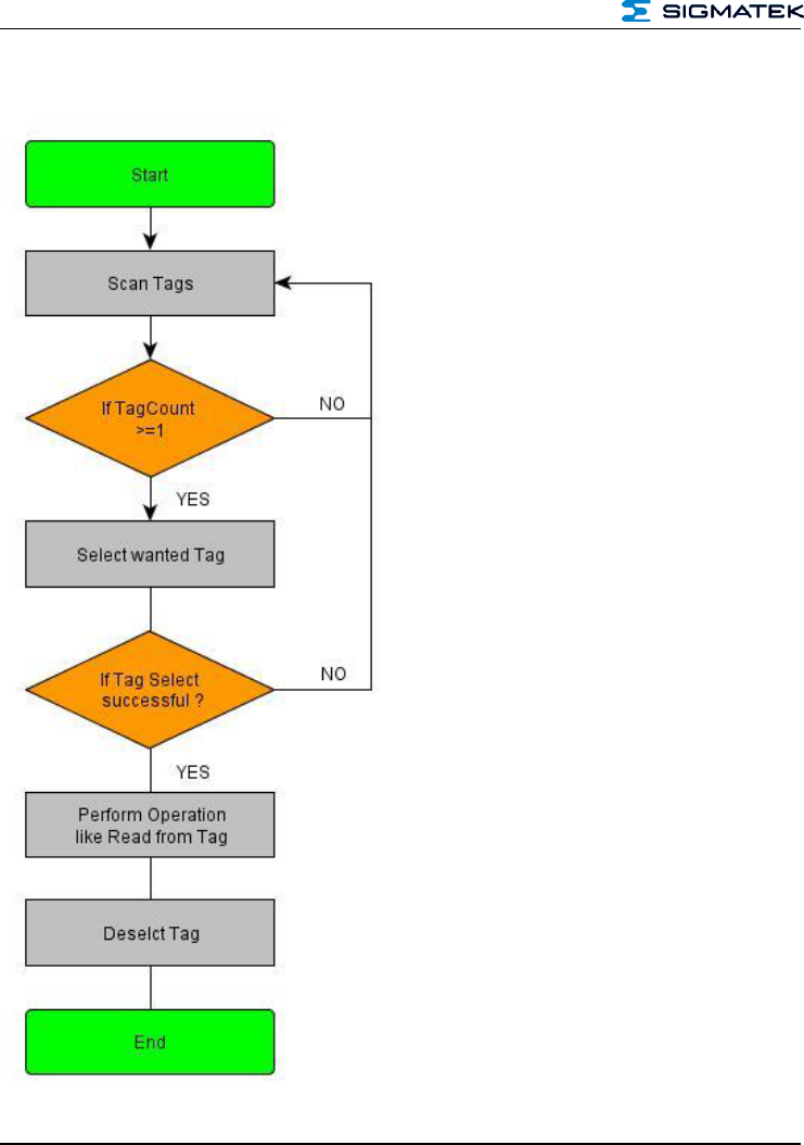
8.2 With Tag Communication

HF-RFID-READER
PRELIMINARY Page 53
9 Enumerators C
enum RFE_RET_VALUE
{
ERR_RET_SUCCESS = 0x00,
ERR_RET_PARAM,
ERR_RET_DATA_PUSH,
ERR_RET_CMD_INVALID,
ERR_RET_CRC,
ERR_RET_LENGTH,
ERR_RET_CMD_DATA,
ERR_RET_CALIBRATE_ANENA = 0x0F,
ERR_RET_TIMEOUT,
ERR_RET_FIFO,
ERR_RET_COLLISION,
ERR_RET_EXEC_CMD,
ERR_RET_CARD_NOT_SUPPORTED,
ERR_RET_AUTH,
};
enum ECMD
{
CMD_READER_NAME = 0x00,
CMD_PRODUCT_NAME,
CMD_SOFT_VERSION,
CMD_HARD_VERSION,
CMD_BOOT_VERSION,
CMD_CALIBRATE_ANTENNA,
CMD_SCAN_CARDS,
CMD_SELECT_CARD,
CMD_DESELECT_CARD,
CMD_READ_CARD,
CMD_WRITE_CARD,
CMD_OPTION_CARD,
CMD_GET_ATS,
CMD_SET_PPS,
CMD_EXEC_DESFIRE,
CMD_GPIO = 0x0F,
CMD_GET_FEATURE = 0x10,
CMD_SET_RSSI = 0x11,
};
enum ECMD
{
CMD_OPT_READ_AFI = 0x00,
CMD_OPT_WRITE_AFI,
CMD_OPT_LOCK_AFI,
CMD_OPT_READ_DSFID,
CMD_OPT_WRITE_DSFID,
CMD_OPT_LOCK_DSFID,
CMD_OPT_LOCK,
CMD_OPT_WRITE_KILL,
CMD_OPT_KILL,
CMD_OPT_LOCK_KILL,
CMD_OPT_SYS_INFO
};

HF-RFID-READER
Page 54 PRELIMINARY
enum CARD_TYPE
{ CARD_ISO14443A = 0x00,
CARD_ISO14443B,
CARD_ISO15693,
CARD_UNKNOWN = 0xFF,
};
enum CARD_SUBTYPE
{
MIFARE_ULTRALIGHT = 0x00,
MIFARE_MINI,
MIFARE_1K,
MIFARE_4K,
MIFARE_PLUS,
MIFARE_DES_FIRE,
MIFARE_ISO14443A_4,
ISO14443B_SRIX,
ISO14443B_SRIX176,
ISO15693_STANDARD,
CARD_SUBTYPE_UNKNOW = 0xFF,
};

HF-RFID-READER
PRELIMINARY Page 55
10 Declaration of Conformity
10.1 FCC Statement
This device complies with Part 15 of the FCC rules. Operation is subject to the following two conditions: (1) this device
may not cause harmful interference, and (2) this device must accept any interference received, including interference
that may cause undesired operation.
Section 15.21 Information to user
Changes or modifications not expressly approved by the party responsible for compliance could void the user's
authority to operate the equipment.
Section 15.105 (b)
Note: This equipment has been tested and found to comply with the Limits for a Class B digital device, pursuant to
part 15 of the FCC Rules. These limits are designed to provide reasonable protection against harmful interference in a
residential installation. This equipment generates, uses and can radiate radio frequency energy and, if not installed
and used in accordance with the instructions, may cause harmful interference to radio communications. However,
there is no guarantee that interference will not occur in a particular installation.
If this equipment does cause harmful interference to radio or television Reception, which can be determined by turn-
ing the equipment off and on, the user is encouraged to try to correct the interference by one or more of the following
measures:
Reorient or relocate the receiving antenna.
Increase the separation between the equipment and receiver.
Connect the equipment into an outlet on a circuit different from that to which the receiver is connected.
Consult the dealer or an experienced radio/TV technician for help.

HF-RFID-READER
Page 56 PRELIMINARY
Documentation Changes
Change date
Affected page(s)
Chapter
Note