Signal Communications SCNF-040113 TeleEye III+ Network Camera User Manual
Signal Communications Limited TeleEye III+ Network Camera
User Manual

NF Series
Network Camera
NF610
Installation Guide
Notice:
Signal Communications Limited reserves the right to make improvements to the
product described in this manual at any time and without notice.
This manual is copyrighted. All rights are reserved. This manual may not be copied,
reproduced or translated in whole or part without prior consent from Signal Communications
Limited.
Tele
Eye is a trademark of Signal Communications Limited and is registered in China, Hong Kong,
US and other countries.
All other trademarks are the property of their respective owners.
Copyright (c) 2003 Signal Communications Limited (A member of
Tele
Eye Group). All rights
reserved.
Version 1.1
Limits of Liability and Disclaimer of Warranty
Signal Communications Limited have taken care in preparation of this manual, but
makes no expressed or implied warranty of any kind and assume no responsibility for errors or
omissions. No liability is assumed for incidental or consequential damages in connection with or
arising out of the use of the information or accessories contained herein.
Features and specifications are subject to change without prior notice.

FCC Statement on Class B
WARNING
Changes or modifications to this unit not expressly approved by the party
responsible for compliance could void the user’s authority to operate the
equipment.
NOTE
This equipment has been tested and found to comply with the limits for a Class
B digital device, pursuant to Part 15 of the FCC Rules. These limits are designed
to provide reasonable protection against harmful interference in a residential
installation. This equipment generates, uses and can radiate radio frequency
energy and, if not installed and used in accordance with the instructions, may
cause harmful interference to radio communications.
However, there is no guarantee that interference will not occur in a particular
installation. If this equipment does cause harmful interference to radio or
television reception, which can be determined by turning the equipment off and
on, the user is encouraged to try to correct the interference by one or more of
the following measures:
Reorient or relocate the receiving antenna.
Increase the separation between the equipment and receiver.
Connect the equipment into an outlet on a circuit different from that to
which the receiver is connected.
Consult the dealer or an experienced radio/TV technician for help.
Shielded cables must be used with this unit to ensure compliance with the Class
B FCC limits.

Table of Contents
PREFACE
BEFORE YOU BEGIN 1
SECTION 1
INTRODUCTION 4
• Features 5
SECTION 2
INTERFACE DESCRIPTION
• Model: NF610 6
SECTION 3
FIRST TIME SET UP OF THE NETWORK CAMERA
• Network Camera Setup with IP Setup Utility 8
• Network Camera Setup with Crossover Ethernet Cable 10
• Network Camera Setup with Built-in Web-based Configuration 10
SECTION 4
SYSTEM CONFIGURATION AND INSTALLATION
• General System Configuration 12
• What you need
• General Configuration of Network Camera 14
A1. For Internal LAN Access 17
A2. For Broadband Internet Connection with Static IP 18
SECTION 5
NORMAL OPERATIONS OF THE NETWORK CAMERA
• Using Built-in Web Server 19

SECTION 6
GENERAL TERMS DISCUSSION
• Registration Checking 22
• Video Mode 22
• Built-in Web Server 22
• Site Monitoring Method 23
SECTION A
APPENDIX
• IP Address Setup for Window 98/ME 24
• IP Address Setup for Window NT/2000/XP 27
• Router Configuration 38
SECTION B
SPECIFICATIONS
• Model: NF610 29
Tele
Eye
III+
Network Camera Installation Guide Page 1
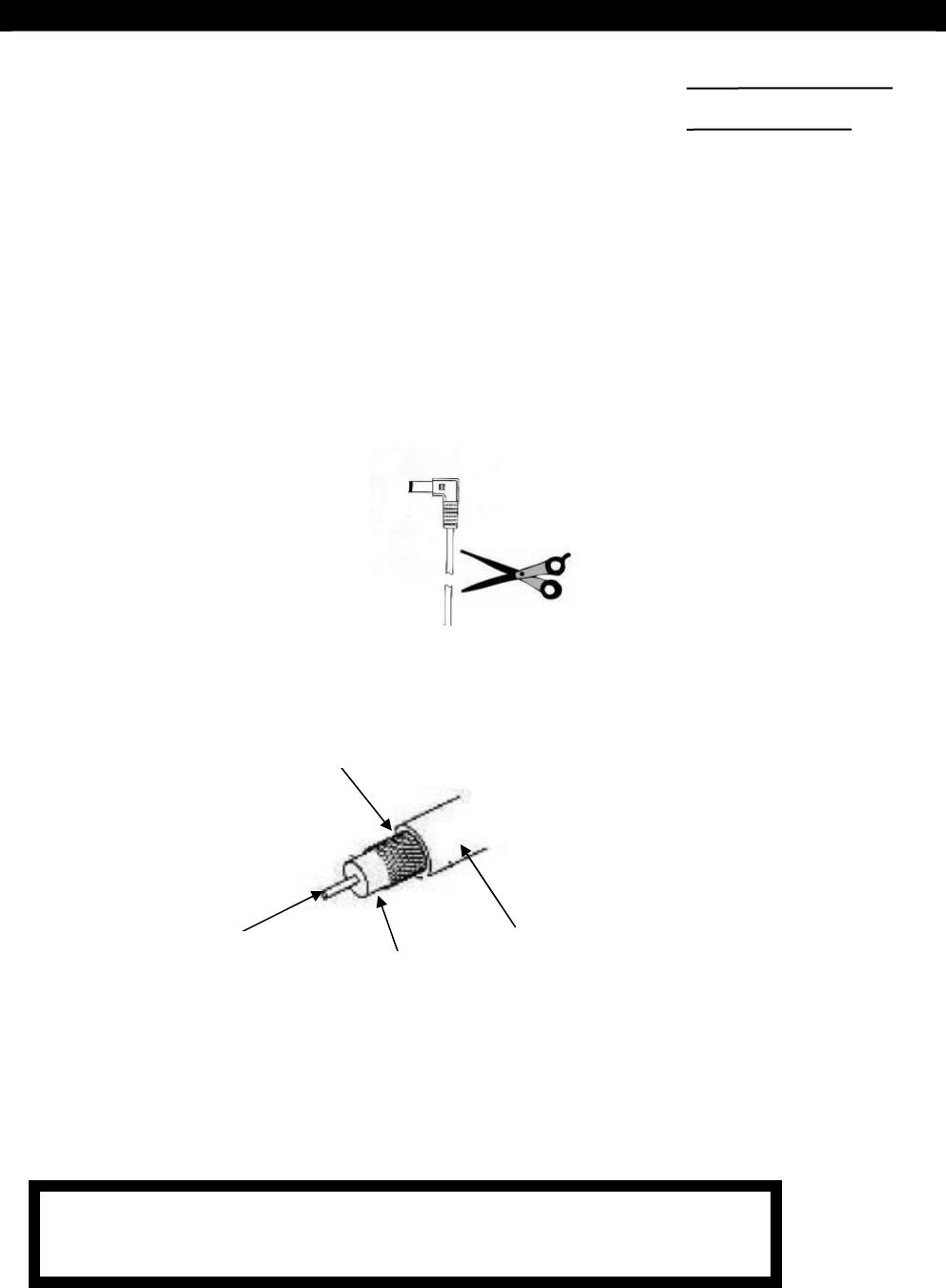
Before You Begin
BEFORE YOU BEGIN
Modification of the Power Adapter
The connector of the power adapter might require some modifications before connecting it
to the Network Camera.
1. Use a cutting tool to cut off the connector of the adapter
2. Strip the plastic covering off from the cable. You should see the cable is of the coaxial
type
3. After stripping off the plastic cover, you should see the braided GND wrapping
around the plastic shield. Unwrap the braided GND and twist it into a single
wire.
4. Strip off the plastic shield to reveal the 12V wire
5. Now, you should have a 12V wire and a separated GND wire.
PREFACE
Plastic Covering
Braided GND
Plastic
Shield
12V wire
CAUTIONS: NEVER SHORT THE 12V AND GND WIRES. With
the power on, damages may be incurred to the adapter.
Tele
Eye
III+
Network Camera Installation Guide Page 2
Before You Begin
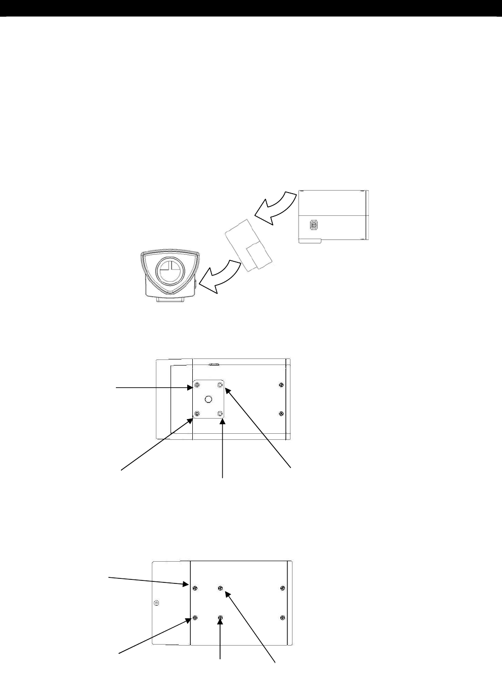
Repositioning of the Mounting Plate
At the bottom of the Network Camera is a mounting plate. The mounting plate can also be
removed and re-attached to the top of the Network Camera. The following is the procedure
for repositioning the mounting plate from the bottom to the top of the Network Camera.
IMPORTANT: TO PREVENT DISMANTLING OF THE NETWORK CAMERA, DO
NOT SIMPLY REMOVE ALL THE SCREWS FROM THE MOUNTING PLATE.
Please follow the procedures below.
1. Remove all the screws (1 – 4) from the bottom of the Network Camera.
2. Take off the plate.
3. Remove the 7
th
, and the 8
th
screws at the top of the Network
5
6
7 8
Bottom View
Top View
1
2
3
4
Wrong!!!

Tele
Eye
III+
Network Camera Installation Guide Page 3
Before You Begin
4. Re-secure the screws just removed to position 1 and 2 at the bottom of the Network
Camera. This is to prevent the dismantling of the camera.
5. Remove the screws in position 5 and 6.
6. Re-attach the screws just removed to position 3 and 4 at the bottom of the Network
Camera
7. Position and align the mounting plate to the screw holes at the top of the camera
8.
Put on the rest of the screws to fasten the plate to the camera.

Tele
Eye
III+
Network Camera Installation Guide Page 4
Introduction
1
INTRODUCTION
The
Tele
Eye
III+
Network Camera NF 610 is a brand new member of the
Tele
Eye
III+
Network CCTV family. It combined the power of high performance imaging technology
and swift video transmission into a single module.
With the built-in web server, remote video surveillance can readily be conducted with
standard web browsers over the Internet or LAN. The availability of simple connections
with the Internet or LAN makes the construction of scalable network surveillance easy.
Further enhanced with the proprietary sureLINK technology, low cost dynamic IP
broadband Internet connection is also supported.
The Network Camera also comes with Intelligent Event Handling. With the embedded event
handling mechanism, the Network Camera is prepared to accept the challenges of real-life
situation such as alarm trigger or system failure. Actions will be taken automatically by the
camera to counter each different scenario.
With its many powerful features, remote video monitoring has never been made easier than
before. Simply connect to the Network Camera anytime, anywhere, and be ready to view
some high quality live streaming video, at your convenience.
SECTION

Tele
Eye
III+
Network Camera Installation Guide Page 5
Introduction
Features
• 1/3” colour CCD
• Illumination 1 Lux
• Back light compensation
• Flexible connections – Internet, LAN, ADSL and cable modem
• Real time video transmission up to 30 fps over LAN for NTSC; up to 25 fps over
LAN for PAL
• Resolution up to 640x480 pixels
• Support static and dynamic IP
• Built-in web server
• Event-driven recording
• Composite video output
• Web video development tool
• Mobile video on pocket PC
• Event management
• Pre- & post-alarm recording
• Multiple users video access
• Single- & multi-site monitoring
• Internet clock synchronization
Tele
Eye
III+
Network Camera Installation Guide Page 6
Interface Description
2
INTERFACE
DESCRIPTION
Model: NF610
The rear panel of the
Tele
Eye
III+
Network Camera NF610 is shown below:
Functional Description of NF610
Collision & Link LED Status
- COL LED: when on, indicates that collision is occurring on the network
- LINK LED: when on, indicates that
Tele
Eye
III+
Network Camera is connecting to the
network and ready to function
Ethernet Socket (10/100 Base-T)
- This socket is used for connecting
Tele
Eye
III+
Network Camera to the corporate
computer network (e.g. LAN)
ALARM & SWITCH Port
- This port is used for connecting the alarm sensor input
- It can also be remotely controlled by the Reception Software
SECTION
Tele
Eye
III+
Network Camera Installation Guide Page 7
Interface Description
PIN Signal
P1 PIN for alarm device (NC / NO)
P2 Common GROUND
P3 Dry Contact
P2 P1P3P4
P4 Dry Contact
Power LED
- PWR LED: when on, indicates that the Network Camera has been power up successfully
VIDEO OUT Connector
- Standard BNC connector for color video
- A composite video signal should be supplied from this connector
Power Terminal
- A power terminal for the connection to the power supply (12V D.C.)

Tele
Eye
III+
Network Camera Installation Guide Page 8
First Time Setup of Network Camera
3
FIRST TIME SETUP OF THE
NETWORK CAMERA
Before installing the Network Camera, its IP address must be set so that an Ethernet
connection can be established to the Network Camera from a computer. In order to do this,
either the IP address of the Network Camera or the IP address of the PC should be modified.
This is very important since the Network Camera has default IP address, 192.168.0.2, which
might not be suitable for your existing network.
You can use either IP Setup Utility or Crossover Ethernet Cable for configuration of
Network Camera.
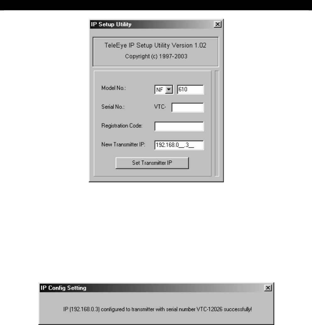
Network Camera Setup with IP Setup Utility
IP Setup Utility is a simple, user-friendly software to set a new IP address to a Network
Camera. To assign a new, valid IP address to the Network Camera, follow the steps
described below.
Step 1: Connect the Network Camera to your network by connecting a straight Ethernet cable from
the Network Camera Ethernet Port to a hub/switch. Alternatively, use a crossover Ethernet
cable to direct connect a computer with the Network Camera alone. Actually, there are
different approaches in installing the Network Camera to different types of network. For details
on installing Network Camera, please refer to Section 4 System Configuration and Installation.
IMPORTANT: IP Setup Utility can only be used to configure the Network Camera IP address within
the first 20 MINUTES immediately after the Network Camera is power up. After the first 20 minutes
expired, IP Setup Utility cannot configure the Network Camera IP at all. After this time frame has
been expired, you must turn off the Network Camera by disconnecting the power source from the
Network Camera, then power up the Network Camera again to regain the 20 minutes time window.
Step 2: Power on the Network Camera. The green power indicator light should be on. The LINK
indicator light should also be on. If not, check the power and the network connection between
the Network Camera and the hubs/switches/computer.
Step 3: Run IP Setup Utility from your computer.
SECTION
Tele
Eye
III+
Network Camera Installation Guide Page 9
First Time Setup of Network Camera
Step 4: Select “NF” and enter Model No. (e.g. NF-610).
Step 5: Enter the Network Camera Serial Number and Registration Code to the fields provided.
Step 6: Insert a new, valid IP address of your desire to the provided field (e.g. 192.168.0.3).
Step 7: Click on Set Transmitter IP button to set the Network Camera to the new IP address.
Step 8: The program should now searching through the network to verify that the IP address you
requested is not already in use. The indicator bar on the right side shows the progress of the
current operation. If the setup is successful, the following window message should appear.
The Network Camera should have a valid IP address by now. You can continue to setup
Network Camera using built-in web-based configuration.
Tele
Eye
III+
Network Camera Installation Guide Page 10
First Time Setup of Network Camera
Network Camera Setup with Crossover Ethernet Cable
Your computer is required to change the IP address (e.g. 192.168.0.3). Please refer to
Section A Appendix for a detailed descriptions for IP configuration on different operating
systems.
If your computer has changed the IP address, you can connect Network Camera by plugging
Crossover Ethernet Cable from your computer to Ethernet port of Network Camera. You
can continue to setup Network Camera using built-in web-based configuration.
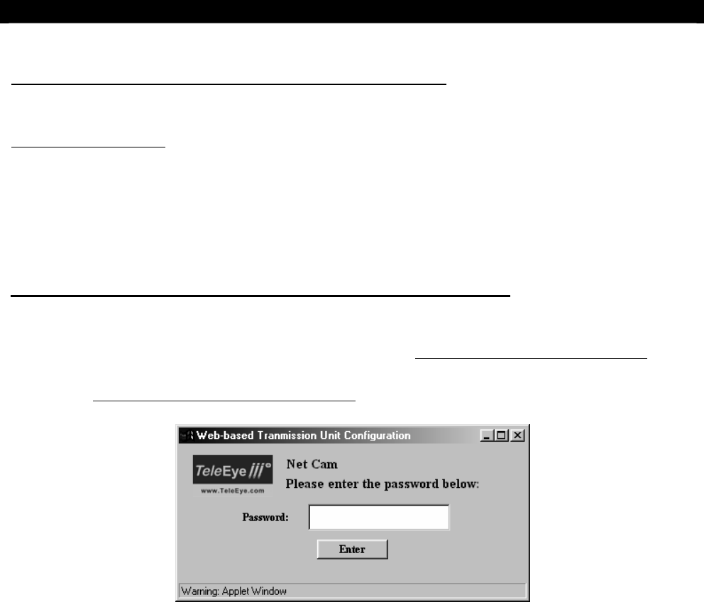
Network Camera Setup with Built-in Web-based Configuration
After you have assigned an IP address to your Network Camera, you can access Network
Camera configuration page in your web browser (e.g.
http://192.168.0.3:1024/setup.htm
). You
might need to enable Java in your web browser or to download the latest version of the Java
VM (go to
http://java.sun.com/getjava/index.html
).
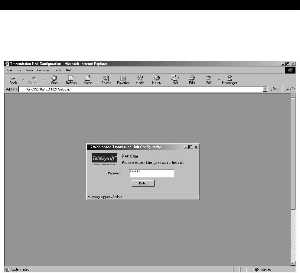
To enter Network Camera configuration, follow the steps below:
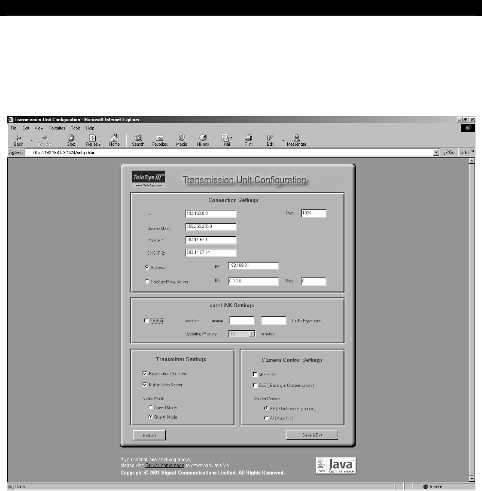
Step 1: Enter default administrator password “000000” and click on Enter button. The following
page will be displayed and loaded with current Network Camera Settings.
Tele
Eye
III+
Network Camera Installation Guide Page 11
First Time Setup of Network Camera
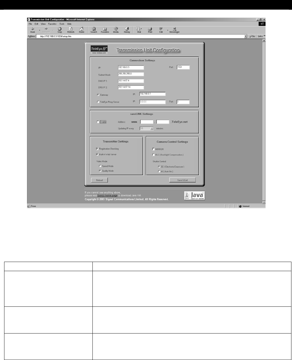
Step 2: You can change the connection, sureLINK, transmitter properties and camera control
settings. You can reload the configuration by clicking Reload button. Click on Save & Exit
button to save the changes.
The description of each setting type is listed below:
Setting Type Description
Connection Settings You can set IP address, port, subnet mask, gateway and DNS
as well as
Tele
Eye Proxy Server settings. For a detailed
description, please refer to section “System Configuration and
Installation”.
sureLINK Settings You can enable sureLINK support in Network Camera. For a
detailed description, please refer to section “sureLINK
Technology”.
Transmitter Settings You can setup Network Camera for the other functions. For a
detailed description, please refer to section “General Terms
Discussion”.

Tele
Eye
III+
Network Camera Installation Guide Page 12
System Configuration and Installation
4
SYSTEM CONFIGURATION
AND INSTALLATION
This section will discuss how to setup the Network Camera and modify its settings in details.
Installations of the Network Camera with different types of network will also be discussed.
Specifically, installations with the following types of network will be discussed.
Network Types:
A1. For Internal LAN Access
A2. For Broadband Internet Connection with Static IP
B1. For Broadband Internet Connection with Dynamic IP using Router
B2. For Broadband Internet Connection with Dynamic IP using Broadband Dialer
Procedures that are common to all configurations and installations approaches will be
discussed first followed by the steps that are specific to each particular network setup. The
configuration utility is web-based. Furthermore, it is assumed that a valid IP address has
been assigned to the Network Camera and a connection can be established to the Network
Camera.
What You Need
To configure and set up the Network Camera, the following basic items are required:
Hardware:
Tele
Eye
III+
Network Camera
This is what you have purchased.
PC - Minimum Requirement:
Pentium II 350 MHz or above
Windows 98/ME/NT/2000/XP Operating System
64MB RAM for Windows 98/ME, 128MB RAM for Windows
NT/2000/XP
Power Adaptor
A 12 VDC power adaptor.
SECTION

Tele
Eye
III+
Network Camera Installation Guide Page 13
System Configuration and Installation
RJ-45 Network Cable
It is a shielded, straight-through RJ-45 network cable. The cable will connect
the
Tele
Eye
III+
Network Camera to the hub of the LAN for typical
application.
Crossover Network Cable
Used to connect between a router and PC or the Network Camera
Software
Web-browser
A standard web-browser such as IE, and Netscape…etc.
Information
Valid IP address for the Network Camera.
Administrator Password for the Network Camera (The default
administrator password is “000000”. You can change it in the
Reception Software)
Port number for the Network Camera (default value is 1024)
Your network subnet mask
Your network gateway address (required by Network Types B1 & B2)
2 DNS addresses ( Please ask your ISP for this information; required by
Network Types B1 & B2)

Tele
Eye
III+
Network Camera Installation Guide Page 14
System Configuration and Installation
General Configuration of Network Camera
After you prepared all the things discussed in previous section, you should be ready to
configure the Network Camera.
Note: Make sure the computer in use is capable of connecting to the Internet or the Local Area
Network (LAN). Also make sure your browser supports Java.
Step 1: Plug the RJ-45 network cable into the socket on the hub's/switch’s rear panel. Afterwards,
plug the other end of the network cable into the socket on the
Tele
Eye III+ Network
Camera's Ethernet Port.
Step 2: Power on the hub/switch
Step 3: Another way to connect to the Network Camera is to attach a crossover Ethernet cable from
a computer to the Network Camera directly.
Step 4: Turn on the
Tele
Eye III+ Network Camera.
The green POWER light should be activated if
the Network Camera is successfully turned on. The LINK indicator light should also be on if
it is connected to the network. If the POWER light remains off, check the power supply and
connection. If the LINK light remains off, check the network connection.
Step 5: If a valid IP address has not been assigned to the Network Camera, run IP Setup Utility
from your computer.
Step 6: Enter the Network Camera Serial Number and Registration Number to the fields provided.
Step 7: Insert a valid, new IP address of your desire to the provided field.
Step 8: Press on the Set Network Camera IP button to set the Network Camera to the new IP
address.
Step 9: Run your favourite web-browser
Step 10: You are now ready to configure the Network Camera. Enter the Network Camera’s IP
address and port number to the address field of your web-browser. The format should
conform with:
http://xxx.xxx.xxx.xxx:yyyy/setup.htm
where xxx.xxx.xxx.xxx is IP
address and yyyy is port number.
Tele
Eye
III+
Network Camera Installation Guide Page 15
System Configuration and Installation
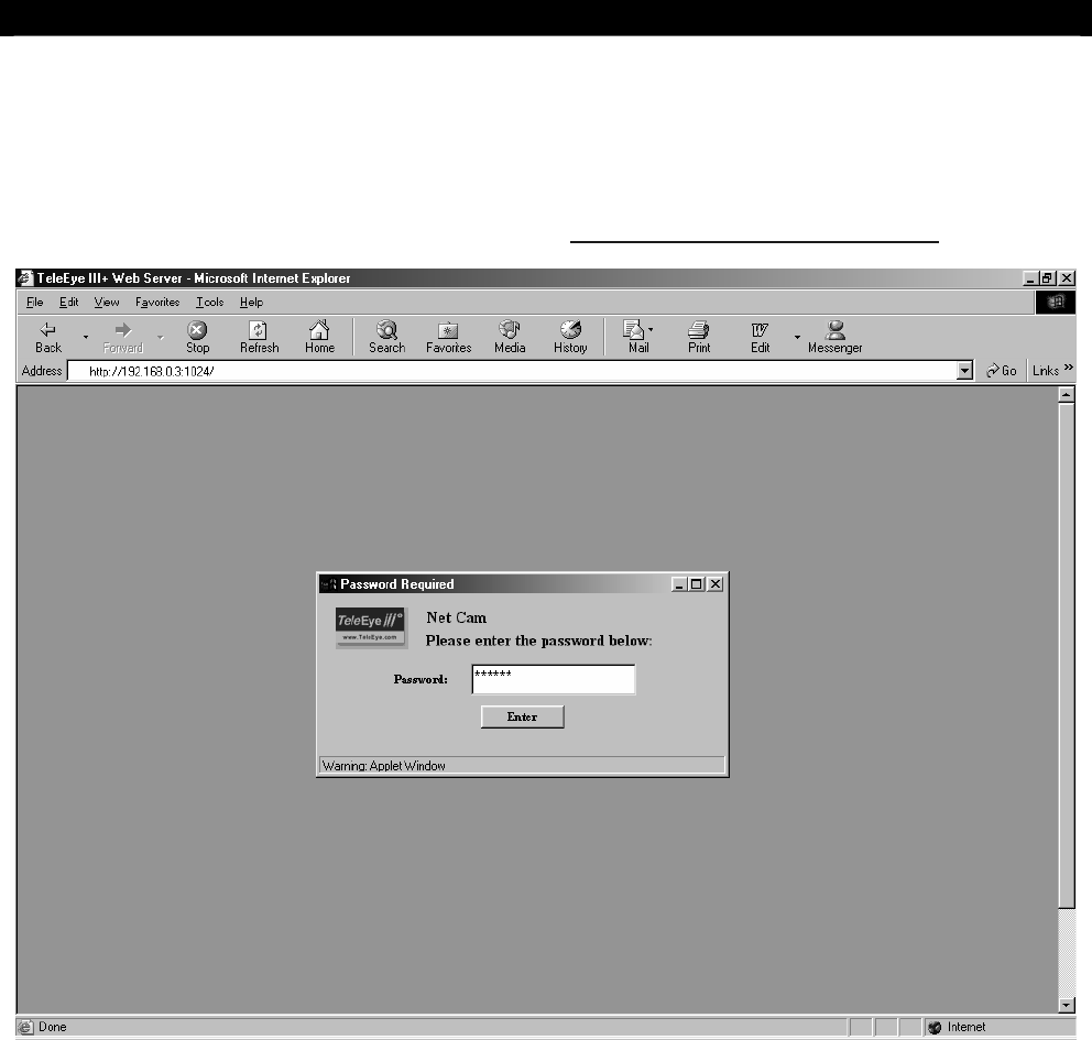
The Network Camera’s web-based configuration should already be displayed in your web-
browser. It should be similar to the captured screen shown below. Please enter the default
administrator password “000000” to login.
Tele
Eye
III+
Network Camera Installation Guide Page 16
System Configuration and Installation
There are many settings to be configured, such as Video Mode, Gateway, DNS…etc. The
camera features can also be configured now. For users who have little knowledge in camera
settings, it is advised that users read the section in camera features before making any
changes.
Tele
Eye
III+
Network Camera Installation Guide Page 17
System Configuration and Installation
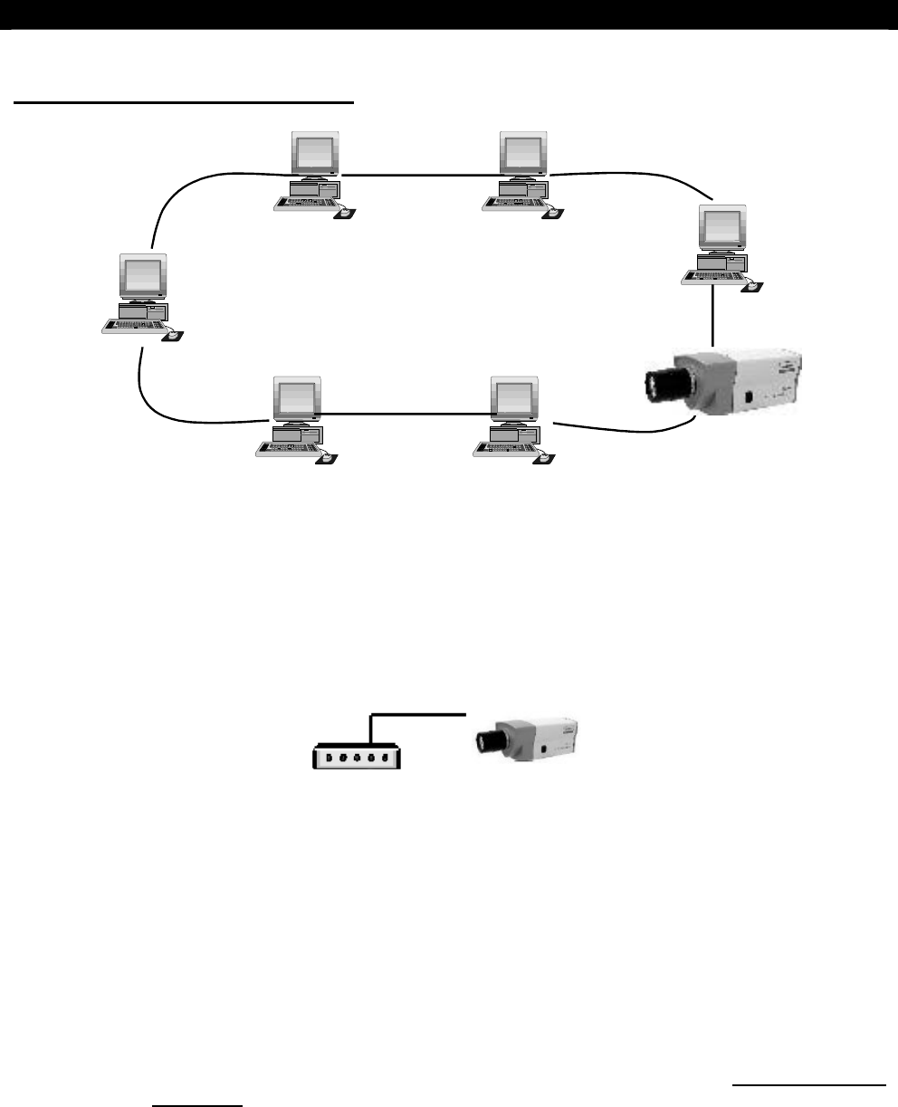
A1. For Internal LAN Access
Step 1: To continue, configure the Registration Checking and Video Mode settings.
Step 2: You can Enable the Built-in Web Server so that you can see video through web browser
Step 3: Ensure all settings are correct, then press the Save and Exit button
Network Camera Installation
RJ-45 Network
Cable
Hub
Step 1: Plug the RJ-45 network cable into the socket on the hub's rear panel. Afterwards, plug the
other end of the network cable into the socket on the
Tele
Eye III+ Network Camera 's rear
panel.
Step 2: Plug the hub power cable into the hub power connector. At the same time, plug the hub
power supply into a wall let and power on the hub.
Step 3: Plug one end of the BNC cable a TV monitor, then plug the other end to the
Tele
Eye III+
Network Camera 's VIDEO OUTPUT connector, if local monitoring is required.
Step 4: Connect alarm sensor to the corresponding pins of the ALARM & SWITCH port, if
necessary (For the pin assignment of the ALARM port, please refer to Section 2 Interface
Description).
Step 5: Power up the Network Camera with the adaptor provided. The power LED and the LINK
LED on the rear panel should light up.
Tele
Eye
III+
Network Camera Installation Guide Page 18
System Configuration and Installation
Step 6: You may now use the web-based graphical user interface or the
Tele
Eye III+ Reception
Software to connect to the Network Camera. For the instructions of using the software,
please refer to the
Tele
Eye III+ Reception Software User Guide.
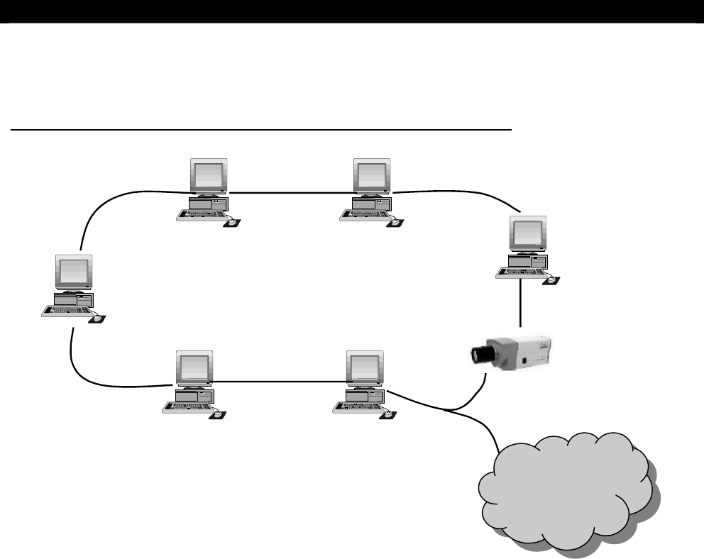
A2. For Broadband Internet Connection with Static IP
Internet
Please follow the configuration and installation steps of A1. Internal LAN Access. You
have to set the Gateway IP of the Network Camera.

Tele
Eye
III+
Network Camera Installation Guide Page 19
Normal Operations of the Network Camera
5
NORMAL OPERATIONS OF THE
NETWORK CAMERA
Having completed the IP setup of the Network Camera, you are now ready to see live
streaming video from the Network Camera. To start viewing video, all that is required is a
computer with network capability and a Java supporting, standard web browser. To view
video from the Network Camera is very similar to how you browse the Internet.
Using Built-in Web Server
Before using the web service, you have to make sure that you have ENABLED the Built-in
Web Server feature when configuring the Network Camera. For details please read
Network Camera Configuration. In web browser, you can enter your registered
sureLINK address (e.g. http://www.network.camera.teleeye.net/) or IP address with port
number (e.g. http://192.168.0.3:1024/) to connect your Network Camera.
Step 1: Make sure the computer in use is capable of connecting to the Internet or the Local Area
Network (LAN). Also make sure your browser supports Java.
Step 2: Connect the Network Camera to your network by connecting a straight Ethernet cable from
the Network Camera Ethernet Port to a hub/switch. Alternatively, use a crossover Ethernet cable to
direct connect a computer with the Network Camera alone. Actually, there are different approaches in
installing the Network Camera to different types of network. For details on installing Network Camera,
please refer to Section 4 System Configuration and Installation.
Step 3: Run your favourite web browser. At the address field at the top, enter the IP address of the
Network Camera in this format:
http://IP_address:port_number.
For example,
http://192.168.0.3:1024
. The IP is 192.168.0.3. The port number is 1024 which is the default port
number of the Network Camera.
SECTION
Tele
Eye
III+
Network Camera Installation Guide Page 20
Normal Operations of the Network Camera
Step 4: A window should appear. Please enter the password. The default password is 000000. The
location name and the password can both be changed with the
Tele
Eye III+ Reception Software,
WRS3-AD.
If problems arise, please check that your browser supports Java. You might need to enable Java or to
download the latest version of the Java VM (go to http://java.sun.com/getjava/index.html).
Step 5: After a correct password has been entered, the main screen should appear.
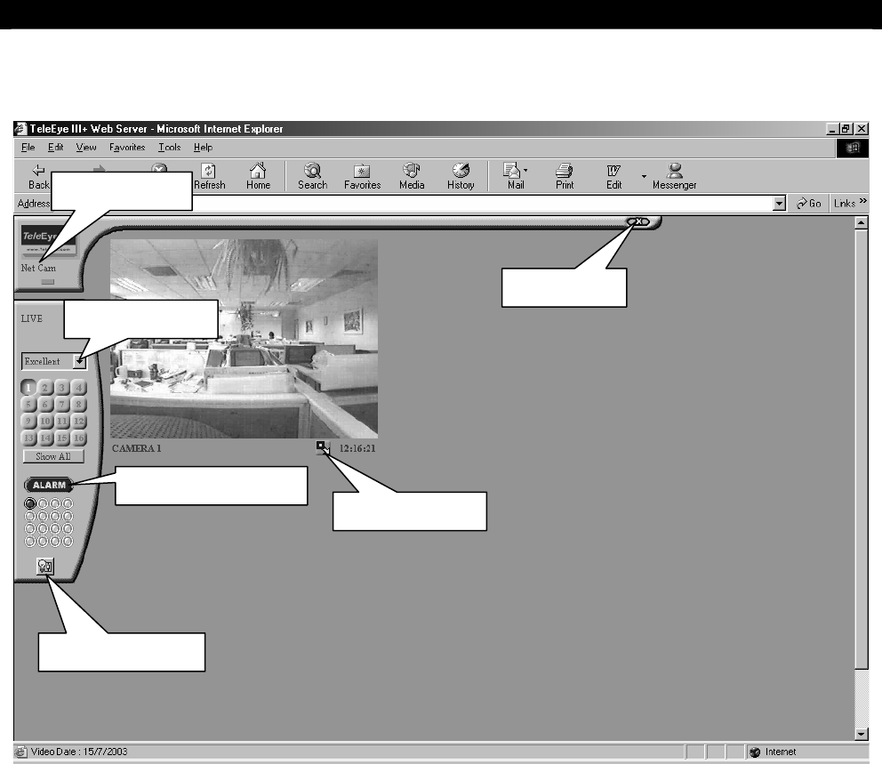
On the left of the screen, starting from the top,
I. Location Name: Indicates which Network Camera that currently connected to
II. Green Light: Indicates that live video is in transmission if flashing
III. Image Quality Menu: Selects the quality of the Video
IV. Keypad: Only one camera available for Network Camera.
V. Show All Button: If selected, video will display in the top left corner of the Video Screen.
VI. Clear Alarm Button and Alarm Indicator Light: Alarm indicator light in dark green color
means no alarm is triggered; red color means alarm is triggered; light green color means
alarm has been triggered before. Press once on the Alarm button to clear alarm
VII. Switch Control Button: ON/OFF control of the Relay switch
VIII. Video Screen: Displays live streaming video
IX. Maximize Button: Switches the video display to full screen mode
X. Clock: Shows the current time of Network Camera
Tele
Eye
III+
Network Camera Installation Guide Page 21
Normal Operations of the Network Camera
The main screen is where most actions take place.
This web-based approach is the simplest way to connect with Network Camera. No other
special software is required; it is just as easy as ordinary web browsing. On the other hand,
the
Tele
Eye III+ Reception Software WRS3-AD can also be employed to connect and to
view live video from the Network Camera.
Maximize Button
Location Name
Image Quality
Switch Control
Clear Alarm Button
Exit Button

Tele
Eye
III+
Network Camera Installation Guide Page 22
General Terms Discussion
6
GENERAL TERMS DISCUSSION
To familiarize you with the Network Camera, you may need to know some of the terms and
information below.
Registration Checking
Users need to do the registration in the Reception Software (e.g. WRS3-AD) for
authorization before the Network Camera can be used when such feature is enabled in
the
Tele
Eye
III+
Network Camera. This option can be applied to improve the security
protection for the organization when higher security level is required. If the Network
Camera is decided to open for public use, you can disable this feature so that public
users do not need to register for viewing live video from the Reception Software.
Video Mode
There are two sets of video resolution settings available in the Network Camera. The
Speed set offers 128x96, 256x192 and 512x384 pixels while the Quality set offers
160x120, 320x240 and 640x480 pixels. As the name indicated, the Speed set will
increase the Network Camera’s video performance in speed while the Quality set in
quality. You can only have one set being active during the Network Camera’s day-to-
day operation. This setting should be configured during the installation of the Network
Camera. For ideal performance in speed, please choose the Speed option.
Note that you cannot set the video performance at the client side software (i.e. WRS3-
AD) which is used to monitor the site through the Network Camera. Instead, you can
only do so while configuring the Network Camera.
Built-in Web Server
In order to let you view live video anywhere, at anytime, in the most convenient way,
you can enable the Built-in Web Server so that any PCs connecting to the Internet can
view your remote site without installing or configuring any software. In this case, when
you go traveling or on trips, you can also view the site by just using web browser! No
additional procedures or settings are needed and you can just enter your site address (e.g.
http://www.hkoffice.teleeye.teleeye.net) at the web browser and view the site
immediately. To see how to use this, please read section 5.
The above items are recommended to be configured before the first time you use the
Network Camera no matter which connection method you use. The steps to set the above
items will be discussed in Network Camera Configuration of different configuration
under System Configuration and Installation section.
SECTION

Tele
Eye
III+
Network Camera Installation Guide Page 23
General Terms Discussion
Site Monitoring Method
There are mainly three methods to link up with the Network Camera to see videos:
TCP/IP in LAN
TCP/IP on the Internet using Broadband and Internet Router
TCP/IP on the Internet using Broadband with Dial-up Software
You have to choose one of the System Configuration Methods in earlier section to
configure
Tele
Eye
III+
’s Network Camera before use so as to make it function
properly.
The Network Camera configuration program contains all the settings for different
remote video monitoring method. Different connection methods may have different
settings, and some of the setting configured in one connection method is not
applicable to other method. In this case, you can refer to one of the configuration
procedures from the preceding section for the connection method you use.
Tele
Eye
III+
Network Camera Installation Guide Page 24
Appendix
A
APPENDIX
IP Address Setup for Windows 98/ME
The follow procedures will set your Ethernet Card IP address manually for your local
LAN purpose. Note that these procedures will NOT affect your PC to get on the Internet.
If you discover that you cannot be able to access on the Internet after applying the
settings, you have to undo the settings or re-install the software provided by your ISP and
retry the steps again.
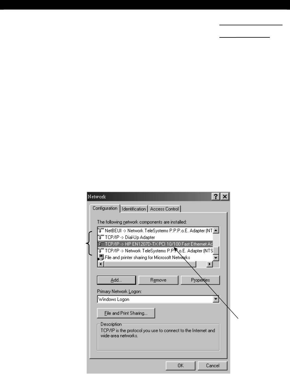
Step 1: In Windows 98/ME desktop, select Start > Settings > Control Panel
Step 2: Double click Network > Configuration, you will find that there are at least 2 fields (usually 3
fields) started with “TCP/IP ->”.
3. TCP/IP
Your Ethernet
card name
SECTION
Tele
Eye
III+
Network Camera Installation Guide Page 25
Appendix
Two of them are very important for setup. One of them is used for your local intranet (the field
may contain the name of your Ethernet card), the other one is used for your broadband Internet
connection. An example is shown in the following figure.
TCP/IP-> HP EN1207D-TX PCI 10/100 Fast
Ethernet Adaptor Used for Intranet (local network)
TCP/IP-> Network TeleSystems P.P.P.o.E
Adaptor Broadband Internet Access (Point-to-Point
Protocol over Ethernet)
Note that the name of these two TCP/IP adaptors may be different on your computer. You have to
identify the purpose of each corresponding adaptor.
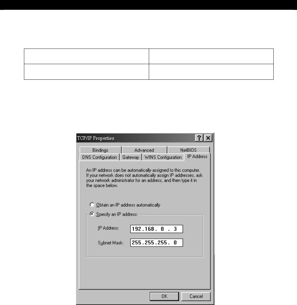
Step 3: Choose TCP/IP->[Your Ethernet card name] > Click Properties > IP address, enter an IP
address “192.168.0.3” and subnet mask “255.255.255.0”
Step 4: Click OK and OK and reboot the computer.
Step 5: After booting, ensure that the computer can still be connected to the Internet.
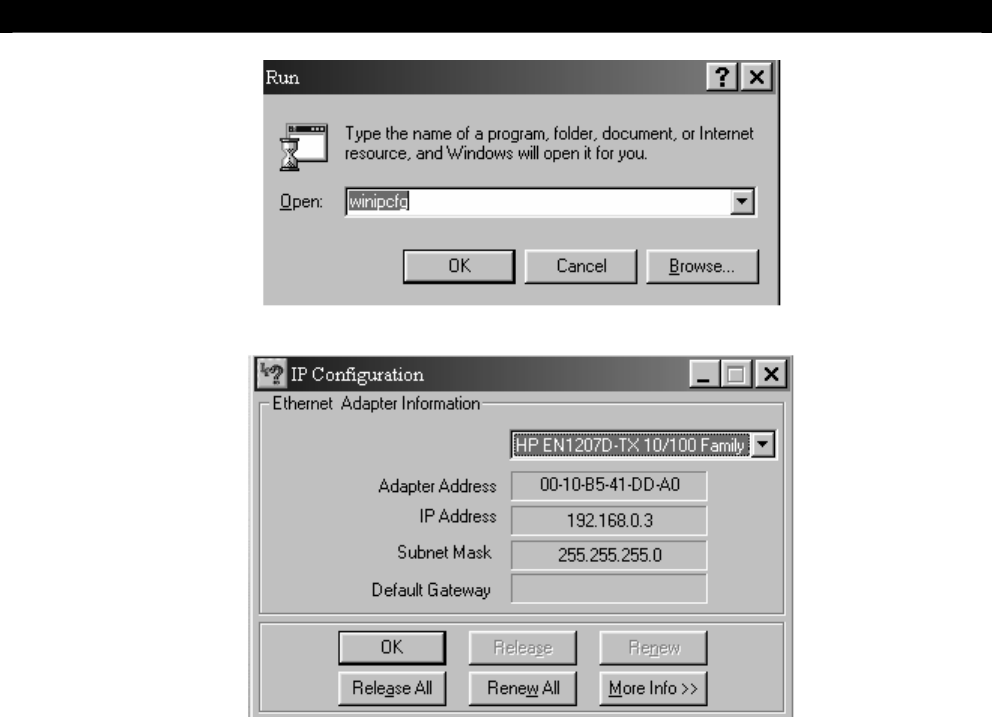
Step 6: You have to confirm the IP address has been correctly set on your computer. On your windows,
click start > run, type “winipcfg” at Open field and pressed OK button, then you will see a IP
Configuration program shown as figure.
Tele
Eye
III+
Network Camera Installation Guide Page 26
Appendix
Step 7: Select your Ethernet card name on the field, you will see a IP address on the field. Ensure that
that is the same as you have set before (i.e. 192.168.0.3). If it is not so, please repeat step 12.
Click OK to close the program.
Tele
Eye
III+
Network Camera Installation Guide Page 27
Appendix
IP Address Setup for Windows NT/2000/XP
The follow procedures will set your Ethernet Card IP address manually for your local
LAN purpose. Note that these procedures will NOT affect your PC to get on the Internet.
If you discover that you cannot be able to access to the Internet after applying the settings,
you have to undo the settings or re-install the software provided by your ISP and retry the
steps again.
Step 1: In Windows NT/2000/XP desktop, select Start > Settings > Control Panel
Step 2: Double click Network and Dial-up Connections > right click Local Area Connections and
choose Properties.
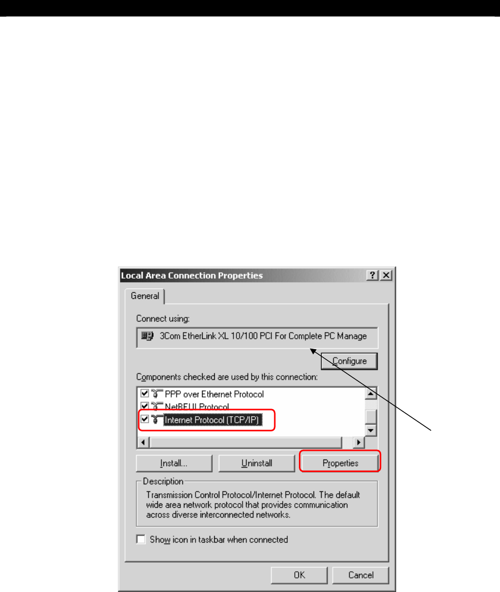
Step 3: Choose Internet Protocol (TCP/IP) and click Properties
Your Ethernet
card name
Tele
Eye
III+
Network Camera Installation Guide Page 28
Appendix
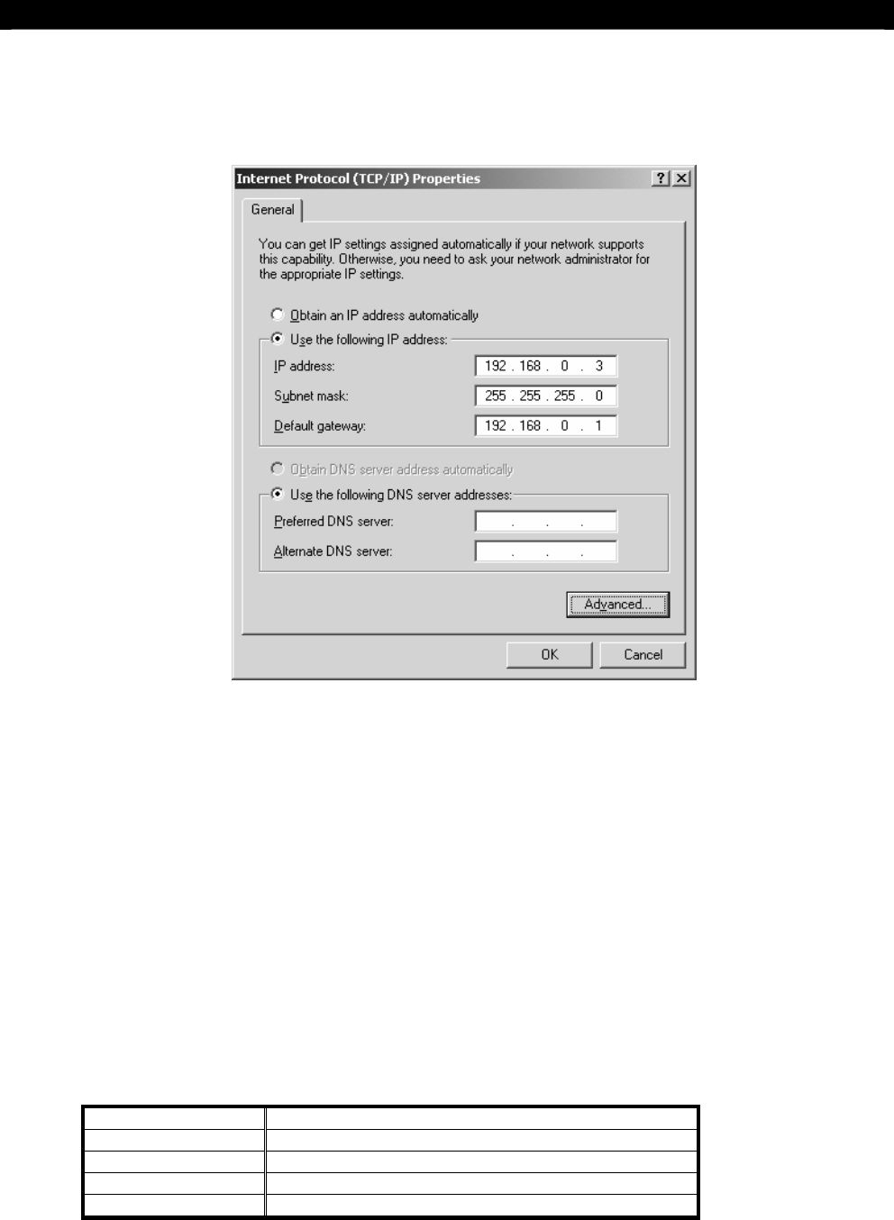
Step 4: Enter an IP address, subnet mask and Default gateway.
Step 5: Enter the Preferred and Alternate DNS server, if necessary.
Step 6: Click OK to activate the new IP.
Step 7: You have to confirm the IP address has been correctly set on your computer. On your windows,
click start > run, type “cmd” at Open field and pressed OK button, then type “ipconfig” on
the DOS prompt, you will see a IP set on your computer.
Router Configuration
Port Mapping in your Router
For PLANET Internet SOHO Router XRT-101 / XRT-711, please refer to its menu
6.1 Advanced Internet Features →
Virtual Servers (Define servers on your LAN, so Internet users can access them)→
E.3 User-defined Virtual Servers
Suggested Data for router:
Name TeleEye
IP Address 192.168.0.2 (Your Network Camera IP address)
Protocol TCP
Internal Port No. 1024
External Port No. 1024

Tele
Eye
III+
Network Camera Installation Guide Page 29
Specifications
B
SPECIFICATIONS
MODEL NF610
IMAGE SENSOR
Type 1/3" CCD, 16M colour, interlace
Minimum Illumination 1.0 Lux at F/1.2
Electronic shutter (P): 1/50-1/100,000 second
(N): 1/60-1/100,000 second
on/off switchable
Back Light Compensation on/off switchable
White Balance automatic
Resolution Quality Mode: 640x480, 320x240, 160x120
Speed Mode: 512x384, 256x192, 128x96
Video Output (P): PAL/CCIR, 625 lines, 50 fields per second
(N): NTSC/EIA, 525 lines, 60 fields per second
composite video, 1Vp-p, BNC
LENS
Mounting CS mount (C mount adaptor option)
CONNECTION
Network RJ-45, 10/100 Base-T Ethernet
No. of Concurrent Users 4
Web Server built-in web server
sureLINK supports Internet connection assigned with dynamic IP address
RS - 485 N/A
PCMCIA N/A
EVENT HANDLING
Event external alarm, system failure
Action dial back, relay control, email notification
External Input 1, NC/NO
RELAY SWITCH
Channel 1 channel, latched/momentary
Max. Rating 24V AC 1000 mA
POWER
Voltage 12V DC
Max. Rating 800 mA
OPERATING ENVIRONMENT
Ambient Temperature 0
o
C - 50
o
C
Relative Humidity < 90% (no condensation)
MECHANICAL DESIGN
W x D x H 85 x 153 x 775 (mm x mm x mm)
Net Weight 0.9 kg
SECTION