Signal Technology MO-1045 MicroObserver Sensor Node User Manual
Signal Technology Corporation MicroObserver Sensor Node
User Manual

MicroObserver
Unattended Ground Sensor System
PRELIMINARY
Users Manual
Models M-100 & MO-1045
ITAR NOTICE
This product and/or its technical data are export controlled by the U.S. State Department and covered by the
International Traffic in Arms Regulations (ITAR). It may not be exported or transferred to any foreign person
in the United States or abroad, except as authorized by the U.S. Department of State or the ITAR. Violators of
these export laws are subject to severe civil and criminal penalties.
2
FCC Information
Note: This equipment has been tested and found to comply with the limits for a Class A
digital device, pursuant to Part 15 of the FCC. rules. These limits are designed to provide
reasonable protection against harmful interference when the equipment is operated in a
commercial environment. This equipment generates, uses, and can radiate radio frequency
energy and, if not installed and used in accordance with the instruction manual, may cause
harmful interference to radio communications. Operation of this equipment in a residential
area is likely to cause harmful interference, in which case, the user will be required to correct
the interference at his own expense.
Caution: FCC approved RF operation of this equipment is permitted only with the approved
antennas, cable and connectors provided with this product.
FCC Notice: Changes or modifications to this device not expressly approved by the
manufacturer could void the user’s authority to operate the equipment.
FCC Radiation Exposure Statement
This equipment complies with FCC radiation exposure limits for an uncontrolled
environment. This equipment should be installed and operated with minimum distance of 20
cm between the antenna and all persons.
3
Table of Contents
1 INTRODUCTION...................................................................................................................................... 4
2 NETWORK ARCHITECTURE............................................................................................................... 4
3 SYSTEM COMPONENTS........................................................................................................................ 6
4 SYSTEM OPERATION............................................................................................................................ 6
4.1 SENSOR START-UP PROCEDURE & DEPLOYMENT................................................................................ 6
4.2 MAESTRO GATEWAY START-UP AND DEPLOYMENT ......................................................................... 10
4.3 OPERATOR TERMINAL....................................................................................................................... 11
4.4 COALESCING A WIRELESS SENSOR NETWORK .................................................................................. 12
4.5 REDEPLOYMENT OF SENSORS............................................................................................................ 13
4.6 RESETTING AND RE-COALESCING THE NETWORK. ............................................................................ 13
4.7 SHUTTING DOWN THE NETWORK ...................................................................................................... 14
5 TROUBLE SHOOTING GUIDE ........................................................................................................... 14
4
1 Introduction
The MicroObserver system is designed to provide a user with an easy-to-use, robust, scalable
wireless network that detects intruding persons and vehicles. The system may be used in
applications such as military reconnaissance missions, situational awareness scenarios, or for
perimeter security similar to industrial plant security and border protection.
The system consists of a remote gateway and multiple nodes which interface with a user-
supplied, user-interface display. The nodes are deployed in the area where it is desired to
monitor the presence of a person or vehicle. The gateway operates at a distance from the
nodes, far enough away to be somewhat remote, but close enough to still communicate with
them. Once deployed, the nodes and the gateway self-form a wireless network upon
command. The nodes functions as sensors, monitoring detections and reporting their relative
locations determined by means of Global Positioning System (GPS) to the user-interface
display.
2 Network Architecture
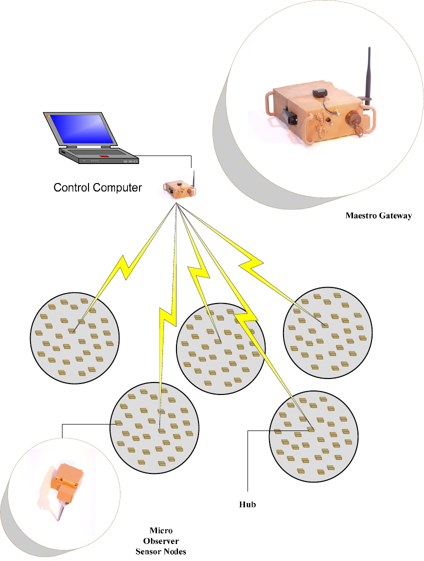
The MicroObserver System is a wireless three-tiered hub and spoke network consisting of
sensors, hubs and remote gateways. The system hardware is homogenous, meaning any node
can function as either a sensor, or a hub/sensor. There are no differences in either hardware
or software of these nodes. Sensors are deployed in a pattern best suited to complete the
mission objectives. The wireless connection is automatic and hubs are selected by the
system based on their ability to communicate with all of the sensors in their area and the
gateway. For larger areas, multiple hubs will be selected by the system. To enhance the
energy management feature on the production system, hubs will rotate automatically within
an area when the network is reformed.
Figure 1 shows the basic system connectivity with the Gateway, Sensors and Hub/Sensors.
5
Figure 1
System Connectivity
6
3 System Components
The MicroObserver system consists of two (2) primary pieces of hardware, the
MicroObserver Sensor Node, MO-1045, and the Maestro Gateway, M-100.
MicroObserver Sensor Nodes have two primary functions, to detect intruders and
communicate with the network. The sensors employ seismic transducers to detect both
dismounted personnel and vehicles (Vehicle Detection & Classification will be integrated in
2Q 2007). Seismic activity is measured and evaluated at the sensor with potential valid
detections sent to the hub via a 2.4 GHz wireless connection which then relays the
information wirelessly to the Maestro Gateway.
The Maestro Gateway is the wireless communications bridge between the sensor field and
the user’s C4I System. Potential detections received from the sensors are evaluated at the
gateway and, if validated, are passed to the C4I system via either Ethernet or RS-232 (RS-
232 will be integrated in the future).
Detections are validated at the Maestro Gateway through the use of a tracker. The tracker is
a unique software feature that, with correlated detections on 3 separate nodes, will form a
track indicating the direction, speed and time of a potential threat. When vehicle detection is
added in 2007 production, the threat will further be identified as either a person or a light or
heavy vehicle.
4 System Operation
4.1 Sensor Start-up Procedure & Deployment
The MicroObserver sensors were designed for ease of set-up and deployment. The nodes are
powered by three (3) COTS AA, alkaline or Lithium non-rechargeable batteries.
MicroObserver will not operate properly with rechargeable batteries. Batteries are
installed by opening the small door located on the long side of the sensor node (side adjacent
to the threaded mount for the spike). It may be necessary to gently pry open the door with
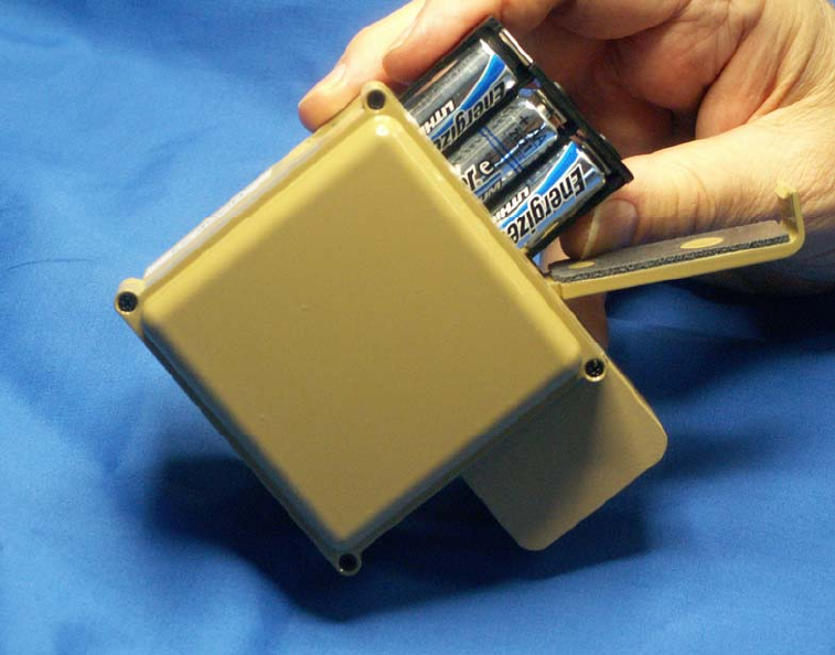
the tip of a ground spike. Batteries are installed directly into a battery holder with the + and
– terminals as depicted on the holder. The holder is keyed such that it will allow only the
proper orientation of the battery holder when it is installed into the sensor, as shown in
Figure 2.
7
Figure 2 Inserting Battery Holder Into Node
Once the batteries are installed the cover door is snapped shut, and the 4” stainless steel
ground spike is installed by screwing it onto the bottom of the sensor. Hand tighten the
spike to the sensor. Do not over tighten, and do not use a wrench. Ensure the spikes are
firmly seated before placing the sensor in the ground.
The sensor is activated by pushing the ON/OFF button located in a cut-out on the bottom of
the unit as shown in Figure 3. Next to the ON/OFF button is a LED indicator light.

8
Figure 3 Node Turn On/Off
• To turn on the sensor, push and firmly hold the button for three (3) seconds. The
LED light will illuminate a constant color.
• As a visual check to see if the unit is on, pushing the ON/OFF button for less than one
(1) second will result in a steady LED indicator.
• To turn off the sensor, hold the button down for three (3) seconds. The LED indicator
will display a steady light until the button is released.
• As a visual check to see if the unit is off, pushing the ON/OFF button for less than
one (1) second will flash a single light.
Sensors are deployed by turning the unit on and placing the unit, spike first, into the ground.
To achieve the best detection results, the bevel of the spike should be pushed into the ground.
Once placement has been completed, quickly walk away from the unit.
Once a sensor is turned on, it will go through GPS acquisition (approximately 60 seconds).
Twenty seconds after a sensor is turned on, background noise calibration begins
(approximately 90 seconds).
NOTE: Because the sensors must acquire GPS and go through the background noise
check, it is important to turn the sensors on only when you are ready to place them in
the ground.
4.1.1 Sensor Deployment Patterns
While there are a variety mission objectives, they generally fall into two basic types of sensor
deployment patterns, Area / Perimeter monitoring and Road / Trail Surveillance.
9
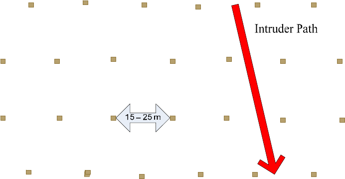
Area monitoring (Area and perimeter) is typically thought in terms of Force Protection or
Fixed Asset protection missions. It is best accomplished by deploying layers of sensor rows
across the area to be monitored. Deploying a number of sensors allows for sensor
redundancy in a given area and gives a higher system Probability of Detection (Pd), as well as
providing the necessary number of detections to form a valid track. The sensors are arranged
to make the suspected threat walk past at least 4 sensors regardless of the path taken through
the area.
Figure 4 below shows a typical sensor deployment pattern for perimeter area or choke point
monitoring.
Figure 4 Perimeter Monitoring
Road / Trail Surveillance is the other type of deployment scenario. Monitoring a suspected
area of activity, high resolution camera cueing and perishable intelligence gathering are the
typical missions for this type of deployment. Sensors need to be deployed in the manner best
suited to give the highest Pd and provide information for the tracker. For Road and Trail
Surveillance, alternating sensors along each side provides the best results

10
Figure 5 Road and Trail Monitoring
4.1.2 Detection Range
Detection range varies with soil type and conditions. Generally speaking, clay is better than
sand as a transmitter of seismic signals since loose material (e.g. leaf debris, freshly plowed
or muddy soil) does not transmit as well as dry, hard packed soil. The stated detection range
is 0-30 meters. We have measured very good performance at 7.5 meters across a number of
soil types.
4.2 Maestro Gateway Start-up and Deployment
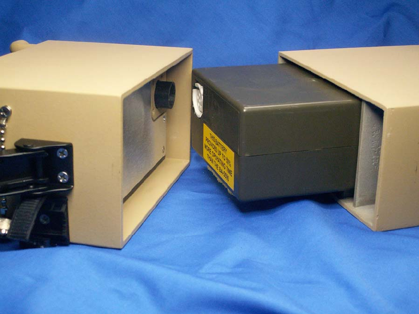
The gateway is powered by a COTS 12V, 22 amp-hr non-rechargeable battery. The gateway
battery has an estimated life of 21 days between battery change-outs. To remove the battery,
unlatch the latches located on the sides of the unit and remove the back cover. Disconnect
the battery at the quick disconnect junction and remove from the unit by gently pulling the
battery away from the front portion of the enclosure. To reinstall, repeat the above steps in
reverse order, taking care to properly orient the connector on the battery with the connector
on the rear of the enclosure. Then re-install the battery cover and secure with the latches on
the sides of the unit. Figure 6 below shows the gateway, battery, and cover.
11
Figure 6 Gateway with Battery and Cover
If not attached already, attach the 7.75” 5 dBi radio antenna to the marked “radio” antenna
connector on side of the gateway. Attach the marked GPS antenna to the marked GPS
antenna port on front of the gateway. Do not over tighten the connectors.
The Maestro gateway is activated via a toggle switch located on the front of the unit.
Turning the switch to the ON position will result in a red LED indicator on the front of the
unit. The gateway should acquire GPS coordinates in approximately 60 seconds.
Connection to the control terminal computer is accomplished via an Ethernet cross-over
cable or by a RS-232 serial cable [RS-232 is a future feature]. Both connections are clearly
marked on the front of the gateway. Once the GPS coordinates have been acquired, the
gateway is ready to operate.
4.3 Operator Terminal
Connect the Ethernet cross over (equipped with RJ45 connectors) to the appropriate port of
the control computer. Power up the computer as you normally would. Start the Operator
Terminal software. For the initial start up, the computer IP address will need to be set to
communicate with the gateway.
12
• On the computer, open Control Panel from the Windows Start Menu.
• Open Network and Internet connections
• Open Network Connections
• Right Click Local Area Connections
• Open Proprieties
• Using the pull down menu, locate and highlight Internet Protocol (TCP/IP)
• Click on Proprieties
• Select the button “Use the following IP address”
• Under IP address type in 192.168.1.1
• Click on OK
• Click on Close.
The control computer is now able to communicate with the gateway. To check the IP
address, open up the command prompt from the Microsoft Windows Start menu, All
Programs; Accessories, Command Prompt C:\. At the C prompt, type: ipconfig and then
press enter.
To verify connectivity to the gateway, type “ping 192.168.1.2”, and then press enter. The
system will go through the communication check protocol three times. If there is a
communication issue, a fault message will be displayed. If there is a fault message, check
the cable connections into both the computer and the gateway. Then check the IP address by
using the above procedure.
[Insert pictures of both ipconfig and ping.]
[
NOTE: The Control Computer and gateway are configured with fixed I.P. addresses. It is
recommended that they be connected via a private LAN connection (crossover cable). If
connected to any other LAN, that system must be capable of accepting the fixed I.P.
addresses of the Control Computer and gateway in order to work properly.
Syncing the Network to the Gateway (Pre-Production Release Only)
The final step before coalescing the pre-production release of MicroObserver network is to
send a sync pulse from the gateway to the sensor network. [This step will be eliminated
with the production versions of the gateway.] Double click the “MSS sync Shortcut” loaded
on the desktop display of the Control Computer. Wait 10 seconds and repeat.
4.4 Coalescing a Wireless Sensor Network
From the top tab menu on the MicroObserver Operator Terminal, select Network. Highlight
and single click “Coalesce.” From this point, the system will automatically go through the
start-up process, working to optimize communications between the sensors, hubs and the
gateway. The network will take approximately 60 seconds to form.
13
On the lower right corner of the GUI there is a Network State message displayed. The
message may display the following circumstances:
RESET: When the network is first brought up or the user has initiated a
network reset using either the RESET or FORCED RESET commands
COALESCING When the network is forming
OPERATIONAL When the network has formed and is operating in normal conditions
UNKNOWN The operator terminal has lost communication with the gateway.
For normal operation, the Network State message will go from Reset, to Coalescing to
Operational.
4.5 Redeployment of Sensors
The MicroObserver System was designed to meet a number of mission criteria. The sensors
can be picked up and redeployed with out any changes to the hardware or software. To
redeploy a field of sensors, or to replace batteries during an extended test; the procedure is as
follows:
• If the system is in “Operational” state, click on the “Network” tab of the Operator
Terminal, then select and click on the “Reset” option. A confirmation dialogue will
ask to confirm the Reset selection. Click on “Yes”.
• At this time the sensors can be retrieved.
• Power the sensors OFF.
• (Replace batteries if needed)
• Power on, deploy, and start the system as mentioned previously in 4.1
4.6 Resetting and Re-coalescing the Network.
Especially with pre-production units, it may be necessary to reset and re-coalesce the
network from time to time. Follow the following procedure to reset the system.
From the Operator Terminal
• Click on “Network” tab, click on “Reset”, answer “Yes’ to query, (wait 5 seconds)
• Click on “Network” tab, click on “Forced Reset”, answer “Yes” to query, (wait 15
seconds)
• Click on “Network” tab, click on “Coalesce”, verify that Network State shows
“Coalescing”
• Wait approx. 60 seconds, verify that Network State shows “Operational”
14
4.7 Shutting Down the Network
The network shut down procedure is:
• Turn off the gateway
• Close the operator terminal and shut down the computer
• Pick up and power off the nodes.
5 Trouble Shooting Guide
Network State Unknown
With pre-production release hardware and GUI system, the network may occasionally go into
Network State: Unknown status. This is a very infrequent condition that can be dealt with in
the following manner.
• Close the operator terminal program on the control computer.
• Power cycle the gateway (turn power off, wait 5 seconds, turn power on)
• Once the gateway has acquired GPS, restart the Operator Terminal program.
• Reset the system as mentioned in Section 4.6. Do this even if the Network State says
it is in the “Reset” state.
• Resynchronize and Restart the system as if it were an initial start up.
If nodes are not joining the network after this process, see the section below on “Some or all
of the Nodes do not join the network”
Sensors will not power up
• Check to see if the batteries are installed correctly
• Change batteries
• When pressing the ON/OFF button, reposition your finger to a better angle.
Sensors do not appear to be detecting
From time to time, when watching the GUI, a sensor may fail to report what you feel should
have been a detection. There are multiple reasons for this:
• Multiple detections squashed one of the detection displays at the Operator
Terminal/GUI. (typically a track will form even if the display doesn’t show).
•
Gateway light does not appear to be on
• Reposition gateway out of the sunlight.
• Check to see if battery is plugged in.
Nodes shut off by themselves (pre-production units only)
There are instances where the nodes have shut themselves off. The most common causes are:
• The unit was not turned on (easy to do in a hurry)
15
• Dead batteries.
• Physically dropping the sensors causes a momentary power interrupt. Power cycling
the sensor will remedy this.
Some or all of the Nodes do not join the network
• In especially challenging RF conditions, there may be instances where not all of the
sensors will join the network. The best solution at this point is to follow the reset &
re-coalesce procedure listed in section 4.6
If any problem persists after following these instructions, call the factory for trouble shooting
assistance.