SignalFire Telemetry GWDIN DIN Mount Gateway User Manual
SignalFire Telemetry, Inc. DIN Mount Gateway
User Manual.pdf
Rev 1.3 SignalFire Telemetry
1
Interface Manual
DIN Gateway
SignalFire Part Numbers: GW-DIN, GW-DIN-STATICIP
The SignalFire DIN Gateway has the following features:
- RS485 connection to Modbus master device
- Optional Modbus-TCP Ethernet gateway module
- Wide range DC power input. 6 to 36VDC
- Two open collector digital outputs
- DIN rail mount
- Collects and caches Modbus data from all SignalFire remote nodes
- Provides configuration and status registers for remote configuration and status monitoring
- RP-SMA antenna port for connection to external 900MHz antenna
- Stores up to 4700 register values from any combination of remote nodes
- Supports transparent Modbus mode
- Internal Remote Shut Down (RSD) logic control option
- Slave register re-mapping
- Remote configuration of SignalFire devices through an Ethernet gateway connection
- Remote sensor configuration (PACTware and RadarMaster)
- Radio is FCC and IC approved
- Class 1 Division 2 Area certification pending

Rev 1.3 SignalFire Telemetry
2
Connections and Components
DIN Gateway Connections
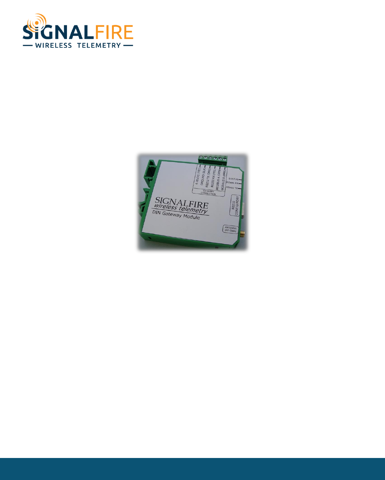
The DIN Gateway has a 6-position pluggable terminal block for power and serial communications. The
connections are as follows:
Terminal Name
Connection
6-36VDC (RED)
Positive Power (6 to 36 VDC)
GROUND (BLK)
Ground
RS232 TX (ORG)
RS-232 Debug TX, 9600 Baud (Only used with Ethernet GW module)
RS232 RX (YEL)
MODBUS A (GRN)
RS-232 Debug RX, 9600 Baud (Only used with Ethernet GW module)
RS-485 “A”, 9600 Baud
MODBUS B (BRN)
RS-485 “B”, 9600 Baud
In addition, a RS232 DB9 port is available for connection to the SignalFire Toolkit for configuration and
diagnostics.
Gateway Hardware revision 2 also has a 3-position pluggable terminal block with two open collector
digital outputs for signaling or alarm functions. Each output is rated to 30VDC and 1 Amp.
Optional Ethernet Gateway Connections
When used with a SignalFire Ethernet Gateway module, the 6-potition screw terminal block should be
connected to the color coded “Gateway Stick Connection” connector on the Ethernet Gateway. Power
can be supplied either to the Power Input terminals on the Ethernet Gateway or via power over
Ethernet (PoE).
NOTE: when used with an Ethernet Gateway module the DB9 on the Ethernet module must be used for
ToolKit access.

Rev 1.3 SignalFire Telemetry
3
Status LEDs
The DIN Gateway has three LED Available for field diagnostics. The RS485 TX/RX LEDs will blink in
response to RS485 traffic, the status LED is described below.
STATUS LED
Description
Slow Flash (3 second pause)
System is running and in communication with radio network
Fast Flash (0.5 second pause)
System is running but no network found
Solid On
System Fault needs service or rescue bootload
Operation
The DIN Gateway supports all remote SignalFire nodes making all remote sensor data
available in Modbus format.
The register data from remote sensor nodes is available by requesting the remote node’s Modbus
slave ID and register address from that node’s register map. The gateway will respond with the most
recent copy of the data from the remote node. The gateway will automatically time-out data from a
remote node it stops receiving data for.
If the remote node is a Modbus-Stick additional features are supported.
Remote Modbus Sticks and Sentinel-Modbus (non-sleeping radio only) Nodes
Remote nodes that have been pre-configured forward their set of registers to the Modbus gateway
on a pre-defined schedule (1 minute to 5 minutes is typical). The register data is then buffered in the
gateway and is available to be read by the RTU at any time.
If a Modbus request is received by the gateway for a Modbus ID and address for which buffered data
does not exist, but the Modbus ID is known, the Modbus request will be forwarded to the remote
Modbus node over the SignalFire network. The response is returned to the RTU.
If a request for multiple registers is issued by the RTU, and if the gateway does not have all registered
data buffered, an exception will be returned. The system will not combine buffered and transparent
data within a single Modbus response.

Rev 1.3 SignalFire Telemetry
4
Remote Modbus Stick Node Re-Scan
It is possible to cause a remote Modbus Stick to re-scan for attached Modbus devices by writing to
one of the gateway’s configuration registers. This is useful to discover a Modbus device that is added
to an existing Modbus node. The scan may be initiated by one of the two methods. First, if the radio
address of the Modbus Stick is known, writing this address to gateway register 3000 will result in a
scan. Second, if the Modbus ID of one of the already registered devices attached to a Modbus Stick is
known, a scan will be started by writing the ID to gateway register 3002.
Rev 1.3 SignalFire Telemetry
5
Setup
The DIN Gateway requires an initial configuration over the debug port. The supplied
SignalFire Toolkit PC application will be used to configure the device over the serial port.
The following item must be configured:
- Radio Network and Group Selection
NOTE: If used with an Ethernet Gateway module the DB9 on the Ethernet module must be used for
ToolKit access.
Using the SignalFire Toolkit
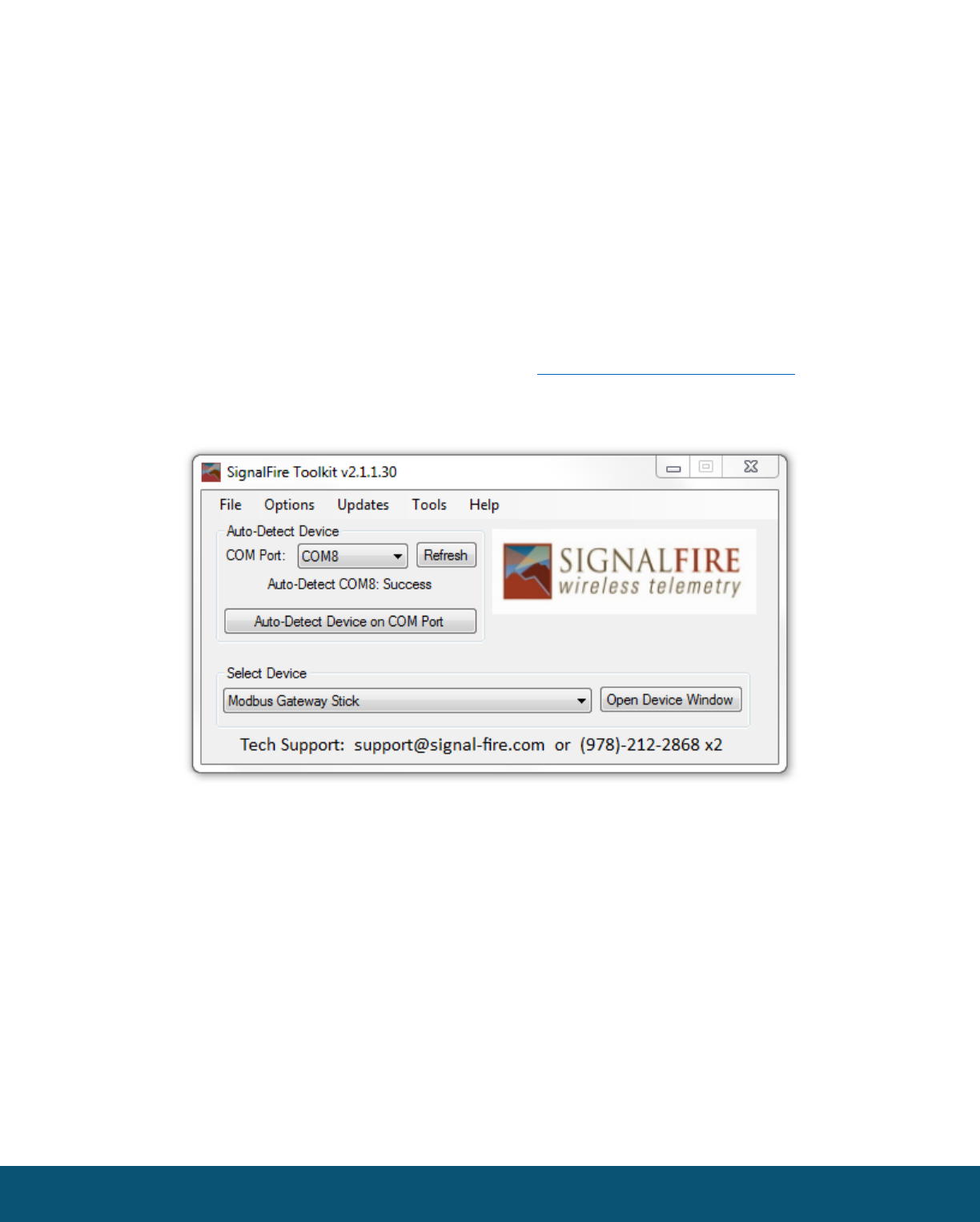
The SignalFire Toolkit application can be downloaded at www.signal-fire.com/customer. After
installation, launch the software and the main toolkit window will open:
Select the COM port associated with the DIN Gateway and click “Auto-Detect Device on COM Port.”
This will open the device configuration window, where all device settings can be configured.
Rev 1.3 SignalFire Telemetry
6
Network Setting
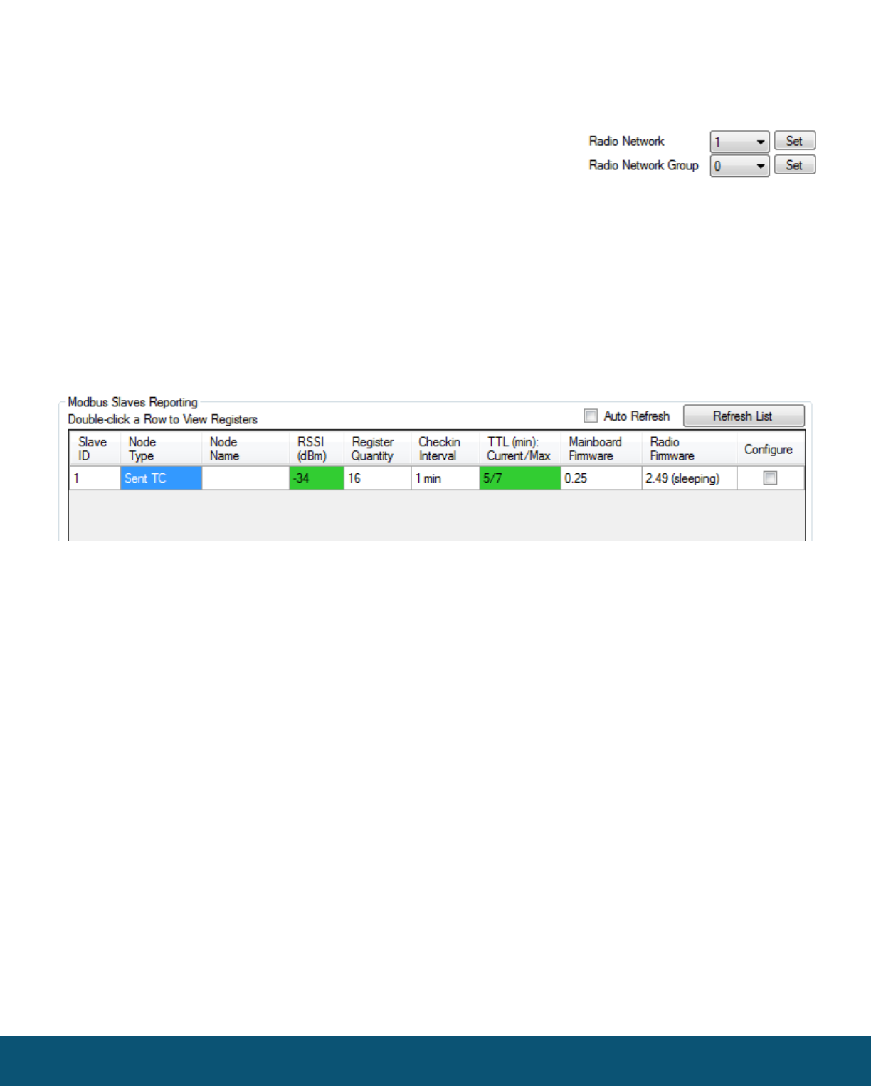
The network address can be used to create separate networks using multiple gateways (that are in
close proximity with one another). The network is set using the SignalFire Toolkit. The Network
Group setting is used when more than 8 networks are needed. Both
the network and network group must match those of other nodes
for nodes to communicate.
Checking Remote Nodes
If one or more remote nodes are configured with the correct network settings they will send their data
to the gateway. Clicking Refresh List will populate the list with all connected remote nodes. Double
clicking on one of the nodes in the list will bring up additional detail including the register data from
the remote node.
The gateway displays the node type, node name (is one is programmed into the need), RSSI signal strength,
programmed node check-in interval, the Time To Live (TTL), and the nodes radio and main firmware versions.
The RSSI and TTL values are color coded (Green, yellow, orange, red) to indicate relative link quality of a node.
The ‘TTL current’ indicates the number of minutes remaining until the node will be timed out of the gateway if
no updates are received. The ‘TTL max’ indicates the maximum TTL for that node, the ‘TTL current’ will be set
to the ‘TTL Max’ each time an update is received from that node.

Rev 1.3 SignalFire Telemetry
7
Modbus Gateway Register Map
The SignalFire Modbus Gateway by default is assigned Modbus Slave ID number 247. Only the
Gateway status/configuration registers are read at this address. All remote node registers are read
from the slave ID and register address of the remote node, unless slave register remapping used.
Gateway Configuration and Status Messages
Boolean Registers – These are 1-bit coil registers. They can only be written to by Modbus opcode
0x05 (Write Single Coil). To perform the following resets, write a 0xFF00 to the respective coil. Writing
0x0000 to a coil has no effect.
Register
Number
Register
Address
(Offset)
Description
00001
0000
Resets the gateway and radio
00002
0001
Resets the radio leaving the gateway on
00003
0002
Resets all counters to zero (See Read Only Registers 2026-2031)
Read/Write Registers – These are 16-bit read/write registers. They can be written to by Modbus
opcode 0x06 or 0x10 (Write Single and Multiple Registers, respectively) and can be read with Modbus
opcode 0x03 or 0x04 (Read Discrete Input and Holding Registers, respectively). The first three registers
are identical to the previous three write coils and behave similarly. They will be read as 0x0000 and
can be triggered by writing 0xFF00 to them. The remaining must be written with 16-bit values in the
range specified in the table below.
Register
Number
Register
Address
(Offset)
Description
41001
1000
Resets the gateway and radio
41002
1001
Resets the radio leaving the gateway on
41003
1002
Resets all GW status counters to zero (See Read Only Registers 2026-2031)

Rev 1.3 SignalFire Telemetry
8
Read Only Registers – These are 16-bit read only registers. They can be read with Modbus opcode
0x03 or 0x04 (Read Discrete Input and Holding Registers, respectively). The register map can be
found on the next page.
If the gateway has a large total number of registers approaching 4700, register 2008 should be
monitored to ensure that free registers are available before adding a new node.
Register
Number
Register
Address
(Offset)
Description
42001
2000
Upper 16 bits of SFTS GW node address (the radio ID)
42002
2001
Lower 16 bits of SFTS GW node address (the radio ID)
42003
2002
Upper 16 bits of Radio Firmware version number
42004
2003
Lower 16 bits of Radio Firmware version number
42005
2004
Upper 16 bits of gateway firmware version number
42006
2005
Lower 16 bits of gateway firmware version number
42007
2006
Number of slave nodes that data is cached for this gateway
42008
2007
Total number of registers allocated to slave devices
42009
2008
Total number of free registers available for slave devices
42010
2009
Bitmask for active slave IDs 15-0 (LSB is 0)
42011
2010
Bitmask for active slave IDs 31-16 (LSB is 16)
42012
2011
Bitmask for active slave IDs 47-32 (LSB is 32)
42013
2012
Bitmask for active slave IDs 63-48 (LSB is 48)
42014
2013
Bitmask for active slave IDs 79-64 (LSB is 64)
42015
2014
Bitmask for active slave IDs 95-80 (LSB is 80)
42016
2015
Bitmask for active slave IDs 111-96 (LSB is 96)
42017
2016
Bitmask for active slave IDs 127-112 (LSB is 112)
42018
2017
Bitmask for active slave IDs 143-128 (LSB is 128)
42019
2018
Bitmask for active slave IDs 159-144 (LSB is 144)
42020
2019
Bitmask for active slave IDs 175-160 (LSB is 160)
42021
2020
Bitmask for active slave IDs 191-176 (LSB is 176)
42022
2021
Bitmask for active slave IDs 207-192 (LSB is 192)
42023
2022
Bitmask for active slave IDs 223-208 (LSB is 208)
42024
2023
Bitmask for active slave IDs 239-224 (LSB is 224)
42025
2024
Bitmask for active slave IDs 255-240 (LSB is 240)
42026
2025
Gateway power supply voltage in mV
42027
2026
Radio packets received count
42028
2027
Radio packets sent count
42029
2028
RS-485 messages received count
42030
2029
RS-485 messages sent count
42031
2030
Total Modbus errors from master and slaves
42032
2031
Modbus exceptions from slave nodes
42033
2032
Radio packets received/transmitted per minute. Recommended to be less than 60
42034
2033
Radio packets per minute alert. 0 if packets/min <= 60, 1 if packets/min > 60
42101
2100
Address test register. Always returns 2100
42102
2101
Address test register. Always returns 2101
42103
2102
Address test register. Always returns 2102
Rev 1.3 SignalFire Telemetry
9
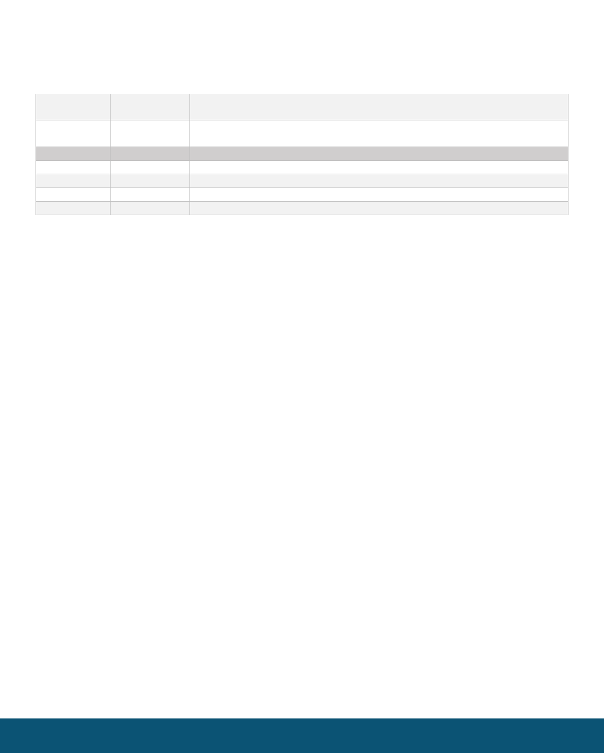
43001
3000
Write the radio address of a Modbus Stick node to this register to cause that
Modbus Stick to perform a scan for attached Modbus sensors
43004
3003
Write Modbus ID for a Modbus Client node to this register to cause that remote
node to perform a scan for attached Modbus sensors
44002
4001
Status of Slave ID 1:Returns 1 if Slave is present and 0 if not present
44003
4002
Status of Slave ID 2:Returns 1 if Slave is present and 0 if not present
…
…
…
44241
4240
Status of Slave ID 240:Returns 1 if Slave is present and 0 if not present

Rev 1.3 SignalFire Telemetry
10
Firmware Upgrades
Firmware updates for both the gateway (ARM) and the built-in radio are possible over the
RS-232 debug interface using the SignalFire Toolkit, or over a remote TCP connection if an
Ethernet Gateway module is used.
Gateway (ARM) Firmware update steps
1 Open the SignalFire Toolkit application.
2 Open the correct COM port connected to the RS-232 port of the gateway.
3 Go to the Update menu and select Update Gateway Firmware.
4 The latest gateway firmware file will be selected by default.
5 Click Start Upgrade.
Gateway Radio Firmware update steps:
1 Open the SignalFire Toolkit application.
2 Open the correct COM port connected to the RS-232 port of the gateway.
3 Go to the Update menu and select Update Radio Firmware.
4 The latest radio firmware file will be selected by default.
5 Click Start Upgrade.
Rescue Gateway (ARM) Bootload
If in the process of a firmware update there is a power failure or other communications failure it may
be necessary to do a “rescue bootload.” If the base LED is solid on and/or the Toolkit is unable to
communicate with the Gateway the following process is necessary.
1 Remove DC power to the Gateway.
2 Open the SignalFire Toolkit application.
3 Open the correct COM port connected to the RS-232 port of the gateway.
4 Go to the Update menu and select Update Gateway Firmware.
5 The latest gateway firmware file will be selectable by default.
6 Click Start Upgrade.
7 Now re-connect the DC power to the gateway. The firmware update process should start. If the
firmware update does not start remove power for at least 10 seconds and re-try.
Rev 1.3 SignalFire Telemetry
11
Remote Shutdown (RSD) and Local Digital Output Control
The SignalFire Gateway supports Internal Logic Control capability which enables the
Gateway to control output relays on SignalFire RSD sticks as well as the two digital outputs
local to the Gateway
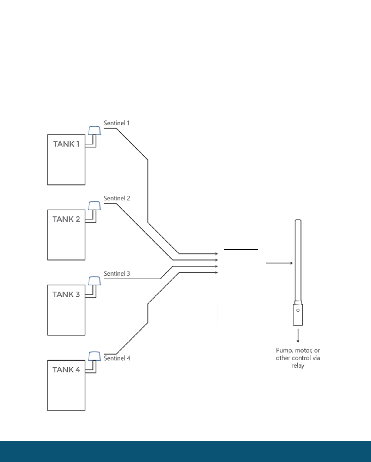
The SignalFire Gateway Stick receives data from multiple remote nodes. It can use the data from those
remote nodes to set the relay output on one or more remote RSD sticks. An example of the topology
is shown in the following figure:
RSD Stick
DIN
GATEWAY
Rev 1.3 SignalFire Telemetry
12
RSD Configuration
From the Gateway configuration window within the SignalFire Toolkit, go to the Settings
menu and select Remote Shutdown Settings. This will open the RSD configuration window.
Source Node Section
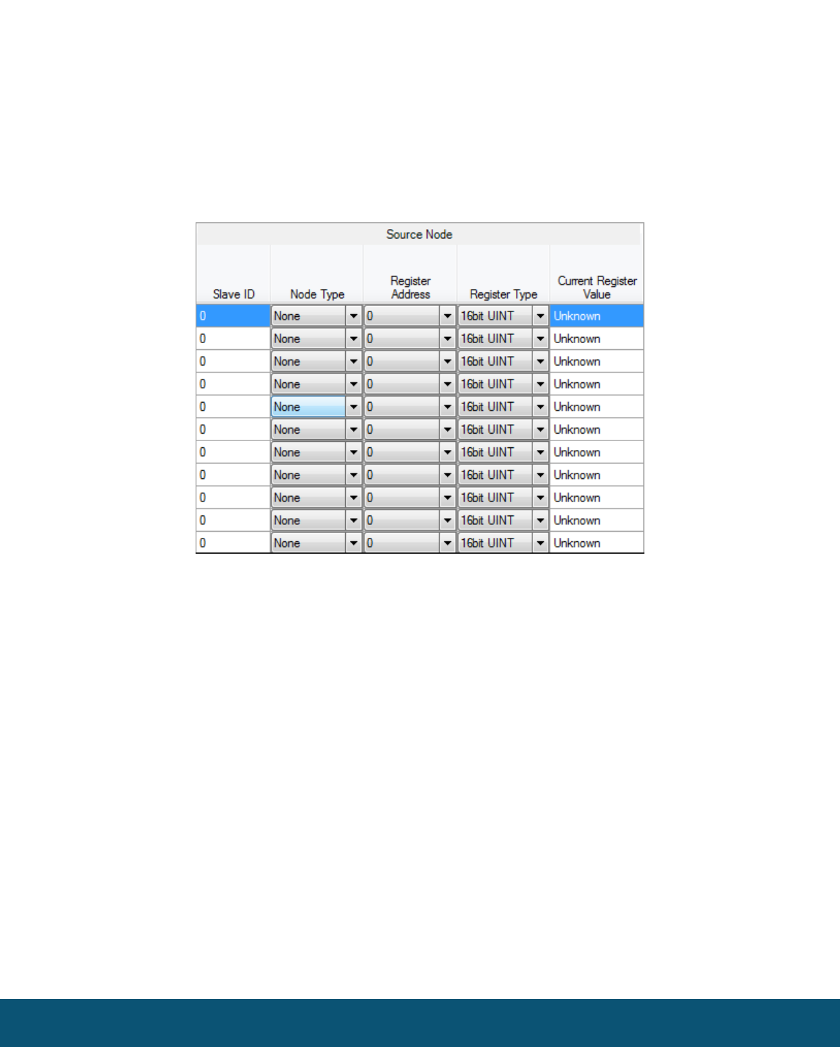
The source node section is used to select the source register for the logic rule.
Slave ID – The Modbus Slave ID of the remote source node.
Node Type – Drop-down list of standard SignalFire remote nodes. Select the type of remote node
here, or select Custom for manual data entry.
Register Address – Select the register address for the data to use for the logic, or manually enter the
register address if Custom was select for the node type.
Register Type – The correct register data type will automatically be selected unless Custom is used. If
using a custom register address, select the correct data type here.
Current Register Value – Displays the value of the selected source data register. Clicking the Update
button will refresh this value.
Rev 1.3 SignalFire Telemetry
13
Relay Control Logic Section
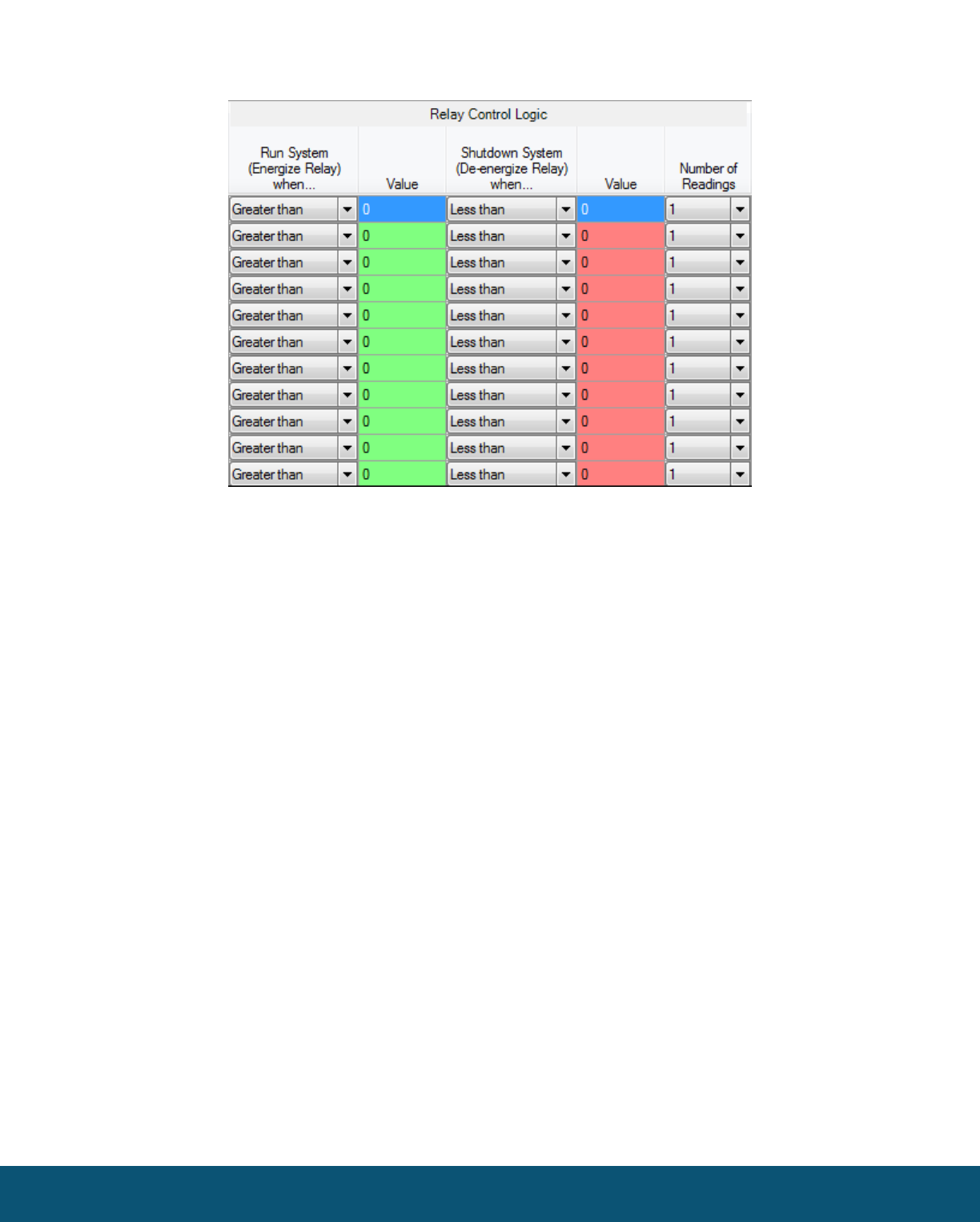
The relay control logic section is used to set the trigger thresholds for the selected source data
register.
Run System (Energize Relay)
– Select the logic operand to use for the “energize” logic evaluation.
Value
– The value that the relay will be energized. Note that the energized state is the normal
“operating” state of the relay.
Shutdown System (De-Energize Relay)
– The logic operand to use for the “de-energize” logic
evaluation. This will automatically be the opposite of the selection for the energize case. Note that the
de-energized state is the SAFE state of the relay.
Value
– The value that the relay will be de-energized. Note that the de-energize state is the “safe”
state of the relay.
Number of Readings
– This field contains the number of check-in packets that must be received in a
row that are above (or below) the logic threshold for the de-energize condition. This is useful so that a
single (possibly a glitch) reading does not cause a shut-down. The default is 1 where each check-in
will cause the rule to be evaluated and acted on. A single reading that satisfies the run system
(energize) condition will cause the relay to energize.
Rev 1.3 SignalFire Telemetry
14
Destination RSD Stick Section
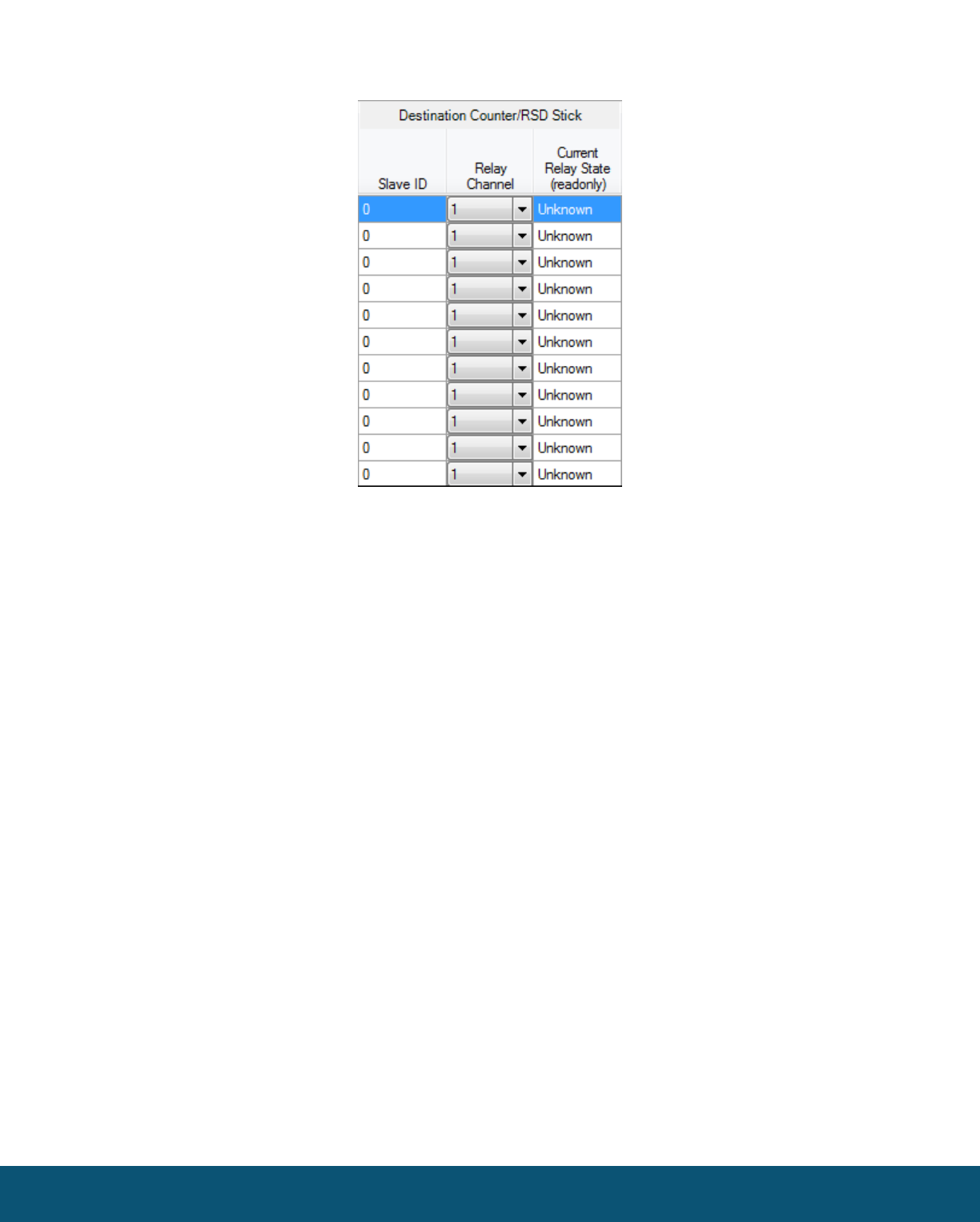
Slave ID
– The Slave ID of the destination RSD Stick, or the slave ID of the Gateway (default 247) for
the local digital outputs.
Relay Channel
– Select the relay or digital output channel to switch
Current Relay State
– Shows the last value of the relay or digital output as reported to the gateway.
Clicking the Update button will refresh this value.
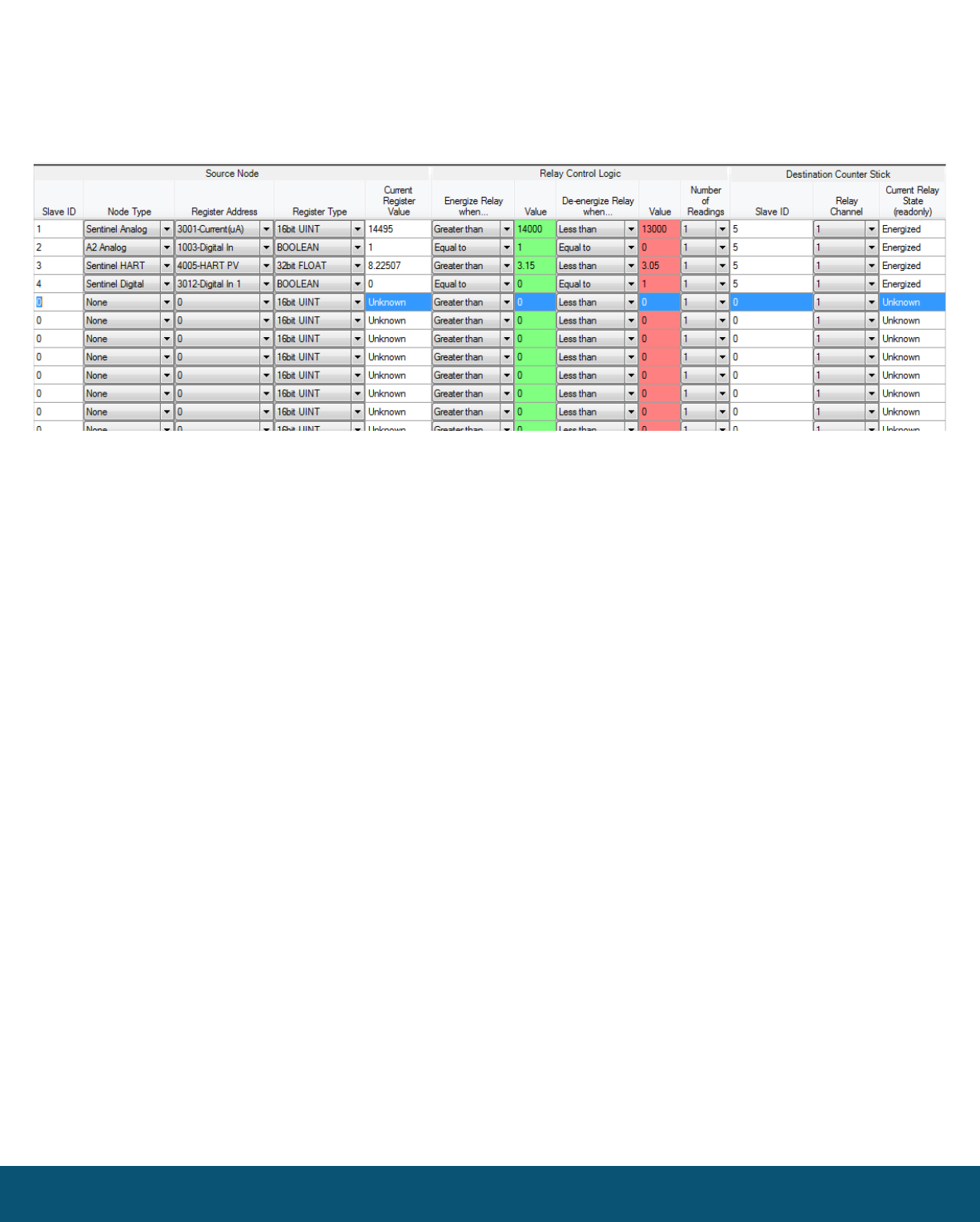
After filling out the table click Write Remote Shutdown Settings to Gateway to store the setting in
the gateway Stick.
Rev 1.3 SignalFire Telemetry
15
Example
Line 1 has been configured with a source data node as a Sentinel-Analog with the loop current (in μA)
as the selected register. The relay will energize when the loop current is above 1400μA (14mA) and
de-energize when the loop current is below 1300μA (13mA). Note that this configuration has a
1000μA (1mA) hysteresis factor.
In this example all 4 source nodes are assigned to the same destination Slave ID and relay channel so
the following statement applies:
If more than one rule is assigned to the same destination RSD Stick (or gateway
output) and relay channel, then all of the rules must meet the energize condition for
the remote relay to be energized.
Alternatively, this means that if any one of the four source node’s logic results in the
“de-energize” condition being true the relay will be de-energized (safe).

Rev 1.3 SignalFire Telemetry
16
Options
There are two check boxes for additional logic options.
Failsafe Enabled
– If this option is selected all rules must have valid data for the relay to be energized.
If one or more of the nodes times-out or does not exist the relay will be de-energized.
If this option is not selected, then a node that is not installed or fails to check in will be ignored and
the relay will be energized using logic only from the units that are active.
Latch De-Energized
– If this option is selected the rules may only de-energize the relay. For the relay
to be energized again a Modbus write from a PLC to the gateway for the destination RSD stick relay
must occur. This is useful if manual intervention is required before the relay is energized after an
event. In the example above, a Modbus coil write to Slave ID 5 relay channel 1 (which is register 1) is
required to energize the relay. See the RSD Stick manual for a detailed register map.
The “Normal” state of the relay or digital output is the un-energized state and this state should be
used to set the controlled system (pump, motor,…) in the “safe” or “off” state.
Rev 1.3 SignalFire Telemetry
17
Slave Register Remapping
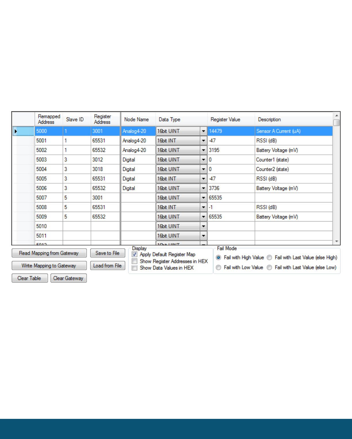
The gateway allows any of the remote register data to be remapped to a single block of
registers available at the Gateway’s slave ID (default is 247). This is useful for collecting a
subset of register data from multiple nodes and making it readable in a single block of registers. Up to
750 registers can be remapped to the gateway’s slave ID starting at register 5000.
To configure the remapping, first select Slave Register Remapping from the Settings dropdown
menu.
Enter the remote slave ID and register address to map to each gateway register and click Write
Mapping to Gateway to remap the register(s).
The Node Name, Data Type, Register Value, and Description fields will automatically be filled in by
the gateway once the mapping is written to the gateway. If the gateway does not have data for a
remapped value it will respond with 0xFFFF, or 0x0000 for the register request, this is configurable
globally with the Fail Mode settings.
In the example above, slave ID 1 is a Sentinel-Analog with has been mapped to have sensor current,
RSSI and battery voltage available at gateway registers 5000 through 5002. Note that slave ID 5 is not
currently reporting data to the gateway so its registers are failing “high.”
Rev 1.3 SignalFire Telemetry
18
Remote Node Configuration
The SignalFire Gateway allows configuration changes to be made to any of the connected
SignalFire remote nodes wirelessly. To use this feature, access to the Gateway debug port is
required. This may be accessed over a TCP/IP network using a SignalFire Ethernet Gateway module, or
by a direct connection to the Gateway RS232 port.
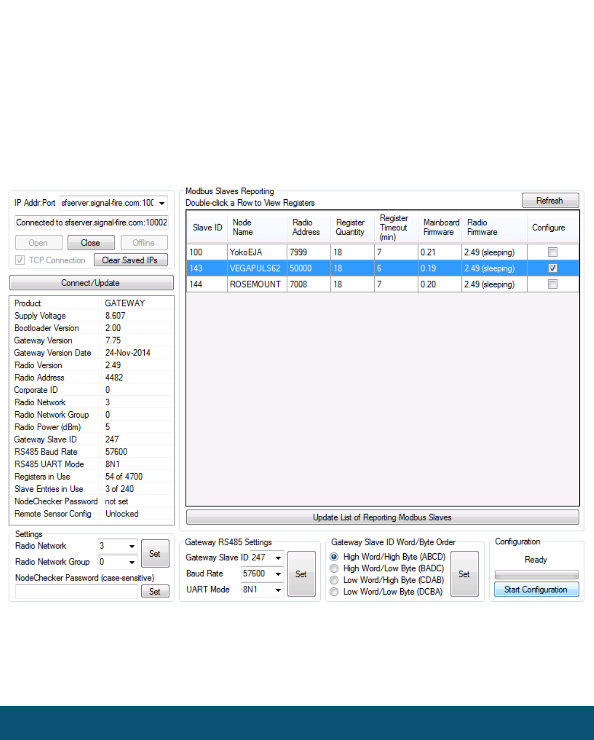
To start a remote configuration session with a remote node, select the check-box next to the node to
configure and click Start Configuration.

Rev 1.3 SignalFire Telemetry
19
If the node has an awake radio the remote configuration session will be ready immediately.
If it is a sleeping node you must wait for the node to either check-in or send a “beacon” so
that it can be commanded into configuration mode. The Sentinel nodes send a beacon
every 2.5 minutes, while all other sleeping nodes send a beacon every 5.5 minutes. When
the node has entered a remote configuration session you will see a message indicating the slave is
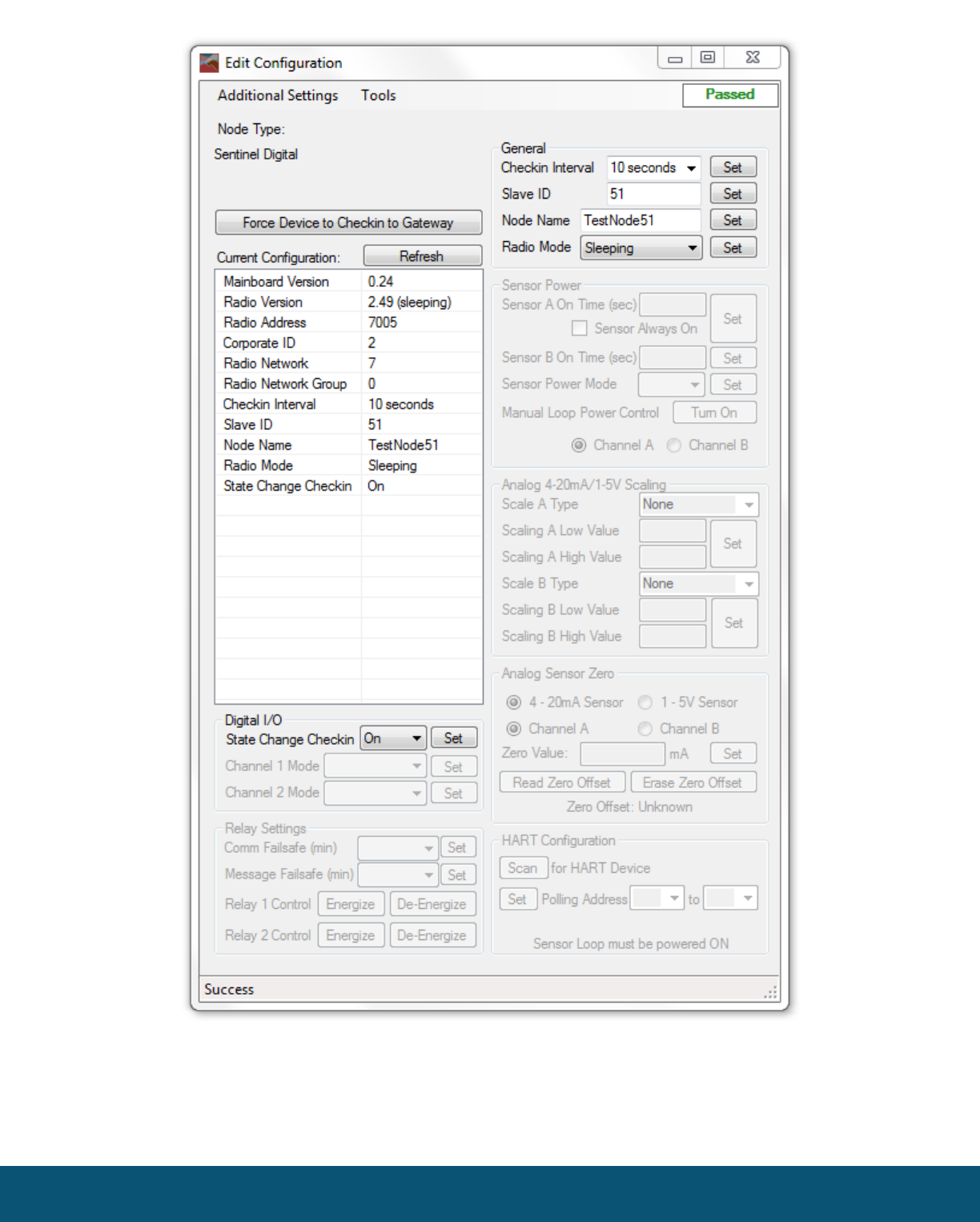
ready. Click Configure to open the configuration window (image on next page).
Make any necessary changes and click the corresponding Set button to save the changes. When
finished with the configuration, close the configuration window and then click the End button in the
Gateway window to end the session. The session will also automatically time-out after 15 minutes of
inactivity and the Node will resume normal operation.
Rev 1.3 SignalFire Telemetry
20
Example Remote Configuration Window

Rev 1.3 SignalFire Telemetry
21
Gateway Event Log
Starting with Gateway Firmware version 7.81 the Gateway keeps an internal log of events.
The event log can be viewed from the gateway window of the ToolKit by selecting ‘View
Gateway Log’ from the Tools menu. The gateway log events such as reboots, remote nodes
joining/timing out, local RSD control events, remote configuration sessions, firmware updates, and
more.
Revision History
Revision
Date
Changes/Updates
1.0
10/02/15
Initial Release for DIN Gateway
1.1
2/26/16
Added FCC/IC certification details
1.2
4/6/16
Added detail for Gateway digital outputs
1.4
4/14/16
Updated IC statements

Rev 1.3 SignalFire Telemetry
22
APPENDIX - FCC and IC Statements
Changes or modifications not expressly approved by SignalFire Telemetry, Inc could void the user’s authority to
operate the equipment.
This device complies with Part 15 of the FCC Rules. Operation is subject to the following two conditions: (1) this device
may not cause harmful interference, and (2) this device must accept any interference received, including interference that
may cause undesired operation.
This equipment has been tested and found to comply with the limits for a Class B digital device, pursuant to Part 15 of the
FCC Rules. These limits are designed to provide reasonable protection against harmful interference in a residential
installation. This equipment generates, uses and can radiate radio frequency energy and, if not installed and used in
accordance with the instructions, may cause harmful interference to radio communications. However, there is no
guarantee that interference will not occur in a particular installation. If this equipment does cause harmful interference to
radio or television reception, which can be determined by turning the equipment off and on, the user is encouraged to try
to correct the interference by one of the following measures:
-- Reorient or relocate the receiving antenna.
-- Increase the separation between the equipment and receiver.
-- Connect the equipment into an outlet on a circuit different from that to which the receiver is connected.
-- Consult the dealer or an experienced radio/TV technician for help.
This device has been designed to operate with the antennas listed below, and having a maximum gain of 5.8 dBi.
Antennas not included in this list or having a gain greater than 5.8 dBi are strictly prohibited for use with this device. The
required antenna impedance is 50 ohms.
San Jose Technology Inc. Model EEH-915
Nearson Model: S467XX-915S
To reduce potential radio interference to other users, the antenna type and its gain should be so chosen that the
equivalent isotropically radiated power (e.i.r.p.) is not more than that permitted for successful communication.
To comply with FCC’s and IC’s RF radiation exposure requirements, the antenna(s) used for this transmitter must be
installed such that a minimum separation distance of 20cm is maintained between the radiator (antenna) & user’s/nearby
person’s body at all times and must not be co-located or operating in conjunction with any other antenna or transmitter.
This device complies with Industry Canada’s licence-exempt RSSs. Operation is subject to the following two conditions:(1)
This device may not cause interference; and (2) This device must accept any interference, including interference that may
cause undesired operation of the device.
Le présent appareil est conforme aux CNR d'Industrie Canada applicables aux appareils radio exempts de licence.
L'exploitation est autorisée aux deux conditions suivantes : (1) l'appareil ne doit pas produire de brouillage, et (2) l'appareil
doit accepter tout brouillage radioélectrique subi, même si le brouillage est susceptible d'en compromettre le
fonctionnement.