Siklu Communication SK-60GTDD-A1 Wireless Ethernet link User Manual User manual
Siklu Communication Ltd. Wireless Ethernet link User manual
UserManual.wiki
>
Siklu Communication
>
SK 60GTDD A1 User Manual
User_manual
Navigation menu
Upload a User Manual
Namespaces
Wiki Guide
HTML
PDF
Info
Views
User Manual
Discussion / Help
Navigation
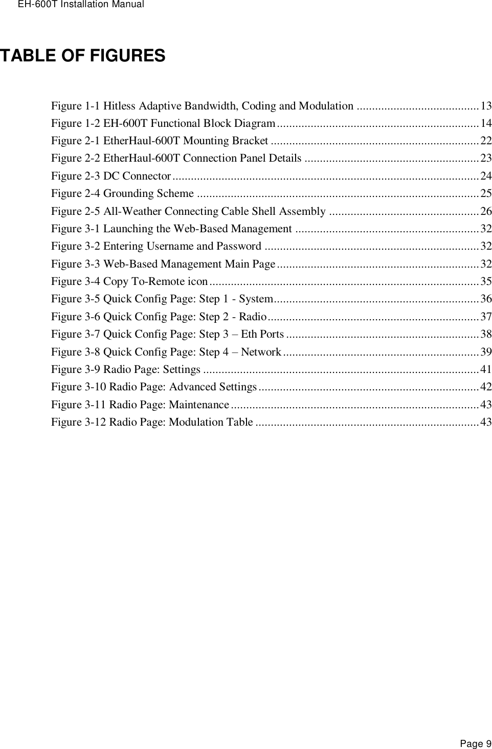
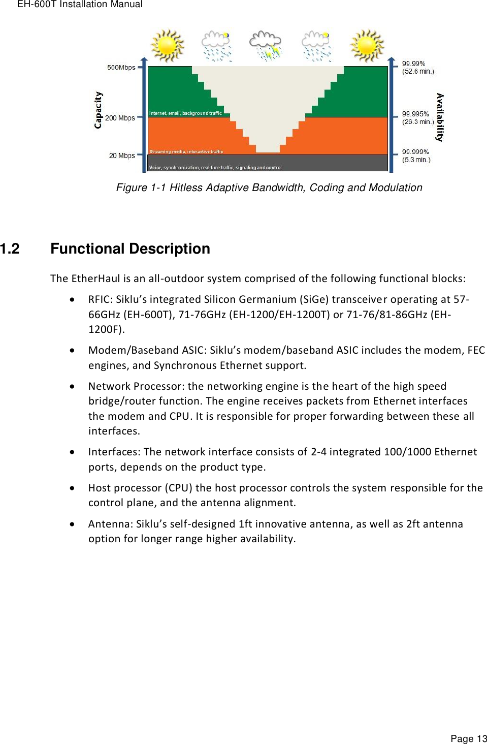
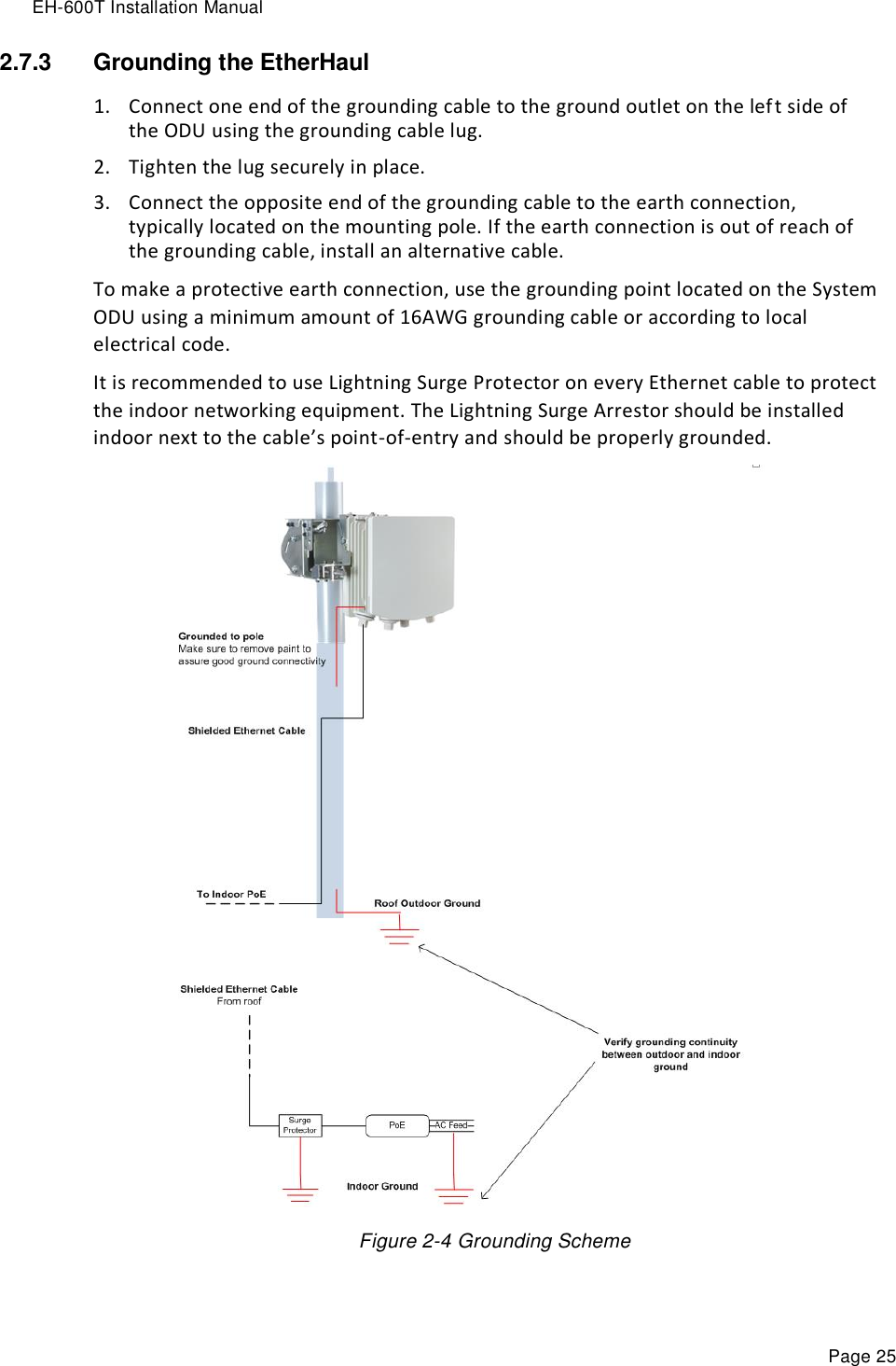
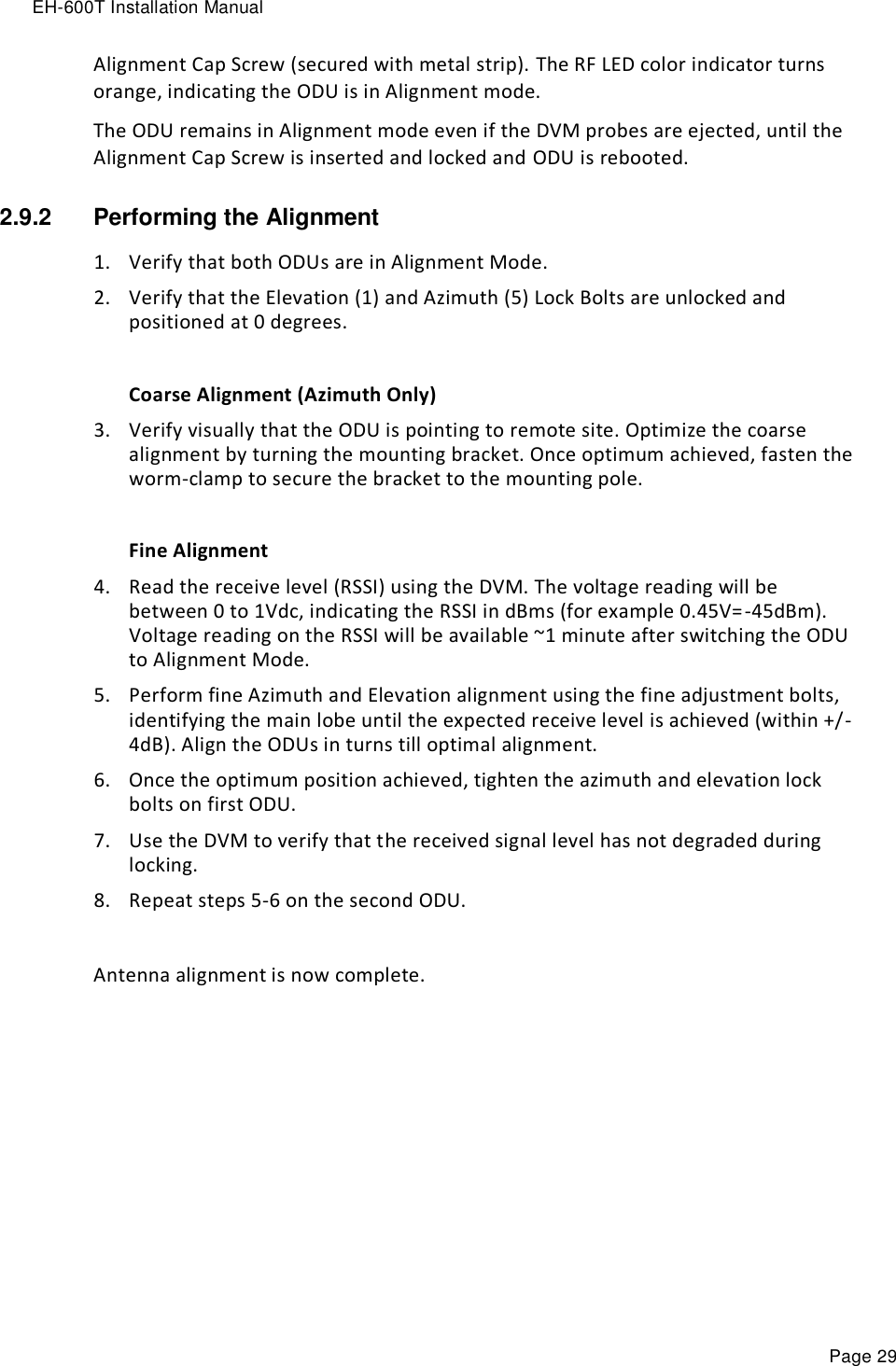
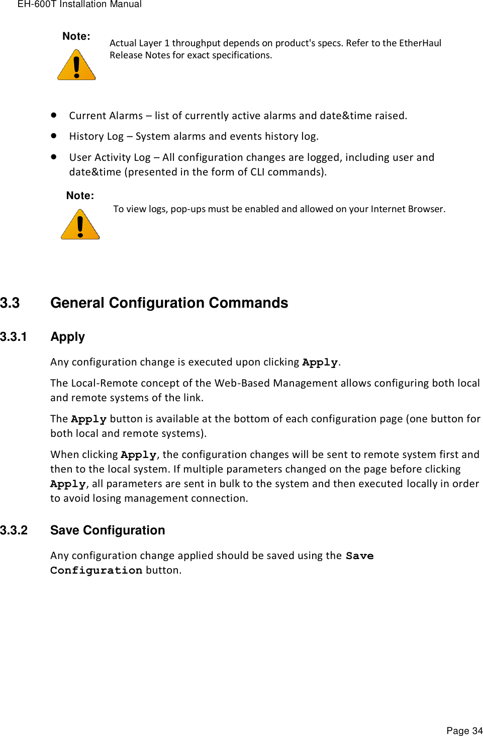
![EH-600T Installation Manual Page 33 3.2 Main Page The Web-Based Management provides link view, presenting both local and remote configuration and monitoring. Although the local and remote systems IP address is identical (default IP address 192.168.0.1), the remote will be available as well as the EtherHaul uses dedicated communication channel for local-remote communication that is not IP-based. It is recommended, however, to assign dedicated IP address for local and remote systems. Note: Depending on your station’s screen size and resolution, you may need to scroll the screen vertically or horizontally in order to view all options for local + remote. Alternatively, you may change the change the Internet’s Browser display distance (Zoom out, using Ctrl+Minus). The Web-Based Management Main page is a read-only page and displays the following information: Link Status – Link up or down (with visual indication) Link Length [m] – link calculated distance between the local and remote systems (air distance) based on propagation time. Tx/Rx frequency [MHz] RSSI [dBm] – Receiver Signal Strength Indicator. Current receive level. CINR [dB] – Carrier to Interference + Noise ratio. Indicates the current radio link’s signal quality. In normal conditions, CINR≥19 indicates a good signal quality. Mode – Current operational mode of the link: o Alignment – Carrier Wave transmission. Used for antenna alignment. No data over the radio link. o Static – Fixed modulation profile. If you select Static, you must select from a list of pre–configured modulation profiles in the Modulation field. o Adaptive – Adaptive Bandwidth, Code, and Modulation. The system will work on the highest modulation profile based on the CINR values of the both sides and will present the current modulation profile. Estimated Throughput [Mbps] – based on the current modulation profile. o For EH-600T (TDD system) – value is aggregated (Half-Duplex).](https://usermanual.wiki/Siklu-Communication/SK-60GTDD-A1/User-Guide-2382352-Page-33.png)
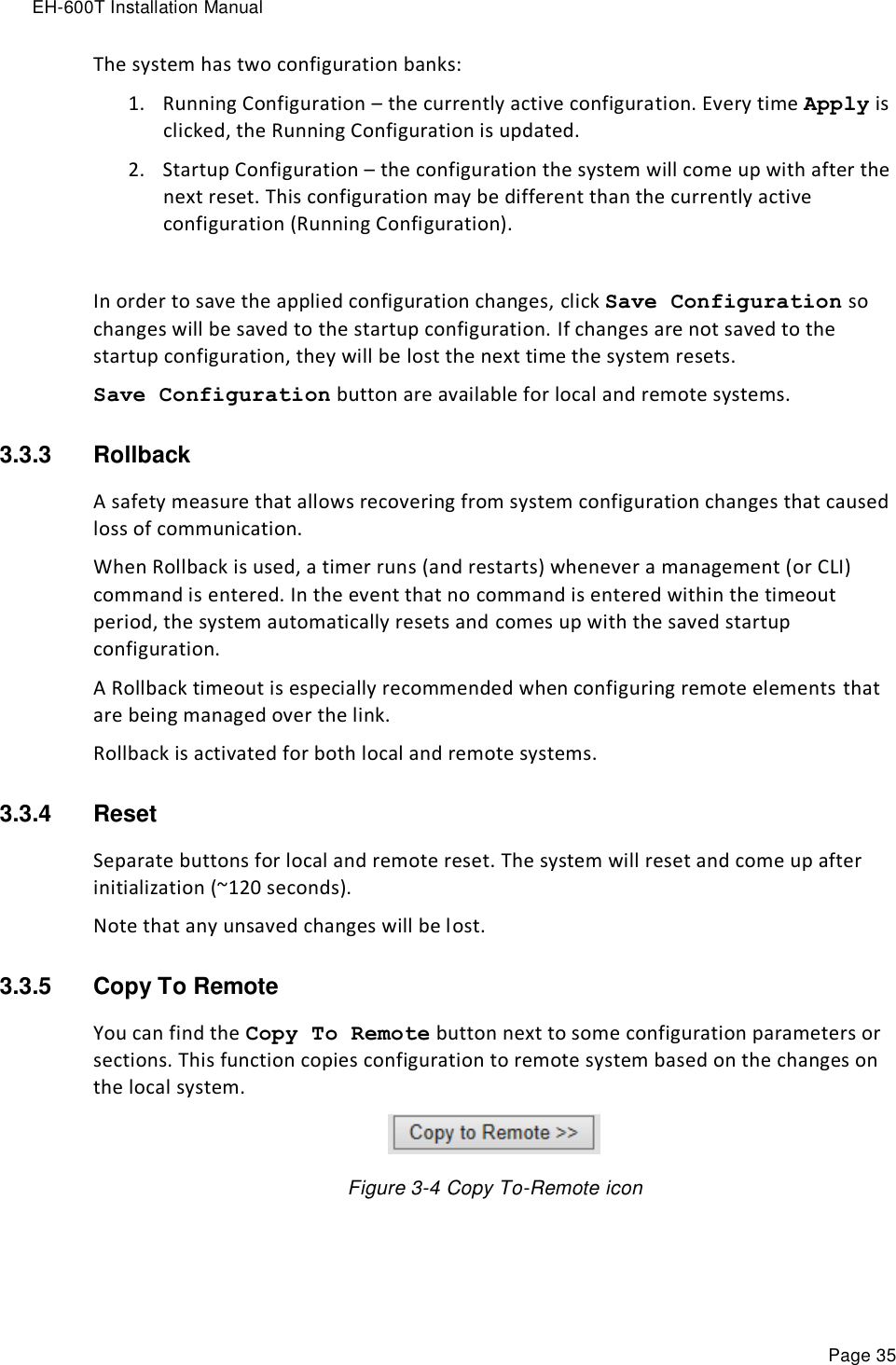
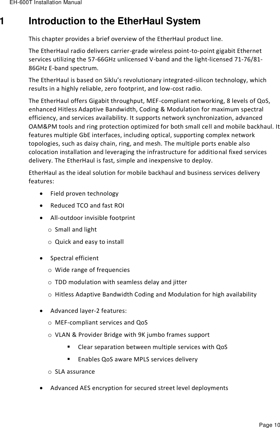
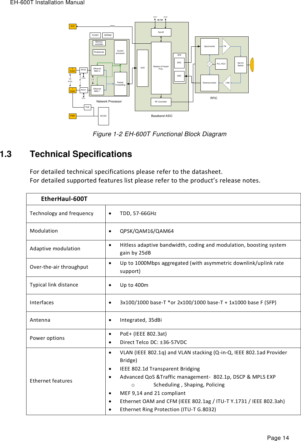
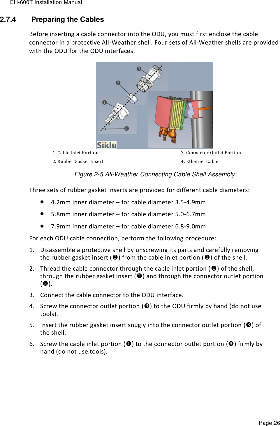
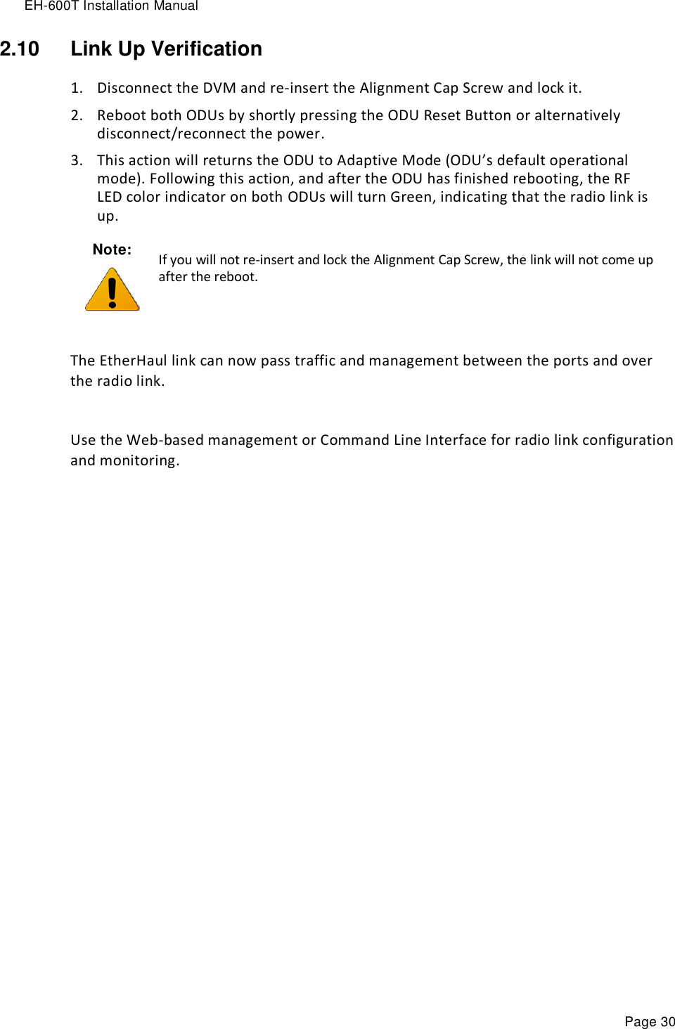
![EH-600T Installation Manual Page 36 Matching configuration may be of two types: Identical configuration – exactly same configuration will be copied from the local to remote system. It can be found for parameters that normally requires identical configuration for both local and remote units. For example, Encryption configuration. Matching configuration – for parameters that require matching but opposite configuration. For example, transmit frequency where Tx(local)=Rx(remote) and Rx(local)=Tx(remote). 3.4 Quick Configuration Wizard Use the Quick Configuration wizard to configure the basic system parameters. It holds the basic minimal configuration required to start using the link. The Quick Configuration wizard should be used for the initial system setup after installation. For monitoring and advanced configuration, please refer to the dedicated configuration pages of the Web-Based Management. To access the Quick Configuration wizard, go to the Quick Config page. 3.4.1 Quick Configuration: Step 1 – System Figure 3-5 Quick Config Page: Step 1 - System The first section allows configuring the following parameters: Name – you can give a name for each system Date – [YYYY.MM.DD] Time – [HH:MM:SS] Click Next to continue.](https://usermanual.wiki/Siklu-Communication/SK-60GTDD-A1/User-Guide-2382352-Page-36.png)
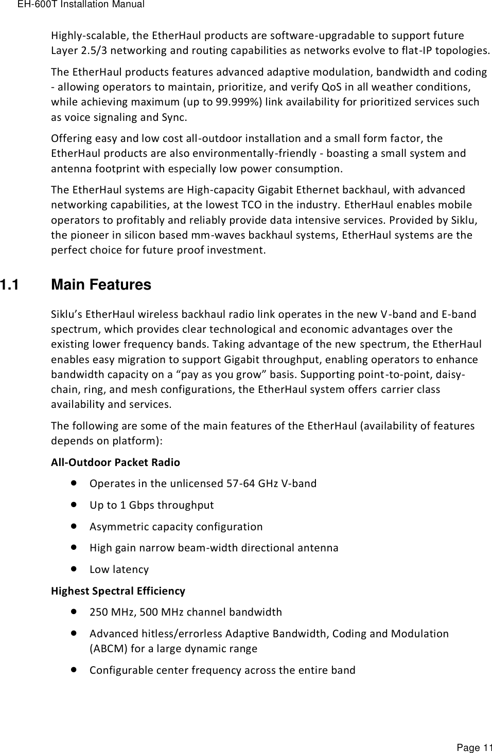
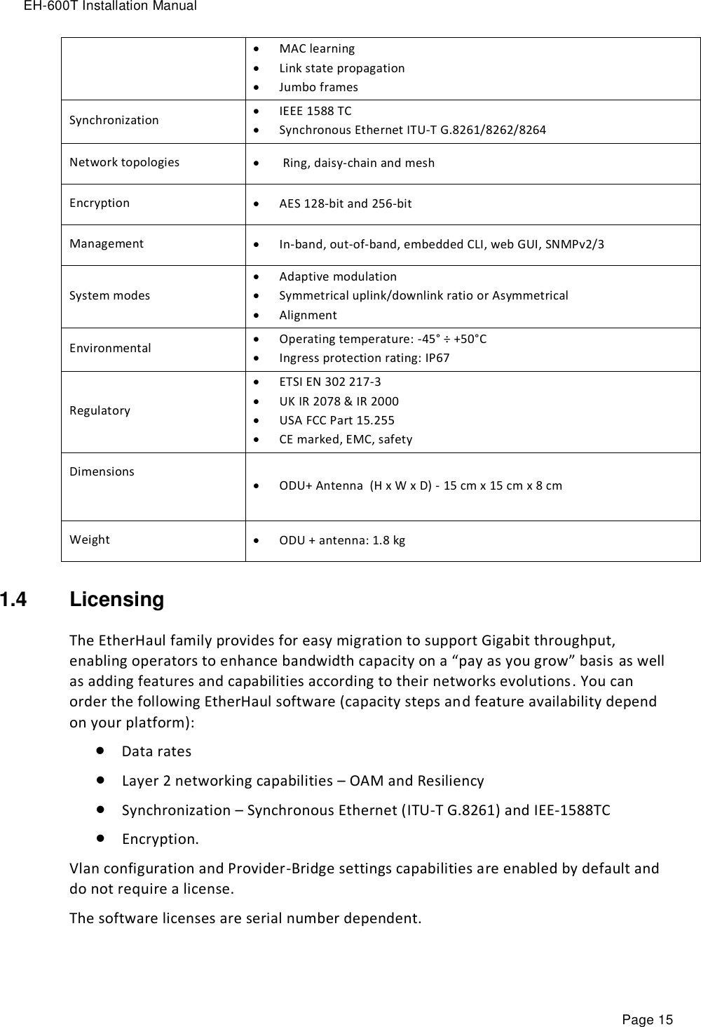
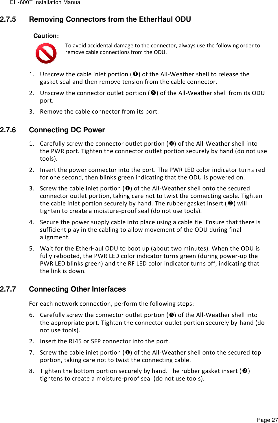
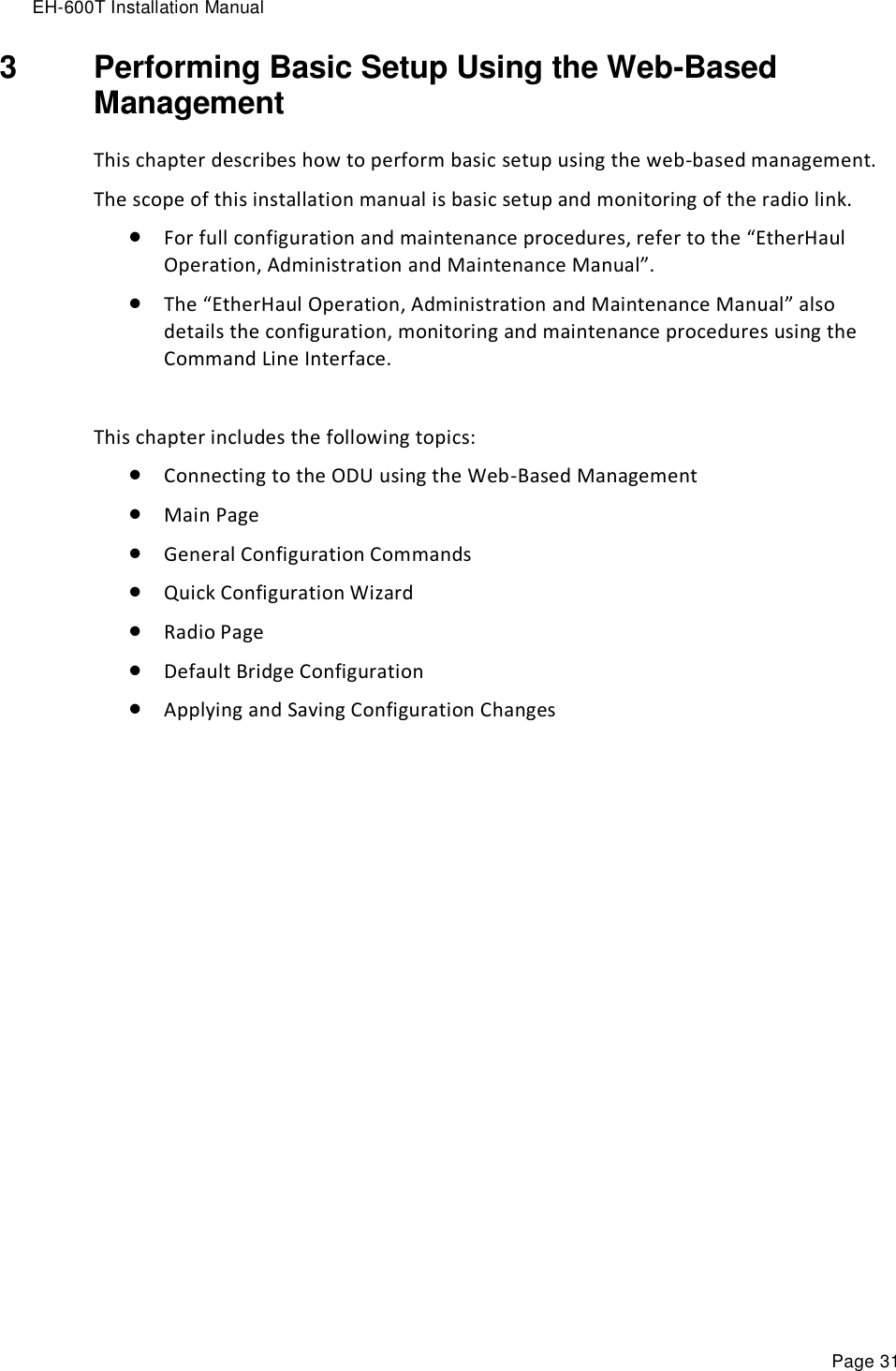
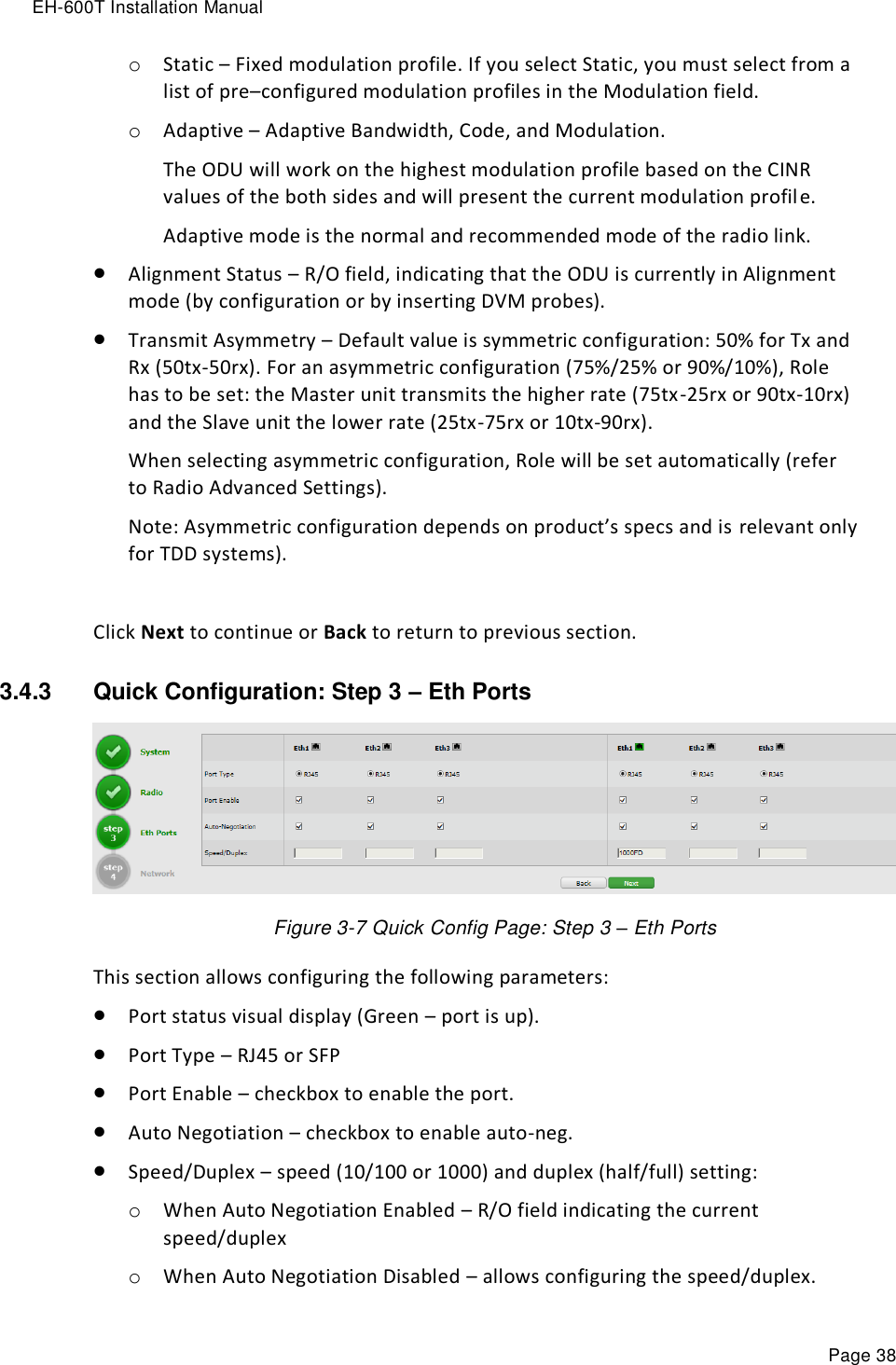
![EH-600T Installation Manual Page 37 3.4.2 Quick Configuration: Step 2 – Radio Figure 3-6 Quick Config Page: Step 2 - Radio This section allows configuring the following parameters: Channel Bandwidth [MHz] – 250 or 500MHz (default is 500MHz). Note: 250MHz support depends on product’s specs. Tx Frequency [MHz] – transmit frequency. Rx Frequency [MHz] – R/O field, updated based on Tx frequency. Tx Power [dBm] – ODU’s transmit power. Default is the max power, based on product’s specs. Minimum configurable Tx power is -35dBm (note that actual minimum Tx power is based on product’s specs). The Tx power value sets the transmit power for the highest modulation profile. In case lower modulation profile(s) has higher max Tx power (based on product’s specs), the Tx power will be increased automatically without indication in RF configuration menu. Mode – operational mode of the link: o Alignment – Carrier Wave transmission. Used for antenna alignment. No data over the radio link. Note: Adjust Tx Power so the RSSI at the remote end will not exceed -35dBm (overload threshold). Note: When exiting Alignment mode, perform system reset to allow proper operation of the radio link.](https://usermanual.wiki/Siklu-Communication/SK-60GTDD-A1/User-Guide-2382352-Page-37.png)
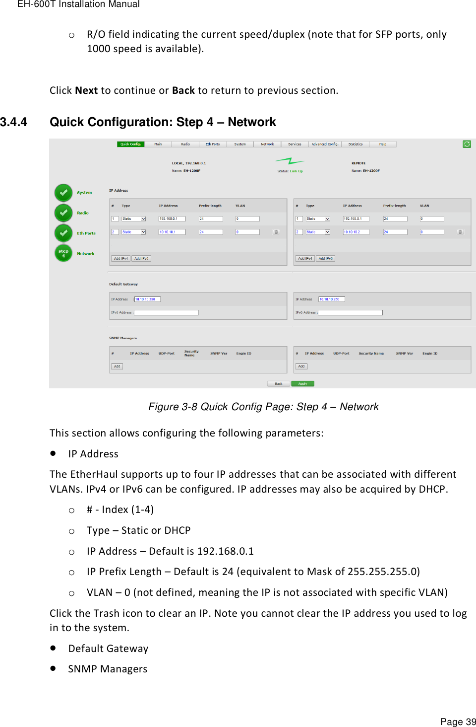
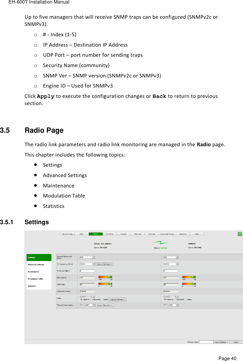
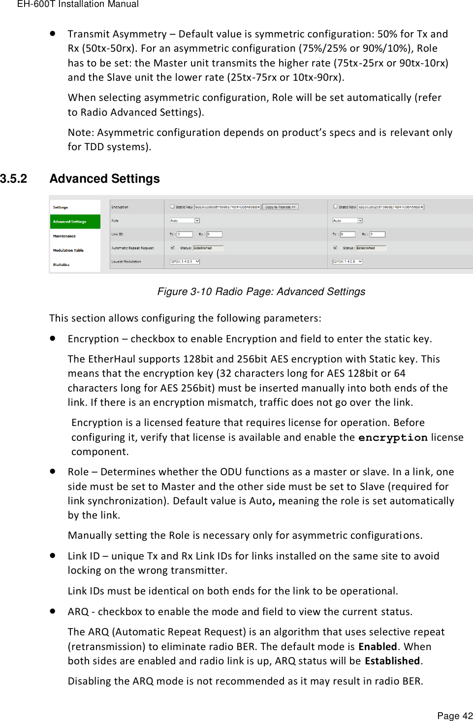
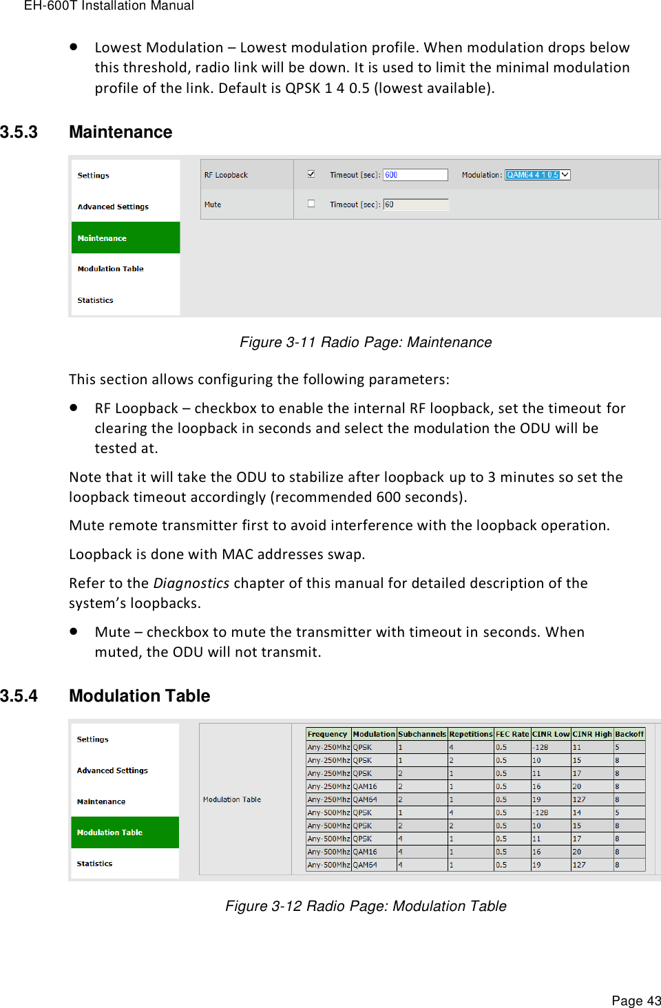
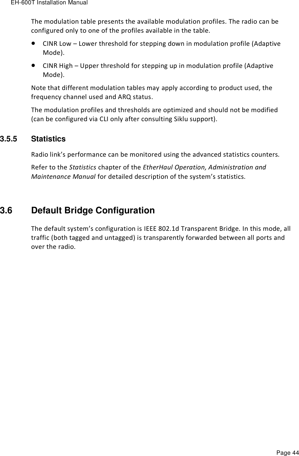
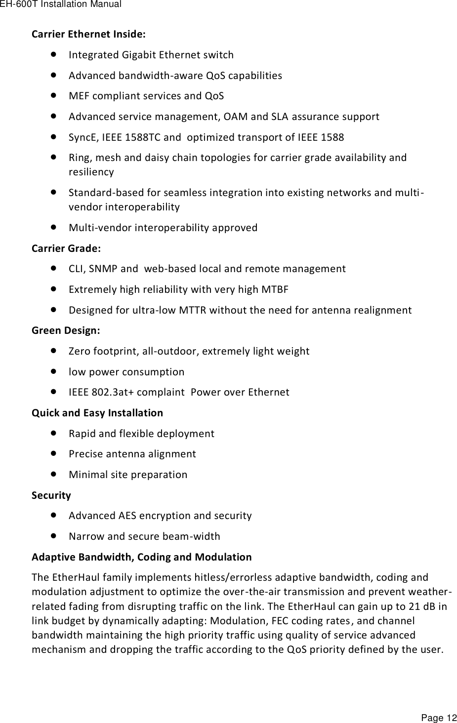
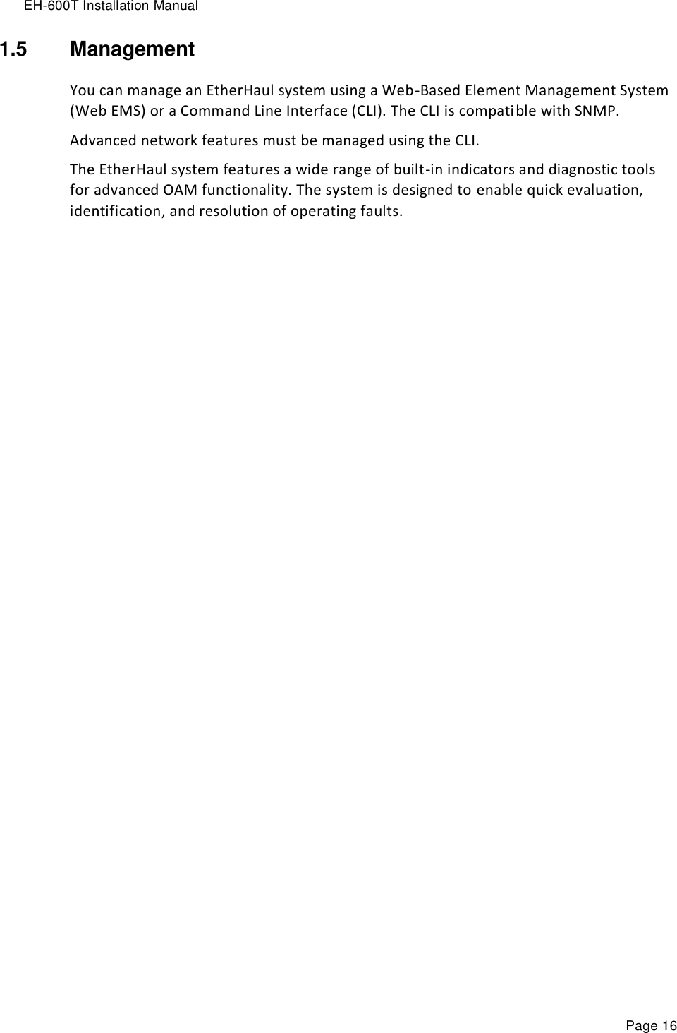
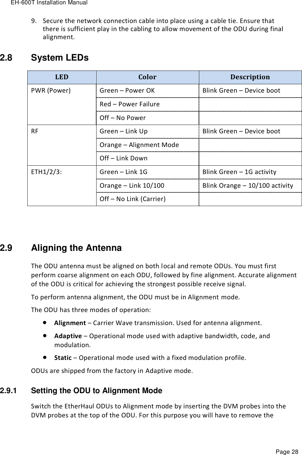
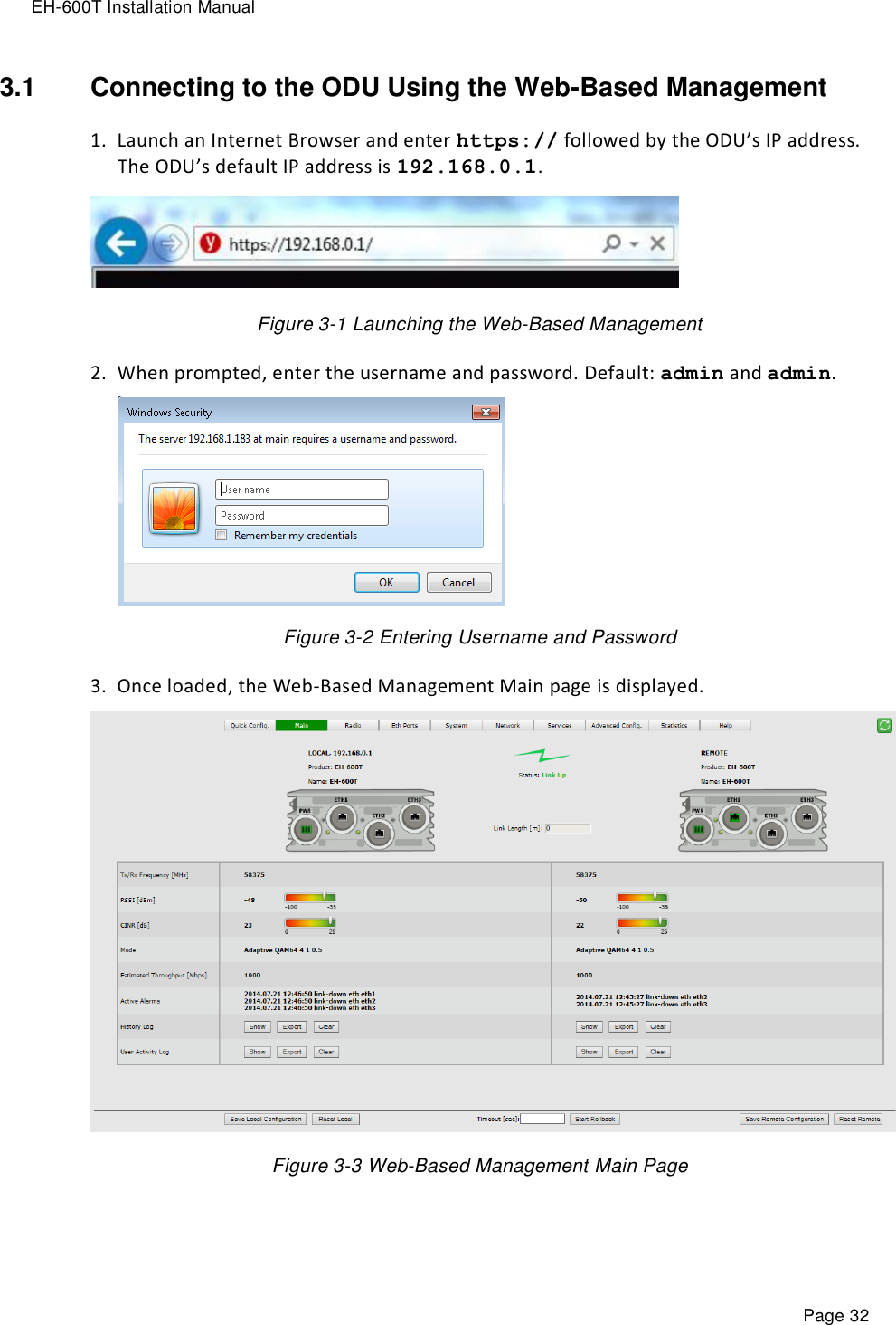
![EH-600T Installation Manual Page 41 Figure 3-9 Radio Page: Settings This section allows configuring the following parameters: Channel Bandwidth [MHz] – 250 or 500MHz (default is 500MHz). Note: 250MHz support depends on product’s specs and SW release. Tx Frequency [MHz] – transmit frequency. Rx Frequency [MHz] – R/O field, updated based on Tx frequency. o For TDD systems – identical Tx and Rx frequencies. Tx Power [dBm] – ODU’s transmit power. Default is the max power, based on product’s specs. Minimum configurable Tx power is -35dBm (note that actual minimum Tx power is based on product’s specs). The Tx power value sets the transmit power for the highest modulation profile. In case lower modulation profile(s) has higher max Tx power (based on product’s specs), the Tx power will be increased automatically without indication in RF configuration menu. Mode – operational mode of the link: o Alignment – Carrier Wave transmission. Used for antenna alignment. No data over the radio link. o Static – Fixed modulation profile. If you select Static, you must select from a list of pre–configured modulation profiles in the Modulation field. o Adaptive – Adaptive Bandwidth, Code, and Modulation. The ODU will work on the highest modulation profile based on the CINR values of the both sides and will present the current modulation profile. Adaptive mode is the normal and recommended mode of the radio link. Alignment Status – R/O field, indicating that the ODU is currently in Alignment mode (by configuration or by inserting DVM probes). Note: Adjust Tx Power so the RSSI at the remote end will not exceed -35dBm (overload threshold). Note: When exiting Alignment mode, perform system reset to allow proper operation of the radio link.](https://usermanual.wiki/Siklu-Communication/SK-60GTDD-A1/User-Guide-2382352-Page-41.png)