Siklu Communication SK-MH60CC-A1 Point-to-multipoint wireless V-band link User Manual
Siklu Communication Ltd. Point-to-multipoint wireless V-band link Users Manual
UserManual.wiki
>
Siklu Communication
>
SK MH60CC A1 User Manual
Users Manual
Navigation menu
Upload a User Manual
Namespaces
Wiki Guide
HTML
PDF
Info
Views
User Manual
Discussion / Help
Navigation

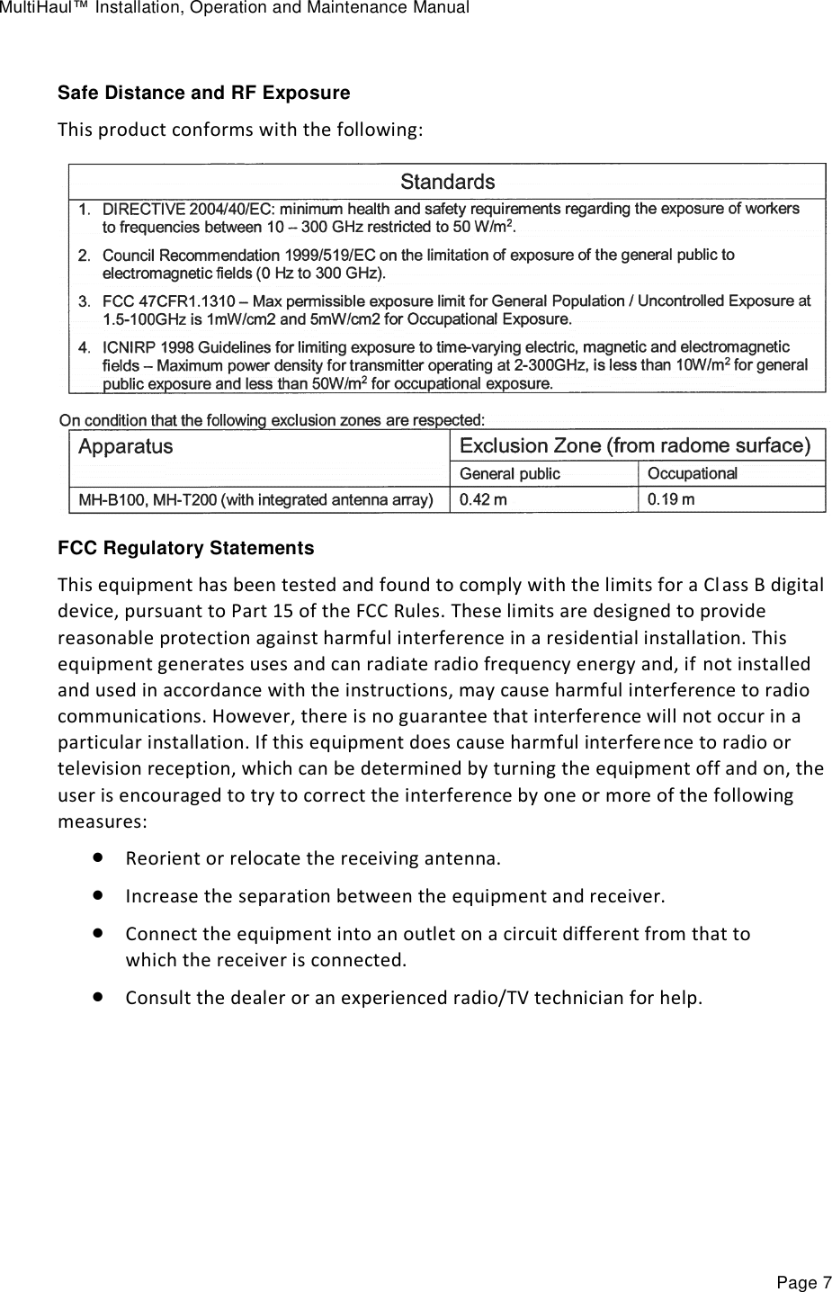

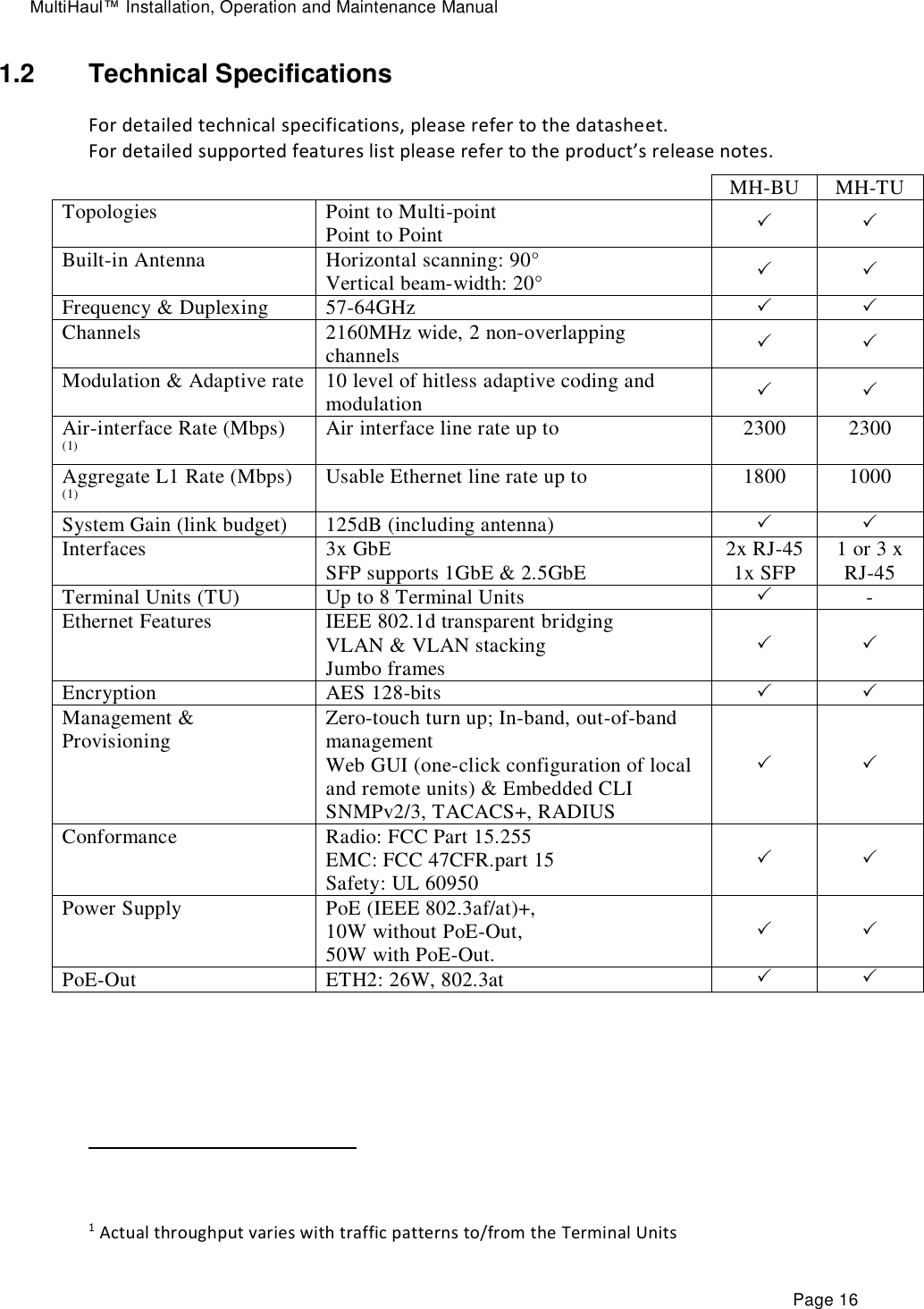
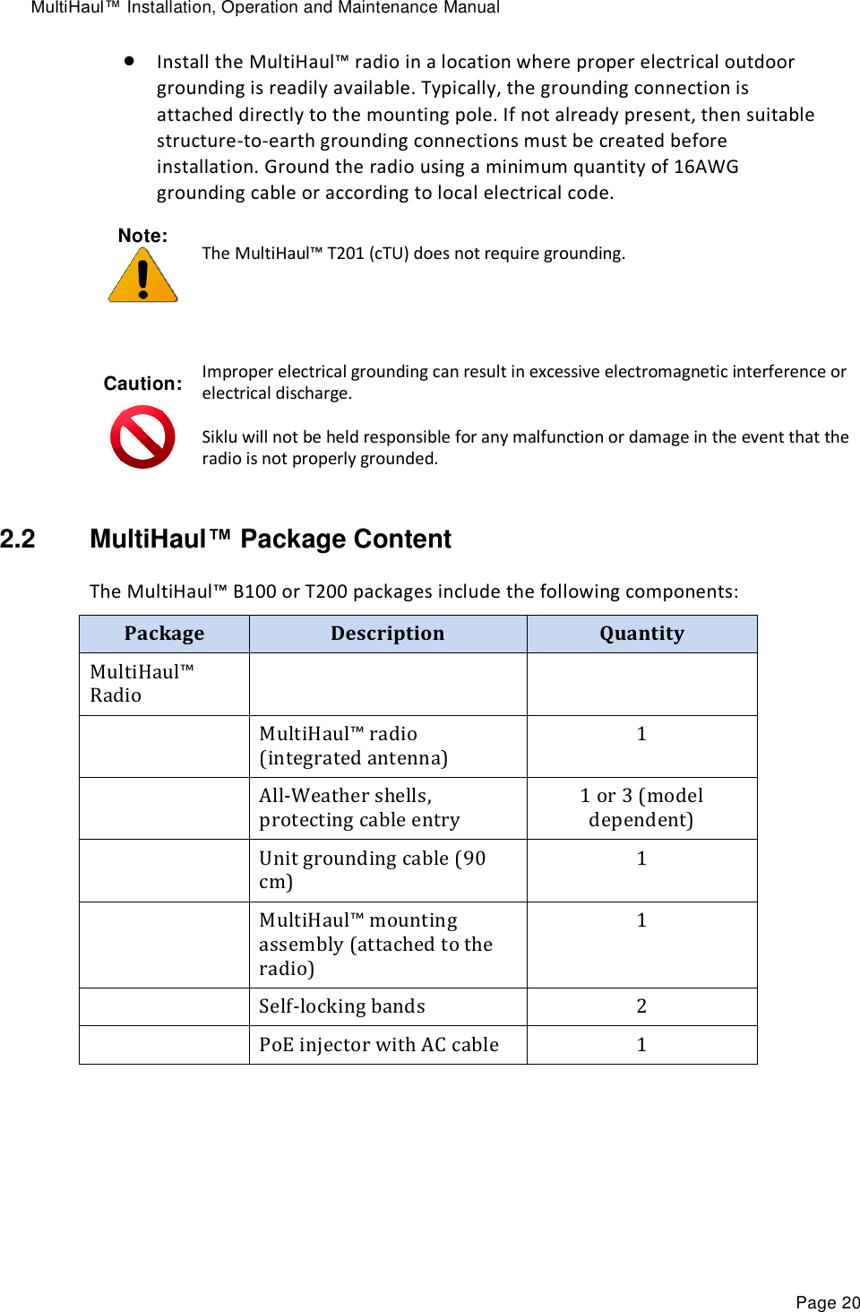
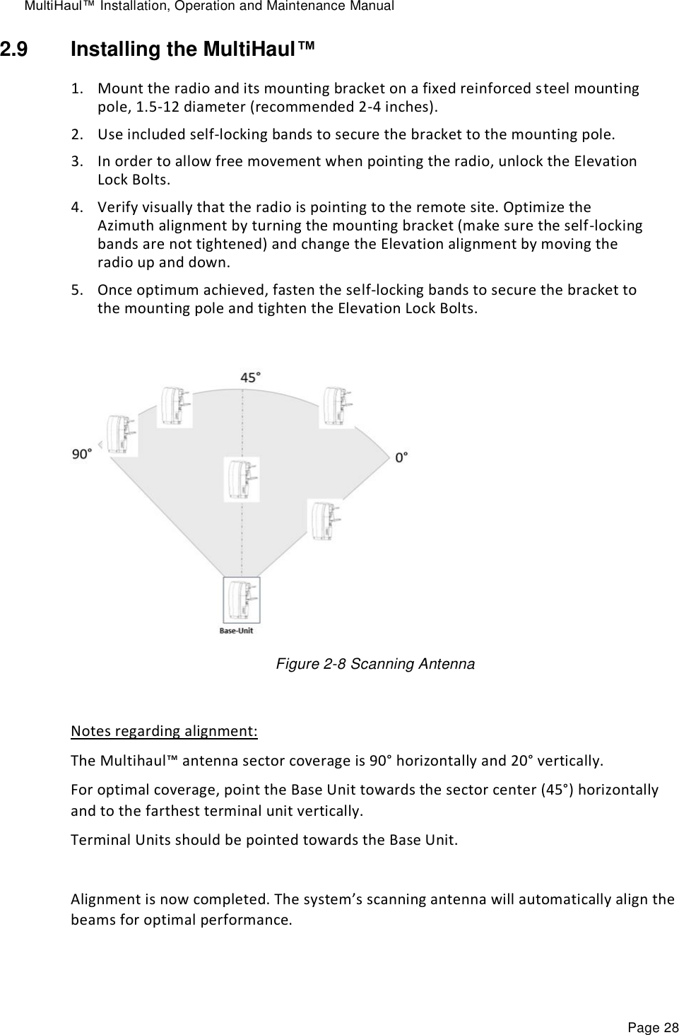
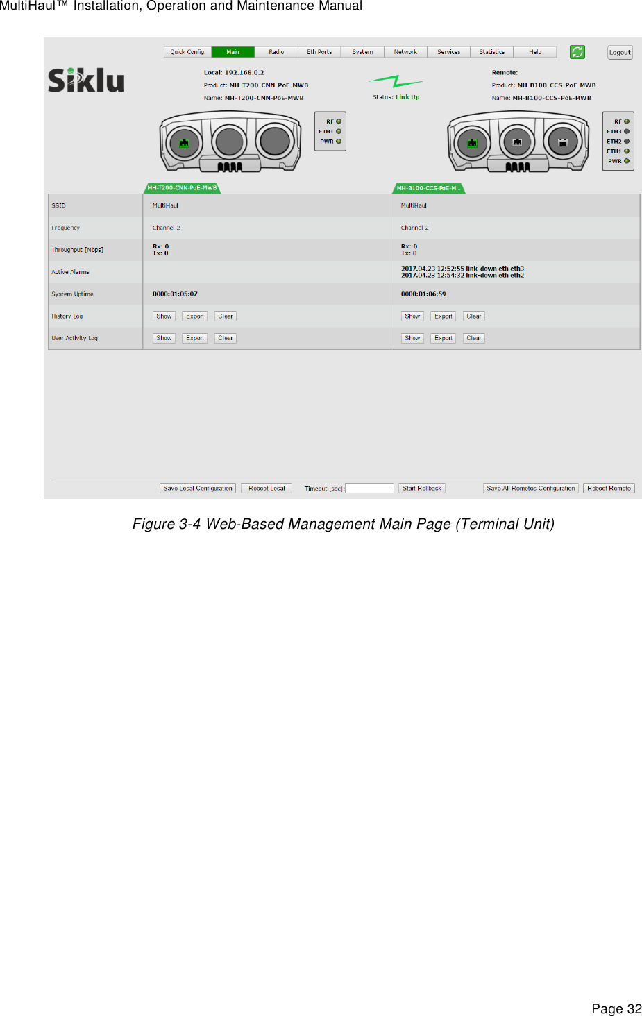
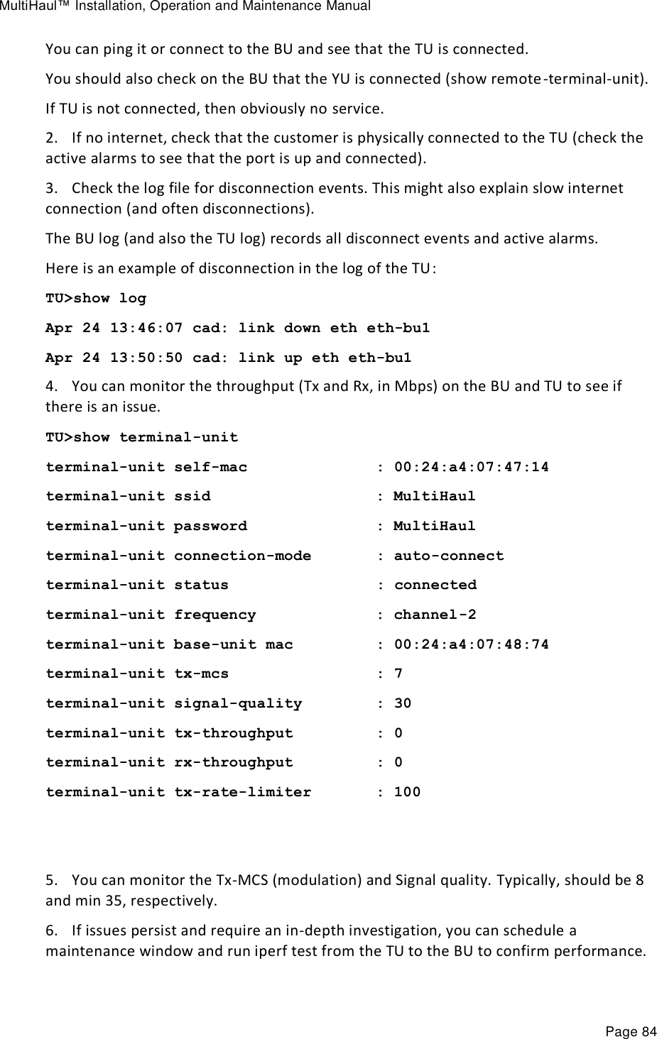
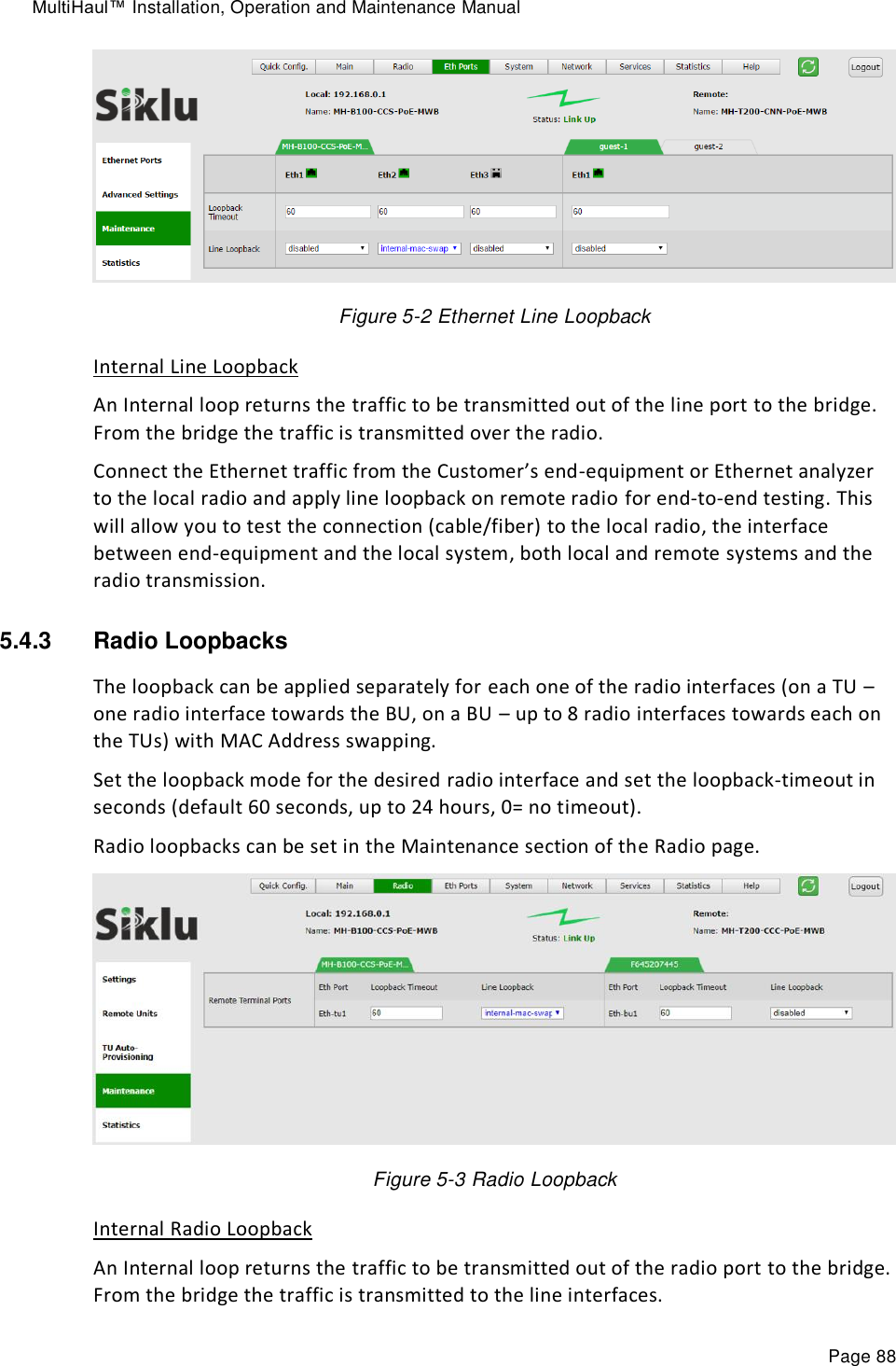
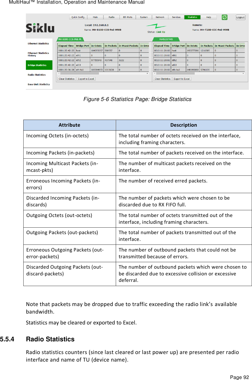
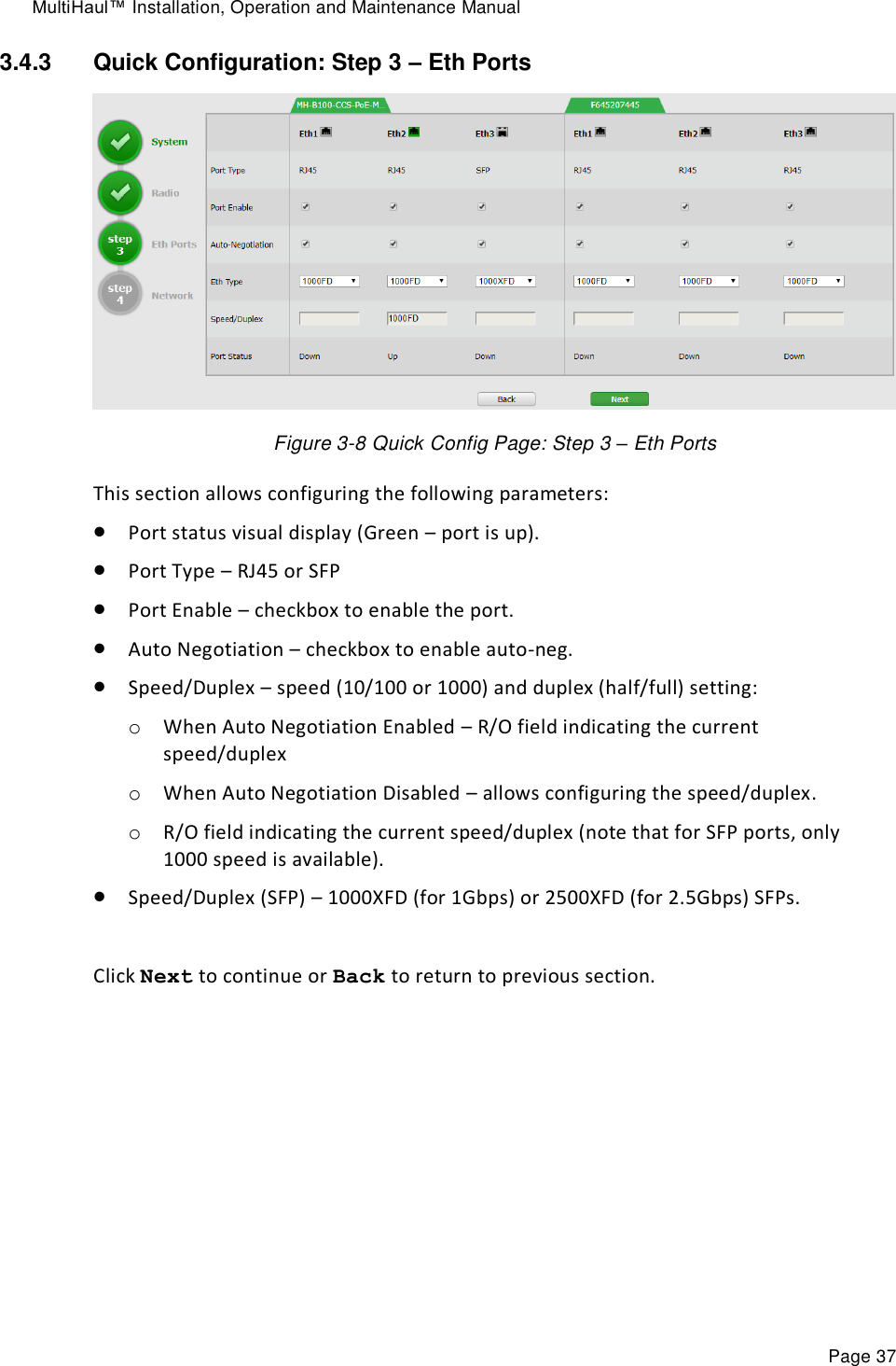
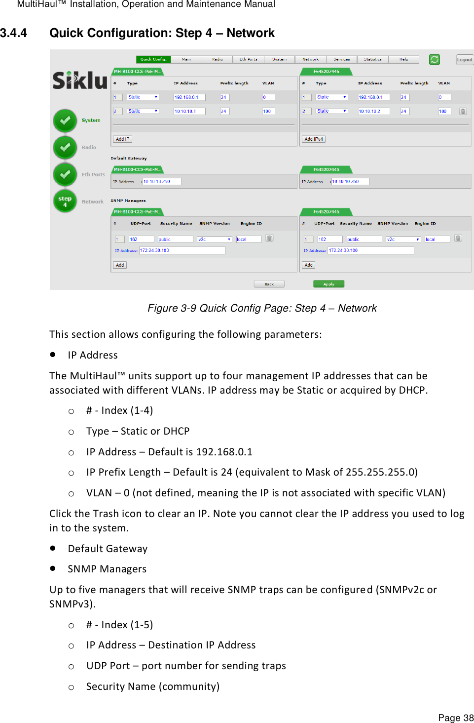
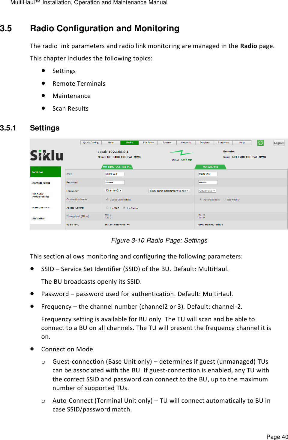
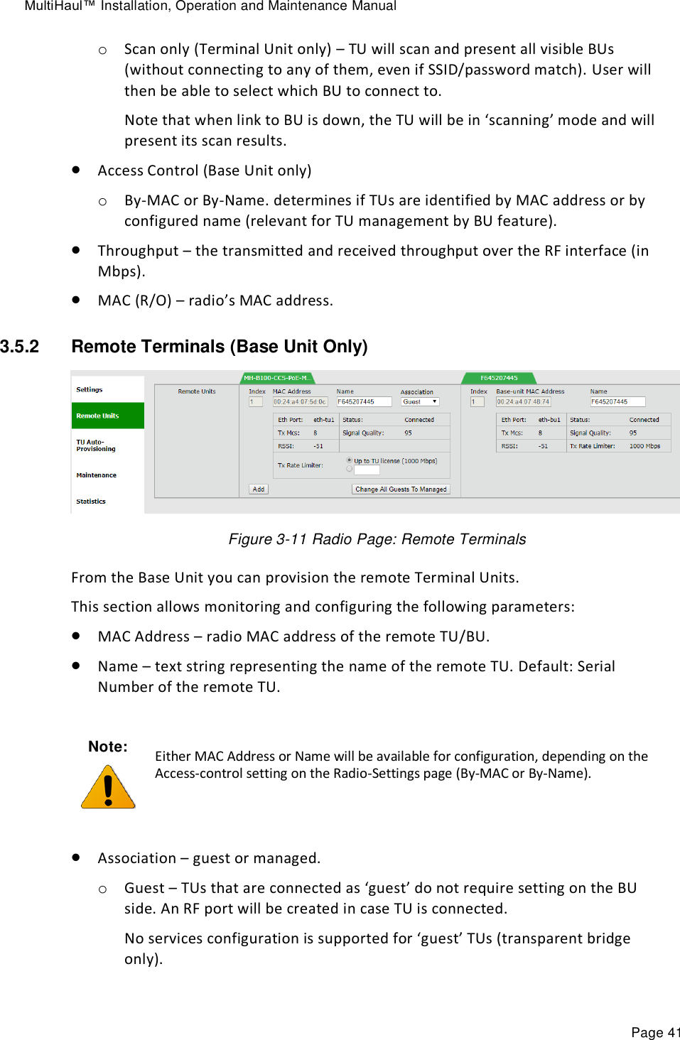
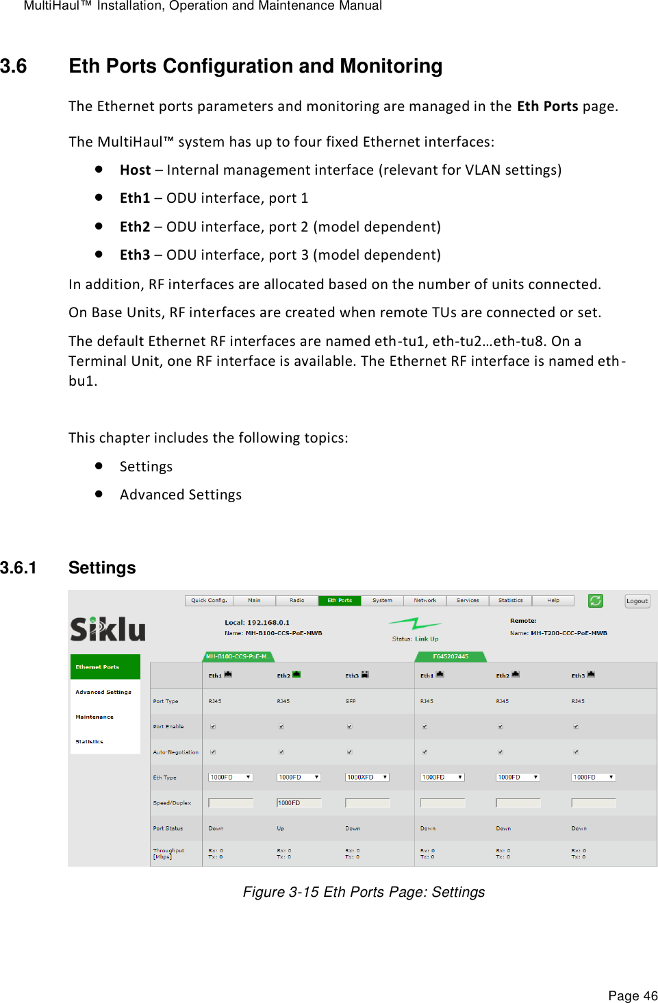
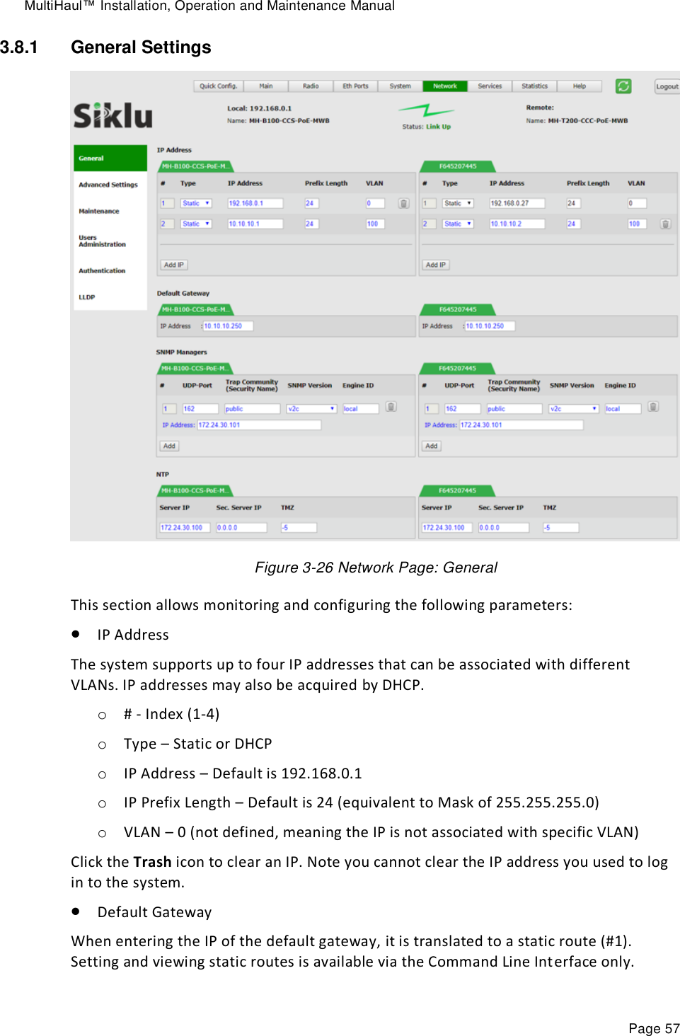
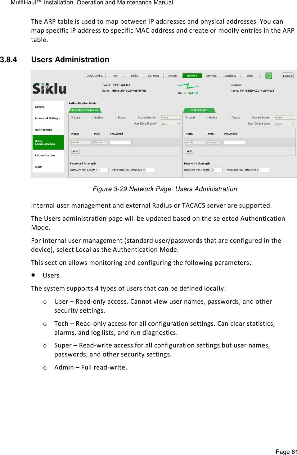
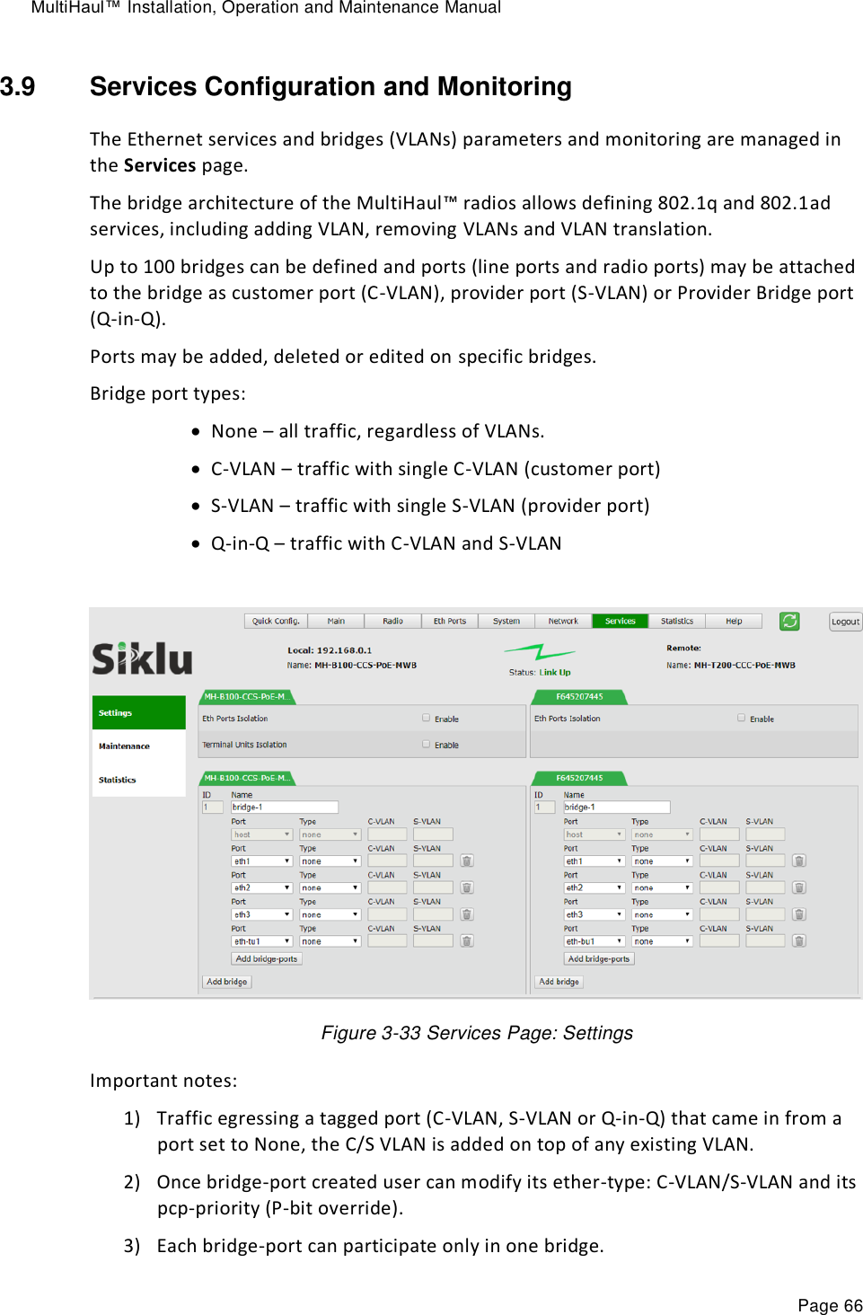
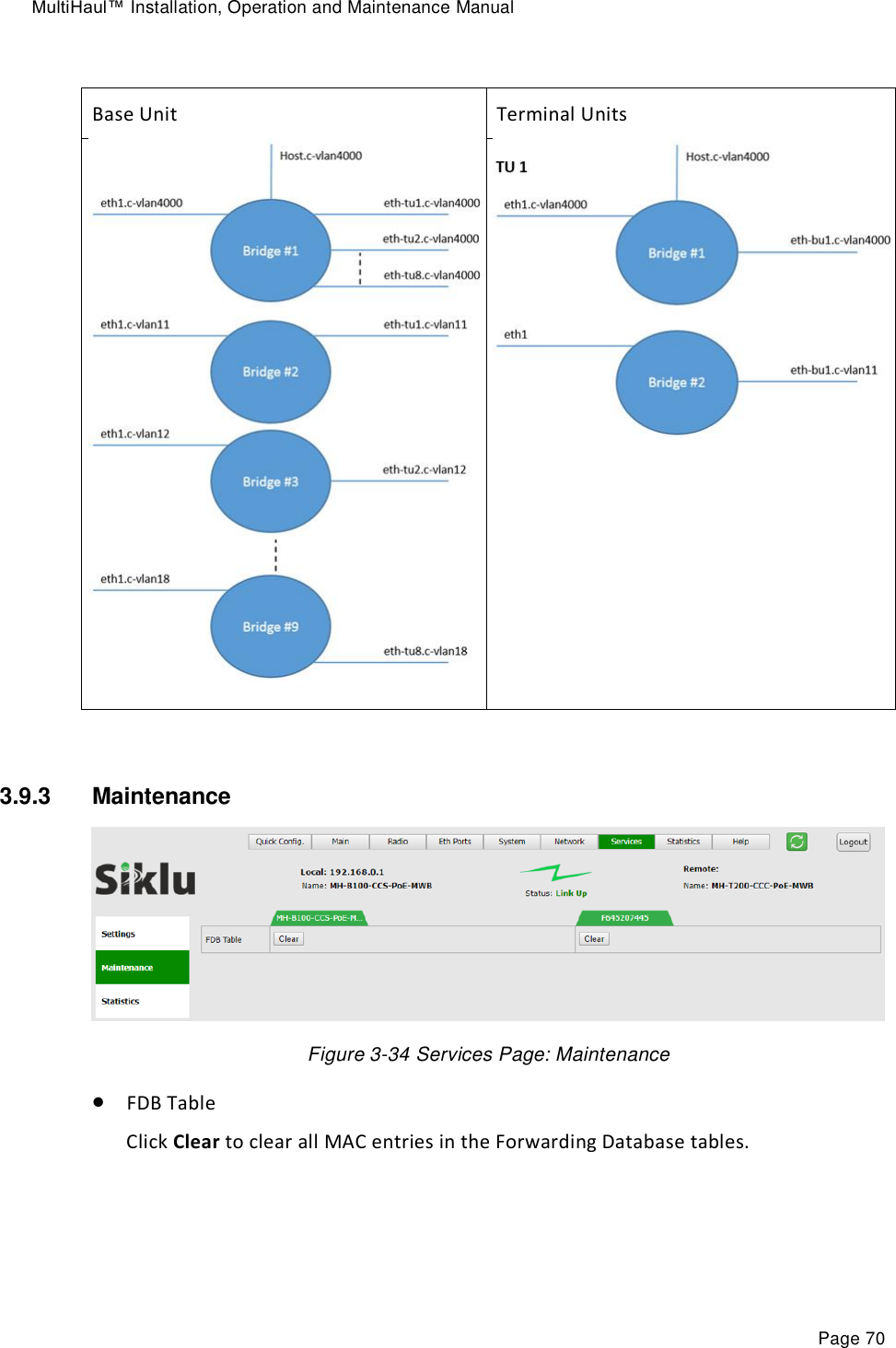
![MultiHaul™ Installation, Operation and Maintenance Manual Page 36 Figure 3-6 Quick Config Page: Step 1 - System The first section allows configuring the following parameters: Name – you can give a name to each system Date – [YYYY.MM.DD] Time – [HH:MM:SS] Click Copy to all to set identical Date & Time on remote terminals. Click Next to continue. 3.4.2 Quick Configuration: Step 2 – Radio Figure 3-7 Quick Config Page: Step 2 - Radio This section allows configuring the following parameters: SSID – Service Set Identifier (SSID) of the BU. Default: MultiHaul. The BU broadcasts openly its SSID. Password – password used for authentication. Default: MultiHaul. Frequency – the channel number (channel2 or 3). Default: channel-2. Frequency setting is available for BU only. The TU will scan and be able to connect to a BU on all channels. Connection Mode o Guest-connection (Base Unit only) – determines if guest (unmanaged) TUs can be associated with the BU. If guest-connection is enabled, any TU with the correct SSID and password can connect to the BU, up to the maximum number of supported TUs. o Auto-Connect (Terminal Unit only) – TU will connect automatically to BU in case SSID/password match. Access Control (Base Unit only) o By-MAC or By-Name. determines if TUs are identified by MAC address or by configured name (relevant for TU management by BU feature). MAC (R/O) – radio’s MAC address.](https://usermanual.wiki/Siklu-Communication/SK-MH60CC-A1/User-Guide-4104670-Page-36.png)

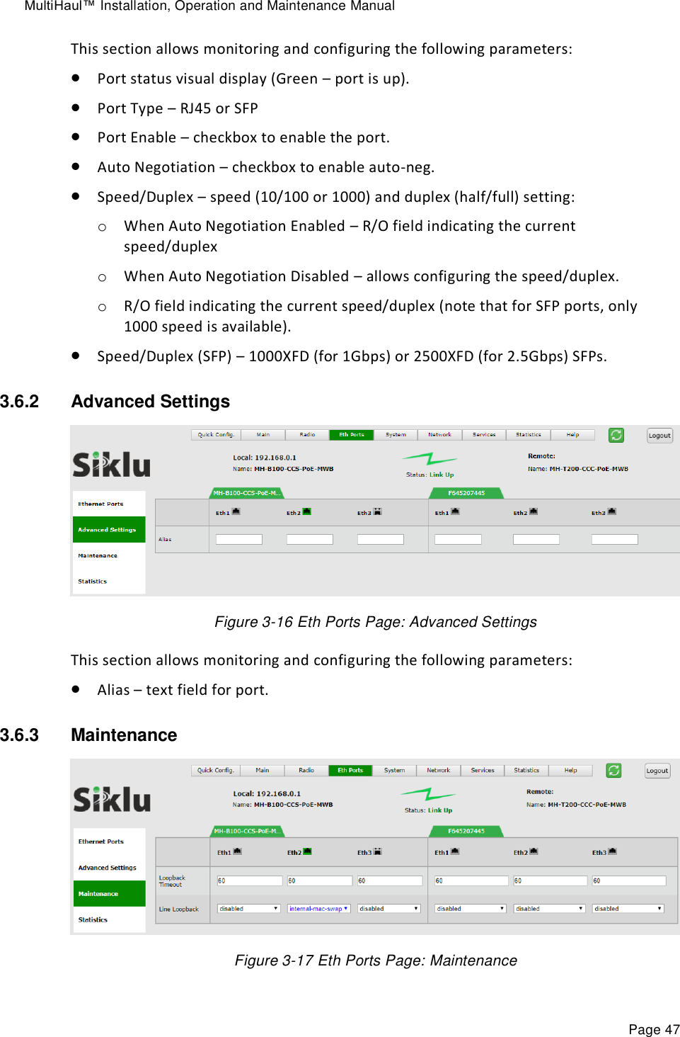

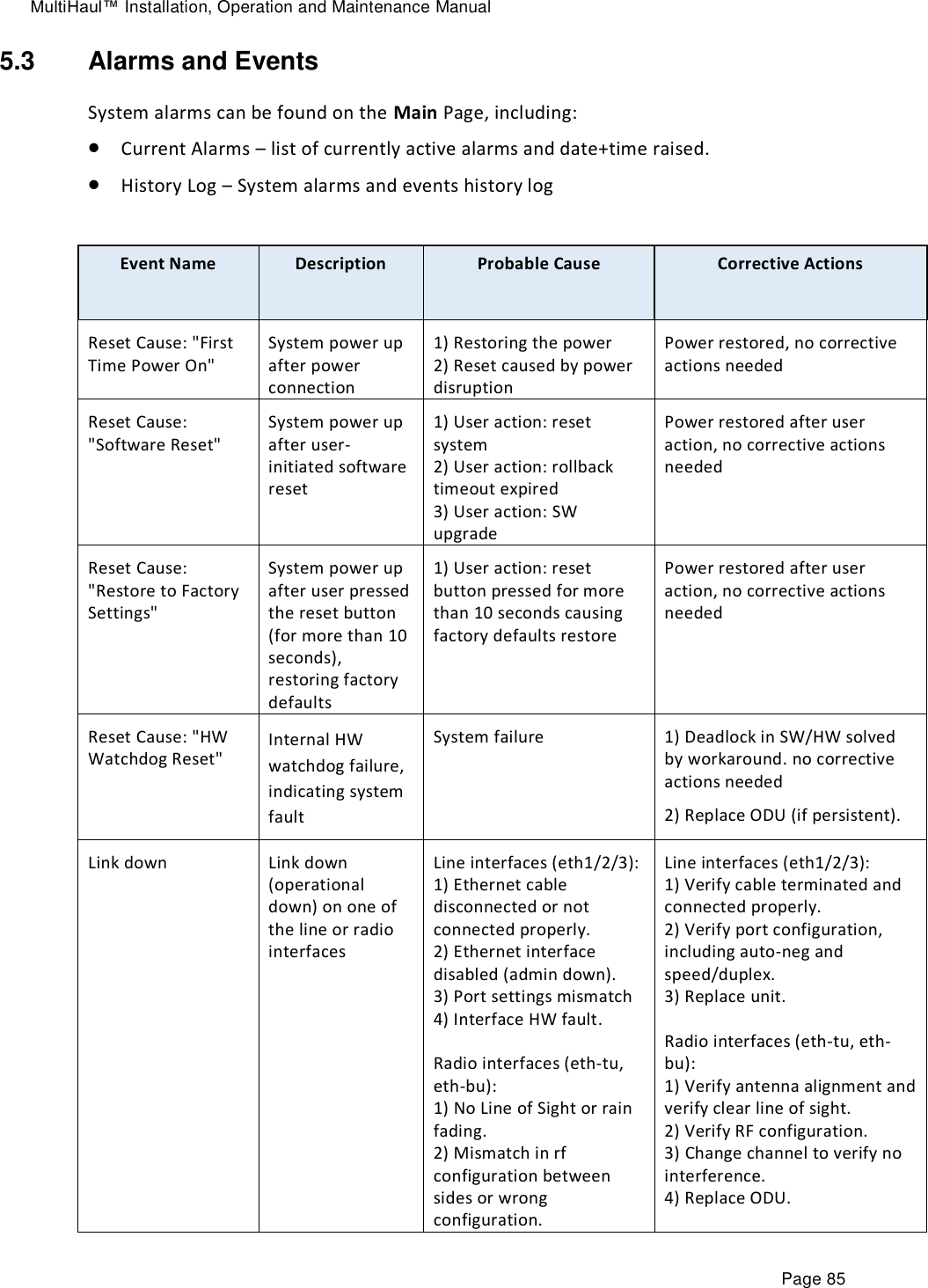
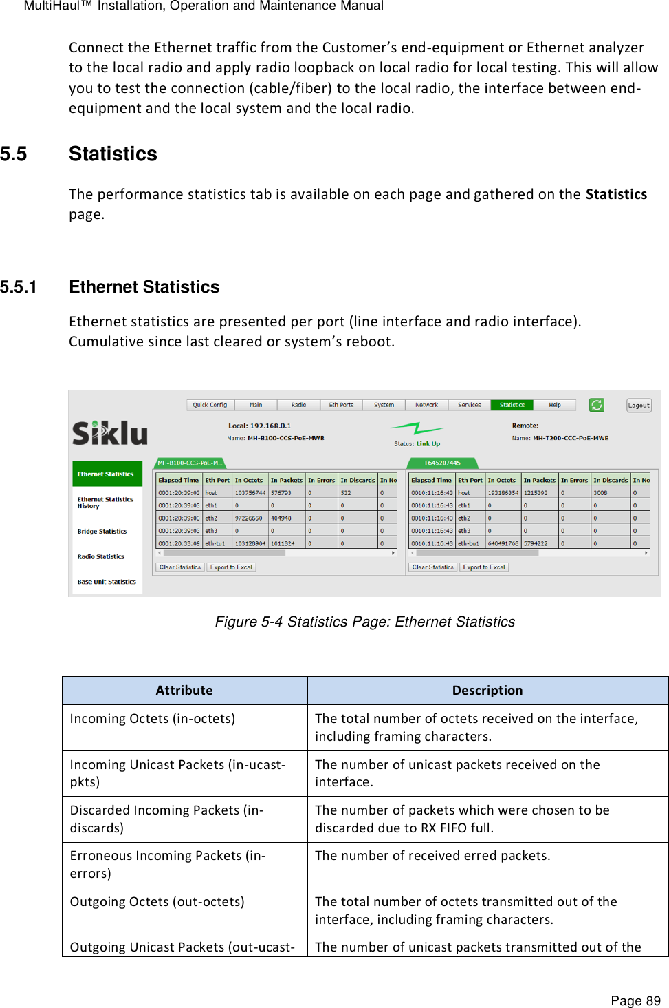
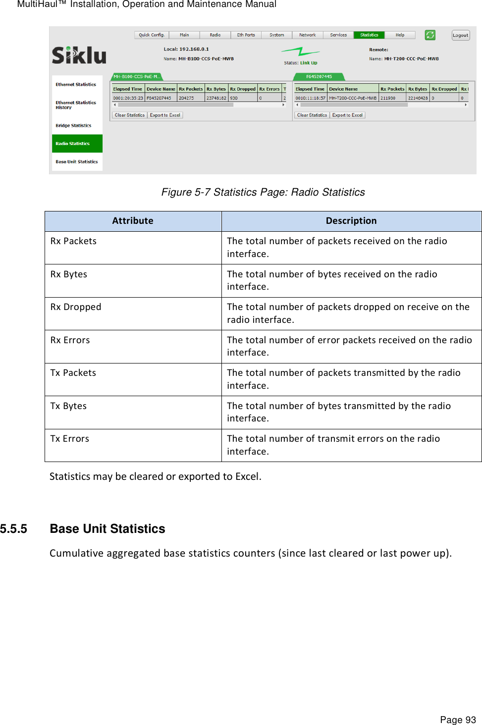
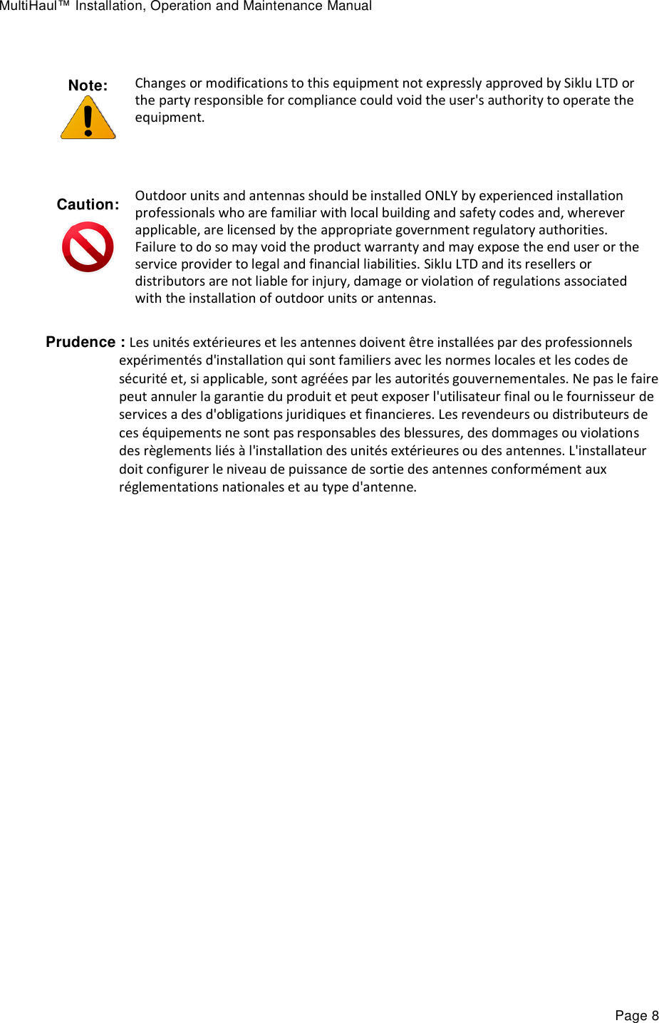
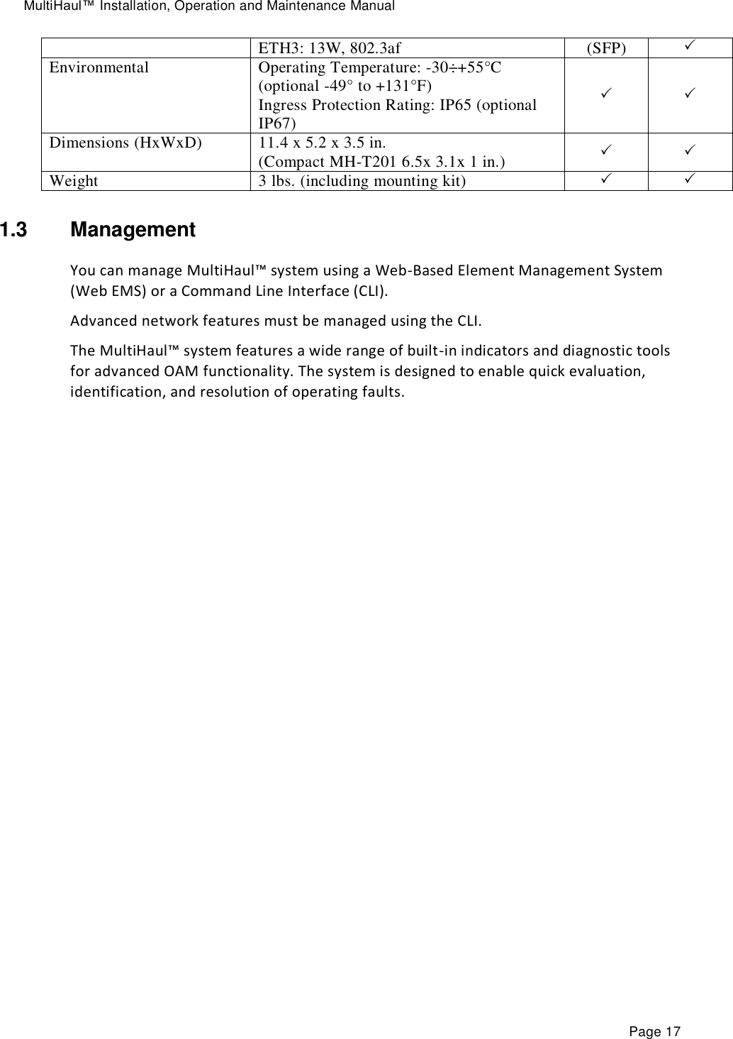
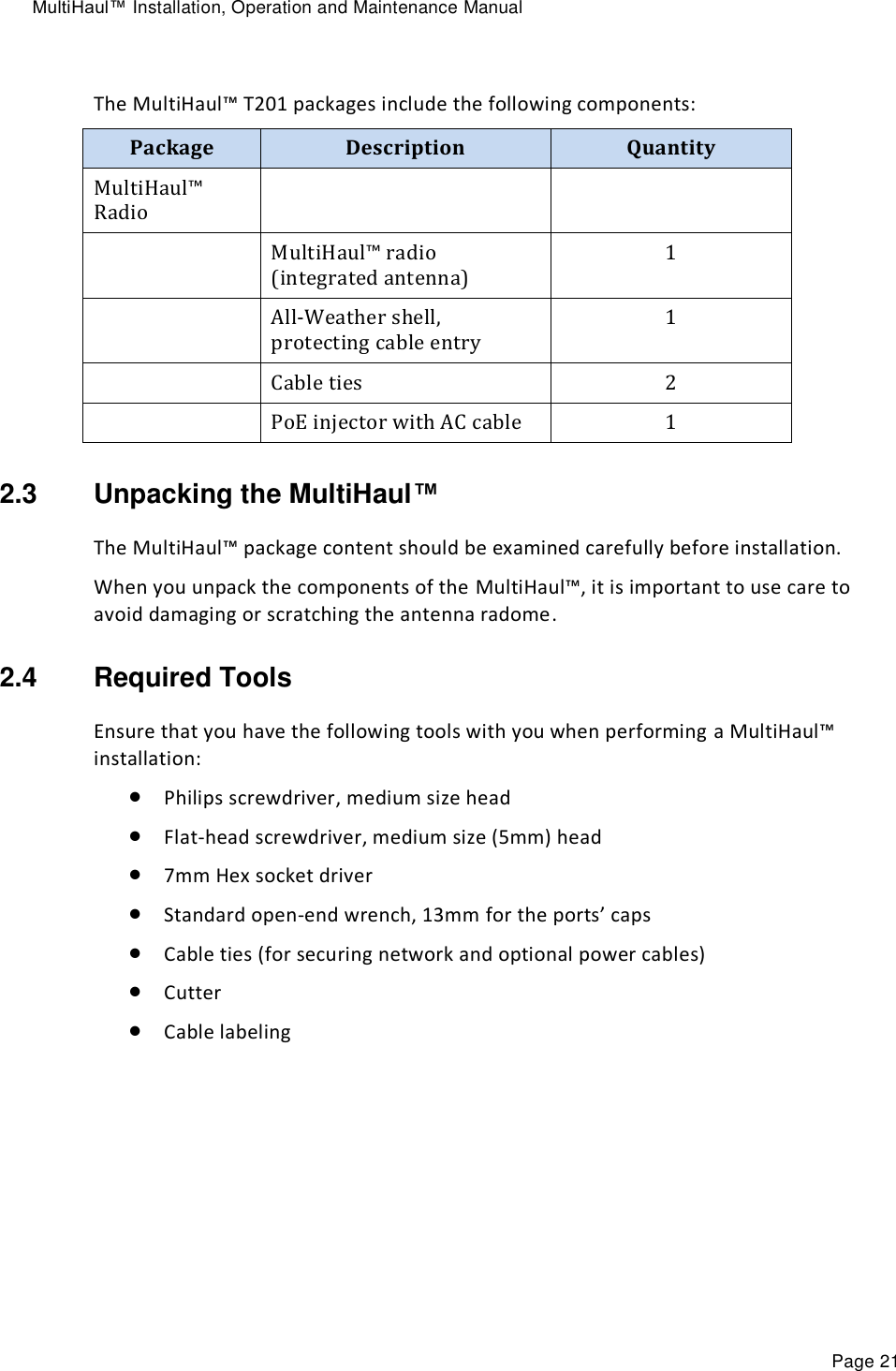
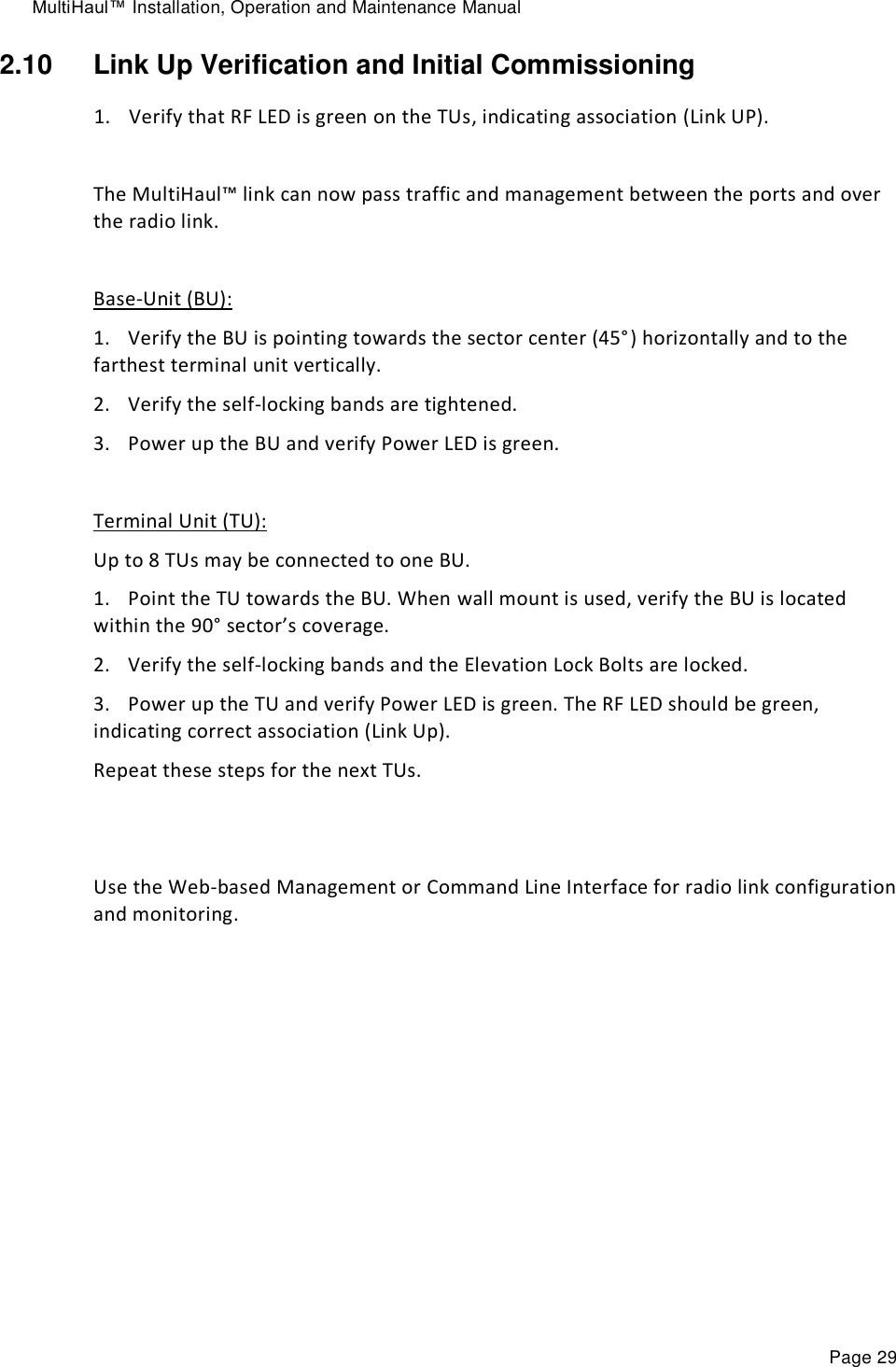
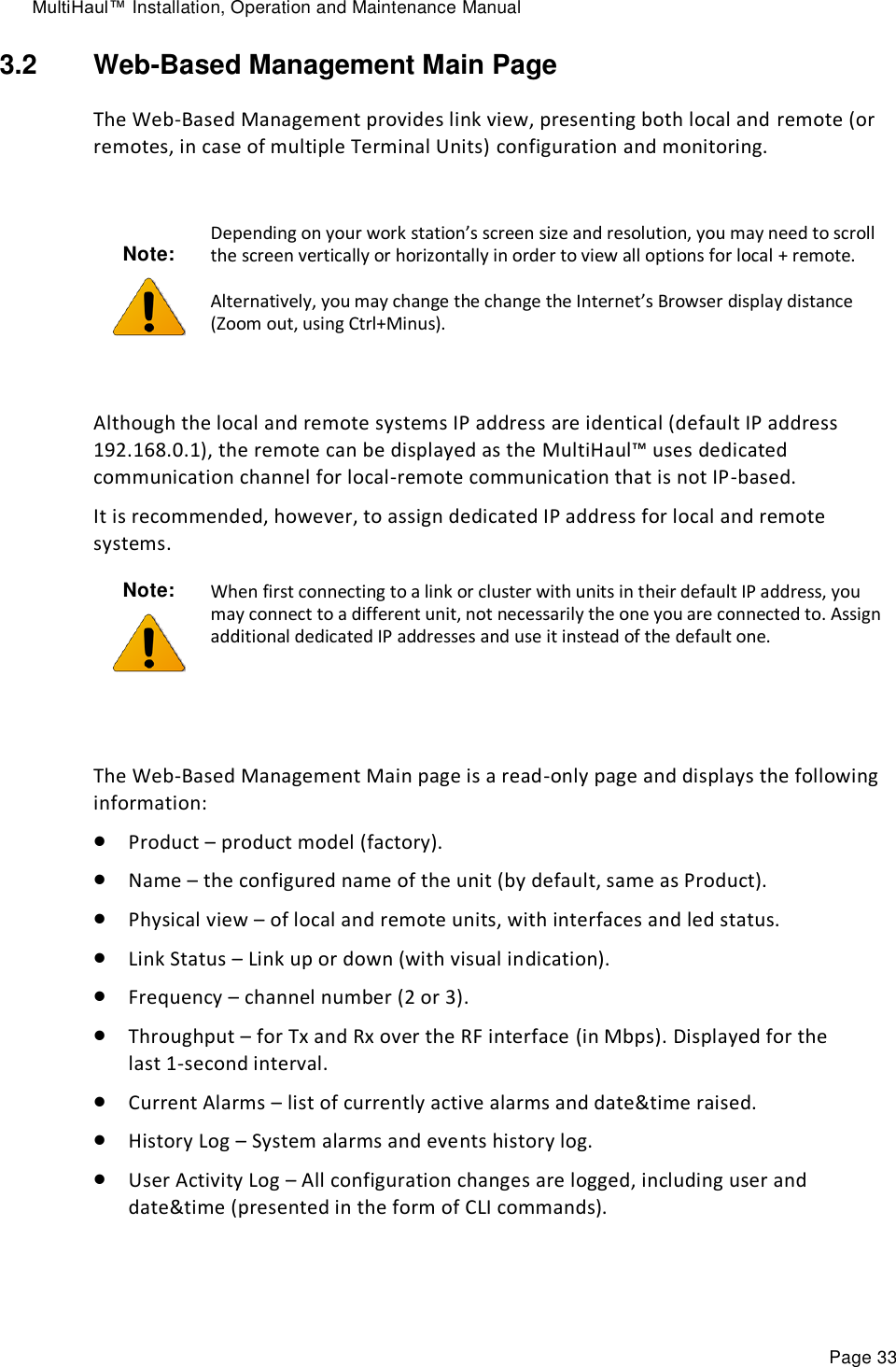
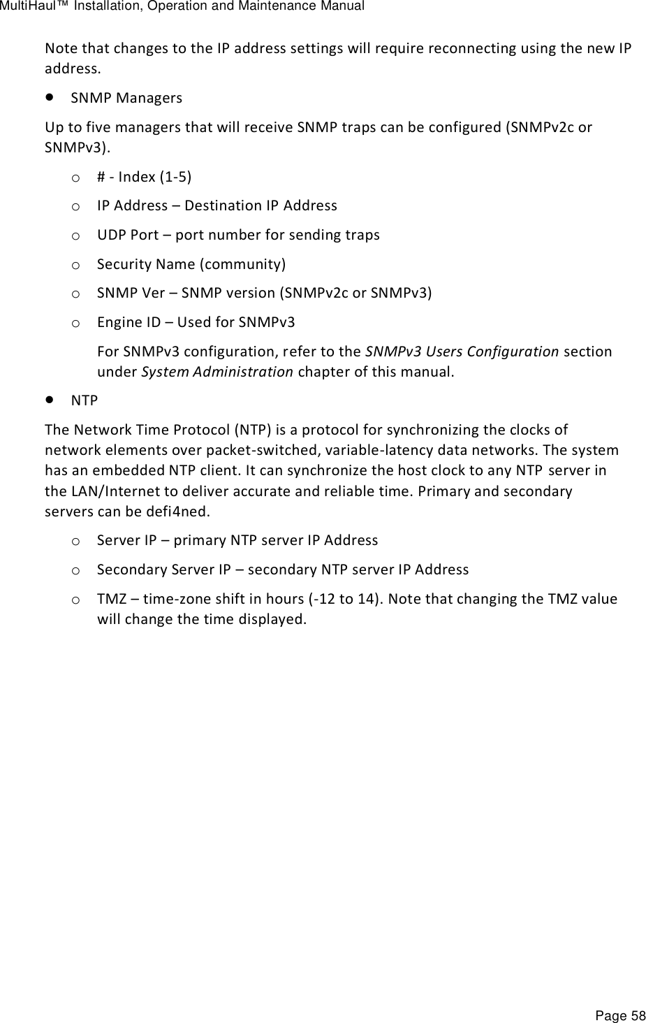
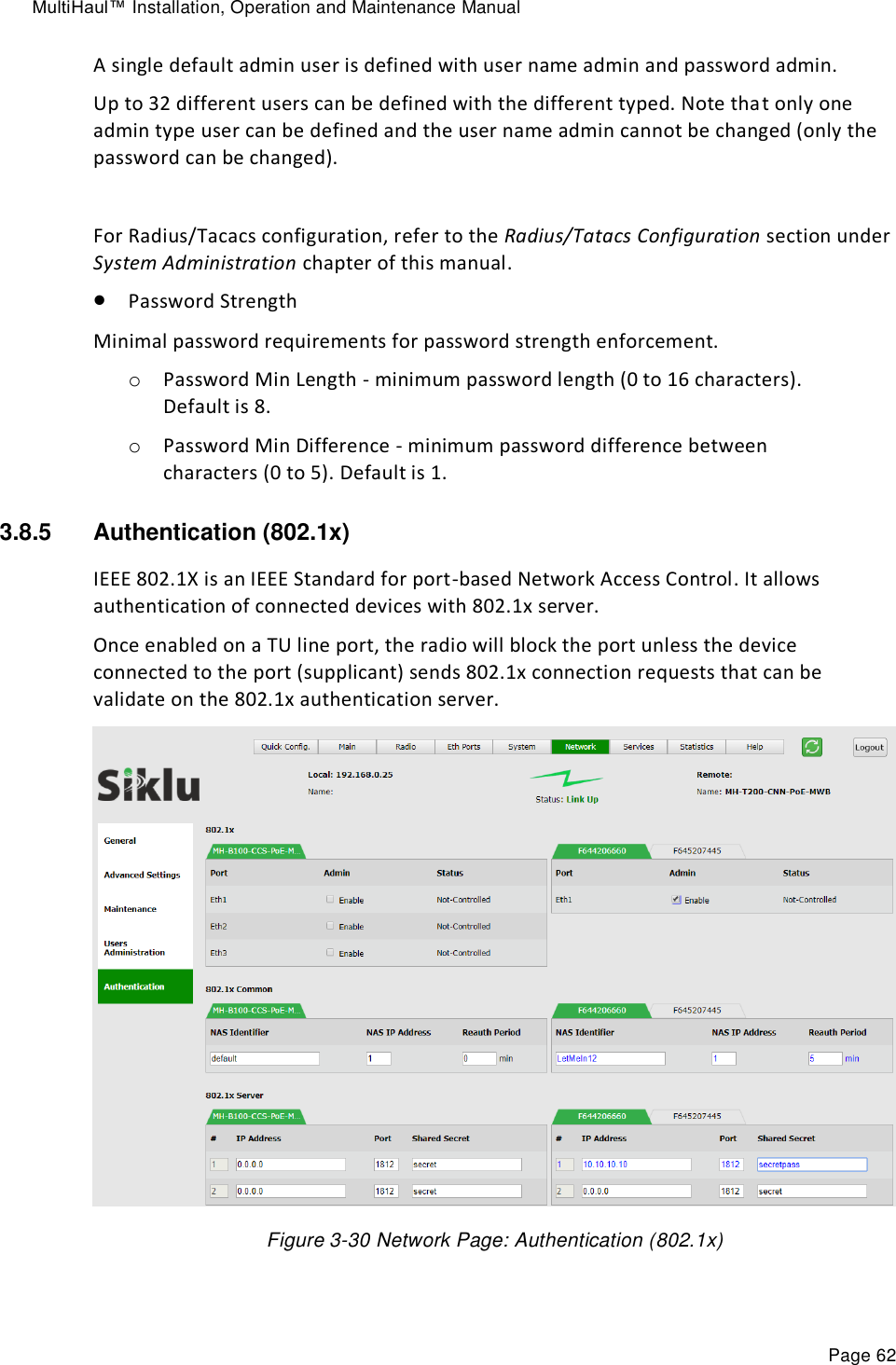
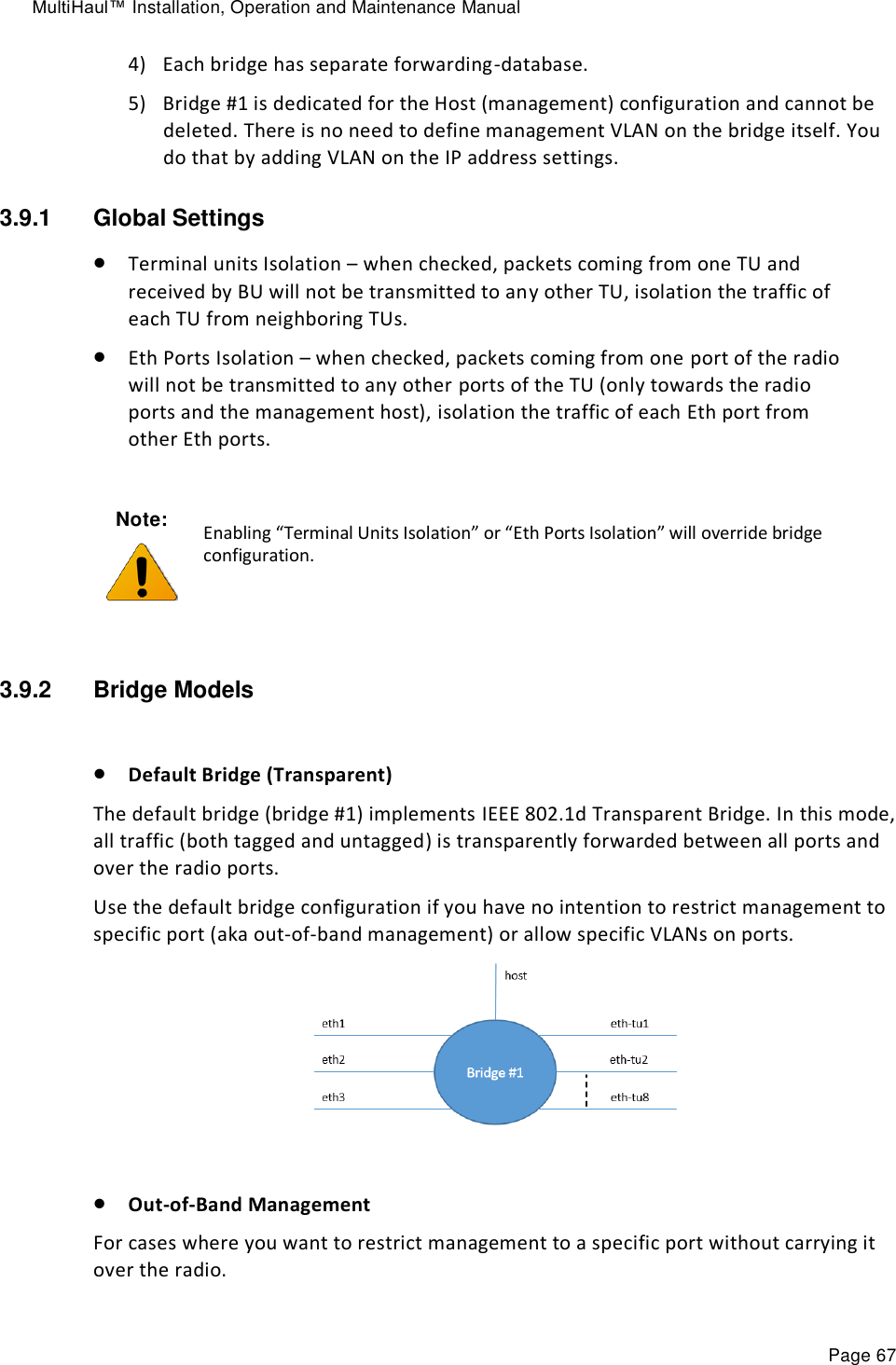
![MultiHaul™ Installation, Operation and Maintenance Manual Page 49 3.7 System Configuration and Monitoring The system general parameters and monitoring is managed in the System page. This chapter includes the following topics: General Settings Advanced Settings Maintenance Event Configuration The Maintenance section consists of the system's configuration files and file-system management, including: File Transfer SW Upgrade Licensing Scripts Configuration Management 3.7.1 General Settings Figure 3-18 System Page: General This section allows monitoring and configuring the following parameters: Model Name – (R/O) Product model. Name – Unique name for each system. Date & Time – Date [YYYY.MM.DD], Time [HH:MM:SS] Inventory – R/O fields. Serial Number and active SW version. MAC Address – R/O fields for each port.](https://usermanual.wiki/Siklu-Communication/SK-MH60CC-A1/User-Guide-4104670-Page-49.png)
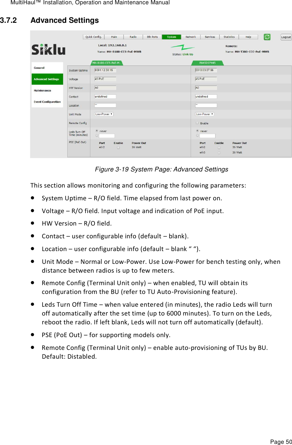
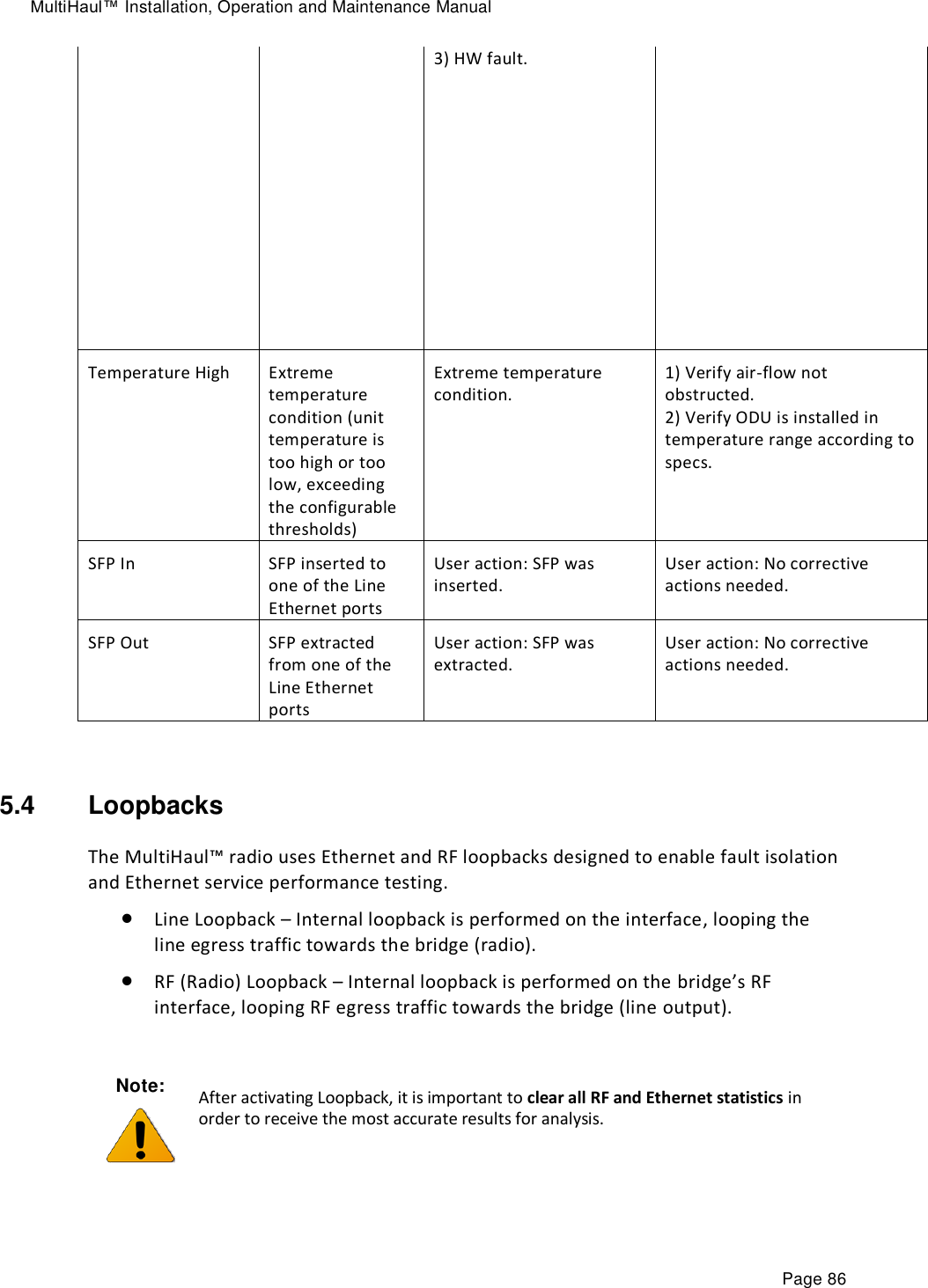
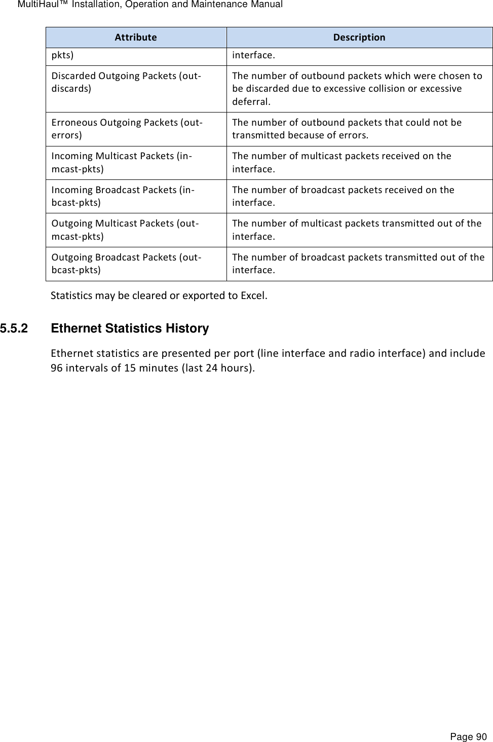
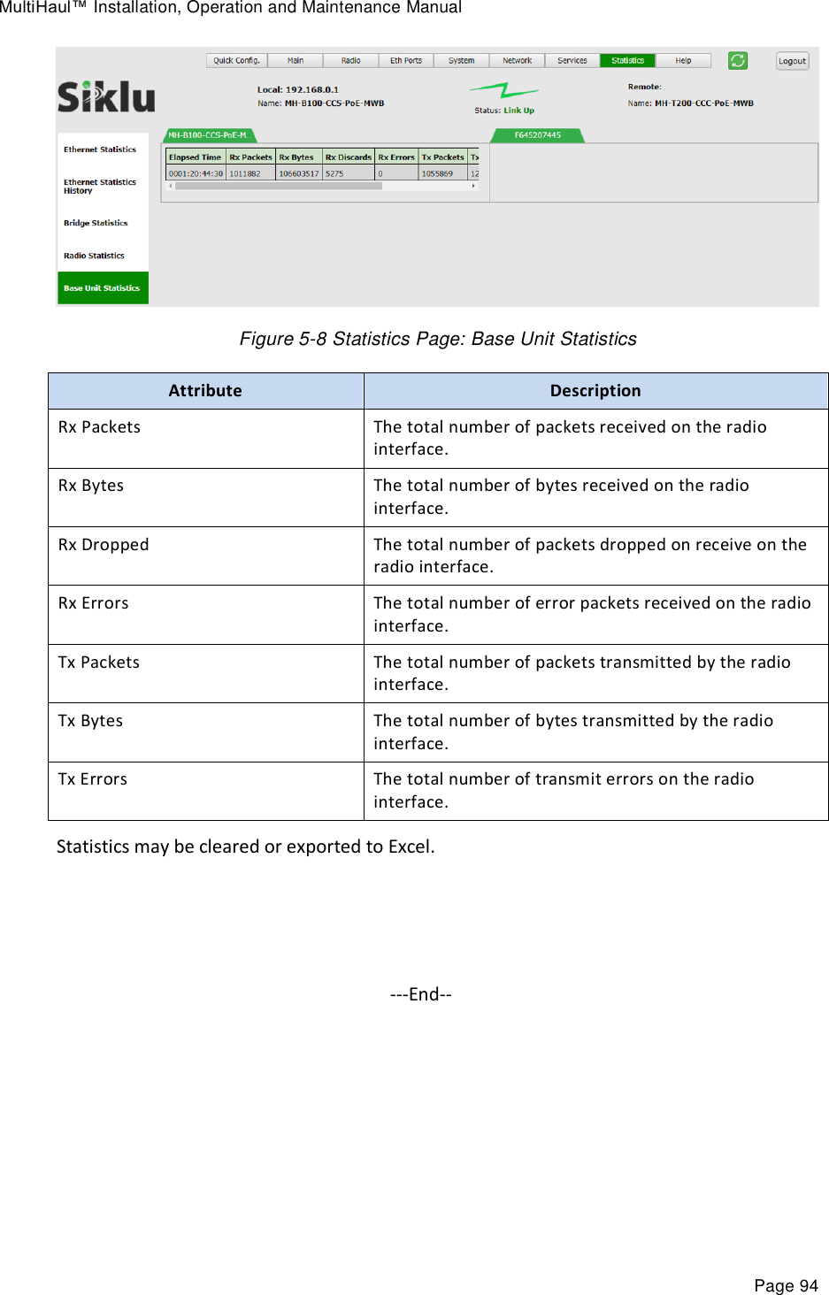
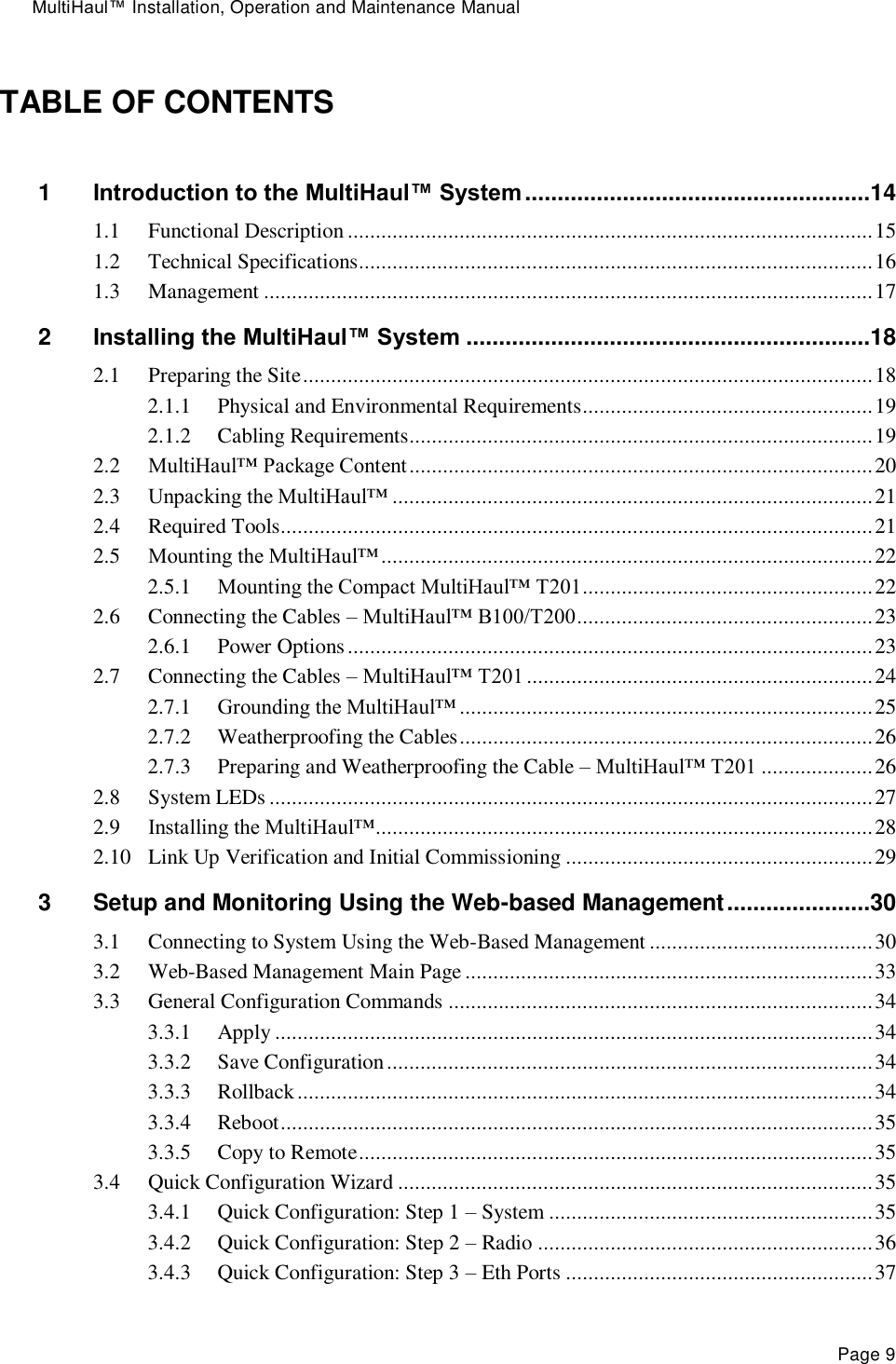
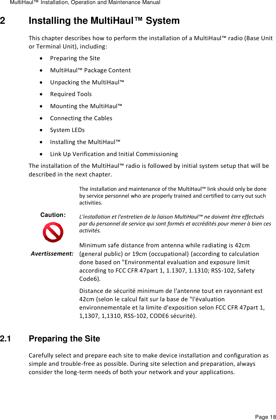
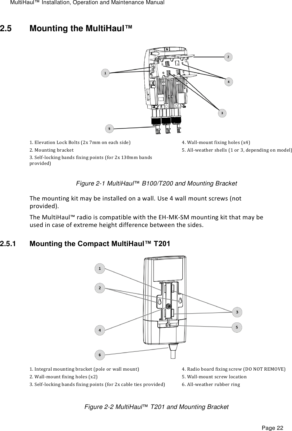
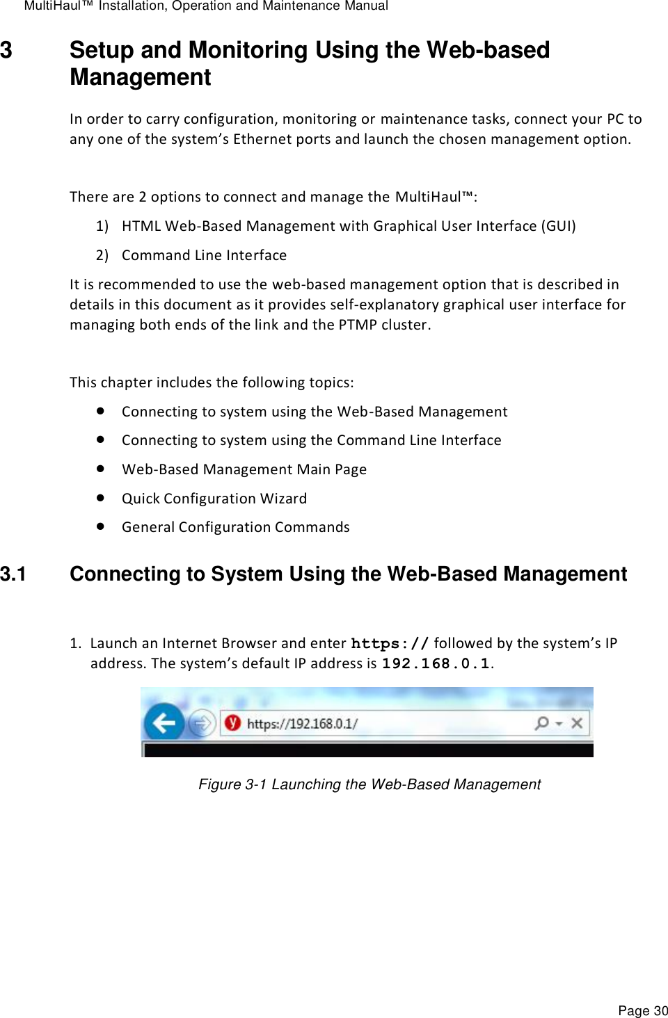
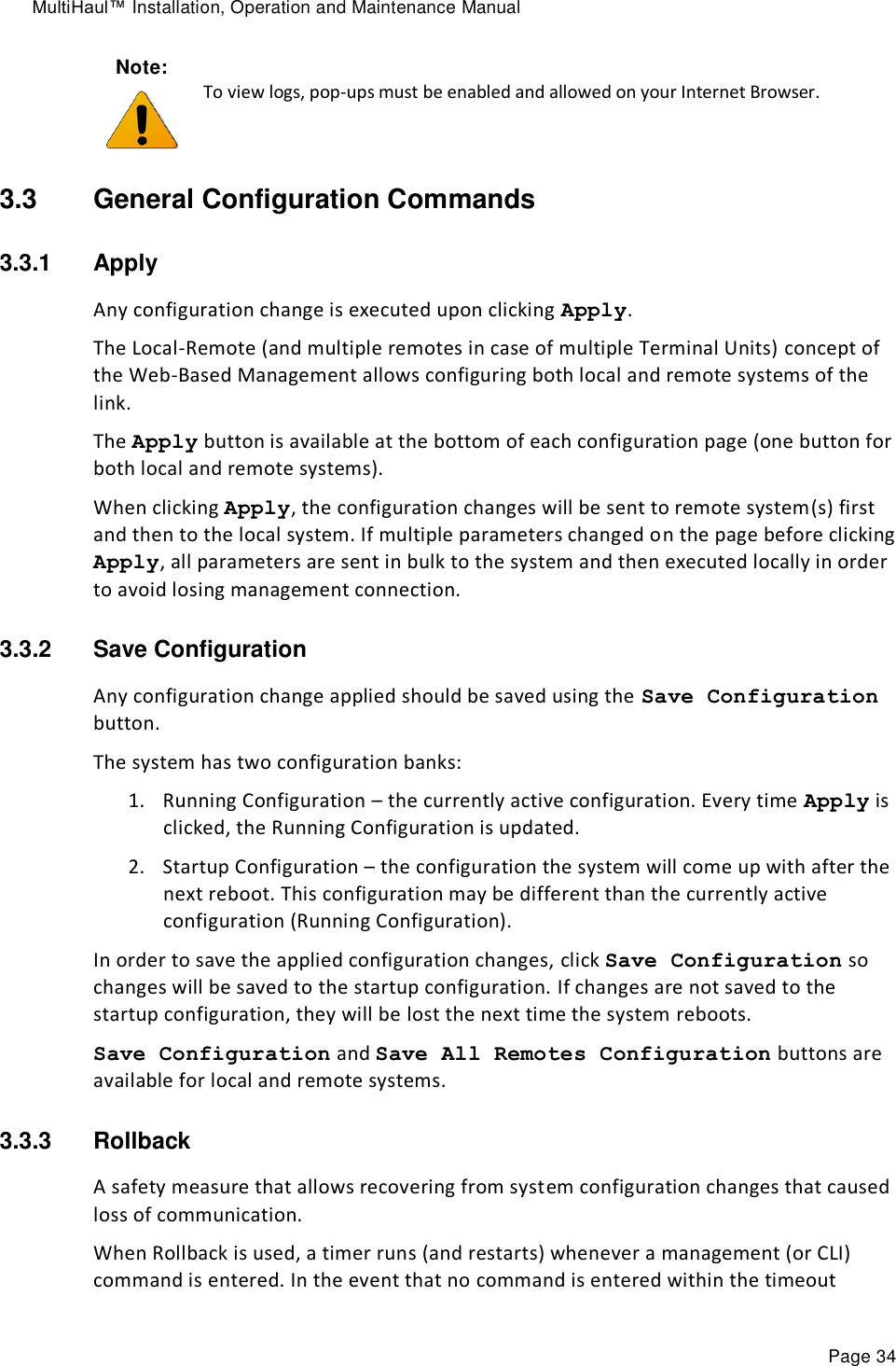
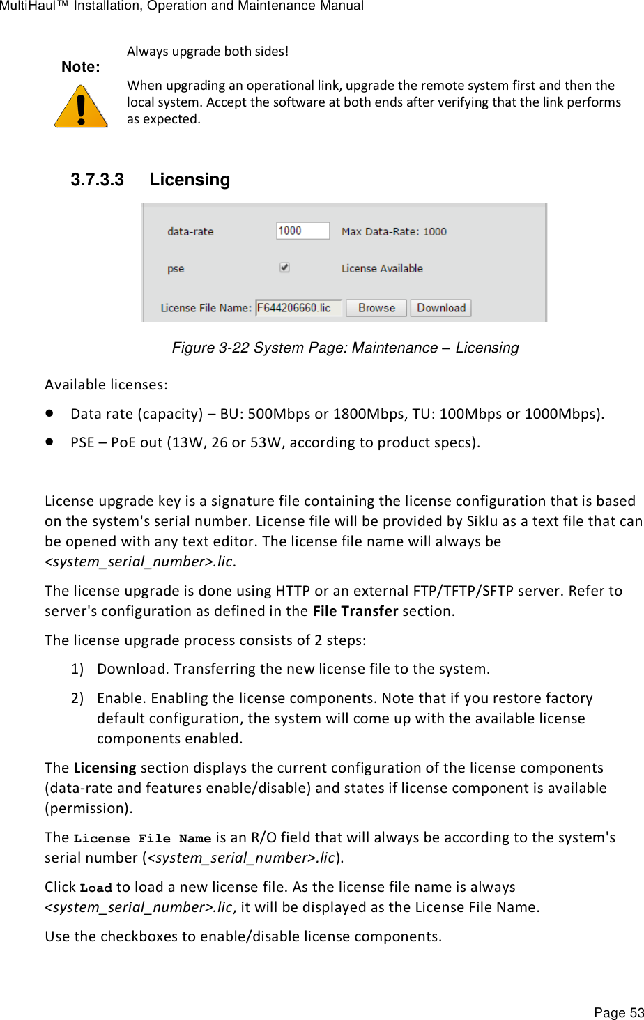
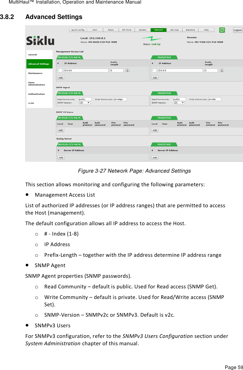
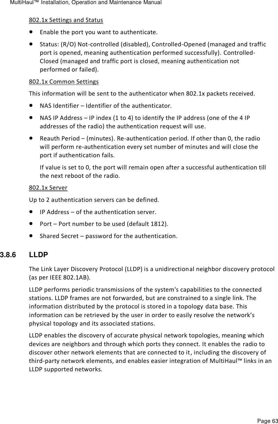
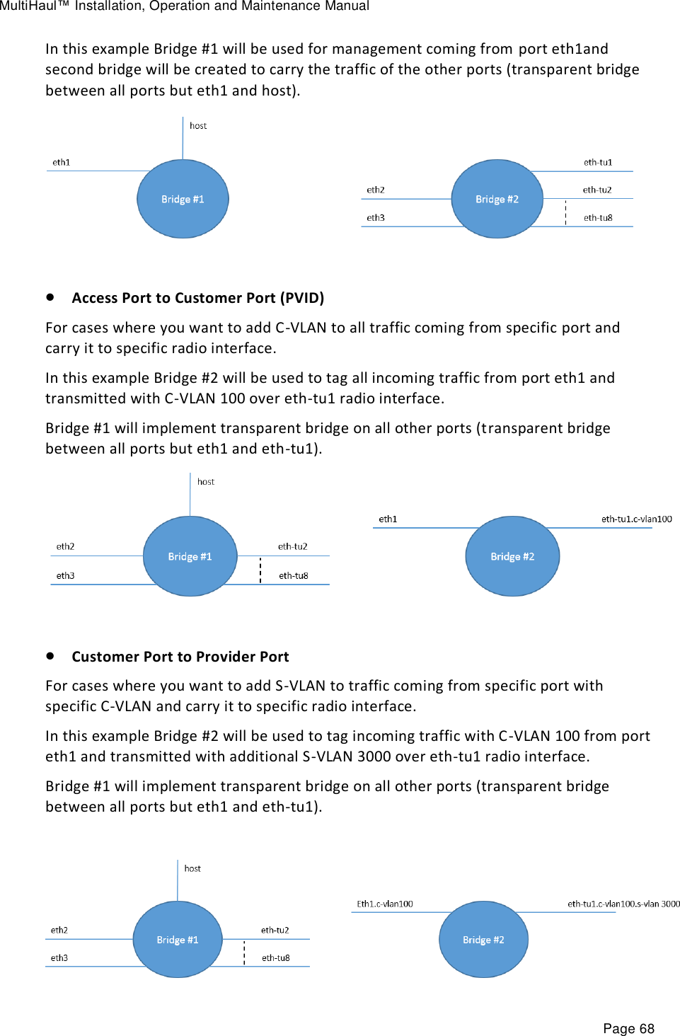
![MultiHaul™ Installation, Operation and Maintenance Manual Page 52 3.7.3.2 SW Upgrade Figure 3-21 System Page: Maintenance – SW Upgrade The system supports two software version, maintaining an Active (running) and an Offline (standby) software versions (banks) that allow software upgrade with minimum service interruption. The software upgrade process consists of 3 steps: 1) Download. Transferring the new software file to the system (to the offline software bank). 2) Upgrade. Switching the active status between the banks so the downloaded software becomes active. 3) Accept. Use timeout to verify that the new active software performs as expected and accept the upgrade to make it permanent. The SW Upgrade section displays the software versions currently resides in the banks and their status (Active or Offline). The software download is done using HTTP or an external FTP/TFTP/SFTP server. Refer to server's configuration as defined in the File Transfer section. This section allows configuring the following parameters: SW File Name – The name of the software file to download. Accept Timeout [Sec] – time out in seconds in which the new software should be accepted. If the new software is not accepted within the timeout period, the system will reboot and rollback to the previously active software. It is recommended to use 600 seconds timeout whenever upgrading a software. Click Download to start the software download from the server to the system. Click Upgrade to activate the downloaded software. This action will result in system reboot. Click Accept to accept the new SW.](https://usermanual.wiki/Siklu-Communication/SK-MH60CC-A1/User-Guide-4104670-Page-52.png)
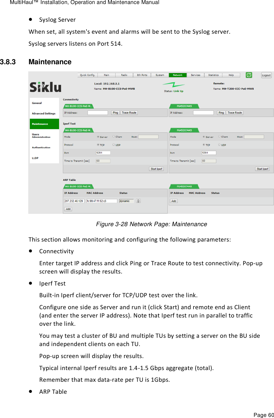
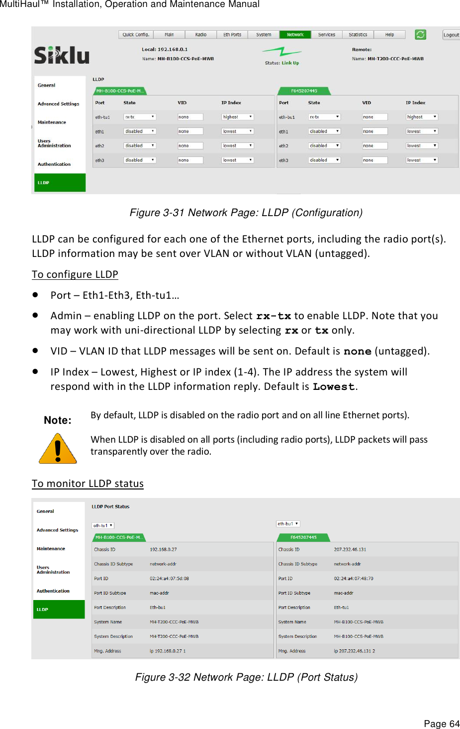

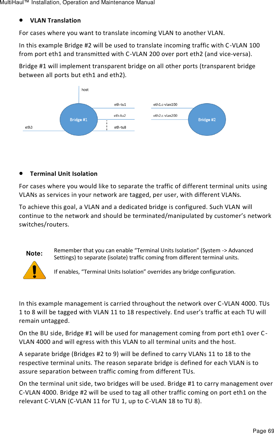
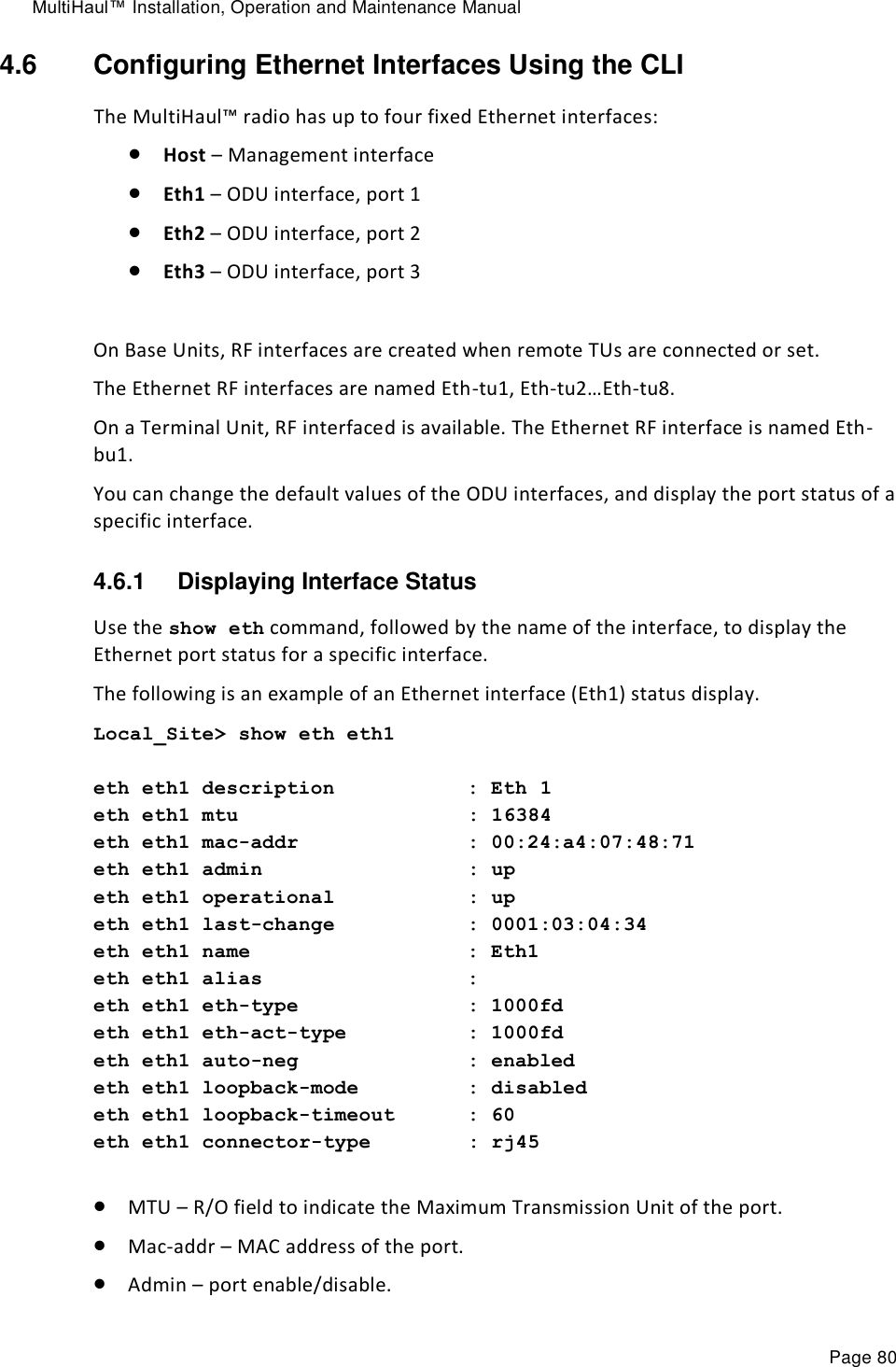
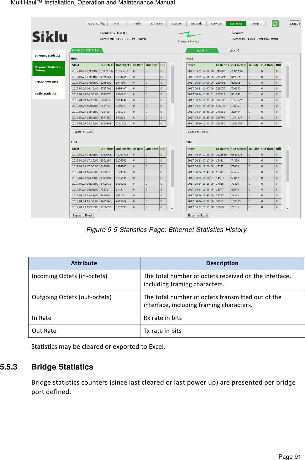
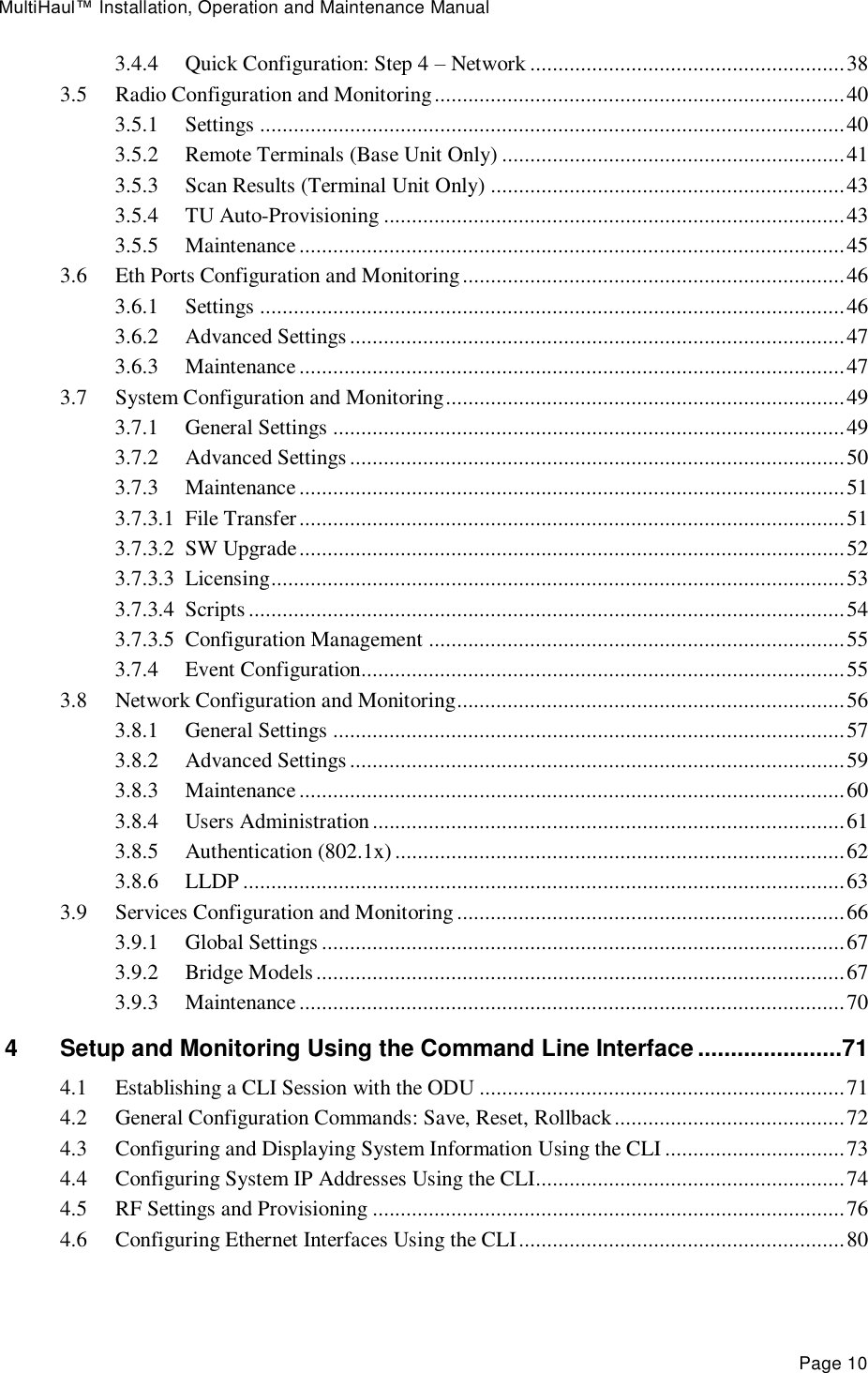
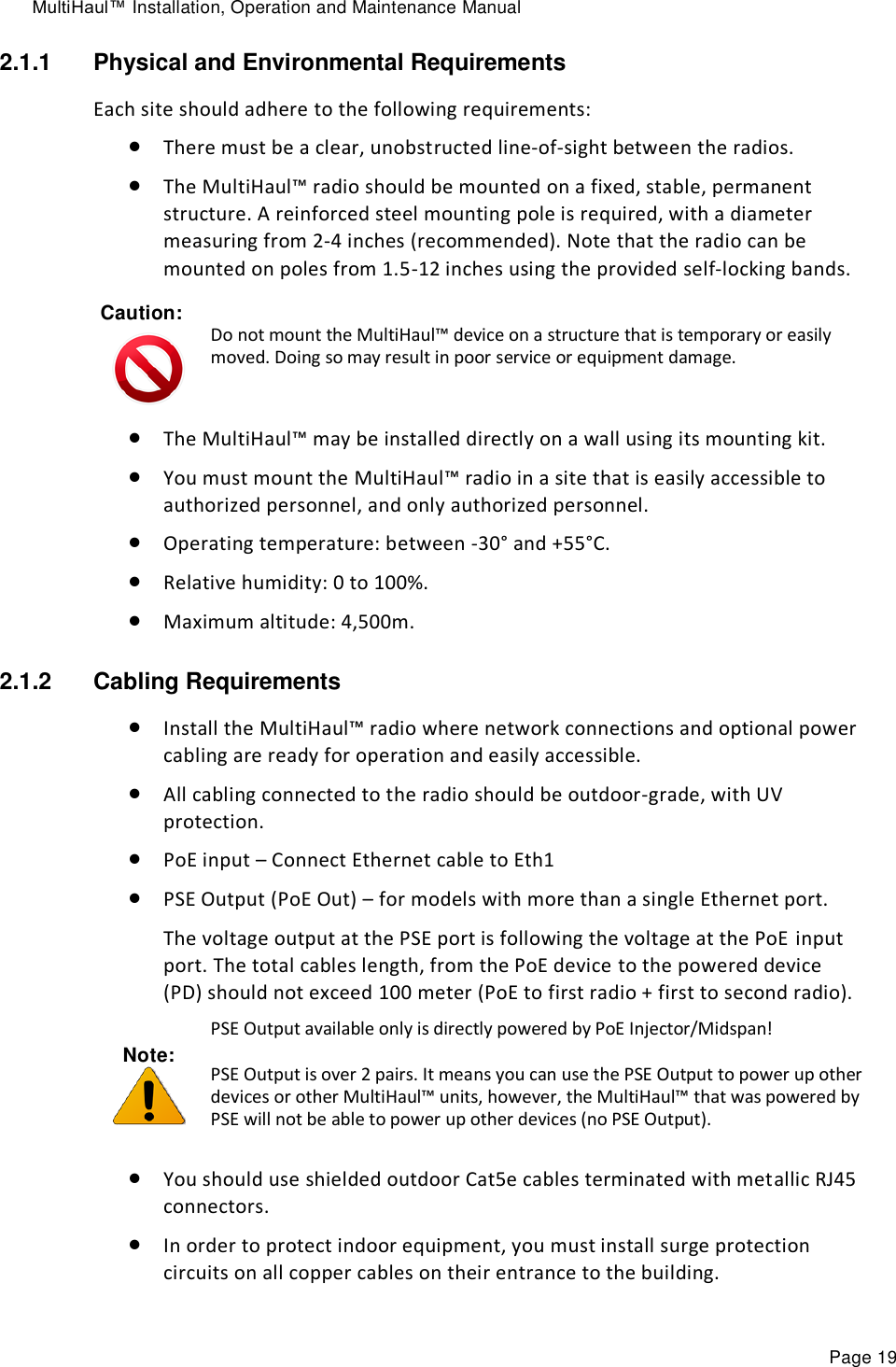
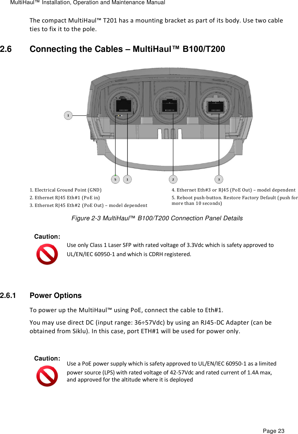
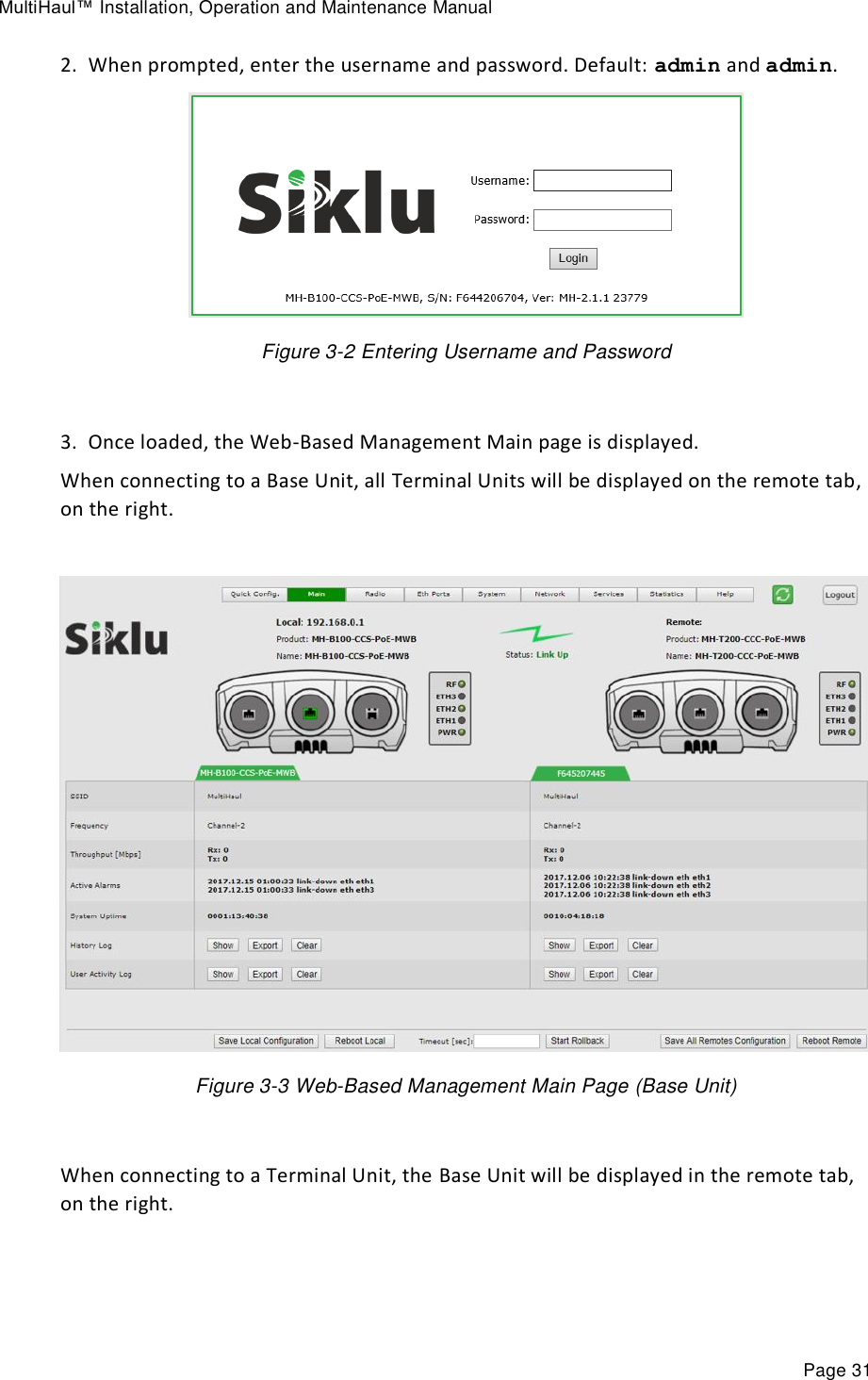
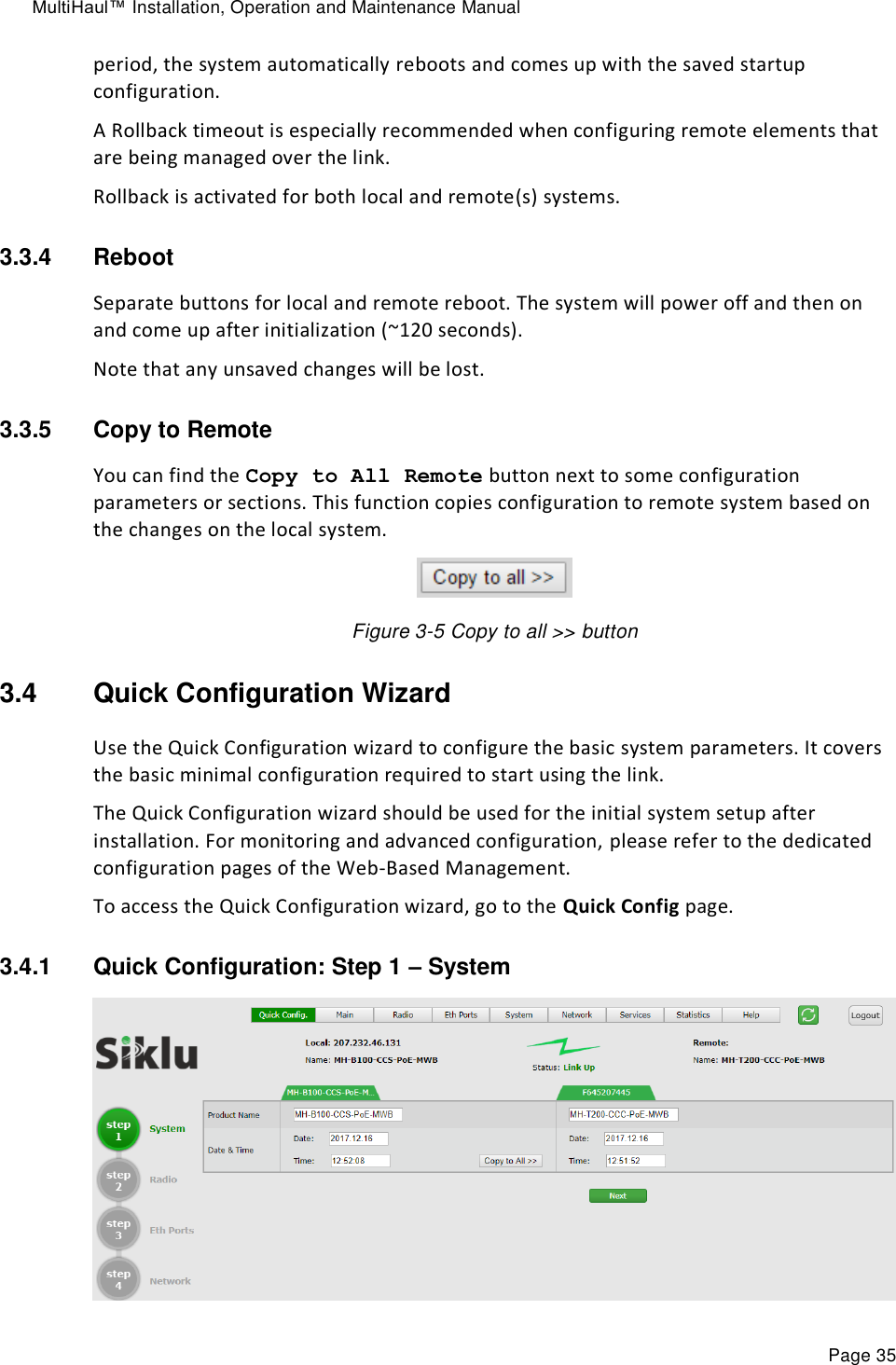
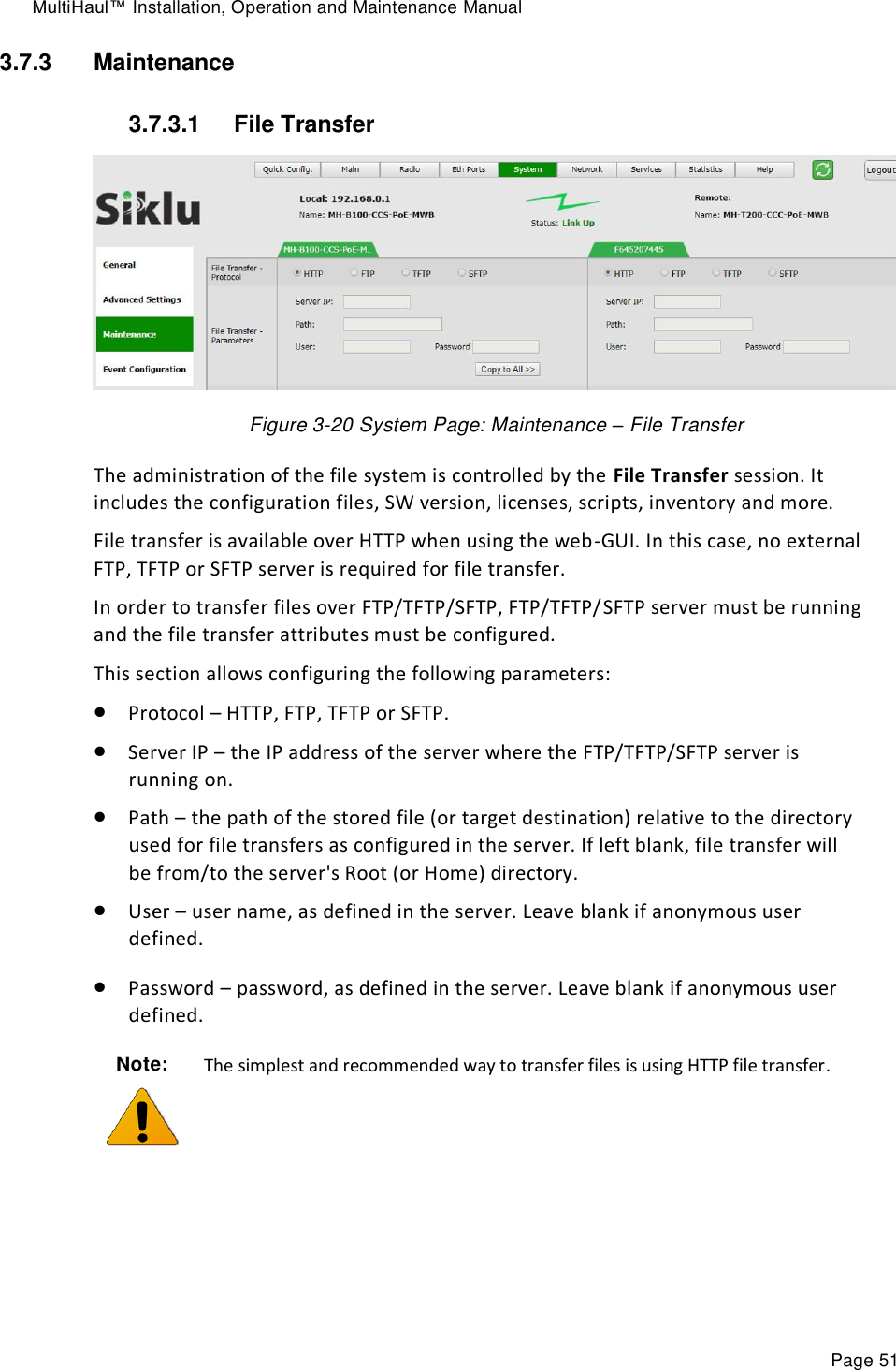
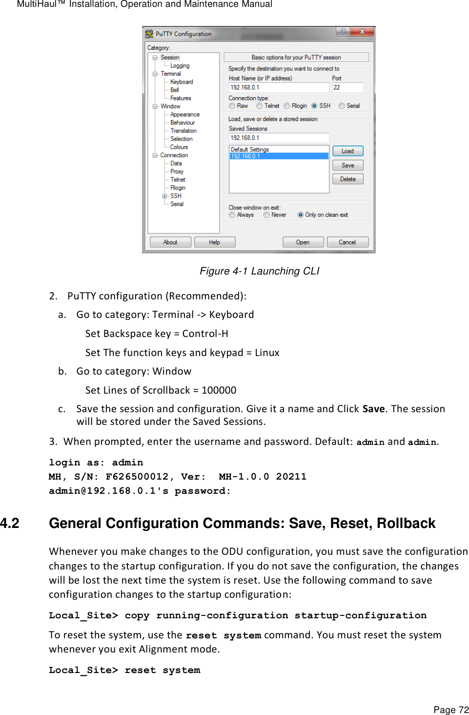
![MultiHaul™ Installation, Operation and Maintenance Manual Page 71 4 Setup and Monitoring Using the Command Line Interface This chapter explains how to perform basic configuration tasks using the Command Line Interface (CLI). The CLI provides interface for configuration and monitoring. Includes the entire configuration options of the system. General format of CLI command: command object <object-id(s)> [attribute-name <attribute-value>] for example: set eth eth1 eth-type 1000FD show eth all statistics Typical commands: Set, show, clear, reset, run, copy General CLI conventions: o Confirmation after each command correctly entered. o Error-message with hint in case of wrong command o Use Tab for Auto-complete o Use Up Arrow and Down Arrow to display command history o Use ? for help on possible configuration options and for exact command syntax. 4.1 Establishing a CLI Session with the ODU 1. Launch SSH client. You can use any common, open source SSH client program, such as PuTTY, available for download from the web. Open an SSH session to the system’s IP address. The system’s default IP address is 192.168.0.1.](https://usermanual.wiki/Siklu-Communication/SK-MH60CC-A1/User-Guide-4104670-Page-71.png)
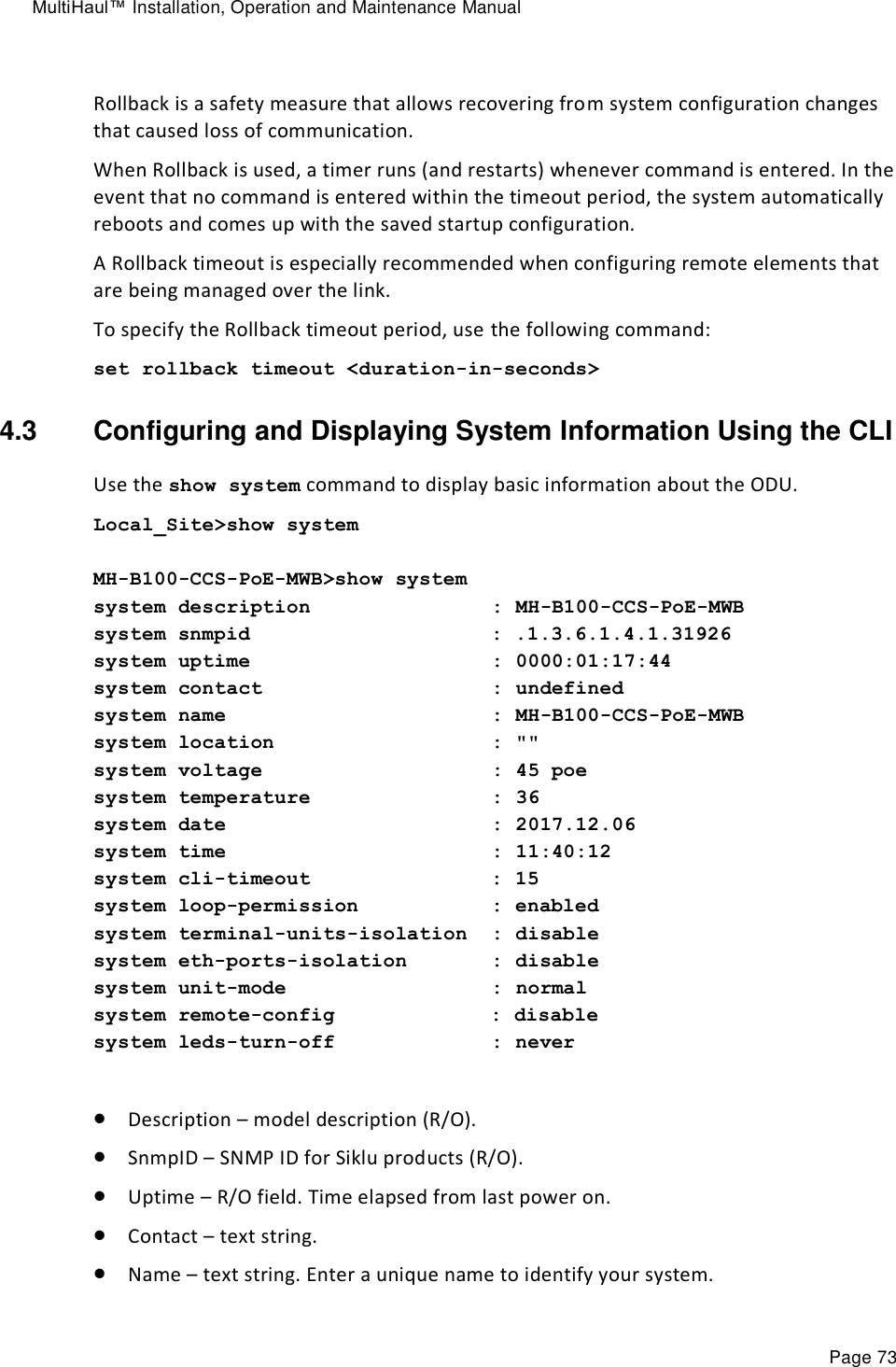
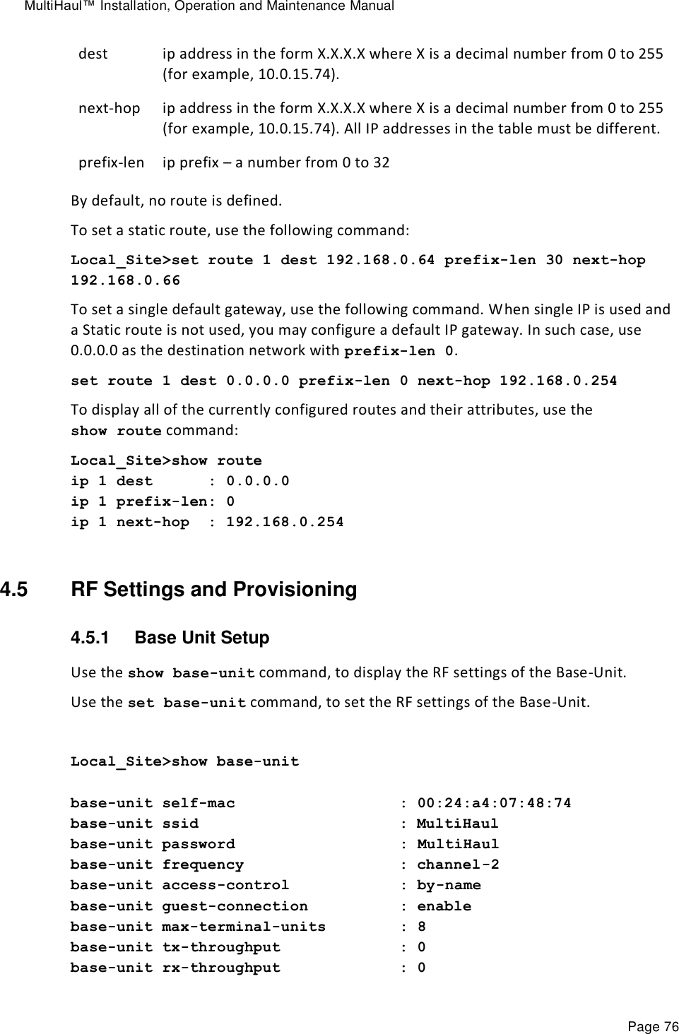
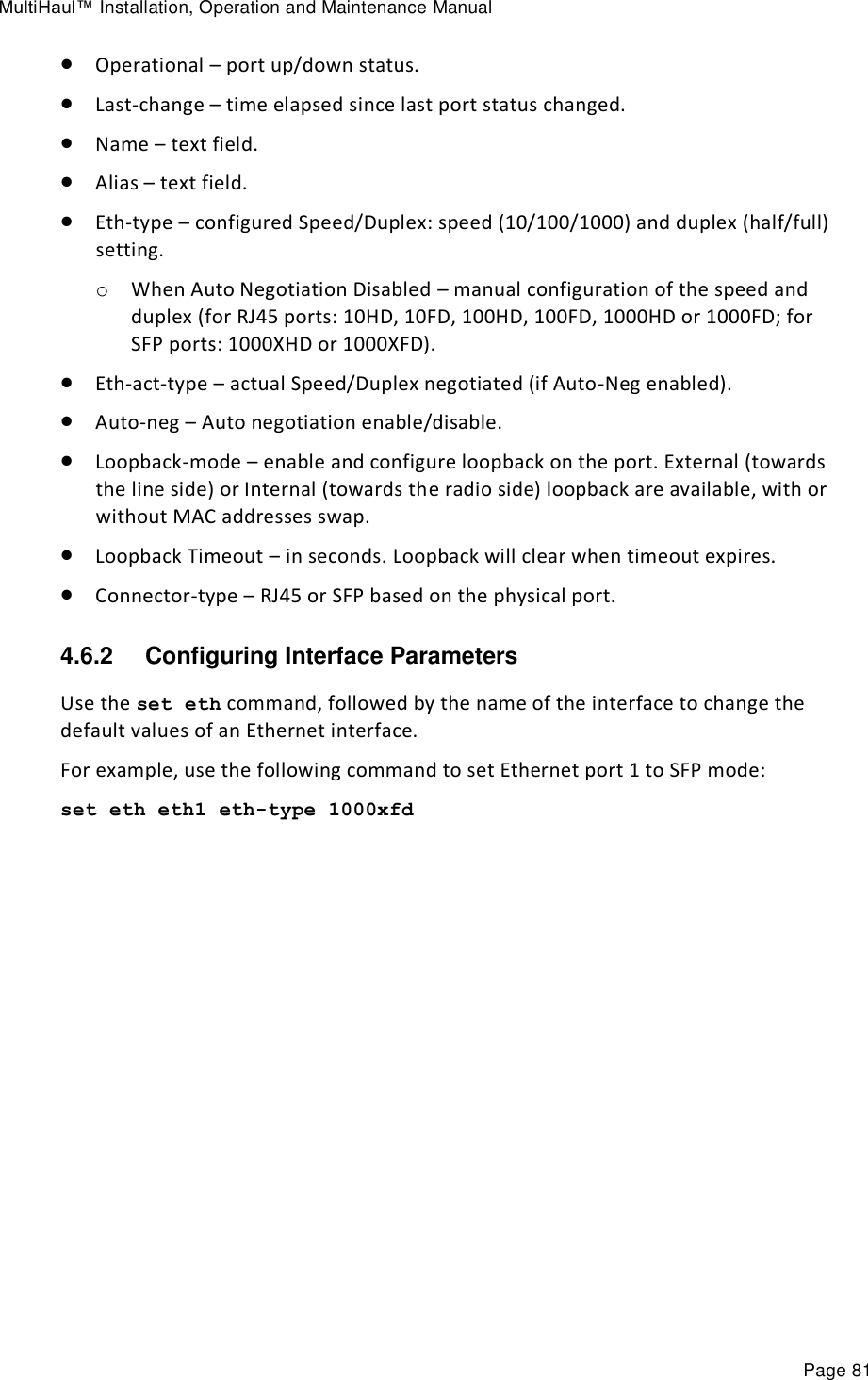
![MultiHaul™ Installation, Operation and Maintenance Manual Page 74 Location – text string. Voltage – input voltage and indication DC or PoE (R/O). Temperature – system temperature in C⁰ (R/O). Date & Time – Date [YYYY.MM.DD], Time [HH:MM:SS] Cli-timeout – timeout for auto-logoff. Loop Permission – control the permission to perform system loopbacks. Terminal units Isolation (Base Unit only) – when checked, packets coming from one TU and received by BU will not be transmitted to any other TU, isolation the traffic of each TU from neighboring TUs. Eth Ports Isolation – when checked, packets coming from one port of the radio will not be transmitted to any other ports of the TU (only towards the radio ports and the management host), isolation the traffic of each Eth port from other Eth ports. Unit Mode – Normal or Low-Power. Use Low-Power for bench testing only, when distance between radios is up to few meters. Default: Normal. Remote Config (Terminal Unit only) – enable auto-provisioning of TUs by BU. Default: Distabled. Leds Turn Off Time – when value entered (in minutes), the radio Leds will turn off automatically after the set time (up to 6000 minutes). To turn on the Leds, reboot the radio. If left blank, Leds will not turn off automatically (default). Use the set system name command to set the ODU’s name. Once you set the ODU’s name, a prompt appears with the name you just set, the date, and the time. Default> set system name Local_Site Local_Site> To set system date & time, use the following command: Local_Site> set system date 2017.12.13 time 15:08:00 4.4 Configuring System IP Addresses Using the CLI The MultiHaul™ radio supports up to four IP addresses that can be on different subnets and associated with different VLANs. You can assign a static route to each IP address. The Default IP-Gateway is defined as a static route. By default, one IP address is defined (IP #1): IP Address – 192.168.0.1 IP network Prefix – 24](https://usermanual.wiki/Siklu-Communication/SK-MH60CC-A1/User-Guide-4104670-Page-74.png)
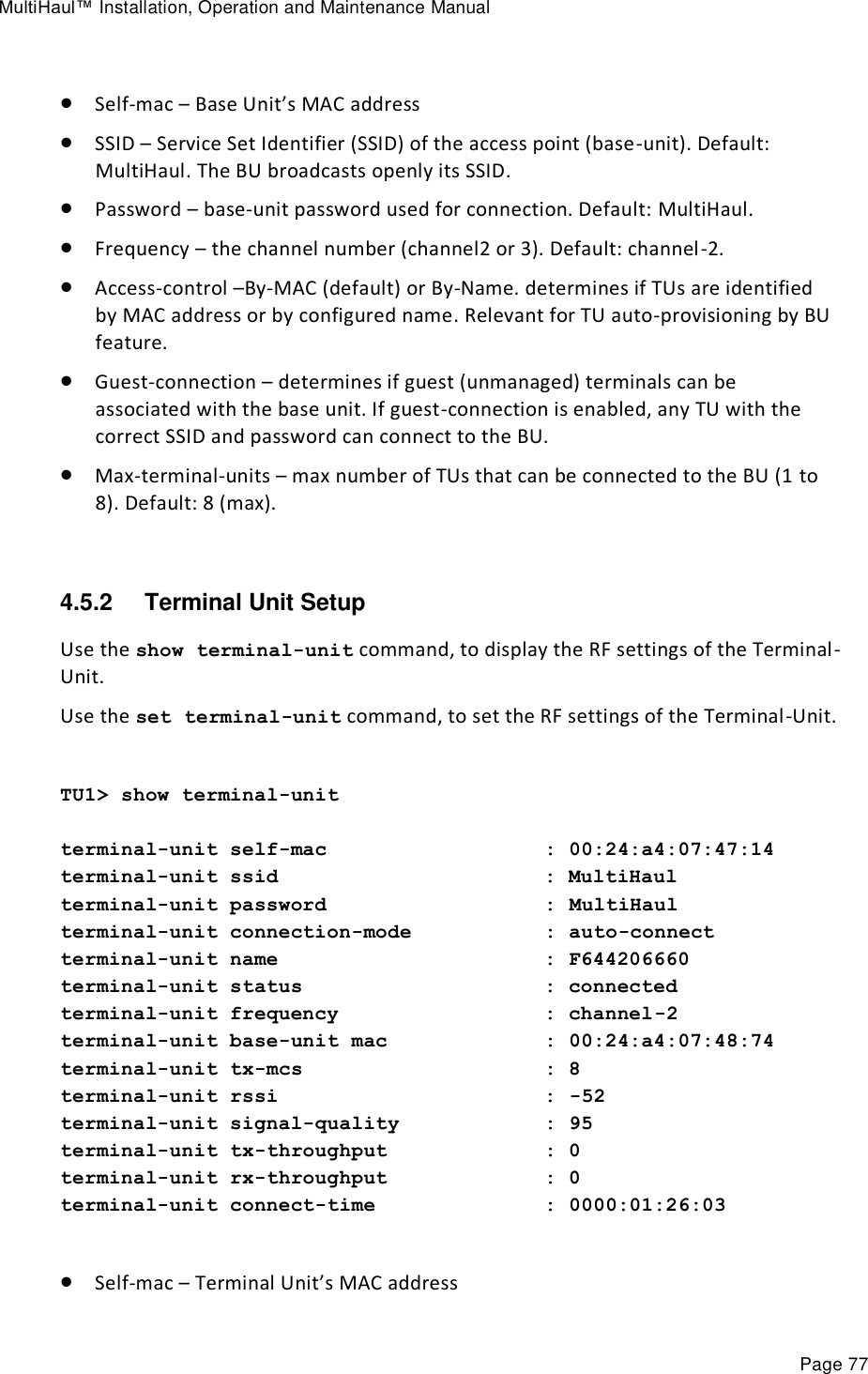
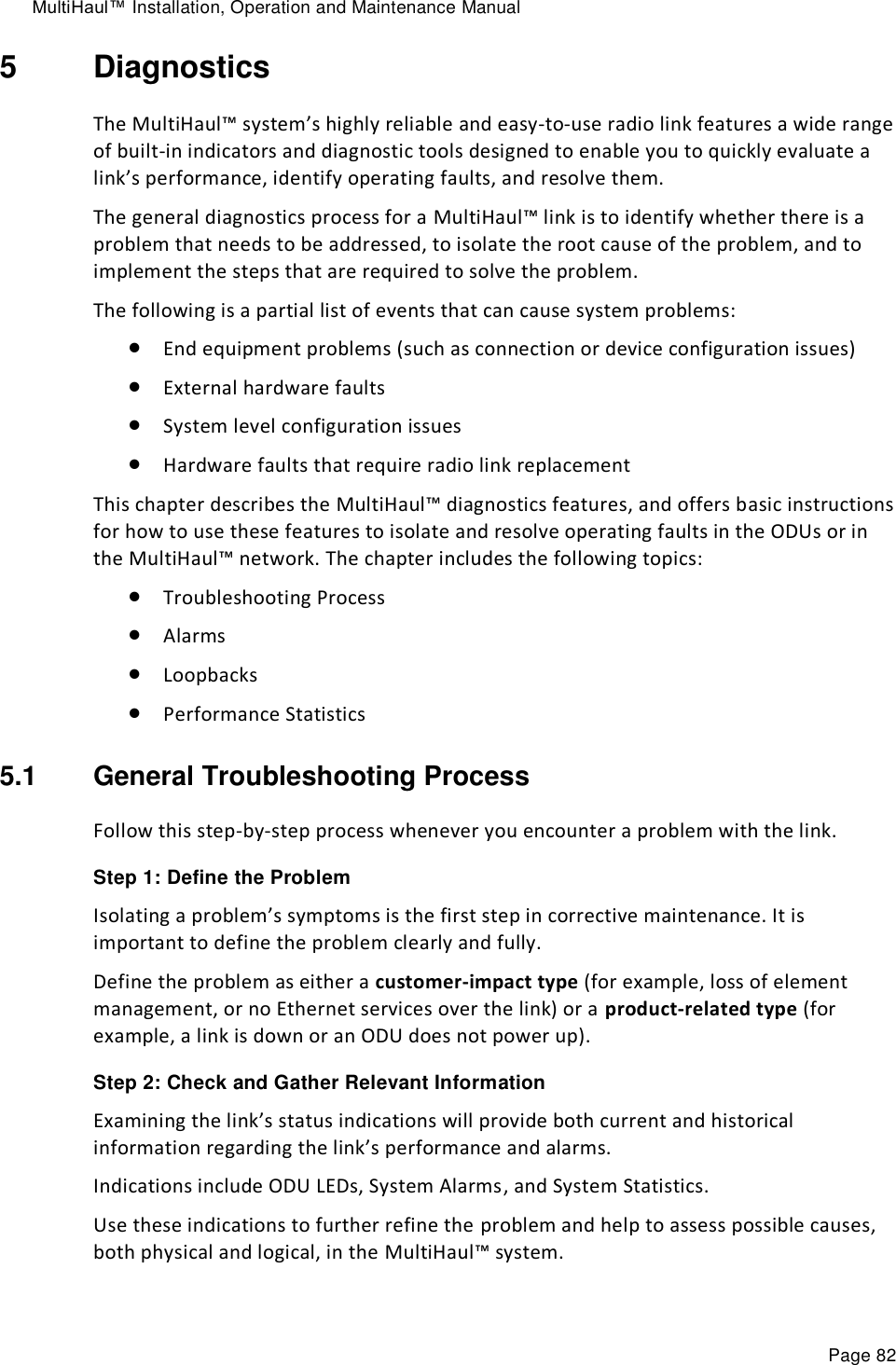
![MultiHaul™ Installation, Operation and Maintenance Manual Page 75 VLAN – 0 (not defined) Default Gateway – 0.0.0.0 (by default, no route is defined). Use the set ip command to change or add an IP address. The command must be followed by the index number of the IP address you want to add or change. Use the index number 1 to change the default IP address. For example: set ip <ip-index> ip-addr <value> [prefix-len <value>] [vlan <value>] <ip-index> : integer 1..4 Local_Site>set ip 1 ip-addr 192.168.0.11 prefix-len 24 If the IP entry does not already exist, the set ip command creates it and assigns the attributes specified. If the interface address or the default router address is not explicitly specified, the entry is created with the default value that has been defined for the VLAN. If the IP entry already exists, the set ip command replaces the attributes that are currently defined for the entry with the values specified in the command. Up to four IP addresses can be specified on the command line. A set ip command fails if the route specified is not within the subnet that has been defined by mask. Note: If you change the default IP address, your connection to the ODU will be lost. To re-establish a connection, launch an Internet browser and connect using the new IP address. To display all of the currently configured IP addresses and their attributes, use the show ip command: For example: Local_Site>show ip ip 1 ip-addr : 192.168.0.11 ip 1 prefix-len : 24 ip 1 vlan : 0 ip 1 default-gateway : 0.0.0.0 To delete IP entries, use the clear ip command: clear ip <index> To create and modify an IP Route and Default Gateway, use the set route command: set route <idx> [dest <ip-address>] [prefix-len 0..32] [next-hop <ip-address>] idx number 1 to 10](https://usermanual.wiki/Siklu-Communication/SK-MH60CC-A1/User-Guide-4104670-Page-75.png)