Silent Call Communications CO5SS418 418 MHz Periodic Transmitter for use in CO Detection User Manual 108182 CO5 SS indd
Silent Call Communications 418 MHz Periodic Transmitter for use in CO Detection 108182 CO5 SS indd
Manual
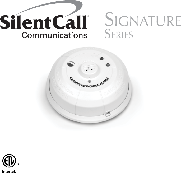
CARBON MONOXIDE DETECTOR
WITH BUILT IN WIRELESS TRANSMITTER
Installation and Operation Manual
Model # CO5-SS
418 MHZ TRANSMITTER
Document #
108182
3126052

GENERAL INFORMATION:
Before installing detectors, please thoroughly read these installation
instructions. For detailed information on detector spacing, placement,
zoning, wiring, and special applications refer to current edition of the
NFPA 72 National Fire Alarm and Signaling Code.
NOTICE: These instructions should be left with the owner/user of this
equipment.
IMPORTANT: This detector must be tested and maintained regularly
following NFPA 72 requirements. Test detector operation weekly. The
detector should be cleaned at least once a year.
NOTE: CO Detectors have a limited life. CO detectors should be replaced
immediately if not operating properly. You should always replace a CO
detector after 6 years from date of purchase.
NOTE: Remove battery tab before installation.
NOTE: Radio Frequency device operates at 418MHz
WARNING: This product is intended for use in ordinary indoor
locations of family living units. It is not designed to measure
compliance with Occupational Safety and Health Administration (OSHA)
commercial or industrial standards. Individuals with medical problems
may consider using warning devices which provide audible and visual
signals for carbon monoxide concentrations under 30ppm.
FCC ID: PPJCO5SS418

WHAT TO DO IF THE CARBON MONOXIDE DETECTOR GOES INTO
ALARM:
WARNING:
Activation of your CO alarm indicates the presence of Car-
bon Monoxide (CO) which can KILL YOU. If Alarm sounds:
1. Operate reset/silence button;
2. Call your emergency services (_____________________)
( re department or 911);
3. Immediately move to fresh air-outdoors or by an open
door/window. Do a head count to check that all persons
are accounted for. Do not re-enter the premises nor
move away from the open door/window until emergen-
cy services responders have arrived, the premises has
been aired out, and your alarm remains in its normal
condition.
4. After following steps 1-3, if your alarm reactivates with-
in 24 hour period, repeat steps 1-3 and call a quali ed
appliance technician(________________) to investigate for
sources of CO from fuel burning equipment and appli-
ances, and inspect for proper operation of this equip-
ment. If problems are identi ed during this inspection
have the equipment serviced immediately. Note any
combustion equipment not inspected by the technician

and consult the manufacturers’ instructions, or contact
the manufacturers directly, for more information about
CO safety and this equipment. Make sure that motor
vehicles are not, and have not been, operating in an at-
tached garage or adjacent to the residence.
IMPORTANT INFORMATION FOR THE USER:
CAUTION: This alarm will indicate the presence of carbon mon
oxide gas at the sensor. Carbon Monoxide gas may be present
in other areas.
WARNING: Carbon Monoxide Detector will not operate without
a serviceable battery. Inspect and replace your batteries at least
once a year to ensure proper working condition.
IMPORTANT: Constant exposures to high or low humidity may
reduce battery life. A good safety measures is to replace the
battery at least once a year, or at the same time you change
your clocks for daylight savings time.
WARNING: The installation of this device should not be used
as a substitute for proper installation, use and maintenance of
fuel burning appliances, including appropriate ventilation and
exhaust systems.
Carbon Monoxide Gas and its Detection
This carbon monoxide detector is designed for indoor use only. Do not
expose to rain or moisture. Do not knock or drop the detector. Do not
open or tamper with the detector as this could cause malfunction. The
detector will not protect against the risk of carbon monoxide poisoning
if not properly installed. The detector will only indicate the presence of
carbon monoxide gas at the sensor.
Carbon monoxide gas may be present in other areas. This carbon mon-
oxide detector is NOT:
• Designed to detect smoke, fi re or any gas other than carbon monox-
ide
• To be seen as a substitute for the proper servicing of fuel-burning
appliances or the sweeping of chimneys.
• To be used on an intermittent basis, or as a portable alarm for the
spillage of combustion products from fuel-burning appliances or
chimneys
Carbon monoxide gas is a highly poisonous gas which is released when
fuels are burned. It is invisible, has no smell and is therefore impos-
sible to detect with the human senses. Under normal conditions in a
room where fuel burning appliances are well maintained and correctly
ventilated, the amount of carbon monoxide released into the room by
appliances should not be dangerous.
SYMPTOMS OF CO POISIONING:
Carbon Monoxide (CO) is an insidious poison. Carbon monoxide bonds
to the hemoglobin in the blood and reduces the amount of oxygen
being circulated in the body. It is a cumulative poison. Even low levels
of CO have been shown to cause brain and other vital organ damage in
unborn infants with no effect on the mother.
The following symptoms are related to CARBON MONOXIDE POISON-
ING and should be discussed with ALL members of the household:
Mild exposure:
Medium exposure:
Extreme exposure:
Many causes of reported CARBON MONOXIDE POISONING indicate
that while victims are aware that they are not well, they become so
disoriented that they are unable to save themselves by either exiting the
building or calling for assistance.
Also young children and pets may be the fi rst to be affected. You should
take extra precautions to protect high risk persons from CO exposure
because they may experience ill effects from CO at levels that would not
ordinarily affect a heathy adult.
Slight-Headache, nausea, vomiting, fatigue (often
described as “fl u-like symptoms).
Severe throbbing headache, drowsiness, confusion,
fast heart rate.
Unconsciousness, convulsions, cardio-respiratory
failure, death.
SOURCES OF CARBON MONOXIDE:
Home appliances used for cooking and heating are the most common
household Carbon Monoxide sources. Vehicles running in an attached
garage can also produce dangerous levels of CO. Burning any fossil fuel
including gasoline, propane, natural gas, oil, and wood can produce
Carbon Monoxide. It can be produced when any heating or cooking
appliance is not installed properly, vented correctly, or malfunctioning.
CO producing appliances include furnace, hot water heaters, gas range/
stove, gas dryer, fuel burning space heaters, generators, vehicles, fi re-
places, blocked chimney/vents and grills.
CONDITIONS WHICH CAN RESULT IN TEMPORARY CO SITUATIONS:
1. Excessive spillage or reverse venting of fuel burning appliances
caused by:
i. Outdoor ambient conditions such as wind direction
and/or velocity, including high gusts of wind; heavy air
in the vent pipes(cold humid air with extended periods
between cycles).
ii. Negative pressure differential resulting from the use of
exhaust fans.
iii. Simultaneous operation of several fuel burning applica
tions competing for limited internal air.
iv. Vent pipe connection vibrating loose from clothes dry
ers, furnaces, or water heaters.
v. Obstructions in or unconventional vent pipe designs
which amplify the above situations.
2. Extended operation of unvented fuel burning devices (range,
oven, fi replace, etc.).
3. Temperature inversions which can trap exhaust gases near the
ground.
4. Car idling in an open or closed attached garage, or near a home.
GENERAL DESCRIPTION:
The CO5-SS is a 3V battery powered Carbon Monoxide (CO) detector
with a built in wireless transmitter intended for use with Silent Call
418MHz Signature Series SK2-SS and WC08-SS Receivers.
The detector consists of an electrochemical carbon monoxide sensor
assembly coupled to a wireless transmitter. The transmitter can send
alarm messages to the Silent Call receivers. Refer to the Receiver sys-
tem instructions for the CO alert details. The CO5-SS CO detector will
alert the Silent Call Receiver only during a CO Alarm. Please refer to
Maintenance Section for Low battery and End of Life conditions.
The transmitter signal incorporates a digital addressable coding system
that is preset at the manufacturer.
IMPORTANT: The range and proper operation of any wireless device
will vary depending on its surroundings. It is very important that each
CO5-SS detector is tested with each receiver intended for alarm.
Detector Description
• LIsted to UL Standard 2034
• CO sensitivity is evaluated to UL 2034
• Local sounder
• Dual LED’s
• Test/Hush button
• Functional Gas Test
• Surface mount to wall or ceiling
• Optional drywall anchors included
The CO5-SS contains a piezoelectric horn which generates the ANSI
S3.41 temporal 4 pattern in an alarm condition (see note below Table
1 for temporal 4 pattern). In alarm, a message is also sent to a pro-
grammed Silent Call Receiver. The alarm message is transmitted every
4 seconds until the carbon monoxide condition has cleared and the de-
tector has reset. During an alarm condition, pressing the detector’s test
button will silence the piezoelectric horn for fi ve minutes. The mounting
base installation is simplifi ed by the incorporation of features compat-
ible with drywall fasteners or other methods that provide a method for
securing the detector in place.
Two LEDs and a sounder on the detector provide local visual and audi-
ble indication of the detector’s status as listed in Table 1.

During initial power-up, the red and green LEDs will blink together once
every 10 seconds four times. It takes about 30 seconds for the detector’s
CO sensor to stabilize (see Table 1).
After power-up has completed and the detector is functioning normally,
the green LED blinks once every 10 seconds. The LED indication must
not be used in place of the tests specifi ed under
TESTING THE DETECTOR.
Table 1: Detector LED Modes
Chirp every 45 sec
beginning
7 days a er LED blinks,
con nues 30 days
Sounder
Off
Temporal 4 Pa ern†
One Chirp every 45
seconds
Off
Off
Temporal 4 Pa ern†
Red LED
Off
Blinks every 1 second
Blinks every 45 seconds
for 37 days
Blinks every 5 seconds
Blinks every 10 seconds
Blinks every 10 secs ††
(w/green LED)
One Chirp every 45
seconds
Off
Blinks every 1 second
Green LED
Blinks every 10 seconds
Off
Off
Off
Off
Off
Blinks every 10 secs ††
(w/red LED)
Blinks every 1 second
Normal
(Standby)
Alarm/Test
Low Ba ery
Dectector Trouble
Dectector End-of-Life
Power Up
Func onal Gas Test
(A er Co is Sprayed)
† Temp 4 pattern is repeated pattern of four short beeps followed by a fi ve second pause.
If ambient conditions return to normal, the detector will self-restore out of alarm and into
the previous mode.
†† Red and green LEDs blink a total of four times, once every 10 seconds
Hush feature: If required, the audible alarm can be silenced for fi ve
minutes by pushing the Test button. The red alarm light will continue
to fl ash in temp-4 pattern. If carbon monoxide is still present after the
5-minute hush period, the audible alarm will sound. The hush feature
will not operate at levels above 350 ppm (parts per million) carbon mon-
oxide.
Trouble feature: When the sensor is in a trouble condition. The red LED
blinks once every fi ve seconds. Trouble conditions include an open
circuit, sensor removal (tamper), and sensor end of life. See Table 1 for
LED and sounder mode.
End of Life Timer feature: When the detector has reached the end of its
life, the LED will blink, this indicates that the CO sensor inside the detec-
tor has passed the end of its life and the detector must be replaced. This
detector’s lifespan is approximately six years from the date of manufac-
ture. Refer to Detector Replacement section. See Table 1 above for LED
and sounder mode.
Low Battery Detection: The CO5-SS is powered by a single 3-volt
CR123A Lithium battery. The red LED of the detector will blink every 45
seconds. After 7 days the detector’s horn will “chirp” about every 45
seconds (red LED continues to blink) for up to 30 days. Pressing the test
button during this time will silence the chirps for 12 hours, if no other
trouble conditions exist. The battery should be replaced BEFORE the
chirps begin. Be sure to replace the battery with a fresh one.
BATTERY INSTALLATION AND REPLACEMENT:
You can purchase a new 3 volt Panasonic CR123A or Duracell DL123A at
many different local retail stores or directly from Silent Call Communi-
cations by calling 1-800-572-5227, or online at www.silentcall.com.
To replace the battery:
1. Remove the detector from its mounting base by twisting the detec-
tor counterclockwise. Remove the battery and dispose of properly.
2. To ensure proper power-down sequence, wait a minimum of 20
seconds before installing new battery.
3. Install a new 3-volt CR123A Lithium battery in the battery compart-
ment. Follow the polarity diagram inside the compartment.
4. Reinstall the detector onto the mounting base by turning the detec-
tor clockwise.
5. Test the detector as described in the TESTING SIGNAL STRENGTH
section of this manual. The green LED should blink about once
every 10 seconds to indicate normal operation. If the battery is not
installed correctly, the detector will not operate and the battery may
be damaged. If the detector does not appear to be sending a signal
during any of the tests, check for correct battery installation and for
a fully charged battery.
T
E
S
T
H
U
S
H
N
O
R
M
A
L
A
L
A
R
M
D
O
N
O
T
P
A
I
N
T
C
A
U
T
I
O
N
:
A
D
D
I
T
I
O
N
A
L
M
A
R
K
I
N
G
S
O
N
B
A
C
K
C
A
R
B
O
N
M
O
N
O
X
I
D
E
D
E
T
E
C
T
P
R
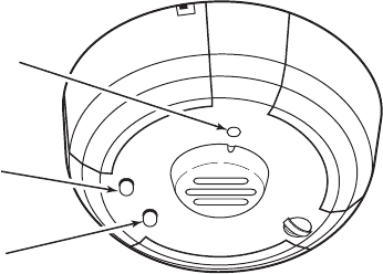
TEST BUTTON
GREEN LED
RED LED
5800CO-001-V0
Figure 1: CO5-SS Wireless Carbon Monoxide Detector
CO5-SS Wireless Smoke detector will be addressed at manufacturer to
Code L. You can change address due to possible cross talk between like
systems. Battery must be reset for new address to resister. Note: Dip
switches all ON or all OFF is NOT a valid address.
Refer to your Signature Receiver Installation Operation Manual for
programming instructions.
MOUNTING THE DETECTOR:
First, determine the best location for the detector, one that provides
proper carbon monoxide detection (see Figure 4 for suggested detec-
tion locations) and a strong wireless transmission path.
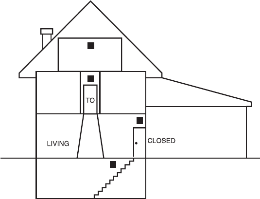
Proper Carbon Monoxide Detection Location:
On a wall location, the detector should be at least as high as a light
switch, and at least six inches from the ceiling. In a ceiling location, the
detector should be at least 12 inches from any wall.
Where to install, ideally:
• Within 10 feet of all sleeping areas
• Inside the bedroom if it contains a fuel burning appliance
• On every fl oor of the building
• Ideally, install in any room that contains a fuel burning appliance
• If the appliance in the room is not normally used, such as the boiler
room, the detector should be placed just outside the room so the
alarm can be heard more easily
Where NOT to install, ideally:
• Detectors operate best if not installed within 5 feet of any cooking
appliance Outside
• Directly above a sink, cooker, stove or oven Next to a door or win-
dow that would be affected by drafts i.e. extractor fan or air vent
• Do not install in any environment that does not comply with the
detector’s environmental specifi cations
• In or below a cupboard
• Where air fl ow would be obstructed by curtains or furniture
• Where dirt or dust could collect and block the sensor
• Where it could be knocked, damaged, or inadvertently removed
Good Transmission Path:
A good transmission path must be established from the proposed
mounting location before permanently installing the detector. To check,
perform the test described in the testing signal strength section.
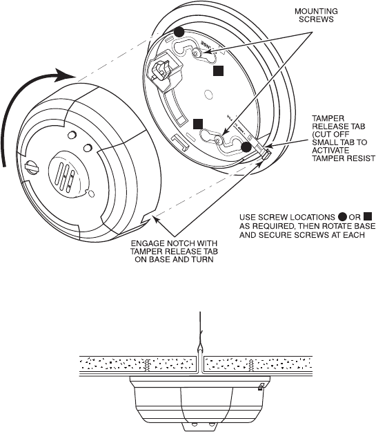
Mounting Procedure:
Once a suitable location is found, mount the detector as follows:
1. Refer to the diagram below and install the mounting base on the
ceiling or on the wall (if local ordinances permit) using screw lo-
cations “A” or “B” as required. Use the two screws and anchors
provided. Maneuver the base so the screws are at the elbow of the
screw slots and secure.
2. Fit the detector inside the base by aligning it over the base as shown
(detector’s alignment notch should be slightly offset from mounting
base tamper release tab), then turn the detector in a clockwise direc-
tion until it clicks into place.
3. Test the detector after completing the installation (as described in
the TESTING THE DETECTOR section of this manual) and refer to
the control system’s instructions for additional information concern-
ing the use of wireless devices.
5800CO-006-V0
LOCK
TAMPER LOCK
FEATURE)
NOTE
MOUNTING SLOT'S ELBOW.
CLOCKWISE TO LOCK
(INSTALLED)
D
O
N
O
T
P
A
I
N
T
B
A
B
B
A
A
T
E
S
T
H
U
S
H
N
O
R
M
A
L
A
L
A
R
M
C
A
R
B
O
N
M
O
N
O
X
I
D
E
D
E
T
E
C
T
O
R
W
A
R
N
I
N
G
:
I
N
A
L
A
R
M
M
O
V
E
T
O
Figure 2. Mounting the Detector
Figure 3. Mount Detector Across Ceiling Panel Support
5800CO-003-V0
DO NOT attach the detector to removable ceiling panels. Attach the
detector across panel support as shown in Figure 3.
CAUTION:
Airborne dust particles can enter the detector. Manufacturer recom-
mends the removal of detectors before beginning construction or any
other dust producing activity. Carbon monoxide detectors are not to be
used with detector guards unless the combination has been evaluated
and found suitable for that purpose.
CARBON MONOXIDE ALARM LOCATION FOR MULTI-LEVEL RESIDENCE
Figure 4. Detector Location Diagram
ROOM
BEDROOM BEDROOM
BEDROOM
KITCHEN
BR
DOOR
BASEMENT
GARAGE

Tamper Protection:
The CO5-SS detector includes a tamper-resistant feature that prevents
removal from the mounting base without the use of a tool. To engage
the tamper-resistant feature, cut the small plastic tab located on the
mounting base (Figure 2), and then install the detector. To remove the
detector from the base once it has been made tamper resistant, use a
small screwdriver to depress the square tamper release tab, located on
the skirt of the mounting base, and turn the detector counterclockwise.
TESTING THE DETECTOR:
NOTE: Remove battery tab before installation
NOTE: Before testing, notify the occupants that the detector system is
undergoing maintenance, in order to prevent unwanted alarms. Testing
the detector will activate an alarm and send a signal to the Silent Call
receiver. Also, the test function cannot be used if the detector has a
trouble or end-of-life condition. The manufacturer cannot recommend a
specifi c agent with which to test the detector. Detectors must be tested
after installation and following periodic maintenance.
T
E
S
T
H
U
S
H
D
O
N
O
T
P
A
I
N
T
N
O
R
M
A
L
A
L
A
R
M
C
A
R
B
O
N
M
O
N
O
X
I
D
E
D
E
T
E
C
T
O
R
W
A
R
N
I
N
G
:
I
N
A
L
A
R
M
M
O
V
E
T
O
F
R
E
S
H
A
I
R
C
A
U
T
I
O
N
:
A
D
D
I
T
I
O
N
A
L
M
A
R
K
I
N
G
S
O
N
B
A
C
K
LEDs
BUTTON
REFERENCE TABLE 1 for LED indication Mode defi nitions. Using a 1/8
diameter tool press and release the Test /Hush button. If the Detector is
operating properly you will hear 4 quick beeps followed by 5 seconds of
silence, followed by 4 more quick beeps. Red Led Blinks once a second
between Temporal patterns. After second beep CO detector will reset
back to Normal (standby) mode. It may take up to 30 seconds for CO
detector to properly reset and be ready to retest when programming
Silent Call receivers.
Testing Signal Strength:
This test should be performed before installation to determine a strong
communication path with the Silent Call Receiver and after installation
is complete. Also, the owner/user should test the unit’s signal strength
at least weekly.
1. Have someone monitor the Receiver you wish to alert.
2. Depress and hold the detector’s TEST/Hush button. If the detector
has not previously detected a low battery condition and it is within
proper sensitivity limits, the detector should immediately transmit
an alarm signal to the receiver. The built-in horn will start to sound
about 2.5 seconds after depressing the button.
3. The Silent Call Receiver shall annunciate a CO Alert in accordance
with specifi c receiver used.
4. When the Silent Call Receiver has received the test signal, release
the TEST button. The horn will stop and approximately 16 seconds
after releasing the test switch the receiver will stop alerting CO.
5. If the receiver does not respond as noted, check the polarity of the
battery and be sure it is fresh. If this is an initial installation, try
rotating the detector or moving the detector to another location that
provides proper reception. Also be sure that the detector has been
programmed and tested to the receiver in use.
FUNCTIONAL GAS TEST
The CO5-SS has a functional gas test mode which can be used to verify
the detector’s ability to sense carbon monoxide gas.
NOTE: Check with local codes and the AHJ to determine whether or not
a functional gas test is desired for an installation.
A canned CO testing agent may be used to verify the [model #] ability
to sense CO by utilizing the functional gas test mode. To perform the
functional gas test, follow these steps:
1. With a small screwdriver, depress and hold the recessed “Test”
switch for approximately 2 seconds. The detector will temporarily
go into alarm and the red LED will illuminate.
2. Within a few seconds the green LED will start to blink rapidly indi-
cating the detector is in a speed up, functional test mode awaiting
gas entry.
3. Spray a very small amount of Solo brand C6 canned CO into one of
the 3 small gas entry holes located on the top center of the detector.
4. Upon successful gas entry and if functioning properly, the detector
will alarm by sounding in a Temporal 4 pattern with the red LED
blinking. An alarm signal will be sent to the Silent Call Receiver
providing verifi cation of alarm signal.
5. The alarm condition at the detector will time out in 20 to 60 seconds
or when the CO gas has cleared.
6. If gas entry is unsuccessful, the test will time out after 27 seconds.
MAINTENANCE:
It is recommended to Test and visually inspect the CO alarm Once a
week. Replace CR123A Battery at least once a year to ensure proper
operation of all the CO5-SS functions. Make Note of the Replace CO
detector by Date. CO detector has a life span of six years max.
Occasionally clean the outside casing with a clean dry cloth. Ensure that
the holes on the front of the alarm are not blocked with dirt and dust.
Do not paint, and do not use cleaning agents, bleach, or polish on the
detector.
IMPORTANT: REGULAR TESTING IS RECOMMENDED.
DETECTOR REPLACEMENT
This detector is manufactured with a long-life carbon monoxide sensor.
Over time the sensor will lose sensitivity, and will need to be replaced
with a new carbon monoxide detector. This detector’s lifespan is ap-
proximately six years from the date of manufacture.
The user should periodically check the detector’s replacement date.
Remove the detector from its base and check the replacement date label
on the underside of the detector. The label indicates the date that the
detector should be replaced.
NOTE: The detector will also cause a trouble condition once it has
reached the end of its useful life. If this occurs, it is time to replace the
detector.
NOTE: Before replacing the detector, test unit to Silent Call receiver to
ensure proper operation.
CO Technology Limitations:
The CO5-SS utilizes an electrochemical CO sensing element, and there-
fore has certain performance limitations. The CO sensing element has a
typical life of 6 years from the date of manufacture, and while the prod-
uct has a timer to create a trouble condition after 6 years of operating,
the date code of the product, rather than the timer, should determine
when the product is replaced. The CO sensing element has a carbon fi l-
ter that provides resistance to false alarms caused by cross-interference
gasses, but the fi lter can be saturated, and so the product should not
be installed in locations where high concentrations of these gasses are
present. Cross-interference gasses include, but are not limited to: Meth-
ane, Butane, Heptane, Ethyl Acetate, Isopropyl Alcohol, Carbon Dioxide,
Ammonia, Ethanol, Toluene, Trichloroethane, and Acetone. Only a cloth
moistened with water should be used to clean the CO5-SS housing.
The movement of gases into the sensing element can be impaired if a
sealant blocks the porous surface of the CO sensor. The CO5-SS should
not be exposed to aerosol products such as furniture polish, paint or
varnish that can coat the CO sensing element and render it inoperative.
FCC INFORMATION NOTICE:
Unauthorized changes or modifi cations could void the user’s authority
to operate the equipment.
This device complies with Part 15 of the FCC Rules. Operation is subject
to the following two conditions: (1) This device maynot cause harmful
interference, and (2) this device must accept any interference received,
including interference that may cause undesired operation of the device.
This equipment has been tested and found to comply with the limits
for a Class B digital device, pursuant to Part 15 of FCC Rules. These
limits are designed to provide reasonable protection against harmful
interference in a residential installation. This equipment generates, uses
and can radiate radio frequency energy and if not installed and used
in accordance with the instructions, may cause harmful interference to
radio communications. However, there is no guarantee that interference
will not occur in a
particular installation. If this equipment does cause harmful interference
to radio or television reception, which can be determined by turning the
equipment off and on, the user is encouraged to try to correct the
interference by one or more of the following measures:
• Reorient or relocate the receiving antenna.
• Increase the separation between the equipment and the receiver
• Connect the equipment into an outlet on a circuit different from that
to which thereceiver is connected.
• Consult the dealer or an experienced radio/television technician for
help

Specifi cations
Power Source:
Audible Signal (temp 4 tone):
Height:
Diameter:
Weight:
Operating Ambient Temperature Range:
Operating Humidity Range:
Agency Listings:
One 3-volt CR123A Lithium Battery (included).
(Replace with Panasonic CR123A or DURACELL
DL123A)
These batteries are available at local retail stores.
You can also order Replacement Batteries Online
at www.Silentcall.com.
85 dBA min. in alarm (at 10ft)
2.3 inches (58 mm)
5.3 inches (135 mm) (with mounting base)
7 oz. (241 g) (without battery)
40° to 100°F (4.4° to 37.8°C)
15% to 95% Relative Humidity, non-condensing
Conforms to ANSI/UL STD 2034
For Warranty Claims/Repairs Please Contact the Manufacturer:
Silent Call Communications
5095 Williams Lake Road
Waterford, MI 48329
800-572-5227
Please Visit www.Silentcall.com