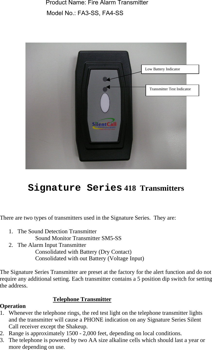
Silent Call Communications SCXMIT08 Fire Alarm Transmitter User Manual UserMan TX

Silent Call Communications Fire Alarm Transmitter UserMan TX

UserMan TX

   Signature Series 418  Transmitters    There are two types of transmitters used in the Signature Series.  They are:   1.  The Sound Detection Transmitter Sound Monitor Transmitter SM5-SS 2.  The Alarm Input Transmitter Consolidated with Battery (Dry Contact) Consolidated with out Battery (Voltage Input)  The Signature Series Transmitter are preset at the factory for the alert function and do not require any additional setting. Each transmitter contains a 5 position dip switch for setting the address.   Telephone Transmitter Operation 1.  Whenever the telephone rings, the red test light on the telephone transmitter lights and the transmitter will cause a PHONE indication on any Signature Series Silent Call receiver except the Shakeup. 2.  Range is approximately 1500 - 2,000 feet, depending on local conditions.   3.  The telephone is powered by two AA size alkaline cells which should last a year or more depending on use.    Low Battery Indicator Transmitter Test Indicator Product Name: Fire Alarm TransmitterModel No.: FA3-SS, FA4-SS
     Dry Contact Style Transmitters with Batteries Weather Transmitter   Carbon Monoxide CO3-SS   Door Access / Window Transmitter DW3-SS   Fire Transmitter FA3-SS   TransMATTer MAT-SS    Doorbell Transmitter w/button DB2-SS  Operation 1.  The Dry Contact Transmitters will transmit as long as the contact closure is made maintaining the alert output and will stop transmitting when the alert output goes back to normal or standby condition.   2.  Range is approximately 1500 - 2,000 feet, depending on local conditions.   3.  This unit is powered by two AA size alkaline cells.  Actual battery life is determined by the amount of time the transmitter is transmitting and amount of transmissions.  In normal use the batteries may be expected to last several years.  However, it is recommended the batteries be checked once a year.   Weather Transmitter   Carbon Monoxide CO3-SS   Door Access / Window Transmitter DW3-SS   Fire Transmitter FA3-SS   TransMATTer MAT-SS    Doorbell Transmitter w/button DB2-SS  Transmitters without Batteries Operation 4.  The Transmitters without batteries (voltage input) will transmit as long as the input voltage is present and above approximately 10VDC.  If connected to the horn / strobe line of a fire or security panel, it will transmit as long as the horn is activated or sounding.   5.  When transmitting, the Voltage Input Transmitter will result in the appropriate LED and ICON indication on the Signature Series  Silent Call receiver.   6.  Range is approximately 1500 - 2,000 feet, depending on local conditions.   7.  The Voltage Input Transmitters are powered by the input voltage and do not require a battery.     Voltage Input Transmitter Fire Panel Transmitter FA4-SS Direct Wired Doorbell Transmitter DB1-SS Carbon Monoxide Transmitter CO4-SS
 The Alarm Input Transmitters uses external connections for detection and transmission of the alarm signal such as, a Switch Closure, Telephone Line Ring Detection, Doorbell Chime Connection (Direct Wired Doorbell), or Fire Control Panel Connection.   The Sound Monitor Transmitter uses its internal sound monitoring circuit for the detection of audible alarms such as Smoke, Fire, CO, Telephone, Baby, Doorbell or other audible alarms.  The sound detection circuit has a built-in circuit that looks for an alarm or noise level over the ambient noise levels such as people talking, dog barking, radio or television, or instantaneous sounds which are often considered to be nuisance type sounds.  Notice the 3 position dip switch. This switch is used for setting the Sound Monitor for the particular type of sound detection you desire to be detected.  The Signature Series Transmitters also have an state of the art technology built in low battery detection circuit.  When operated from a battery (two AA’s) the transmitter monitors its own battery condition and will transmit a low battery signal to the receiver if the batteries reach a depleting voltage level or critical point.    An additional added feature of the Signature Series  418 transmitters are the Smoke and Fire Transmitter settings resulting in Supervisory Mode Transmission.  Both transmitters, when in the Fire or Smoke alarm setting, will automatically transmit a supervisory signal every two minutes.  This supervisory signal includes the transmitter address, the supervisory code plus the battery condition (low or ok).  All units capable of receiving the 418/433 transmissions contain microprocessor controlled software that detects the low battery signal.  The microprocessor software also detects the time intervals of the Fire or Smoke signal and resets an internal timeout.  If a signal has not been received within a ten minute period, the receiver will alert the end user to check the fire or smoke alarm signal path by displaying the CHK & Fire Icon on  the receiver .  A supervisor signal turning on the CHK & FIRE ICON can be a result of no signal being received due to:  1.  Battery is too low in transmitter to transmit 2.  Transmitter is out of range of the receiver 3.  A signal fault may lie between the transmitter and receiver.  For example if the receiver were moved from its original location and placed in a location that is not within the transmitters signal path.  Once the transmitters and receivers are setup and operating properly, they should remain in their designated locations.  TESTING AND PROGRAMMING YOUR TRANSMITTERS WITH THE SIGNATURE SERIES SIDEKICK  Apply power to the Sidekick.  Set the time
Plug-in the external vibrator or telephone cables if desired.  All Fire and smoke detector transmitters should be programmed first! Please refer to the instructions included with your Signature Series Sidekick receiver.   Turn on the transmitter.  Within a range of one or two feet from the Sidekick:  On the Sidekick press the mode button.  A flashing display with the letters PPP indicates that the Sidekick is ready to receive as well as the Yellow LED 3 will light.  Press the transmitter button, the Sidekick should show that the alarm signal has been received and displays the alarm icon (for example the door).  The Sidekick and Transmitter are now programmed.   Place the Transmitter as close to the audible alarm as possible (no more than several inches away).  Press the transmitter button, the Sidekick should respond. If the transmitter doesn’t respond, try locating the transmitter in another position or location.   Once a signal has been successfully received, test the transmitter again for proper operation.  The receiver should detect the transmitter again and light up the appropriate LED and ICON on the Sidekick.  The red light on the transmitter will indicate if the signal has been sent. All alert signals received by the Signature Series Sidekick will time out in 15 seconds provided the transmitting signal has ceased.     Sound Monitor Transmitter  The Sound Detection Transmitter operates from two standard AA Alkaline batteries with an expected battery life of more than one year.   The dip switch settings contain: 5 settings for address.  The address range is from 1 to 32.  Address 0 should not be used.  There are 3 settings for alarm detection mode.  The alarm detection  mode settings are:   0 Pager 1 Sound 2 Phone 3 Door 4 CO 5 Weather 6 Fire
7 Not used  NOTE:  The switch settings are set prior to turning on the power.  Any tampering with the switch settings after power has been applied will not alter the address or alarm mode of the transmitter.   The transmitter is ready to detect and send an alarm once the switch settings have been made and power applied (ON/OFF switch turned ON).   The Sound Monitor Transmitter will send an alarm based on two conditions:  1.  The test pushbutton is pressed or 2.  An audible alarm is detected.   LOCATION OF THE TRANSMITTER:  Once the dip switch settings have been set and the unit is turned on:   The Sound Monitor Transmitter should be located within several inches of the audible alarm you wish to detect (no more than 6” away).  The antenna should be rotated to a vertical position.   TESTING THE TRANSMITTER:  On units with battery, press the transmitter test pushbutton.  A red light should appear indicating that the transmitter has transmitted a signal.  The length of time of the signal is 2 seconds.  The receiver should indicate the alarm received by displaying the proper ICON and LED. On Voltage Input units when applying power to the transmitter, a red light should appear indicating that the transmitter has transmitted a signal as soon as power is applied. The length of time of the signal is 2 seconds.  The receiver should indicate the alarm received by displaying the proper ICON and LED.   Technical Support For technical support on this or any other Silent Call product, please feel free to contact us.  You can reach us by phone at 800-572-5227 (voice or TTY) or by Email at support@silentcall.com  Limited Warranty Your transmitter is warranted to be free of defects in material and workmanship for five years from the date of initial purchase.  During that time, the unit will be repaired or replaced free of charge when shipped prepaid to Silent Call Communications.  To obtain warranty service, contact Silent Call to obtain a return material authorization.  This warranty is void if the defect is caused by customer abuse or neglect.
  Federal Communication Commission Interference Statement This equipment has been tested and found to comply with the limits for a Class B digital device, pursuant to Part 15 of the FCC Rules. These limits are designed to provide reasonable protection against harmful interference in a residential installation. This equipment generates, uses and can radiate radio frequency energy and, if not installed and used in accordance with the instructions, may cause harmful interference to radio communications. However, there is no guarantee that interference will not occur in a particular installation. If this equipment does cause harmful interference to radio or television reception, which can be determined by turning the equipment off and on, the user is encouraged to try to correct the interference by one of the following measures: • Reorient or relocate the receiving antenna. • Increase the separation between the equipment and receiver. • Connect the equipment into an outlet on a circuit different from that to which the receiver is connected. • Consult the dealer or an experienced radio/TV technician for help. This device complies with Part 15 of the FCC Rules. Operation is subject to the following two conditions: (1) This device may not cause harmful interference, and (2) this device must accept any interference received, including interference that may cause undesired operation. FCC Caution: Any changes or modifications not expressly approved by the party responsible for compliance could void the user's authority to operate this equipment.

Navigation menu