Silent Call Communications SD4418SC Photoelectronic Smoke Detector with Built-in Wireless Transmitter User Manual
Silent Call Communications Photoelectronic Smoke Detector with Built-in Wireless Transmitter Users Manual
Users Manual
PHOTOELECTRONIC SMOKE DETECTOR
WITH BUILT-IN WIRELESS TRANSMITTER
Installation and Operation Manual
Model # SD4-MC(US)
418 MHZ TRANSMITTER
Document #
1081373126052
General Information
Before installing detectors, please thoroughly read these installation
instructions. For detailed information on detector spacing, placement,
zoning, wiring, and special applications refer to current edition of the
NFPA 72 National Fire Alarm Signaling Code.
NOTICE: Do not discard this manual. Manual should be left with the
owner/user of this equipment.
IMPORTANT: This detector must be tested and maintained regularly fol-
lowing NFPA requirements. Test detector operation weekly. The detec-
tor should be cleaned at least once a year.
NOTE: Smoke Detectors have a limited life. Smoke detectors should
be replaced immediately if not operating properly. You should always
replace a smoke detector after 10 years from date of purchase.
NOTE: Remove battery tab before installation.
NOTE: Radio Frequency device operates at 418MHz
FCC ID: PPJSD4418SC
General Description:
The Model SD4-MC(US) photocell electronic smoke detector with built-
in wireless transmitter is intended for use with the Silent Call® Mini
receiver to form an alerting system. The transmitter will send alarm
condition messages to the system’s receiver.
The SD4-MC(US) wireless transmitter operation is to be used only
with Silent Call® Medallion Series Receivers. The transmitted signal
incorporates a Million Code Address principle that provides each SD4-
MC(US) detector with a unique one in a million address. This helps to
keep any cross talk between like transmitters in a typical single living,
multi-dwelling, or apartment building to a minimum where it is possible
to have adjacent apartments with Medallion Series Receivers.
IMPORTANT: The range and proper operation of any wireless device
will vary depending on its surroundings. It is very important that each
SD4-MC(US) detector is tested with each receiver intended for Alarm.
The Model SD4-MC(US) incorporates a state of the art optical sensing
chamber and an advanced microprocessor. The microprocessor allows
the detector to automatically maintain proper operation at factory cali-
brated detection levels, even when sensitivity is altered due to the pres-
ence of contaminants settling into the unit’s smoke chamber. In order
for this feature to work properly, the chamber must never be opened
while power is applied to the smoke detector.
This includes cleaning, maintenance or screen replacement.
The Model SD4-MC(US) contains a piezoelectric horn which generates
the ANSI S3.41 temporal pattern in an alarm condition. During an alarm
condition, pressing the detector’s test switch will silence the piezo-
electric horn for 5 minutes. The built-in Drift Compensation algorithm
automatically maintains the sensitivity of the detector. The mounting
base installation is simplifi ed by the incorporation of features compat-
ible with drywall fasteners or other methods that provide a method for
securing the detector in place.
Current studies have shown smoke detectors may not awaken all
sleeping individuals, and that it is the responsibility of individuals in the
household that are capable of assisting others to provide assistance to
those who may not be awakened by the alarm sound, or those who may
be incapable of safely evacuating the area unassisted.
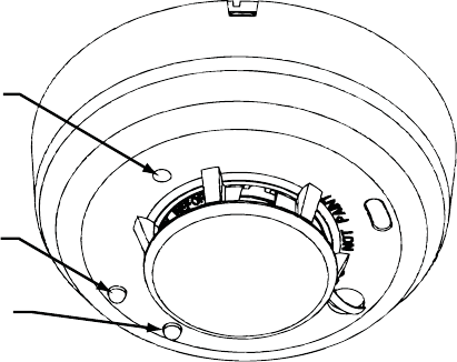
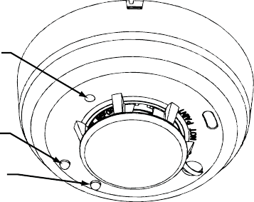
Two LEDs and a sounder on the detector provide local visual and audi-
ble indication of the detector’s status:

Chirp every 45
sec after LED
blinks for 7 days
Temporal
Pattern
Off
Off
Off
Piezoelectric HornGreen LED Red LED
Off
Off
Off
Off
Blinks every 5
sec
Blinks every 5
sec
Blinks every 1
sec
Blinks every 45
sec
Blinks every 5
sec
Blinks every 10
sec
Low Battery
Smoke Alarm
Out of
Sensitivity
Normal
(Standby)
Power-up
Table 1: Detector LED Modes
During initial power-up, the red and green LEDs will blink synchronous-
ly once every 5 seconds. It will take approximately 20 seconds for the
detector to fi nish the power-up cycle (see Table 1).
After the power-up cycle has been completed and the detector is
functioning normally within its listed sensitivity range, the green LED
blinks once every 10 seconds. If the detector is in need of maintenance
because its sensitivity has shifted outside the listed limits, the red LED
blinks once every 5 seconds. When the alarm has been activated by
smoke, the red LED blinks every 1 second. The LED indication must
not be used in place of the tests specifi ed under Testing. If the detector
senses a low battery condition, the red LED blinks once every 45 sec-
onds.
Low Battery Detection:
The Model SD4-MC(US) is powered by a single 3-volt CR123A Lithium
battery. The detector checks for a low battery at least every 65 minutes.
In addition, the red LED of the Model SD4-MC(US) will blink every 45
seconds and the test switch will be disabled. This condition will exist for
a minimum of 7 days, and then the detector’s horn will “chirp” about
every 45 seconds. Pressing the test switch during this time will silence
the chirps for 12 hours. The battery should be replaced BEFORE the
chirps begin. Be sure to replace the battery with a fresh one. Batteries
can be purchased directly from Silent Call Communications by calling
1-800-572-5227, or online at www.silentcall.com.
Battery Life Expectancy:
Replace the battery once a year or immediately when the low battery
indicator starts to blink and the horn begins to chirp.
Battery Installation and Replacement:
To replace the battery:
1. Remove the detector from its mounting base by twisting the detec-
tor counterclockwise. Remove the battery and dispose of it
properly.
2. To ensure proper power-down sequence, wait a minimum of 20
seconds before installing new battery.
3. Install a new approved 3-volt Lithium battery in the battery com-
partment. Follow the polarity diagram inside the compartment.
4. Reinstall the smoke detector onto the mounting base by turning
the detector clockwise.
5. The green LED should blink about once every 10 seconds to indicate
normal operation. If the battery is not installed correctly, the smoke
detector will not operate and the battery may be damaged. If the
detector does not appear to be sending a signal during any of the
tests, check for correct battery installation and for a fully charged
battery.
6. Test Smoke detector operation with Medallion Series Receiver to
verify proper operation.
NFPA Required Protection:
This smoke detector should be installed in accordance with the Nation-
al Fire Protection Association, Standard 72 (National Fire Protection
Association, Quincy, MA 002269). This detector will provide maximum
protection when installed in compliance with the National Fire Protec-
tion Association (NFPA). Standard NFPA 72, household fi re warning
equipment
“For your Information, the National Fire Alarm and Signaling Code
NFPA reads as follows”
11.5.1* Required Detection
Where required by applicable laws, codes, or standards for a specifi c
type of occupancy, approved single and multiple-station smoke alarms
shall be installed as follows:
1. *In all Sleeping Rooms and Quest Rooms.
2. *Outside of each separate dwelling unit sleeping area, within 6.4 m
(21 ft) of any door to a sleeping room, with the distance measured
along a path of travel.
3. On every level of a dwelling unit, including basements.
4. On every level of a residential board and care occupancy(small fa-
cility), including basements and excluding crawl spaces and unfi n-
ished attics.
5. *In living area(s) of a guest suite.
6. In the living area(s) of a residential board and care occupancy (small
facility).
(Reprinted with permission from NFPA 72®, National Fire Alarm Code
Copyright© 2007 National Fire Protection Association, Quincy MA
02269. This reprinted material is not the complete and offi cial position
of the Nation Fire Protection Association, on the referenced subject
which is represented only by the standard in its entirety.)
(National Fire Alarm Code® and NFPA 72® are registered trademarks of
the National Fire Protection Association, Inc., Quincy, MA 02269.)
Recommended Locations for Smoke Detectors:
The National Fire Protection Agency (NFPA) recommends one smoke
detector on every fl oor, in every sleeping area, and in every bedroom. In
new construction, the smoke detectors must be AC powered and inter-
connected. For additional coverage, it is recommended that you install
a smoke detector in all rooms, halls, storage areas, fi nished attics, and
basements where temperatures normally remain between 4.4°C to
37.8°C. Make sure no door or other obstruction could keep smoke from
reaching detectors.
Specifically locate detectors:
• On every level of your residence, including basements and fi nished
attics.
• Inside every Bedroom, especially if people sleep with the doors
closed.
• Inside every bedroom where electrical appliances (such as portable
heaters or humidifi ers) are operated where someone sleeps.
• At the bottom of the basement stairwell.
• At the top of the fi rst-to-second fl oor stairwell, as long as no other
door or other obstructions block the path of smoke to the detector
• As close to the center of the ceiling as possible. If this is not practi-
cal, put the detector on the ceiling, but no closer than 4 inches (10
cm) from any wall or corner. See fi gure 1.
• If wall mounting is permitted by your local and state codes. Put the
top of wall-mounted detectors between 4 and 6 inches (10 and 15
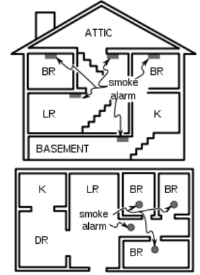
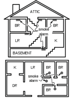
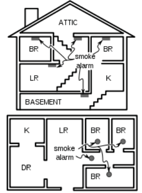
PLACE ONE SMOKE ALARM ON EVERY FLOOR AND SLEEP ROOM
Figure 1: Recommended locations for
smoke alarms
MULTI-STORY
SINGLE LEVEL
cm) from the ceiling. see fi gure 1.
• Put a smoke detector at both ends of a bedroom hallway if the hall-
way is more than 40 feet (12 meters) long.
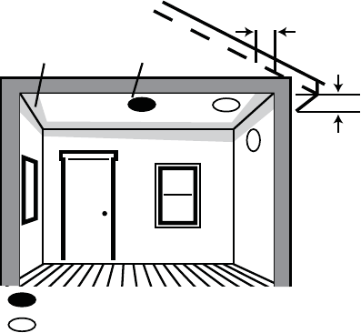
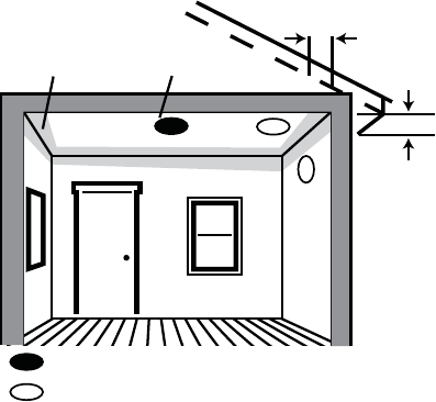
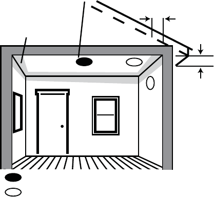
Best location
Acceptable location
Dead
Air
Space
Best in
center of
ceiling
No closer than 4 inch
(10 cm) from side wall
Mount on wall at least 4 inch
(10 cm) from ceiling
No more than 6 inches
(15 cm) from ceiling
Figure 1.2: Recommended smoke detector mounting locations.
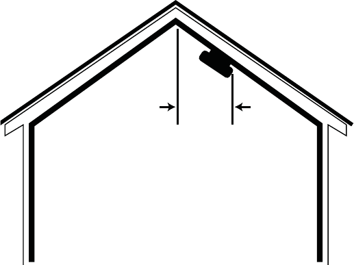
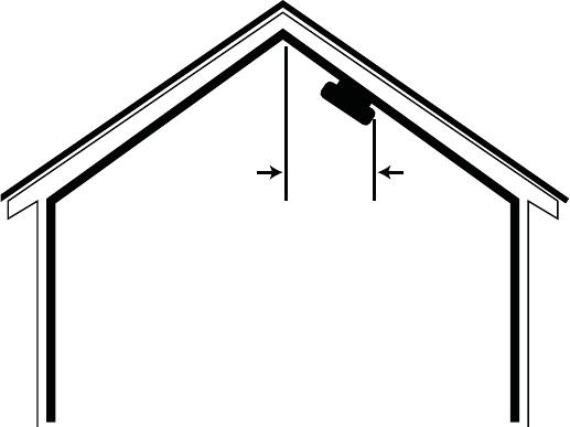
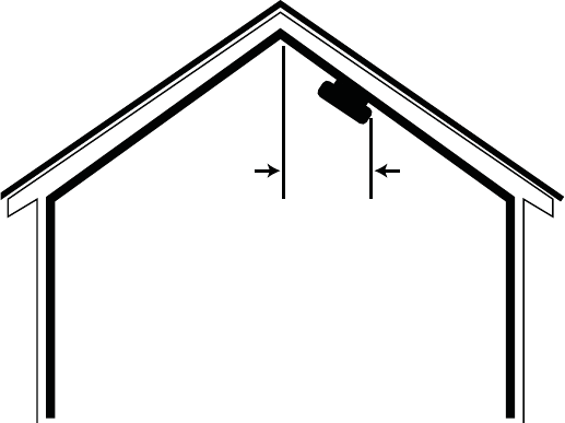
• In rooms with sloped, peaked, or gabled ceilings, mount detectors
within 3 feet (0.9 meters) measured horizontally from the highest
point of the ceiling. See fi gure 2.
Horizontal
distance
from peak
3 feet
(0.9 m)
Figure 2: Recommended smoke detector location in rooms with sloped,
gabled, or peaked ceilings.
Where Smoke Detectors Should Not Be Located:
Nuisance alarms are caused by placing detectors where they will not
operate properly. To avoid nuisance alarms, do not place detectors:
• In or near areas where combustion particles are normally present
such as kitchens, in garages where there are particles of combus-
tion from vehicle exhausts, near furnaces, hot water heaters, or gas
space heaters. Install detectors at least 20 feet (6 meters) away from
kitchens and any other areas where combustion particles are nor-
mally present.
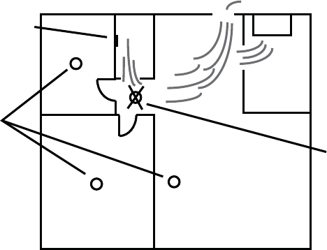
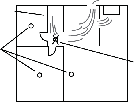
• In air streams passing by kitchens. Figure 3 shows how a detector
can be exposed to combustion particles in normal air movement
paths, and how to correct this situation.
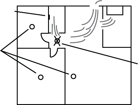
Air Return
Bedroom
Bath
Air Flow
Stove
Kitchen
Correct
Bedroom Living Room
Incorrect
Figure 3: Recommended smoke detector locations to avoid air streams
with combustion particles.
• In damp or very humid areas, or next to bathrooms with showers.
The moisture in humid air can enter the sensing chamber as water
vapor, and will cool and condense into droplets that cause a nui-
sance alarm. Install detectors at least 5 feet (1.5 meters) away from
bathrooms.
• In very dusty or dirty areas. Dust and dirt can build up on the de-
tector sensing chamber and make it overly sensitive, or can block
openings to the sensing chamber and keep the detector from sens-
ing smoke.
• Near fresh air inlets or returns or excessively drafty areas. Air
conditioners, heaters, fans, and fresh air intakes and returns can
drive smoke away from smoke detectors, making the detectors less
effective.
• In dead air spaces at the top of a peaked roof or in the corners be-
tween ceilings and walls. Dead air may prevent smoke from reach-
ing the detector. See fi gures 4 and 5 for recommended mounting
location.
• In insect-infested areas. If insects enter a detector’s sensing cham-
ber they may cause a nuisance alarm. Get rid of the bugs before
installing detectors where bugs are a problem.
• Near fl orescent light fi xtures. Electrical “noise” from nearby fl ores-
cent light fi xtures may cause a nuisance alarm. Install detectors at
least 10 feet (3 meters) away from such light fi xtures.
Limitations of Smoke Alarms
• Smoke detectors will not work without power. Battery operated
detectors will not work without batteries, with dead batteries, or
if the batteries are not put in properly. AC-powered detectors will
not work if their AC power supply is cut off by an electrical fi re,
and open fuse or circuit breaker, or for any other reason. If you are
concerned about the reliability of either batteries or your AC power
supply for any of the above reasons, you should install both battery
powered and AC powered detectors for maximum safety.
• Smoke detectors must be tested regularly to make sure the batteries
and the alarm circuits are in good operating condition.
• Smoke detectors may not sense fi res that start where smoke cannot
reach the detectors such as in chimneys, in walls, on roofs, or on the
other side of closed doors. If bedroom doors are usually closed at
night, detectors should be placed in each bedroom as well as in the
common hallway between them.
• Smoke detectors also may not sense a fi re on another level of the
residence or building. For example, a second-fl oor detector may not
sense a fi rst-fl oor or basement fi re. Therefore, detectors should be
placed on every level of a residence or building.
• The horn in your detector meets or exceeds current audibility
requirements of Underwriters Laboratories. However, if the detec-
tor is located outside a bedroom, it may not wake a sound sleeper,
especially if the bedroom door is closed or only partly open. If the
detector is located on a different level of the residence than the
bedrooms, it is even less likely to wake up people sleeping in the
bedrooms.
• All types of smoke detectors have limitations. No type of smoke
detector can sense every kind of fi re every time. In general, detec-
tors may not always warn you about fi red caused by carelessness
and safety hazards like smoking in bed, violent explosions, escaping
gas, improper storage of fl ammable materials, overloaded electrical
circuits, children playing with matches or arson.
• Installing smoke detectors may make you eligible for lower insur-
ance rates, but smoke detectors are not a substitute for insurance.
Homeowners and renters should continue to insure their lives and
property.
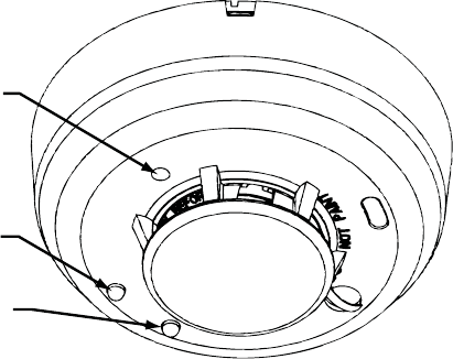
Test Switch
Green LED
Red LED
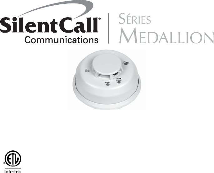
Figure 4: Silent Call Model #SD4-MC(US) Wireless Smoke Detector
Programming
The smoke detector is pre-programmed at the factory.
Transmitter Setting
The Silent Call® system is digitally coded. The Medallion Series SD4-
MC(US) Smoke Detector is set to a unique million code setting at the
factory and therefore never requires the need of a different code.
Transmitter operates at a frequency of 418MHz.
Mounting
First, determine the best location for the smoke detector, one that pro-
vides a strong wireless transmission path and proper smoke detection.
A GOOD TRANSMISSION PATH MUST BE ESTABLISHED FROM THE
PROPOSED MOUNTING LOCATION BEFORE PERMANENTLY INSTALL-
ING THE DETECTOR. To check, perform the test described in the TEST-
ING SIGNAL STRENGTH section of this manual. To mount the detector,
perform the following steps:
1. Once a suitable location has been determined, install the mounting
base on the ceiling or on the wall (if local ordinances permit). Use
the two screws and anchors provided.
2. Turn the detector in a clockwise direction in the mounting base until
it clicks into place.
3. Test the detector immediately after completing the installation as
described in the TESTING section of this manual.
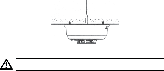
Figure 5: Mount Detector Across Ceiling Panel Support.
DO NOT attach the detector to removable ceiling panels.
Attach the detector across panel support as shown in Figure 5.
Dust Covers are an effective way to limit the entry of dust into the
smoke detector sensing chamber during construction. However, they
may not completely prevent airborne dust particles from entering the
detector. Therefore, it is recommended that the detectors be removed
before beginning construction or other dust producing activity. When
returning the system to service, be sure to remove the dust covers from
any detectors that were left in place during construction.
Smoke detectors are not to be used with detector guards unless the
combination has been evaluated and found suitable for that purpose.
Testing the Sensor
Detectors must be tested after installation and following periodic main-
tenance. The Model #SD4-MC(US) may be tested as follows:
A. Test Switch
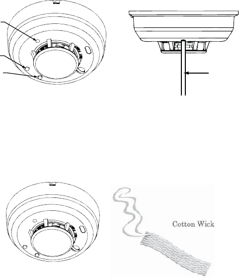
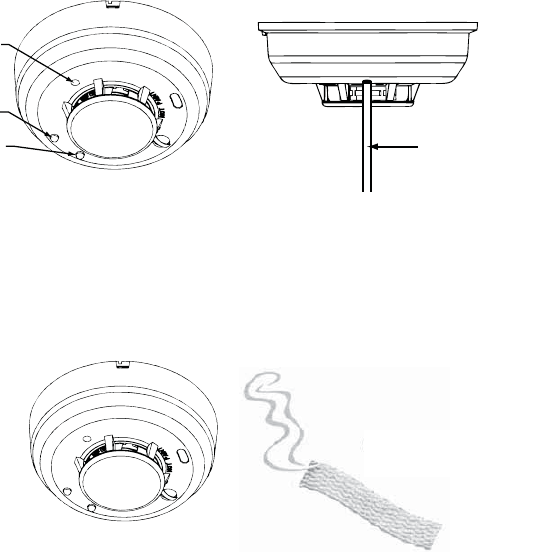
1. A recessed test switch is located on the detector housing
(see Figure 6).
2. Push and hold the recessed test switch for a minimum of 5 seconds.
Use a small screwdriver or Allen key with maximum diameter of
0.18 inch (the detector will trigger and then the smoke detector will
go into alarm thus sending a transmitting signal to the receiver. If
the tool is removed from the recessed switch the sounder will shut
off)
If the detector is within the listed sensitivity limits, the LED on the
detector should blink once per second and the horn should sound with-
in 3 seconds.
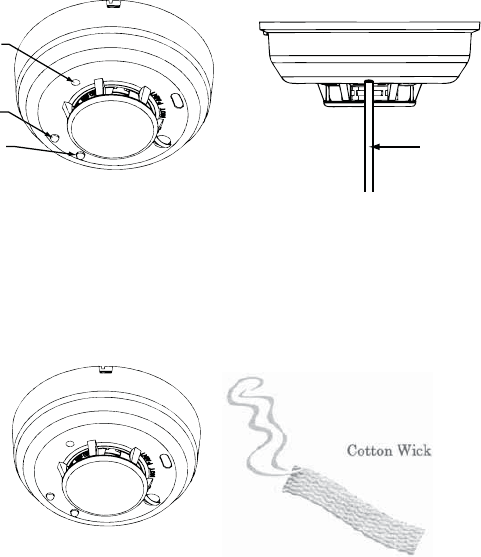
Test Switch
Green LED
Red LED PUSH RECESSED
SWITCH WITH A
0.18’ MAX
DIAMETER TOOL
Figure 6: Recessed Test Switch Opening
B. Smoke Entry Test
Hold a smoldering punk stick or cotton wick at the side of the detec-
tor and gently blow smoke through the detector until the unit alarms.
Canned aerosol is also an accepted method.
Figure 7: Testing with Wick
Testing Signal Strength
A test should be performed before installation to determine a strong
communication path with the receiver and after installation is complete.
Also the owner/user should test the unit at least weekly.
Testing Programming
A test should be performed before installation to ensure the detector
transmitter address is properly programmed to the receiver, and are
operational as a system.
Maintenance
NOTE: Power must be removed from the detector before performing
maintenance of any kind by removing the detector’s battery.
1. To ensure proper power-down sequence, battery must be removed
from detector for a minimum of 20 seconds before servicing.
2. Vacuum the cover or use canned air to remove any dust or debris.
3. Using a vacuum or canned air spray carefully clean any dust or de-
bris From Smoke Detector Cover.
4. Reinstall the detector and test. (see the Testing section).
What to do in case of fire
• Don’t panic; stay calm. Follow your family escape plan.
• Get of the house as quickly as possible. Don’t stop to get dressed or
collect anything.
• Feel doors with the back of your hand prior to opening them. If a
door is cool, open it slowly. Don’t open a hot door. Keep door and
windows closed, unless you must escape through them.
• Cover your nose and mouth with a cloth (preferably damp). Take
short shallow breaths.
• Meet at the planned meeting place outside your home, and take a
head count to make sure everybody got out safely.
• Call the fi re department from outside. Give your address, then your
name.
• Never go back inside a burning building for any reason.
• Contact your fi re department for suggestions and ideas on how to
make your home safer.
FCC INFORMATION NOTICE:
Unauthorized changes or modifi cations could void the user’s authority
to operate the equipment.
This device complies with Part 15 of the FCC Rules. Operation is subject
to the following two conditions: (1) This device may not cause harmful
interference, and (2) this device must accept any interference received,
including interference that may cause undesired operation of the device.
This equipment has been tested and found to comply with the limits
for a Class B digital device, pursuant to Part 15 of FCC Rules. These
limits are designed to provide reasonable protection against harmful
interference in a residential installation. This equipment generates, uses
and can radiate radio frequency energy and if not installed and used
in accordance with the instructions, may cause harmful interference to
radio communications. However, there is no guarantee that interference
will not occur in a particular installation. If this equipment does cause
harmful interference to radio or television reception, which can be de-
termined by turning the equipment off and on, the user is encouraged
to try to correct the interference by one or more of the following mea-
sures:
• Reorient or relocate the receiving antenna.
• Increase the separation between the equipment and the receiver
• Connect the equipment into an outlet on a circuit different from that
to which the receiver is connected.
• Consult the dealer or an experienced radio/television technician for
help

Specifications
Power Source:
Height:
Diameter:
Weight:
Operating Ambient Temperature Range:
Operating Humidity Range:
Agency Listings:
One 3-volt CR123A Lithium Battery (included).
(Replace with Panasonic CR123A or DURACELL
DL123A)
These batteries are available at local retail stores.
You can also order Replacement Batteries Online
at www.Silentcall.com.
2.3 inches (58 mm)
5.3 inches (135 mm) (with mounting base)
8.5 oz. (241 g) (without battery)
40° to 100°F (4.4° to 37.8°C)
0% to 95% Relative Humidity
Conforms to UL STD 217
For Warranty Claims/Repairs Please Contact the Manufacturer:
Silent Call Communications
5095 Williams Lake Road
Waterford, MI 48329
800-572-5227
Please Visit www.Silentcall.com
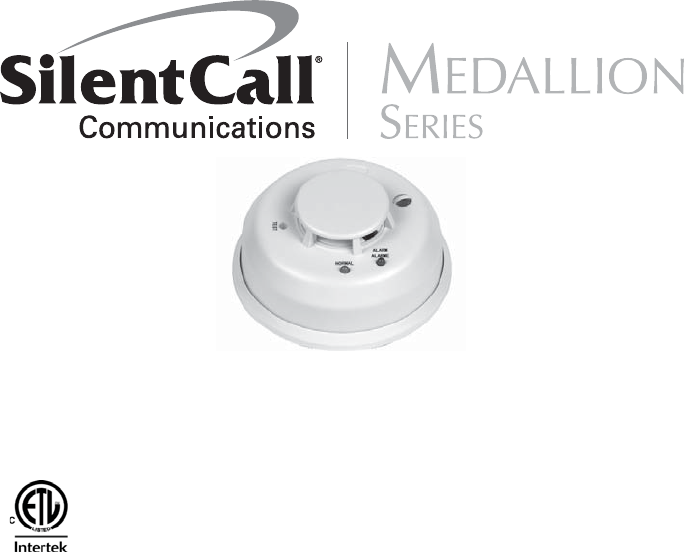
PHOTOELECTRONIC SMOKE DETECTOR
WITH BUILT-IN WIRELESS TRANSMITTER
Installation and Operation Manual
Model # SD4-MC
418 MHZ TRANSMITTER
Document #
1081253126052
General Information
Before installing detectors, please thoroughly read these installation
instructions. For detailed information on detector spacing, placement,
zoning, wiring, and special applications refer to local building codes that
may apply.
NOTICE: Do not discard this manual. Manual should be left with the
owner/user of this equipment.
IMPORTANT: This detector must be tested and maintained regularly.
Test detector operation weekly. The detector should be cleaned at least
once a year.
NOTE: Smoke Detectors have a limited life. Smoke detectors should
be replaced immediately if not operating properly. You should always
replace a smoke detector after 10 years from date of purchase.
NOTE: Remove battery tab before installation.
NOTE: Radio Frequency device operates at 418MHz
IC: 4498A-SD4418SC
General Description:
The Model SD4-MC photocell electronic smoke detector with built-
in wireless transmitter is intended for use with the Silent Call® Mini
receiver to form an alerting system. The transmitter will send alarm
condition messages to the system’s receiver.
The SD4-MC wireless transmitter operation is to be used only with
Silent Call® Medallion Series Receivers. The transmitted signal incor-
porates a Million Code Address principle that provides each SD4-MC
detector with a unique one in a million address. This helps to keep
any cross talk between like transmitters in a typical single living,
multi-dwelling, or apartment building to a minimum where it is possible
to have adjacent apartments with Medallion Series Receivers.
IMPORTANT: The range and proper operation of any wireless device
will vary depending on its surroundings. It is very important that each
SD4-MC detector is tested with each receiver intended for Alarm.
The Model SD4-MC incorporates a state of the art optical sensing cham-
ber and an advanced microprocessor. The microprocessor allows the
detector to automatically maintain proper operation at factory calibrated
detection levels, even when sensitivity is altered due to the presence
of contaminants settling into the unit’s smoke chamber. In order for
this feature to work properly, the chamber must never be opened while
power is applied to the smoke detector.
This includes cleaning, maintenance or screen replacement.
The Model SD4-MC contains a piezoelectric horn which generates the
ANSI S3.41 temporal pattern in an alarm condition. During an alarm
condition, pressing the detector’s test switch will silence the piezo-
electric horn for 5 minutes. The built-in Drift Compensation algorithm
automatically maintains the sensitivity of the detector. The mounting
base installation is simplifi ed by the incorporation of features compat-
ible with drywall fasteners or other methods that provide a method for
securing the detector in place.
Current studies have shown smoke detectors may not awaken all
sleeping individuals, and that it is the responsibility of individuals in the
household that are capable of assisting others to provide assistance to
those who may not be awakened by the alarm sound, or those who may
be incapable of safely evacuating the area unassisted.
Two LEDs and a sounder on the detector provide local visual and audi-
ble indication of the detector’s status:

Chirp every 45
sec after LED
blinks for 7 days
Temporal
Pattern
Off
Off
Off
Piezoelectric HornGreen LED Red LED
Off
Off
Off
Off
Blinks every 5
sec
Blinks every 5
sec
Blinks every 1
sec
Blinks every 45
sec
Blinks every 5
sec
Blinks every 10
sec
Low Battery
Smoke Alarm
Out of
Sensitivity
Normal
(Standby)
Power-up
Table 1: Detector LED Modes
During initial power-up, the red and green LEDs will blink synchronous-
ly once every 5 seconds. It will take approximately 20 seconds for the
detector to fi nish the power-up cycle (see Table 1).
After the power-up cycle has been completed and the detector is
functioning normally within its listed sensitivity range, the green LED
blinks once every 10 seconds. If the detector is in need of maintenance
because its sensitivity has shifted outside the listed limits, the red LED
blinks once every 5 seconds. When the alarm has been activated by
smoke, the red LED blinks every 1 second. The LED indication must
not be used in place of the tests specifi ed under Testing. If the detector
senses a low battery condition, the red LED blinks once every 45 sec-
onds.
Low Battery Detection:
The Model SD4-MC is powered by a single 3-volt CR123A Lithium bat-
tery. The detector checks for a low battery at least every 65 minutes. In
addition, the red LED of the Model SD4-MC will blink every 45 seconds
and the test switch will be disabled. This condition will exist for a mini-
mum of 7 days, and then the detector’s horn will “chirp” about every 45
seconds. Pressing the test switch during this time will silence the chirps
for 12 hours. The battery should be replaced BEFORE the chirps begin.
Be sure to replace the battery with a fresh one. Batteries can be pur-
chased directly from Silent Call Communications by calling
1-800-572-5227, or online at www.silentcall.com.
Battery Life Expectancy:
Replace the battery once a year or immediately when the low battery
indicator starts to blink and the horn begins to chirp.
Battery Installation and Replacement:
To replace the battery:
1. Remove the detector from its mounting base by twisting the de
tector counterclockwise. Remove the battery and dispose of it
properly.
2. To ensure proper power-down sequence, wait a minimum of 20
seconds before installing new battery.
3. Install a new approved 3-volt Lithium battery in the battery com
partment. Follow the polarity diagram inside the compartment.
4. Reinstall the smoke detector onto the mounting base by turning
the detector clockwise.
5. The green LED should blink about once every 10 seconds to indicate
normal operation. If the battery is not installed correctly, the smoke
detector will not operate and the battery may be damaged. If the
detector does not appear to be sending a signal during any of the
tests, check for correct battery installation and for a fully charged
battery.
6. Test Smoke detector operation with Medallion Series Receiver to
verify proper operation.
Recommended Locations for Smoke Detectors:
One smoke detector on every fl oor, in every sleeping area, and in every
bedroom. In new construction, the smoke detectors must be AC pow-
ered and interconnected. For additional coverage, it is recommended
that you install a smoke detector in all rooms, halls, storage areas,
fi nished attics, and basements where temperatures normally remain
between 4.4°C to 37.8°C. Make sure no door or other obstruction could
keep smoke from reaching detectors.
Speci cally locate detectors:
• On every level of your residence, including basements and fi nished
attics.
• Inside every Bedroom, especially if people sleep with the doors
closed.
• Inside every bedroom where electrical appliances (such as portable
heaters or humidifi ers) are operated where someone sleeps.
• At the bottom of the basement stairwell.
• At the top of the fi rst-to-second fl oor stairwell, as long as no other
door or other obstructions block the path of smoke to the detector
• As close to the center of the ceiling as possible. If this is not practi-
cal, put the detector on the ceiling, but no closer than 4 inches (10
cm) from any wall or corner. See fi gure 1.
• If wall mounting is permitted by your local and state codes. Put the
PLACE ONE SMOKE ALARM ON EVERY FLOOR AND SLEEP ROOM
Figure 1: Recommended locations for
smoke alarms
MULTI-STORY
SINGLE LEVEL
top of wall-mounted detectors between 4 and 6 inches (10 and 15
cm) from the ceiling. see fi gure 1.
• Put a smoke detector at both ends of a bedroom hallway if the hall-
way is more than 40 feet (12 meters) long.
Best location
Acceptable location
Dead
Air
Space
Best in
center of
ceiling
No closer than 4 inch
(10 cm) from side wall
Mount on wall at least 4 inch
(10 cm) from ceiling
No more than 6 inches
(15 cm) from ceiling
Figure 1.2: Recommended smoke detector mounting locations.
• In rooms with sloped, peaked, or gabled ceilings, mount detectors
within 3 feet (0.9 meters) measured horizontally from the highest
point of the ceiling. See fi gure 2.
Horizontal
distance
from peak
3 feet
(0.9 m)
Figure 2: Recommended smoke detector location in rooms with sloped,
gabled, or peaked ceilings.
Where Smoke Detectors Should Not Be Located:
Nuisance alarms are caused by placing detectors where they will not
operate properly. To avoid nuisance alarms, do not place detectors:
• In or near areas where combustion particles are normally present
such as kitchens, in garages where there are particles of combus-
tion from vehicle exhausts, near furnaces, hot water heaters, or gas
space heaters. Install detectors at least 20 feet (6 meters) away from
kitchens and any other areas where combustion particles are nor-
mally present.
• In air streams passing by kitchens. Figure 3 shows how a detector
can be exposed to combustion particles in normal air movement
paths, and how to correct this situation.
Air Return
Bedroom
Bath
Air Flow
Stove
Kitchen
Correct
Bedroom Living Room
Incorrect
Figure 3: recommended smoke detector locations to avoid air streams
with combustion particles.
• In damp or very humid areas, or next to bathrooms with showers.
The moisture in humid air can enter the sensing chamber as water
vapor, and will cool and condense into droplets that cause a nui-
sance alarm. Install detectors at least 5 feet (1.5 meters) away from
bathrooms.
• In very dusty or dirty areas. Dust and dirt can build up on the de-
tector sensing chamber and make it overly sensitive, or can block
openings to the sensing chamber and keep the detector from sens-
ing smoke.
• Near fresh air inlets or returns or excessively drafty areas. Air
conditioners, heaters, fans, and fresh air intakes and returns can
drive smoke away from smoke detectors, making the detectors less
effective.
• In dead air spaces at the top of a peaked roof or in the corners be-
tween ceilings and walls. Dead air may prevent smoke from reach-
ing the detector. See fi gures 4 and 5 for recommended mounting
location.
• In insect-infested areas. If insects enter a detector’s sensing cham-
ber they may cause a nuisance alarm. Get rid of the bugs before
installing detectors where bugs are a problem.
• Near fl orescent light fi xtures. Electrical “noise” from nearby fl ores-
cent light fi xtures may cause a nuisance alarm. Install detectors at
least 10 feet (3 meters) away from such light fi xtures.
Limitations of Smoke Alarms
• Smoke detectors will not work without power. Battery operated
detectors will not work without batteries, with dead batteries, or
if the batteries are not put in properly. AC-powered detectors will
not work if their AC power supply is cut off by an electrical fi re,
and open fuse or circuit breaker, or for any other reason. If you are
concerned about the reliability of either batteries or your AC power
supply for any of the above reasons, you should install both battery
powered and AC powered detectors for maximum safety.
• Smoke detectors must be tested regularly to make sure the batteries
and the alarm circuits are in good operating condition.
• Smoke detectors may not sense fi res that start where smoke cannot
reach the detectors such as in chimneys, in walls, on roofs, or on the
other side of closed doors. If bedroom doors are usually closed at
night, detectors should be placed in each bedroom as well as in the
common hallway between them.
• Smoke detectors also may not sense a fi re on another level of the
residence or building. For example, a second-fl oor detector may not
sense a fi rst-fl oor or basement fi re. Therefore, detectors should be
placed on every level of a residence or building.
• The horn in your detector meets or exceeds current audibility
requirements of Underwriters Laboratories. However, if the detec-
tor is located outside a bedroom, it may not wake a sound sleeper,
especially if the bedroom door is closed or only partly open. If the
detector is located on a different level of the residence than the
bedrooms, it is even less likely to wake up people sleeping in the
bedrooms.
• All types of smoke detectors have limitations. No type of smoke
detector can sense every kind of fi re every time. In general, detec-
tors may not always warn you about fi red caused by carelessness
and safety hazards like smoking in bed, violent explosions, escaping
gas, improper storage of fl ammable materials, overloaded electrical
circuits, children playing with matches or arson.
• Installing smoke detectors may make you eligible for lower insur-
ance rates, but smoke detectors are not a substitute for insurance.
Homeowners and renters should continue to insure their lives and
property.
Test Switch
Green LED
Red LED
Figure 4: Silent Call Model #SD4-MC Wireless Smoke Detector
Programming
The smoke detector is pre-programmed at the factory.
Transmitter Setting
The Silent Call® system is digitally coded. The Medallion Series SD4-
MC Smoke Detector is set to a unique million code setting at the factory
and therefore never requires the need of a different code.
Transmitter operates at a frequency of 418MHz.
Mounting
First, determine the best location for the smoke detector, one that pro-
vides a strong wireless transmission path and proper smoke detection.
A GOOD TRANSMISSION PATH MUST BE ESTABLISHED FROM THE
PROPOSED MOUNTING LOCATION BEFORE PERMANENTLY INSTALL-
ING THE DETECTOR. To check, perform the test described in the TEST-
ING SIGNAL STRENGTH section of this manual. To mount the detector,
perform the following steps:
1. Once a suitable location has been determined, install the mounting
base on the ceiling or on the wall (if local ordinances permit). Use
the two screws and anchors provided.
2. Turn the detector in a clockwise direction in the mounting base until
it clicks into place.
3. Test the detector immediately after completing the installation as
described in the TESTING section of this manual.
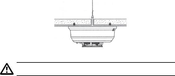
Figure 5: Mount Detector Across Ceiling Panel Support.
DO NOT attach the detector to removable ceiling panels.
Attach the detector across panel support as shown in Figure 5.
Dust Covers are an effective way to limit the entry of dust into the
smoke detector sensing chamber during construction. However, they
may not completely prevent airborne dust particles from entering the
detector. Therefore, it is recommended that the detectors be removed
before beginning construction or other dust producing activity. When
returning the system to service, be sure to remove the dust covers from
any detectors that were left in place during construction.
Smoke detectors are not to be used with detector guards unless the
combination has been evaluated and found suitable for that purpose.
Testing the Sensor
Detectors must be tested after installation and following periodic main-
tenance. The Model #SD4-MC may be tested as follows:
A. Test Switch
1. A recessed test switch is located on the detector housing
(see Figure 6).
2. Push and hold the recessed test switch for a minimum of 5 seconds.
Use a small screwdriver or Allen key with maximum diameter of
0.18 inch (the detector will trigger and then the smoke detector will
go into alarm thus sending a transmitting signal to the receiver. If
the tool is removed from the recessed switch the sounder will shut
off)
If the detector is within the listed sensitivity limits, the LED on the
detector should blink once per second and the horn should sound with-
in 3 seconds.
Test Switch
Green LED
Red LED PUSH RECESSED
SWITCH WITH A
0.18’ MAX
DIAMETER TOOL
Figure 6: Recessed Test Switch Opening
B. Smoke Entry Test
Hold a smoldering punk stick or cotton wick at the side of the detec-
tor and gently blow smoke through the detector until the unit alarms.
Canned aerosol is also an accepted method.
Figure 7: Testing with Wick
Testing Signal Strength
A test should be performed before installation to determine a strong
communication path with the receiver and after installation is complete.
Also the owner/user should test the unit at least weekly.
Testing Programming
A test should be performed before installation to ensure the detector
transmitter address is properly programmed to the receiver, and are
operational as a system.
Maintenance
NOTE: Power must be removed from the detector before performing
maintenance of any kind by removing the detector’s battery.
1. To ensure proper power-down sequence, battery must be removed
from detector for a minimum of 20 seconds before servicing.
2. Vacuum the cover or use canned air to remove any dust or debris.
3. Using a vacuum or canned air spray carefully clean any dust or de-
bris From Smoke Detector Cover.
4. Reinstall the detector and test. (see the Testing section).
What to do in case of re
• Don’t panic; stay calm. Follow your family escape plan.
• Get of the house as quickly as possible. Don’t stop to get dressed or
collect anything.
• Feel doors with the back of your hand prior to opening them. If a
door is cool, open it slowly. Don’t open a hot door. Keep door and
windows closed, unless you must escape through them.
• Cover your nose and mouth with a cloth (preferably damp). Take
short shallow breaths.
• Meet at the planned meeting place outside your home, and take a
head count to make sure everybody got out safely.
• Call the fi re department from outside. Give your address, then your
name.
• Never go back inside a burning building for any reason.
• Contact your fi re department for suggestions and ideas on how to
make your home safer.
IC INFORMATION NOTICE:
Unauthorized changes or modi cations could void the user’s authority
to operate the equipment.
This device complies with Industry Canada license-exempt RSS
standard(s).
Operation is subject to the following two conditions: (1) This device
may not cause harmful interference, and (2) this device must accept any
interference received, including interference that may cause undesired
operation of the device. This equipment has been tested and found to
comply with the limits for a Class B digital device, pursuant to Part 15 of
FCC Rules. These limits are designed to provide reasonable protection
against harmful interference in a residential installation. This equipment
generates, uses and can radiate radio frequency energy and if not in-
stalled and used in accordance with the instructions, may cause harmful
interference to radio communications. However, there is no guarantee
that interference will not occur in a particular installation. If this equip-
ment does cause harmful interference to radio or television reception,
which can be determined by turning the equipment off and on, the user
is encouraged to try to correct the interference by one or more of the
following measures:
• Reorient or relocate the receiving antenna.
• Increase the separation between the equipment and the receiver
• Connect the equipment into an outlet on a circuit different from that
• to which the receiver is connected.
• Consult the dealer or an experienced radio/television technician for
help

Speci cations
Power Source:
Height:
Diameter:
Weight:
Operating Ambient Temperature Range:
Operating Humidity Range:
Agency Listings:
One 3-volt CR123A Lithium Battery (included).
(Replace with Panasonic CR123A or DURACELL
DL123A)
These batteries are available at many local retail
stores.
You can also order Replacement Batteries Online
at www.Silentcall.com.
2.3 inches (58 mm)
5.3 inches (135 mm) (with mounting base)
8.5 oz. (241 g) (without battery)
40° to 100°F (4.4° to 37.8°C)
0% to 95% Relative Humidity
Tested to comply with CAN/ULC-S531-02
For Warranty Claims/Repairs Please Contact the Manufacturer:
Silent Call Communications
5095 Williams Lake Road
Waterford, MI 48329
800-572-5227
Please Visit www.Silentcall.com
DÉTECTEUR DE FUMÉE PHOTO ÉLECTRONIQUE
AVEC TRANSMETTEUR SANS FIL INCORPORÉ
INSTRUCTIONS D’INSTALLATION ET D’EMPLOI
Modèle # SD4-MC
TRANSMETTEUR 418 MHZ
Document #
108125
3126052
Informations générales
Avant l’installation de détecteurs, veuillez lire attentivement ces instructions
d’installation. Pour des informations détaillées sur l’espacement des détec-
teurs, leur position, leur câblage et leurs applications spéciales, veuillez vous
reporter aux codes du bâtiment locaux.
REMARQUE: Ne jetez pas ce manuel. Ce manuel doit demeurer en la posses-
sion du propriétaire / de l’utilisateur de l’équipement.
IMPORTANT: Ce détecteur doit être testé et entretenu. Testez toutes les
semaines le fonctionnement du détecteur. Le détecteur doit être nettoyé au
moins une fois par an.
REMARQUE: Les détecteurs de fumée ont une durée de vie limitée. Les détec-
teurs de fumée doivent être remplacés immédiatement s’ils ne fonctionnent
pas correctement. Un détecteur de fumée doit toujours être remplacé après
10 ans à compter de la date d’achat.
REMARQUE: Retirez l’onglet de la pile avant l’installation.
REMARQUE: La radiofréquence de l’appareil est 418 MHz
IC: 4498A-SD4418SC
Description générale:
Le Modèle SD4-MC de détecteur de fumée électronique à cellule photoélec-
trique avec transmetteur sans fi l incorporé doit être utilisé avec le Mini récep-
teur Silent Call® pour constituer un système d’alerte. Le transmetteur émettra
des messages de situation d’alarme en direction du récepteur du système.
Le transmetteur sans fi l SD4-MC ne doit être utilisé qu’avec des récepteurs
Silent Call® de la série Medallion. Le signal transmis repose sur le principe
de Million Code Address qui attribue à chaque détecteur SD4-MC une adres-
se unique parmi un million. Ceci permet de limiter au minimum toute com-
munication croisée entre des transmetteurs semblables dans un logement
individuel, collectif ou un bâtiment d’appartements lorsqu’il est possible que
des récepteurs de la série Medallion se trouvent dans des appartements adja-
cents.
IMPORTANT : La portée et le bon fonctionnement de tout appareil sans fi l
dépendent de son environnement. Il est très important que chaque détecteur
SD4-MC soit testé avec chaque récepteur devant servir d’alarme.
Le Modèle SD4-MC comprend un compartiment de capteur optique ultramod-
erne et un microprocesseur avancé. Le microprocesseur permet de veiller
automatiquement au bon fonctionnement du détecteur à des niveaux de
détection calibrés en usine, même lorsque la sensibilité est limitée en rai-
son de la présence de contaminants s’accumulant dans le compartiment de
captage de la fumée de l’appareil. Pour que cette fonctionnalité soit effi cace,
le compartiment ne doit jamais être ouvert lorsque le détecteur de fumée est
sous tension. C’est le cas lors du nettoyage, de la maintenance ou du rem-
placement du fi ltre.
Le Modèle SD4-MC contient un avertisseur piézoélectrique qui produit la
séquence ANSI S3.41 temporelle en cas d’alarme. Lors d’une alarme, la
pression sur l’interrupteur de test du détecteur rend l’avertisseur piézoélec-
trique silencieux pendant 5 minutes. L’algorithme incorporé de compensation
de dérivation maintient la sensibilité du détecteur. L’installation du support
de montage est simplifi ée par l’incorporation de fonctionnalités compatibles
avec les attaches pour cloison sèches ou autres méthodes permettant d’assu-
jettir les détecteurs en place.
Des études récentes ont montré que les détecteurs de fumée peuvent ne pas
réveiller tout le monde, et qu’il appartient aux habitants de la résidence qui
sont en mesure de le faire d’aider les autres qui sont susceptibles de ne pas
avoir été réveillés par l’alarme sonore, ou ceux qui ne sont pas en mesure
d’évacuer les lieux sans danger sans assistance.
Deux voyants DEL et une sonnerie sur le détecteur fournissent une indication
locale visuelle et audible de l’état du détecteur :

Émet un petit bruit toutes
les 45 secondes lorsque
le voyant DEL a clignoté
pendant 7 jours
Séquence
temporelle
Éteint
Éteint
Éteint
Avertisseur
piézoélectrique
Voyant DEL vert Voyant DEL rouge
Éteint
Éteint
Éteint
Éteint
Clignote toutes
les 5 secondes
Clignote toutes
les 5 secondes
Clignote toutes
les secondes
Clignote toutes
les 45 secondes
Clignote toutes
les 5
Clignote toutes
les 5
Pile presque
épuisée
Alarme de
détection de
fumée
Plus de
sensibilité
Normal
(attente)
Allumage
Tableau 1 : Modes du détecteur DEL
Lors de l’allumage initial, les voyants DEL rouges et verts clignotent de
manière synchronisée une fois toutes les 5 secondes. Il faudra environ 20 sec-
ondes pour que le détecteur achève le cycle d’allumage (voir le Tableau 1).
Lorsqu’il est allumé et que le détecteur fonctionne normalement à l’intérieur
de ses limites de sensibilité, le voyant vert DEL clignote une fois toutes les 10
secondes. Si le détecteur doit faire l’objet d’opérations de maintenance parce
que sa sensibilité s’est déplacée hors des limites indiquées, le voyant rouge
DEL clignote toutes les 5 secondes. Lorsque l’alarme a été activée par la
fumée, le voyant DEL rouge clignote toutes les secondes. L’indicateur DEL ne
doit pas être utilisé au lieu des tests mentionnés dans la rubrique relative aux
tests. Si le détecteur décèle que la pile est presque épuisée, le voyant rouge
DEL clignote une fois toutes les 45 secondes.
Détection de l’épuisement de la pile:
Le Modèle SD4-MC fonctionne grâce à une seule pile au lithium de 3 volts
CR123A. Le détecteur contrôle le niveau de la pile au moins toutes les 65
minutes. Par ailleurs, le voyant rouge DEL du Modèle SD4-MC clignotera
toutes les 45 secondes et l’interrupteur de test sera désactivé. Cette situation
persistera au moins 7 jours, après quoi l’avertisseur du détecteur émettra un
petit bruit toutes les 45 secondes. Si l’on appuie sur le bouton de test pendant
cette période, les petits bruits s’interrompent pendant 12 heures. La batterie
doit être remplacée AVANT que l’appareil commence à émettre les petits
bruits. Veillez à bien remplacer la pile par une pile neuve. Les piles peuvent
être achetées directement auprès de Silent Call Communications en appelant
le 1-800-572-5227, ou en ligne à www.silentcall.com.
Durée d’utilisation de la pile :
Remplacez la pile une fois par an ou dès que l’indicateur d’épuisement de la
pile commence à clignoter et lorsque l’avertisseur commence à émettre un
petit bruit.
Installation et remplacement de la pile :
Pour remplacer la pile:
1. Retirez le détecteur de son support de montage en le faisant tourner dans
le sens contraire des aiguilles d’une montre. Retirez la pile et éliminez-la
comme il convient.
2. Attendez au moins 20 secondes avant d’installer une nouvelle pile pour
veiller à ce que l’appareil soit bien éteint.
3. Installez une pile au lithium de 3 volts neuve dans le compartiment de la
pile. Respectez le diagramme de polarité dans le compartiment.
4. Réinstallez le détecteur de fumée sur le support de montage en faisant
tourner le détecteur dans le sens des aiguilles d’une montre.
5. Le voyant vert DEL doit clignoter environ une fois toutes les 10 secondes
pour indiquer son fonctionnement normal. Si la pile n’est pas installée
correctement, le détecteur de fumée ne fonctionnera pas et la pile peut
être endommagée. Si le détecteur ne semble envoyer de signal pendant
aucun des tests, vérifi ez que la pile est bien installée et que la pile est
totalement chargée.
6. Testez le fonctionnement du détecteur de fumée avec un récepteur la
série Medallion
Emplacements recommandés pour les détecteurs de fumée:
Un détecteur de fumée à chaque étage, dans chaque chambre, et dans chaque
endroit où l’on peut dormir. Dans une construction neuve, les détecteurs de
fumée doivent être alimentés par courant électrique et interconnectés. Pour
bénéfi cier d’une couverture supplémentaire, il est recommandé d’installer un
détecteur de fumée dans toutes les pièces, les corridors, les aires d’entrepos-
age, les greniers aménagés, et les sous-sols lorsque la température y reste en
général entre 4,4°C et 37,8°C. Vérifi ez qu’aucune porte ou autre obstruction ne
peut empêcher la fumée d’atteindre les détecteurs.
Placez spéci quement des détecteurs :
• À chaque niveau de votre domicile, en particulier dans les sous-sols et les
greniers aménagés.
• À l’intérieur de chaque chambre, en particulier si les gens y dorment avec
les portes fermées.
• Dans chaque chambre dans laquelle on utilise des appareils électriques
(tels que des dispositifs de chauffage ou des humidifi cateurs portables) et
où quelqu’un dort.
• En bas de l’escalier menant au sous-sol.
• En haut de l’escalier menant du premier au deuxième étage, si aucune
porte ou aucune obstruction ne bloque l’accès de la fumée jusqu’au dé-
tecteur
• Le plus près possible du centre du plafond. Si ce n’est pas pratique, ac-
crochez le détecteur au plafond, mais pas plus près que 4 pouces (10 cm)
PLACE ONE SMOKE ALARM ON EVERY FLOOR AND SLEEP ROOM
Figure 1: Recommended locations for
smoke alarms
MULTI-STORY
SINGLE LEVEL
de tout mur ou coin. Voir la fi gure 1.
• Si le code du bâtiment local ou de l’état permet le montage sur le mur,
placez les détecteurs muraux à entre 4 et 6 pouces (10 et 15 cm) du pla-
fond. Voir la fi gure 1.
• Mettez un détecteur de fumée aux deux extrémités d’un couloir de cham-
bres si celui-ci est long de plus de 40 pieds (12 mètres).
Meilleur emplacement
Emplacement acceptable
Espace
mort
De
préférence
au centre
du plafond
Pas plus près que 4 pouces
(10 cm) du mur latéral
Montage sur le mur à
au moins 4 pouces
(10 cm) du plafond
À au plus 6 pouces
(15 cm) du plafond
Figure 1.2: emplacements recommandés pour les détecteurs de fumée.
• Dans les salles dont le plafond est incliné, pointu, ou à pignons, installez
les détecteurs à un distance de moins de trois pieds (0,9 mètres) mesurés
horizontalement à partir du point le plus élevé du plafond. Voir la fi gure
2.
Distance
horizontale
du pic
3 pieds
(0,9 m)
Figure 2: Emplacement recommandé pour le détecteur de fumée dans les
salles dont le plafond est incliné, pointu ou à pignons.
Ne pas installer de détecteurs de fumée dans les endroits suivants:
Les alarmes intempestives sont causées par le placement de détecteurs dans
des endroits où ils ne peuvent pas fonctionner correctement. Pour éviter les
alarmes intempestives, n’installez pas de détecteurs:
• Dans des endroits ou à proximité d’endroits dans lesquels sont normale-
ment présentes des particules de combustion telles que les cuisines, les
garages dans lesquels on trouve des particules issues de la combustion
provenant des gaz d’échappement de véhicules, près de chaudières, de
chauffe-eaux, ou d’appareils de chauffage portables. Installez des détec-
teurs à au moins 20 pieds (6 mètres) de cuisines et d’autres zones dans
lesquelles des particules de combustion sont en général présentes.
• Dans les courants d’air passant dans les cuisines. La fi gure 3 montre
comment un détecteur peut être exposé à des particules de combustion
dans le passage normal de courants d’air, et comment remédier à cette
situation.
Retour d’air
Chambre
Salle de bain Flux d’air
Cuisinière
Cuisine
Correct
Chambre Salle de séjour
Incorrect
Figure 3: Emplacement recommandé pour des détecteurs de fumée pour évit-
er les courants d’air transportant des particules de combustion.
• Dans les endroits très humides, ou à proximité de salles de bain avec
des douches. L’humidité de l’air peut pénétrer dans le compartiment du
capteur sous la forme de vapeur d’eau, et se condenser en petites gouttes
qui peuvent provoquer une alarme intempestive. Installez les détecteurs à
au moins 5 pieds (1,5 mètre) de salles de bains.
• Dans des zones très poussiéreuses ou sales. La poussière et la saleté
peuvent s’accumuler sur le compartiment du capteur du détecteur et le
rendre trop sensible, ou bloquer les ouvertures du compartiment du cap-
teur et l’empêcher de détecter la fumée.
• À proximité d’orifi ces d’entrée d’air frais ou d’évacuation d’air, ou de
zones avec des courants d’air excessifs. Les appareils de climatisation, de
chauffage, les ventilateurs, et les orifi ces d’entrée d’air frais et d’évacua-
tion d’air peuvent évacuer la fumée avant qu’elle n’atteigne les détecteurs
de fumée, de sorte qu’ils ne sont plus effi caces.
• Dans les espaces morts au sommet d’un toit pointu ou dans les coins
entre les plafonds et les murs. L’air immobile peut empêcher la fumée
d’atteindre le détecteur. Voir les fi gures 4 et 5 en ce qui concerne les em-
placements d’installation recommandés.
• Dans les endroits infectés par les insectes. Si un insecte entre dans le
compartiment du capteur d’un détecteur, il peut provoquer une alarme
intempestive. Débarrassez-vous des insectes avant d’installer des détec-
teurs lorsqu’ils présentent un problème.
• À proximité de lampes fl uorescentes. Le « bruit » électrique provenant
des lampes fl uorescentes peut provoquer une alarme intempestive.
Installez les détecteurs à au moins 10 pieds (3 mètres) de lampes de ce
type.
Limitations des détecteurs de fumée
• Les détecteurs de fumée ne fonctionnent pas sans alimentation. Les dé-
tecteurs à piles ne fonctionnent pas sans pile, si leurs piles sont épuisées,
ou si elles ne sont pas correctement insérées dans l’appareil. Les détec-
teurs électriques ne fonctionnent pas si leur alimentation en courant alter-
natif est coupée par un incendie électrique, et un fusible ou un disjoncteur
ouvert, ou pour une autre raison quelconque. Si vous avez des doutes
en ce qui concerne la fi abilité des piles ou de l’alimentation électrique
pour l’une des raisons fi gurant ci-dessus, vous devez installer à la fois des
détecteurs de fumée électriques et à piles pour une sécurité maximale
• Les détecteurs de fumée doivent être testés régulièrement pour veiller à
ce que les piles et les circuits d’alarme soient en bon état de fonctionne-
ment.
• Les détecteurs de fumée peuvent ne pas détecter les incendies qui com-
mencent dans des endroits dans lesquels la fumée ne peut pas atteindre
les détecteurs tels que les cheminées, les murs, sur les toits, ou de l’autre
côté d’une porte fermée. Si les portes des chambres sont habituellement
fermées la nuit, des détecteurs doivent être placés dans chaque chambre
et dans le corridor commun entre les chambres.
• Les détecteurs de fumées peuvent également ne pas détecter un incendie
dans un autre niveau de la résidence ou du bâtiment. Par exemple, il est
possible qu’un détecteur au deuxième étage ne décèle pas un incendie au
premier étage ou au sous-sol. Des détecteurs doivent donc être disposés
à chaque niveau d’une résidence ou d’un bâtiment.
• L’avertisseur de votre détecteur satisfait aux exigences d’audibilité de la
Station d’essais-laboratoire du feu (Underwriters Laboratories) actuel-
lement en vigueur, ou les surpasse. Toutefois, si le détecteur est situé à
l’extérieur d’une chambre, il est possible qu’il ne réveille pas une per-
sonne profondément endormie, en particulier si la porte de la chambre
est fermée ou seulement entrouverte. Si le détecteur se trouve dans un
niveau différent de la résidence que les chambres, il est encore moins
probable qu’il réveille les personnes qui dorment dans les chambres.
• Tous les types de détecteurs de fumée ont des limitations. Aucun type de
détecteur de fumée ne peut détecter tous les types d’incendie, sans coup
férir. En général, il est possible que les détecteurs ne vous avertissent
pas toujours lorsque des incendies sont causés par la négligence et des
manquements au respect de principes de sécurité tels que le fait de fumer
au lit, des explosions violentes, les fuites de gaz, un entreposage inappro-
prié de matières infl ammables, la surcharge de circuits électriques, le jeu
d’enfants avec des allumettes ou les incendies criminels.
• L’installation de détecteurs de fumée peut vous permettre de bénéfi cier
de tarifs préférentiels d’assurance, mais les détecteurs de fumée ne peu-
vent se substituer à une assurance. Les propriétaires immobiliers et les
locataires doivent continuer à assurer leurs vies et leurs propriétés.
Interrupteur de test
Voyant DEL vert
Voyant DEL rouge
Figure 4: Modèle Silent Call No. SD4-MC
Détecteur de fumée sans fi l
Programmation
Le détecteur de fumée est pré-programmé en usine.
Réglage du transmetteur
Le système Silent Call® est à code numérique. Le détecteur de fumée de la
série Medallion SD4-MC est réglé sur un code unique parmi un million en
usine et n’a jamais besoin d’un code différent.
Le transmetteur fonctionne à une fréquence de 418 MHz.
Installation
Tout d’abord, déterminez le meilleur endroit pour le détecteur de fumée, qui
doit permettre une bonne transmission sans fi l et une bonne détection de
la fumée. ON VÉRIFIERA QUE LE SIGNAL PEUT ÊTRE TRANSMIS À PARTIR
DE L’EMPLACEMENT D’INSTALLATION PROPOSÉ AVANT DE L’INSTALLER
DE MANIÈRE PERMANENTE. Pour le vérifi er, procédez au test décrit dans la
rubrique TEST DE LA PUISSANCE DU SIGNAL de ce manuel. Pour installer le
détecteur, suivez les étapes suivantes:
1. Lorsque vous avez trouvé un emplacement approprié, installez le support
de montage sur le plafond ou sur le mur (si les codes du bâtiment locaux
le permettent). Servez-vous des deux vis et ancres fournies à cet effet.
2. Faites tourner le détecteur dans le sens des aiguilles d’une montre sur le
support de montage jusqu’à ce qu’il s’emboîte en place.
3. Testez le détecteur immédiatement après avoir procédé à son installation
tel que décrit dans la rubrique TEST de ce manuel.
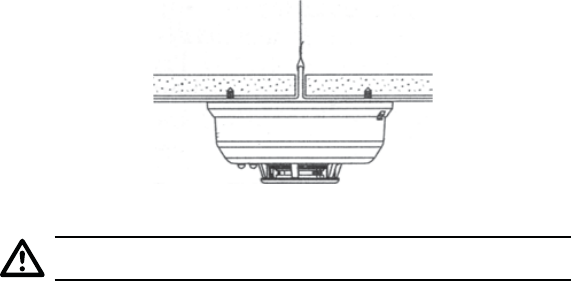
Figure 5: Montez le détecteur sur le support de plafond.
N’ATTACHEZ PAS le détecteur à des panneaux amovibles du plafond.
Attachez le détecteur sur le panneau comme le montre le Figure 5.
Les housses à poussière permettent de limiter effi cacement l’introduction de
poussière dans le compartiment du capteur du détecteur de fumée lors de
travaux. Toutefois, il est possible qu’elles n’empêchent pas complètement
l’entrée dans le détecteur de particules présentes dans l’air. On recommande
donc de retirer les détecteurs avant de commencer les travaux ou toute autre
activité productrice de poussière. Lorsque l’on remet le système en service,
il est important de veiller à retirer les housses à poussière de tout détecteur
resté en place pendant les travaux.
On n’utilisera pas les détecteurs de fumée avec des systèmes de protection
des détecteurs à moins que cette combinaison ait été évaluée et considérée
comme acceptable à ces fi ns.
Test du détecteur
Les détecteurs doivent être testés après l’installation et à la suite de la mainte-
nance périodique. Le Modèle No. SD4-MC peut être testé de la façon suivante:
A. Interrupteur de test
1. Un interrupteur de test en retrait se trouve sur le boîtier du détecteur (voir
la Figure 6).
2. Maintenez appuyé l’interrupteur de test en retrait pendant un minimum
de 5 secondes. Utilisez un petit tournevis ou une clé hexagonale au
diamètre maximum de 0,18 pouce (le détecteur déclenchera l’alarme et
enverra un signal de transmission au récepteur. Si l’outil est retiré de
l’interrupteur en retrait, la sonnerie s’interrompra)
Si le détecteur se trouve dans les limites de sensibilité indiquées, le voyant
DEL sur le détecteur clignotera une fois par seconde et l’avertisseur doit re-
tentir dans un délai de 3 secondes.
Interrupteur de test
Voyant DEL vert
Voyant DEL rouge APPUYEZ SUR L’INTERRUPTEUR
EN RETRAIT AVEC UN OUTIL
D’UN DIAMÈTRE MAXIMUM DE 0,18’
Figure 6: Ouverture de l’interrupteur de test en retrait
B. Test d’entrée de la fumée
Tenez un bâtonnet ou une mèche de coton enfl ammé(e) à côté du détecteur
et souffl ez pour diriger la fumée dans le détecteur jusqu’à ce que l’alarme
retentisse. Il est également possible de vaporiser un aérosol à proximité de
l’appareil.
Figure 7: Test avec une mèche
Mèche de coton
Test de la puissance du signal
Un test doit être effectué avant l’installation pour vérifi er que la communi-
cation s’effectue facilement avec le récepteur et après l’installation. Le pro-
priétaire / utilisateur doit également tester l’appareil au moins une fois par
semaine.
Test de la programmation
On procédera à un test avant l’installation pour vérifi er que l’adresse du
transmetteur du détecteur est bien programmée à celle du récepteur, et que le
système est opérationnel.
Maintenance
REMARQUE : Le détecteur doit être mis hors tension avant de procéder à
toute opération de maintenance, en retirant la pile du détecteur.
1. Pour veiller à bien éteindre l’appareil, la pile doit être retirée du détecteur
pendant un minimum de 20 secondes avant la maintenance.
2. Passez le couvercle à l’aspirateur ou servez-vous d’air en aérosol pour
retirer toute poussière ou tout débris.
3. À l’aide d’un aspirateur ou d’un vaporisateur à air, nettoyez avec soin la
poussière et les débris du couvercle du détecteur de fumée.
4. Réinstallez le détecteur et testez-le. (Voir la rubrique relative au Test).
Que faire en cas d’incendie
• Ne paniquez pas ; restez calme. Suivez le plan d’évacuation de la famille.
• Sortez de la maison le plus rapidement possible. Ne vous arrêtez pas
pour vous habiller ou ramasser quoi que ce soit.
• Touchez les portes avec le dos de votre main avant de les ouvrir. Si une
porte est froide, ouvrez-la lentement. N’ouvrez pas une porte brûlante.
Gardez la porte et les fenêtres fermées, à moins que vous deviez vous
échapper par celles-ci.
• Appelez les services de lutte contre l’incendie à partir de l’extérieur du
bâtiment. Donnez votre adresse, et ensuite votre nom.
• Couvrez votre nez et votre bouche avec un chiffon (humide de
préférence). Prenez de courtes respirations peu profondes.
• Retrouvez-vous dans un lieu de rencontre prévu à l’avance à l’extérieur de
votre maison, et comptez-vous pour vérifi ez que tout le monde est en lieu
sûr.
• Ne rentrez jamais dans le bâtiment en feu quelle qu’en soit la raison.
• Contactez vos services de lutte contre l’incendie pour obtenir des sug-
gestions et des idées en ce qui concerne l’amélioration des conditions de
sécurité dans votre maison.
AVIS D’INFORMATION IC:
Toute modi cation non autorisée pourrait annuler autorisation votre
d’utiliser l’équipement. Cet appareil est conforme avec Industrie Canada
exemptes de licence RSS ou les normes. Son fonctionnement est sujet
aux deux conditions suivantes: (1) cet appareil ne doit pas émettre de
brouillage nuisible, et (2) cet appareil doit accepter toute interférence
reçue, y compris les interférences pouvant entraîner un fonctionnement
indésirable du dispositif. Cet équipement a été testé et déclaré con-
forme aux limites d’un appareil numérique de classe B, conformément
à l’article 15 des règlements FCC. Ces limites sont conçues pour fournir
une protection raisonnable contre les interférences nuisibles dans une
installation résidentielle. Cet équipement génère, utilise et peut émettre
de l’énergie de fréquence radio et si pas installé et utilisé conformément
aux instructions, peut causer des interférences nuisibles aux communi-
cations radio. Cependant, il n’y a aucune garantie que des interférences
n’interviendront pas dans une installation particulière. Si cet équi-
pement provoque des interférences nuisibles à la réception radio ou
télévision, ce qui peut être déterminée en éteignant et rallumant l’équi-
pement, l’utilisateur est encouragé à essayer de corriger l’interférence
par une ou plusieurs des mesures suivantes:
• Réorientez ou déplacez l’antenne de réception.
• Augmenter la distance entre l’équipement et le récepteur
• Branchez l’appareil dans une prise sur un circuit différent de celui
auquel est connecté le récepteur.
• Consultez le revendeur ou un technicien expérimenté en radio/
télévision pour aide).

Spéci cations
Source d’alimentation:
Hauteur:
Diamètre:
Fourchette de température ambiante de fonctionnement :
Fourchette de taux d’humidité:
Homologation:
Une pile au lithium de 3 volts CR123A (livrée avec l’ap-
pareil). (Remplacez-la par une pile Panasonic CR123A
ou Duracell DL123A). Ces piles peuvent être achetées
dans de nombreux magasins de détail locaux. Vous
pouvez également commander des piles de rechange
en ligne à www.Silentcall.com.
2,3 pouces (58 mm)
5,3 pouces (135 mm) (avec support de montage) Poids
8,5 oz. (241 g) (sans la pile)
40° à 100°F (4,4° à 37,8C)
0 % à 95 % d’humidité relative
Conformité à la norme CAN/ULC-S531-02 testée
Pour les demandes d’indemnisation/réparations dans le cadre de la
garantie, veuillez contacter le fabricant :
Silent Call Communications
5095 Williams Lake Road
Waterford, MI 48329
800-572-5227
Veuillez consulter www.Silentcall.com