Silex Technology SX510 Serial Device Server User Manual SX 500 510 Manual 122208
Silex Technology, Inc. Serial Device Server SX 500 510 Manual 122208
UserManual.wiki
>
Silex Technology
>
SX510 User Manual
>
Users Manual
Contents
1.
Users Manual
2.
Usures Manual
Users Manual
Navigation menu
Upload a User Manual
Namespaces
Wiki Guide
HTML
PDF
Info
Views
User Manual
Discussion / Help
Navigation
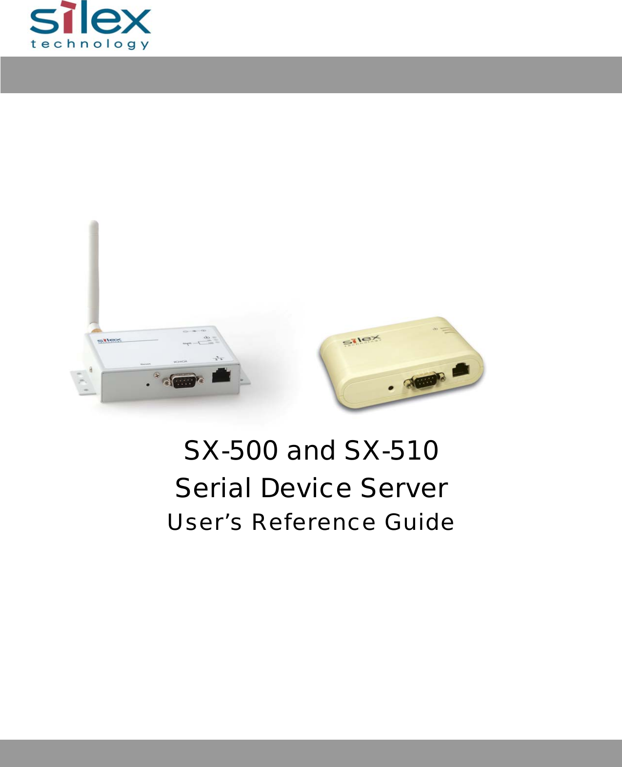

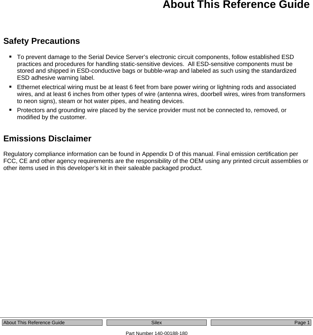

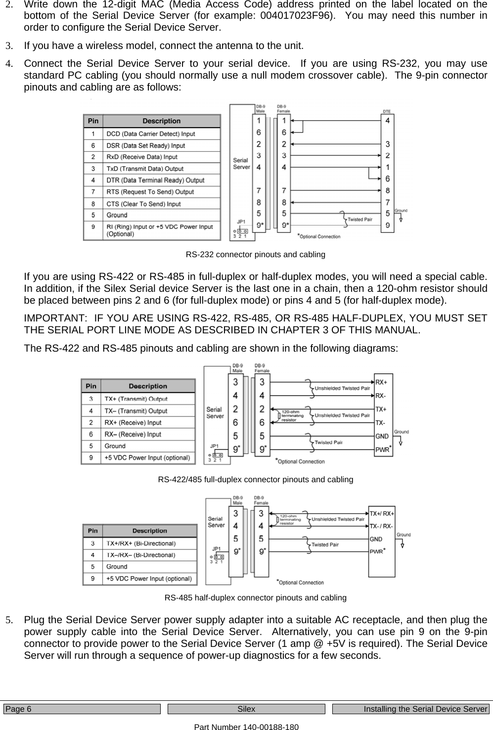
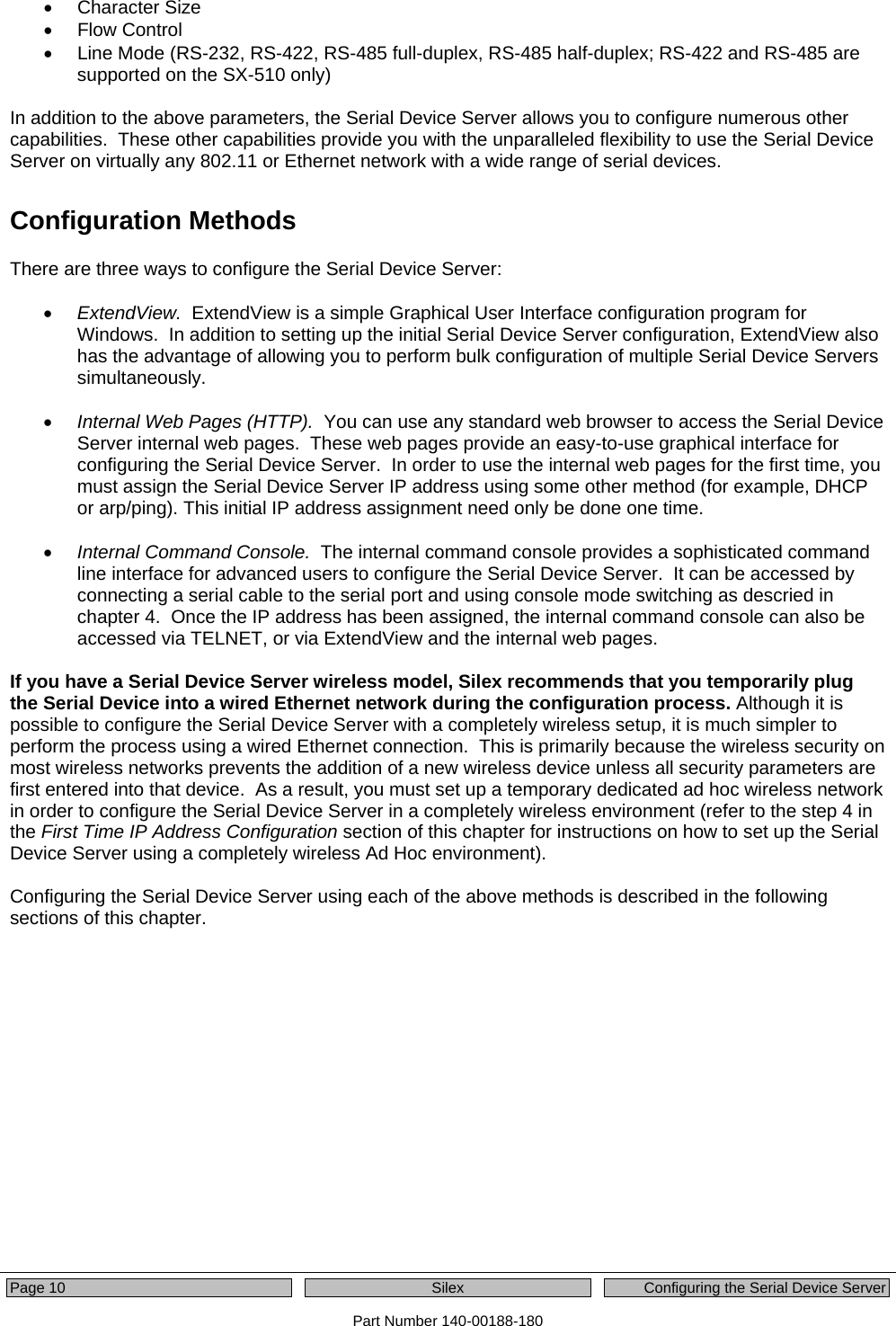
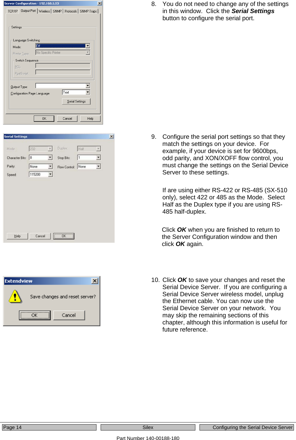
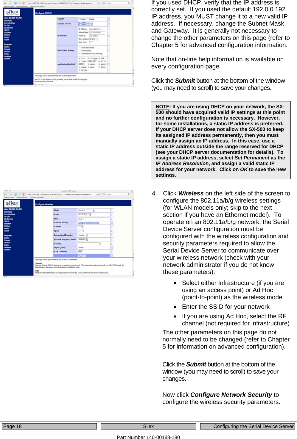
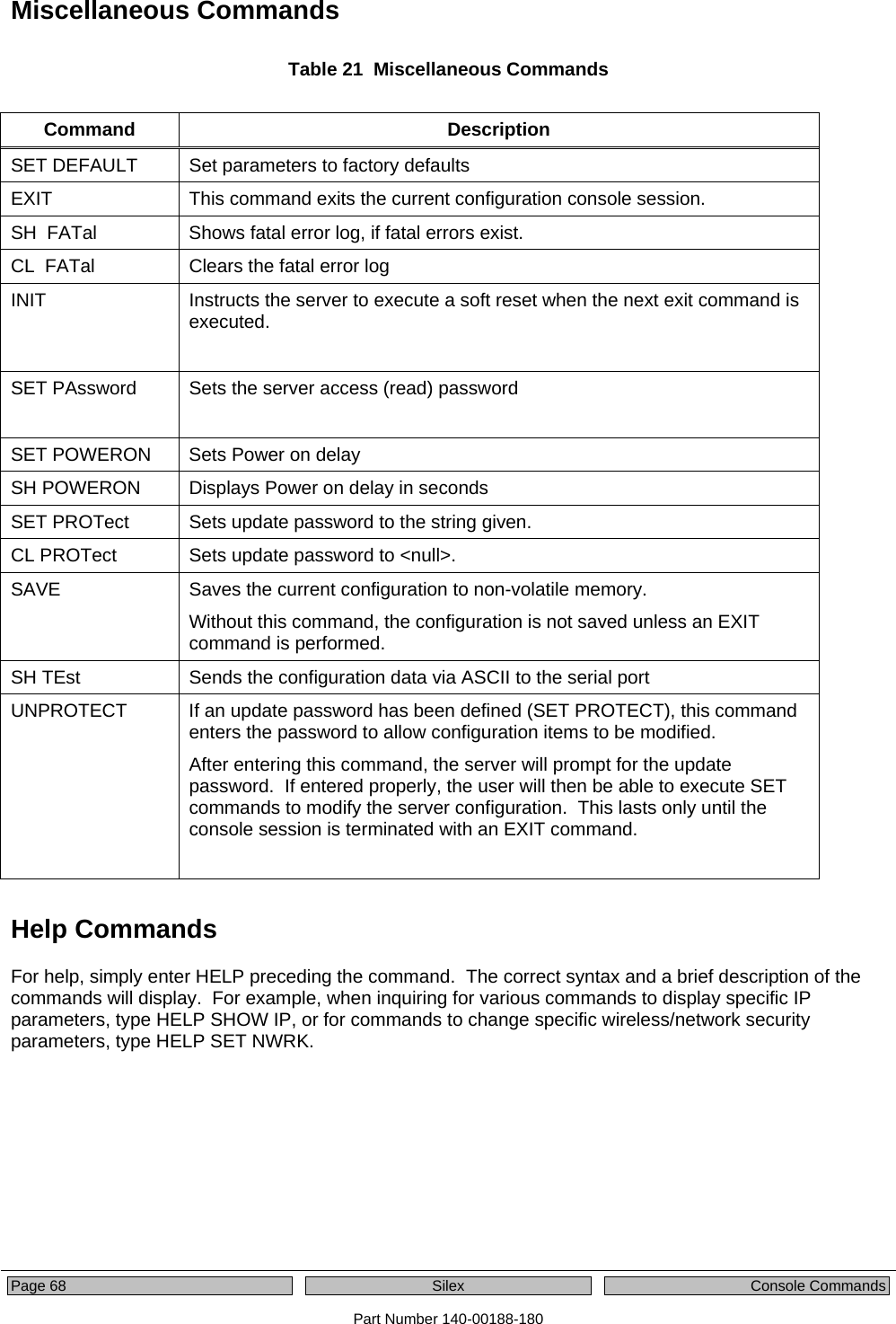
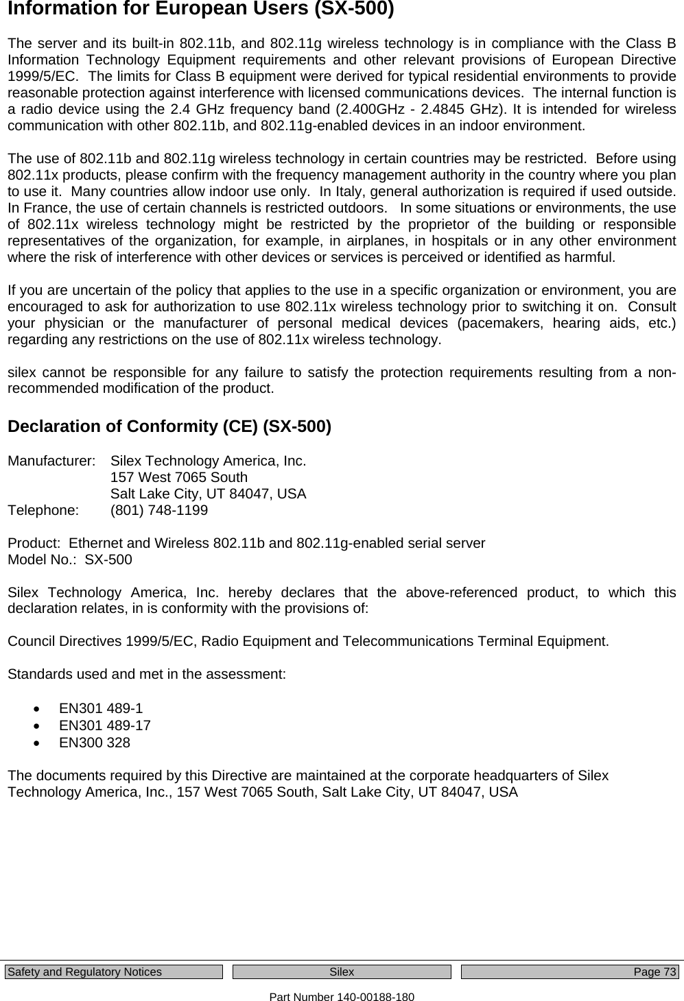
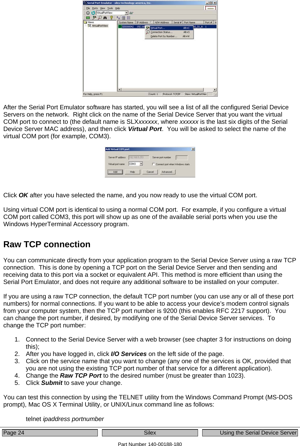
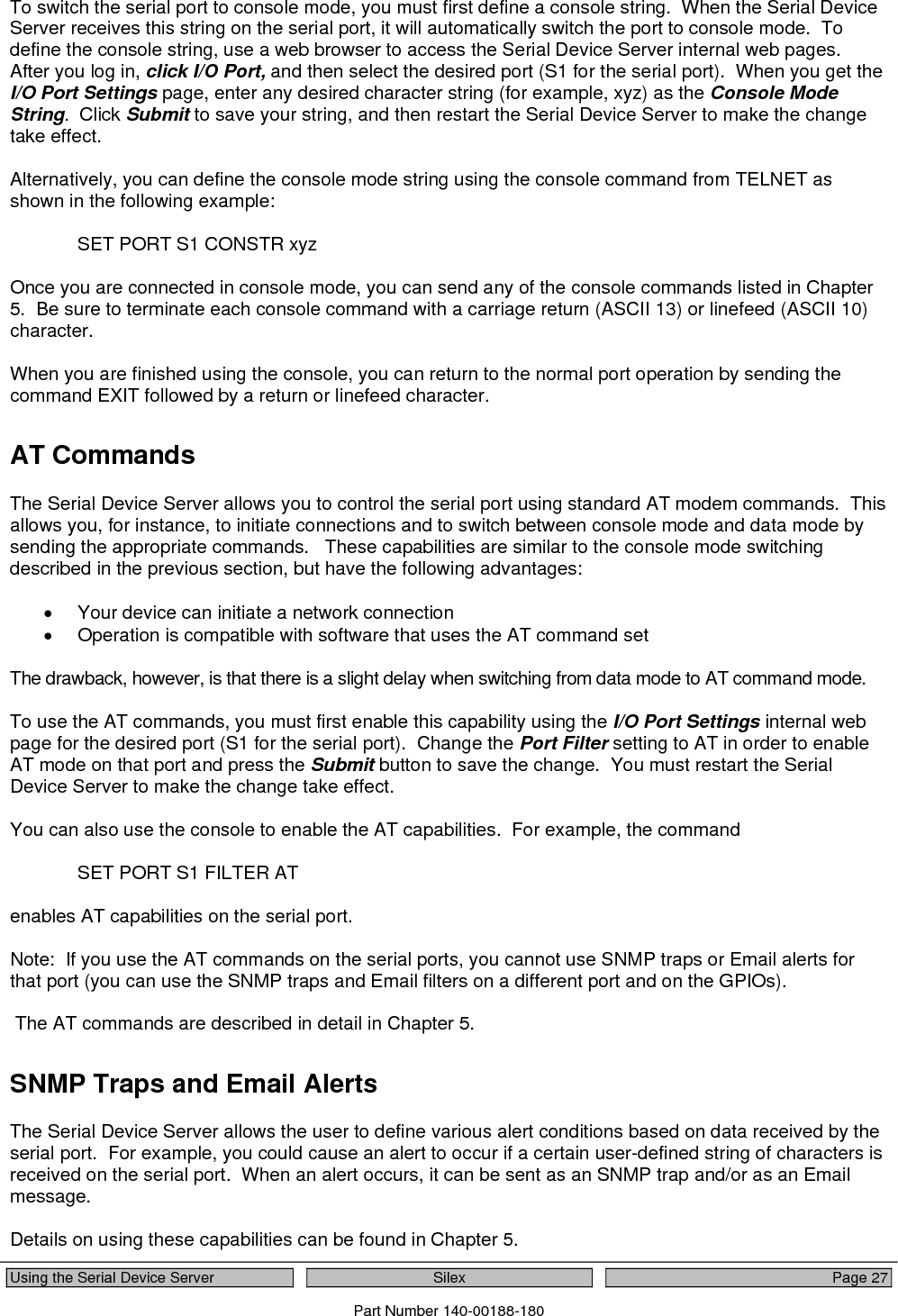
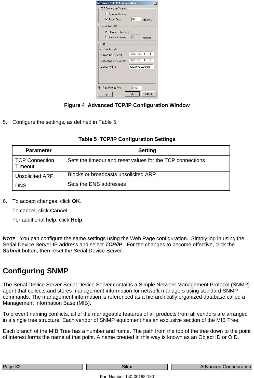
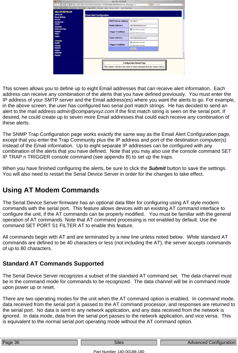
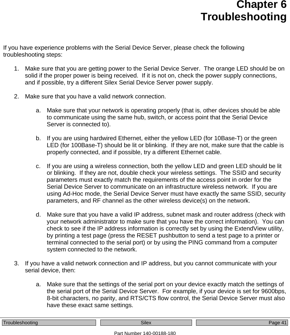
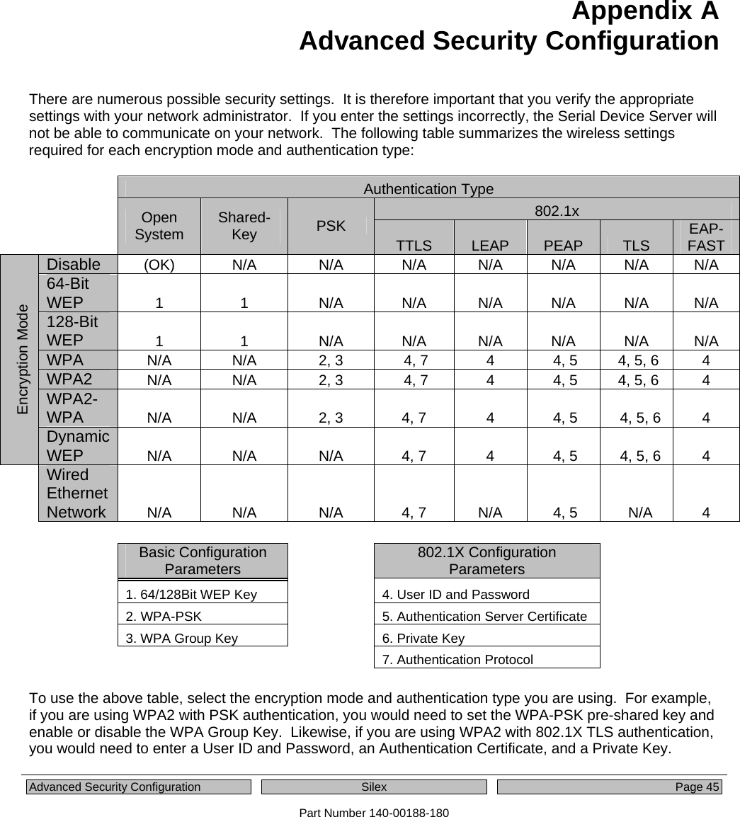
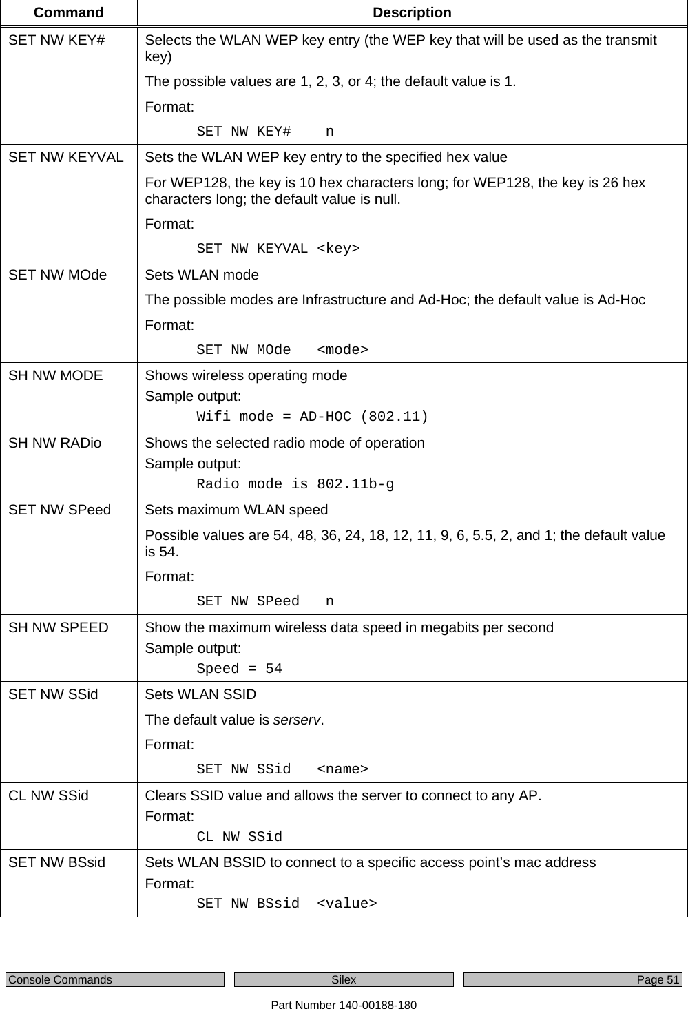
![Page 20 Silex Configuring the Serial Device Server Part Number 140-00188-180 telnet aa.bb.cc.dd where aa.bb.cc.dd is the IP address of the Serial Device Server (for example, telnet 192.168.5.6). 2. Press <ENTER> and then enter the password access at the # prompt. Press <ENTER> at the Enter Username> prompt. When you see the Local> prompt, you can enter console commands. 3. If you used the default 192.0.0.192 IP address to connect to the Serial Device Server, you MUST change it to a new valid IP address. If necessary, you must also change the Subnet Mask and Router (Gateway). The commands are as follows: SET IP ADDRESS aa.bb.cc.dd SET IP SUBNET aa.bb.cc.dd SET IP ROUTER aa.bb.cc.dd where aa.bb.cc.dd is the IP address of the Serial Device Server. You can use the command SHOW IP to verify the IP address settings. 4. Enter the basic wireless settings as follows: SET NW SSID <name> [where <name> is the SSID for your network] SET NW MODE <mode> [where mode is INFRASTRUCTURE or AD-HOC] SET NW CHANNEL n [where n is 1 to 11; this is only required for AD-HOC MODE] 5. Use the appropriate SET NW command to set wireless encryption mode and authentication type (check with your network administrator for the proper settings if you do not know them): SET NW ENC <mode> [sets encryption mode, where <mode> is WPA, WPA2, 64, 128, or WPA2-WPA] SET NW AUTHTYPE <type> [sets authentication type, where <type> is OPEN, SHARED, TTLS, PEAP, WPA-PSK, LEAP, TLS, or FAST]. For WPA2-PSK or WPA, enter the command: SET NW WPAPSK <psk> [sets pre-shared key for WPA2 or WPA, where <psk> is the key] SET NW WPAGROUP <state> [enables or disables WPA group key mode, where <state> is ENABLED or DISABLED; default is DISABLED] For WEP (WEP64 or WEP128), use the following commands: SET NW KEYVAL <key> [Sets WEP key, where <key> is 10 hex characters for WEP64 or 26 hex characters for WEP128] SET NW KEY# n [sets the number of the WEP key that will be used as the transmit key, where n=1 to 4; default value is 1] Configuring 802.1X EAP authentication can be complex. Please refer to Appendix A and/or Appendix B for details of the required commands.](https://usermanual.wiki/Silex-Technology/SX510.Users-Manual/User-Guide-1053777-Page-26.png)
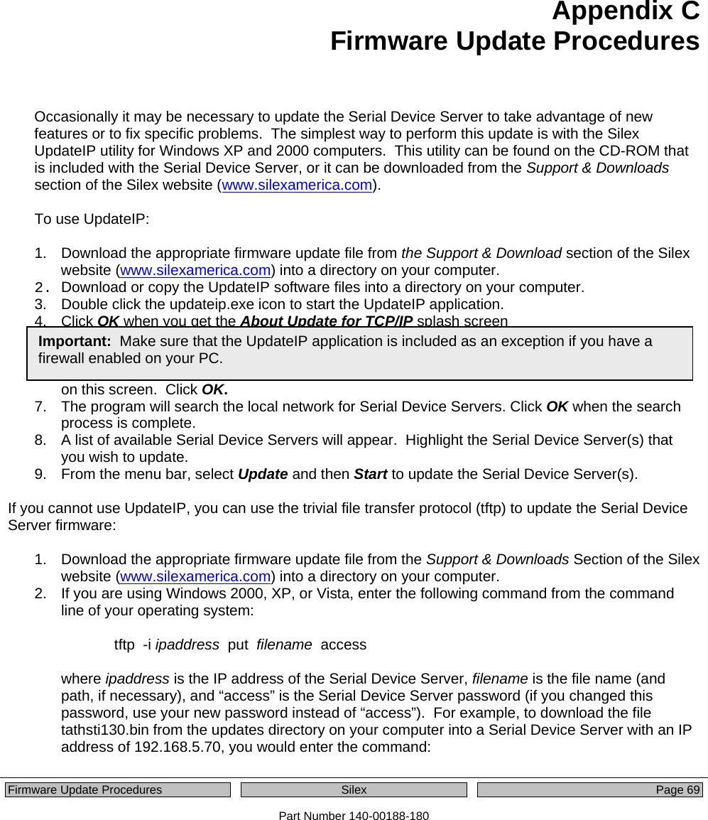
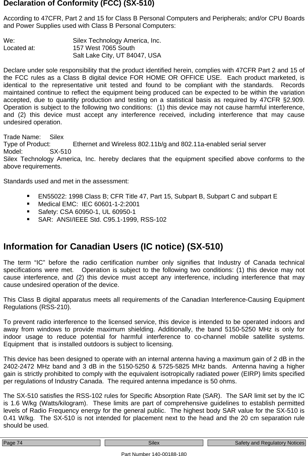
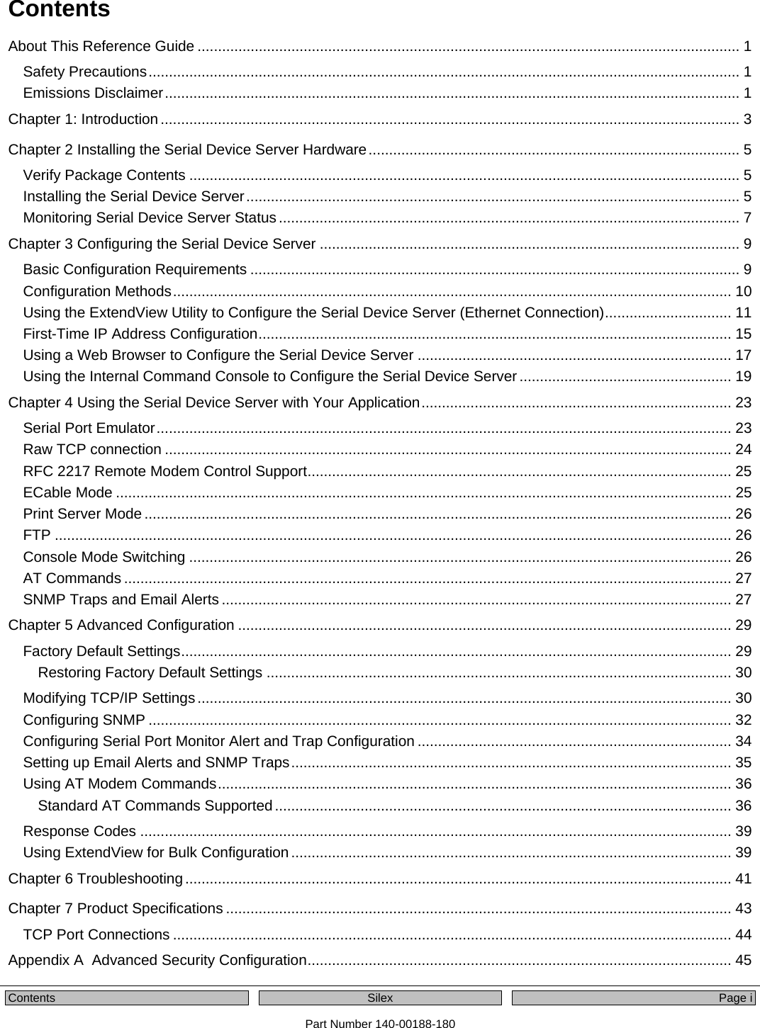
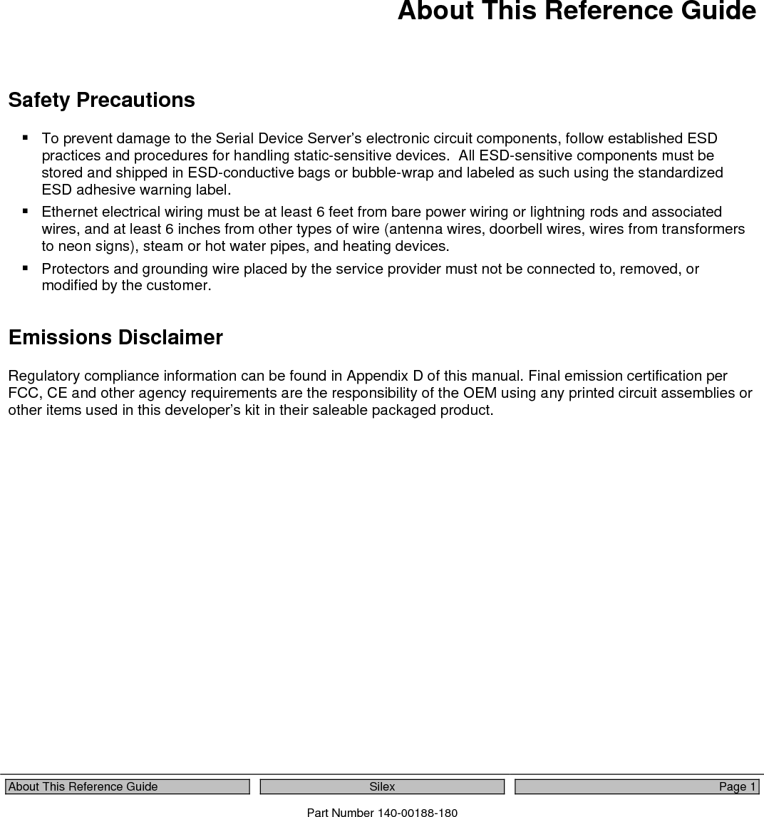
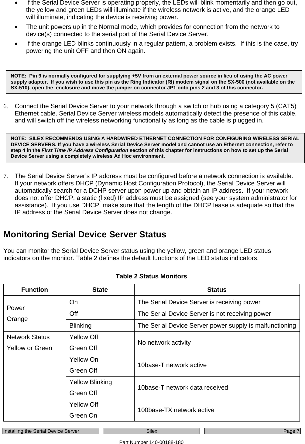
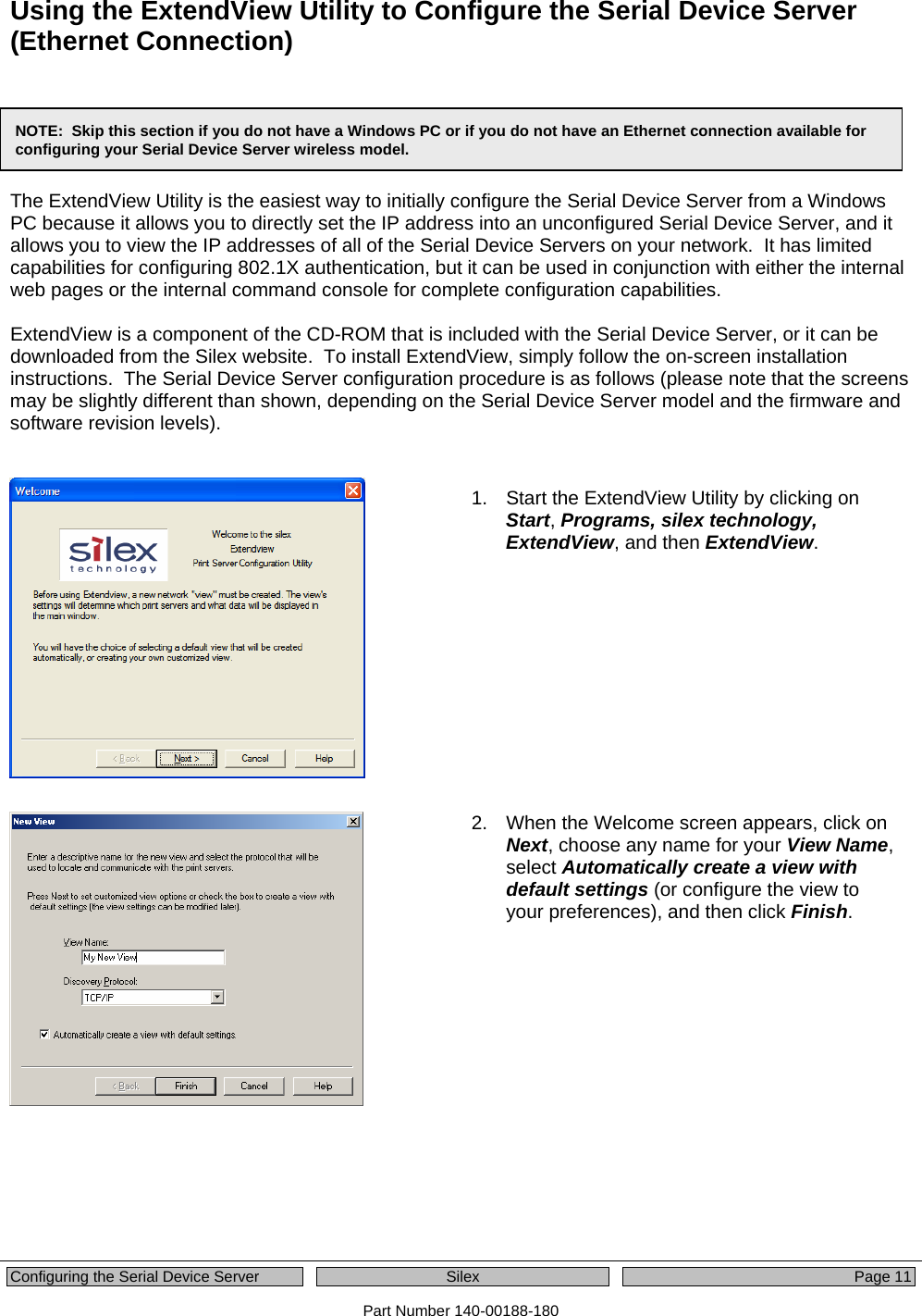
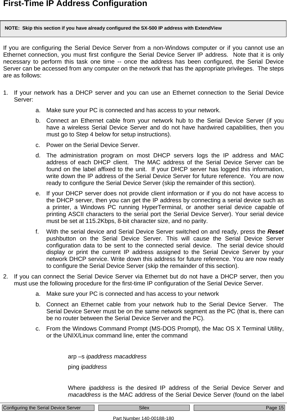
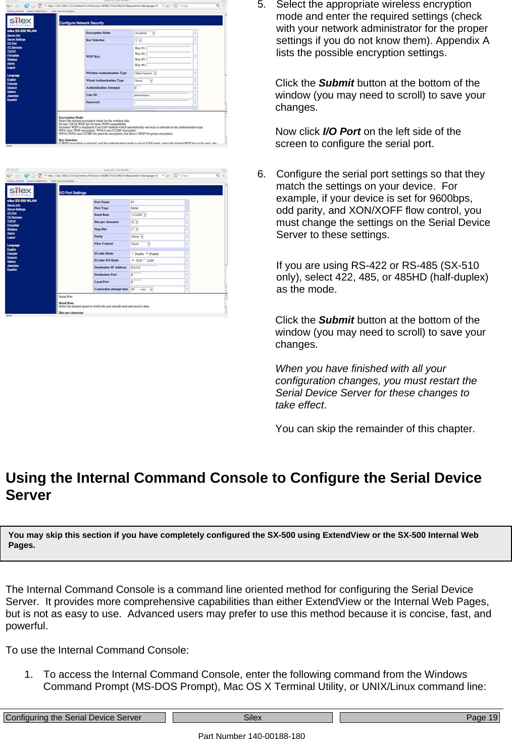
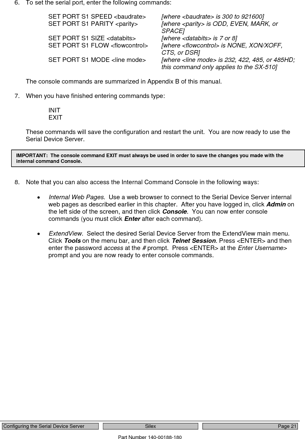
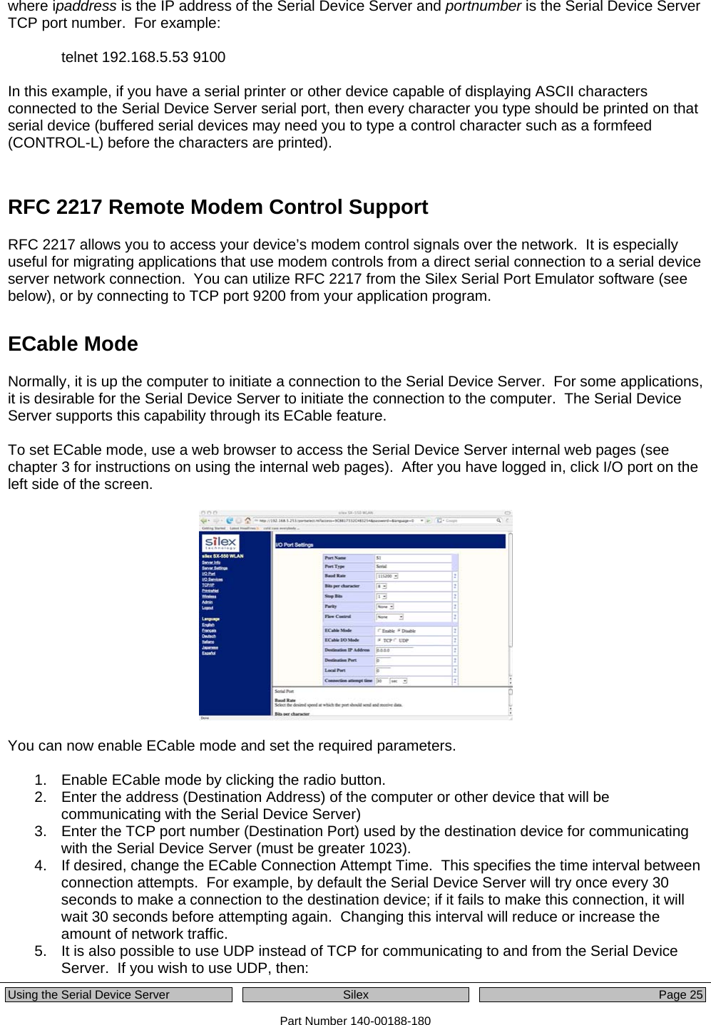
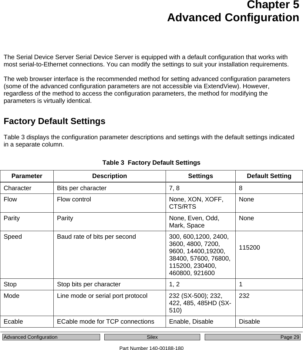
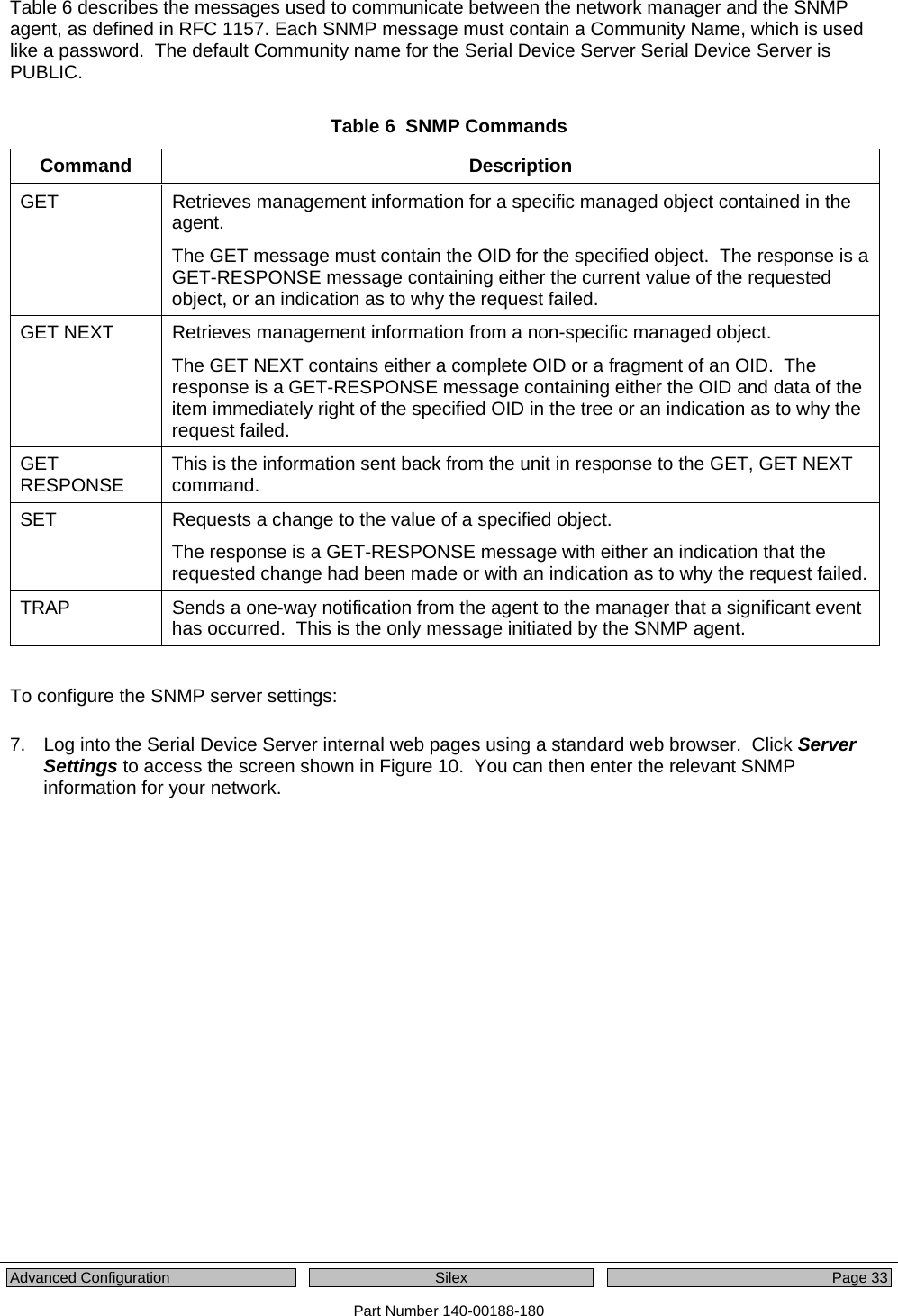
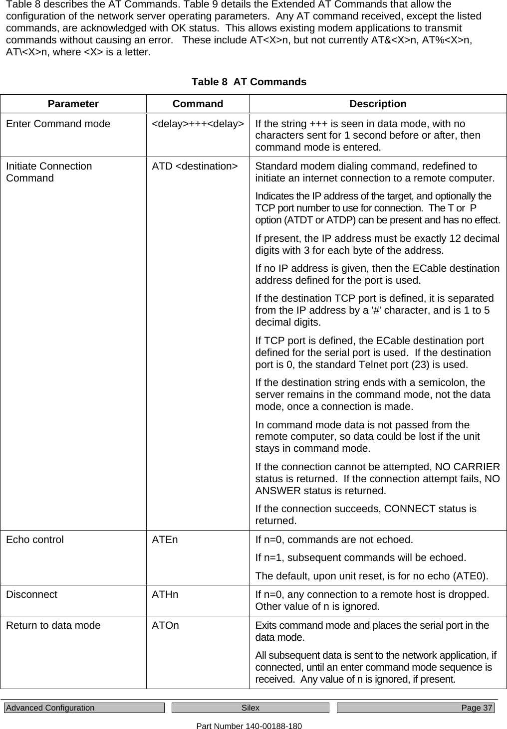
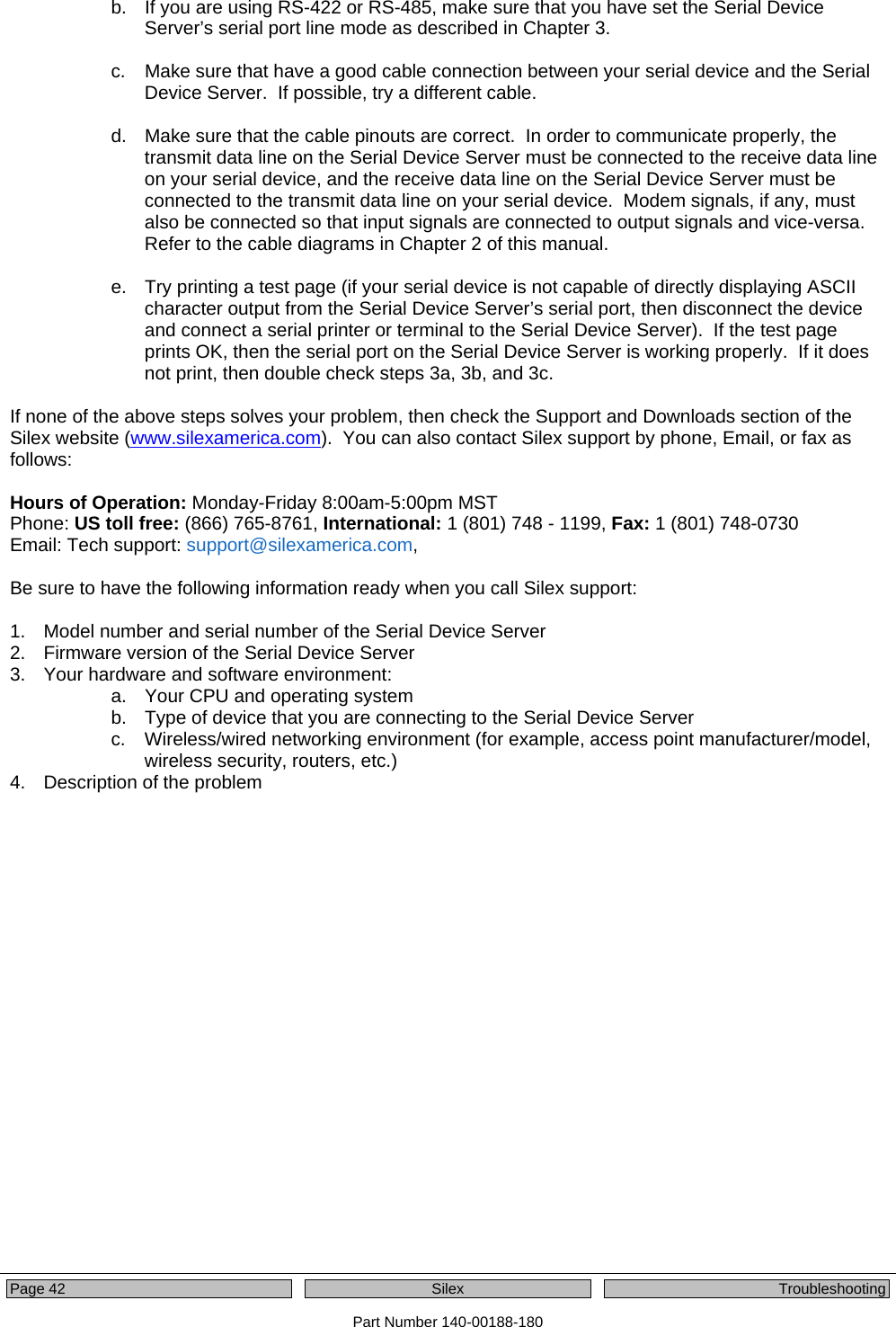
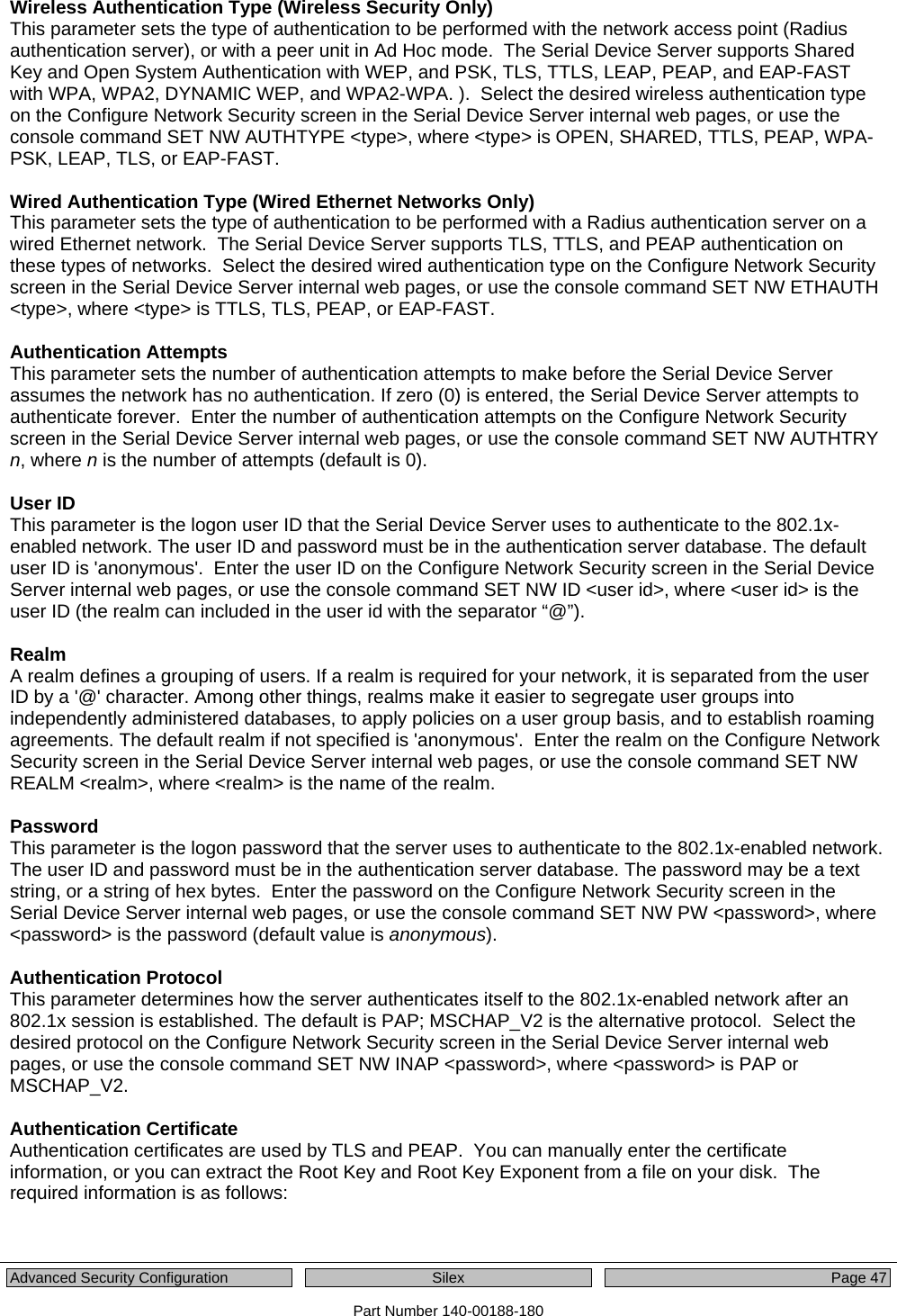
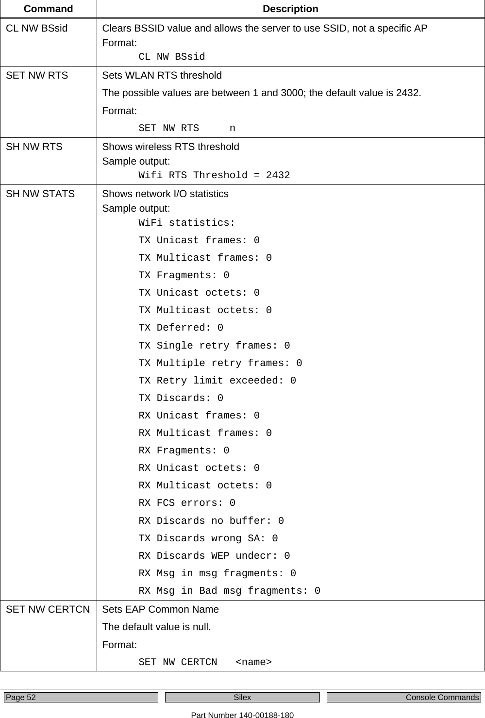
![Configuring the Serial Device Server Silex Page 21 Part Number 140-00188-180 6. To set the serial port, enter the following commands: SET PORT S1 SPEED <baudrate> [where <baudrate> is 300 to 921600] SET PORT S1 PARITY <parity> [where <parity> is ODD, EVEN, MARK, or SPACE] SET PORT S1 SIZE <databits> [where <databits> is 7 or 8] SET PORT S1 FLOW <flowcontrol> [where <flowcontrol> is NONE, XON/XOFF, CTS, or DSR] SET PORT S1 MODE <line mode> [where <line mode> is 232, 422, 485, or 485HD; this command only applies to the SX-510] The console commands are summarized in Appendix B of this manual. 7. When you have finished entering commands type: INIT EXIT These commands will save the configuration and restart the unit. You are now ready to use the Serial Device Server. EXIT 8. Note that you can also access the Internal Command Console in the following ways: • Internal Web Pages. Use a web browser to connect to the Serial Device Server internal web pages as described earlier in this chapter. After you have logged in, click Admin on the left side of the screen, and then click Console. You can now enter console commands (you must click Enter after each command). • ExtendView. Select the desired Serial Device Server from the ExtendView main menu. Click Tools on the menu bar, and then click Telnet Session. Press <ENTER> and then enter the password access at the # prompt. Press <ENTER> at the Enter Username> prompt and you are now ready to enter console commands. IMPORTANT: The console command EXIT must always be used in order to save the changes you made with the internal command Console.](https://usermanual.wiki/Silex-Technology/SX510.Users-Manual/User-Guide-1053777-Page-27.png)
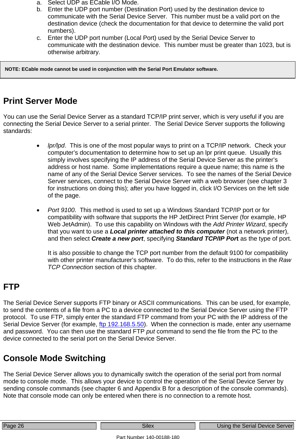
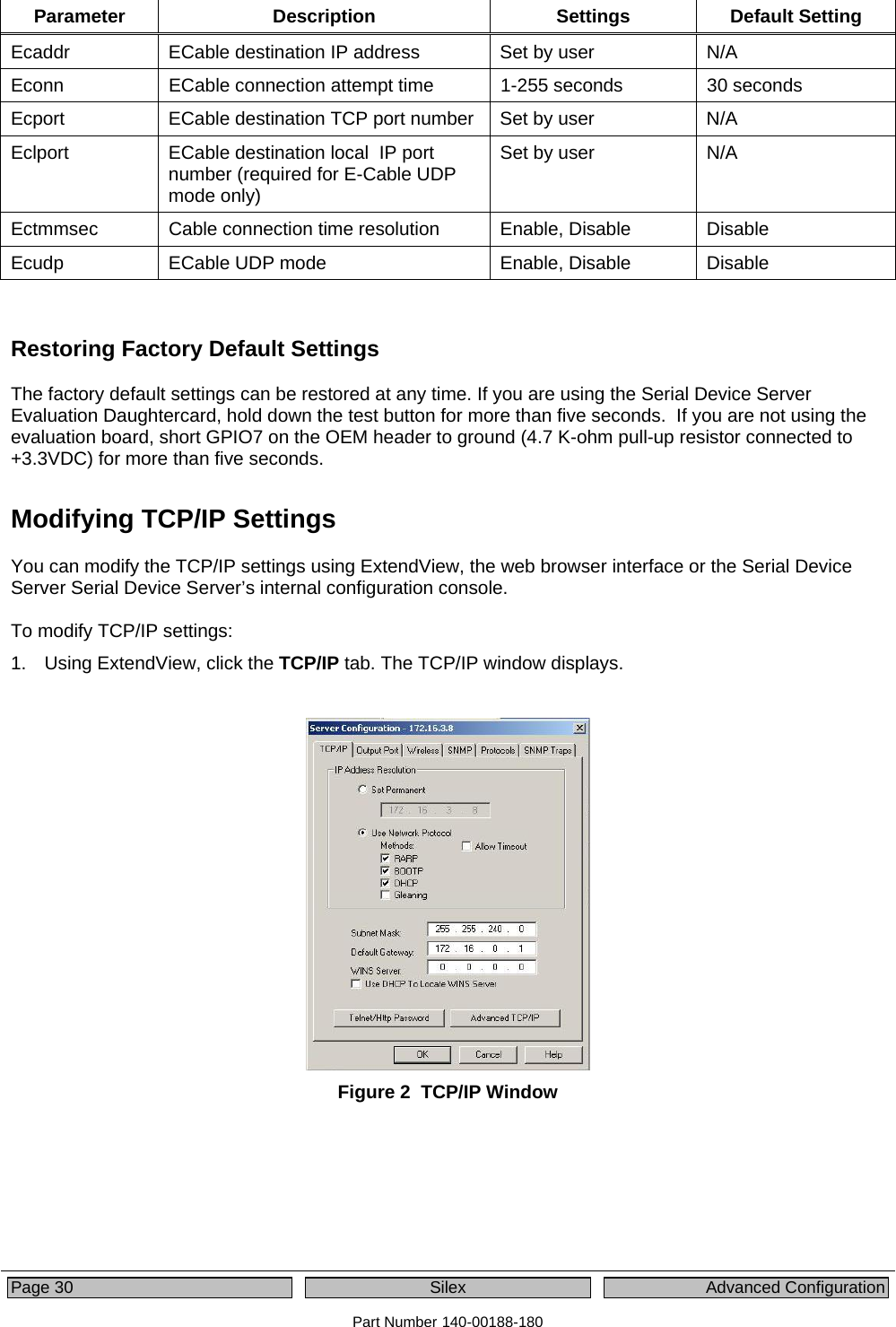
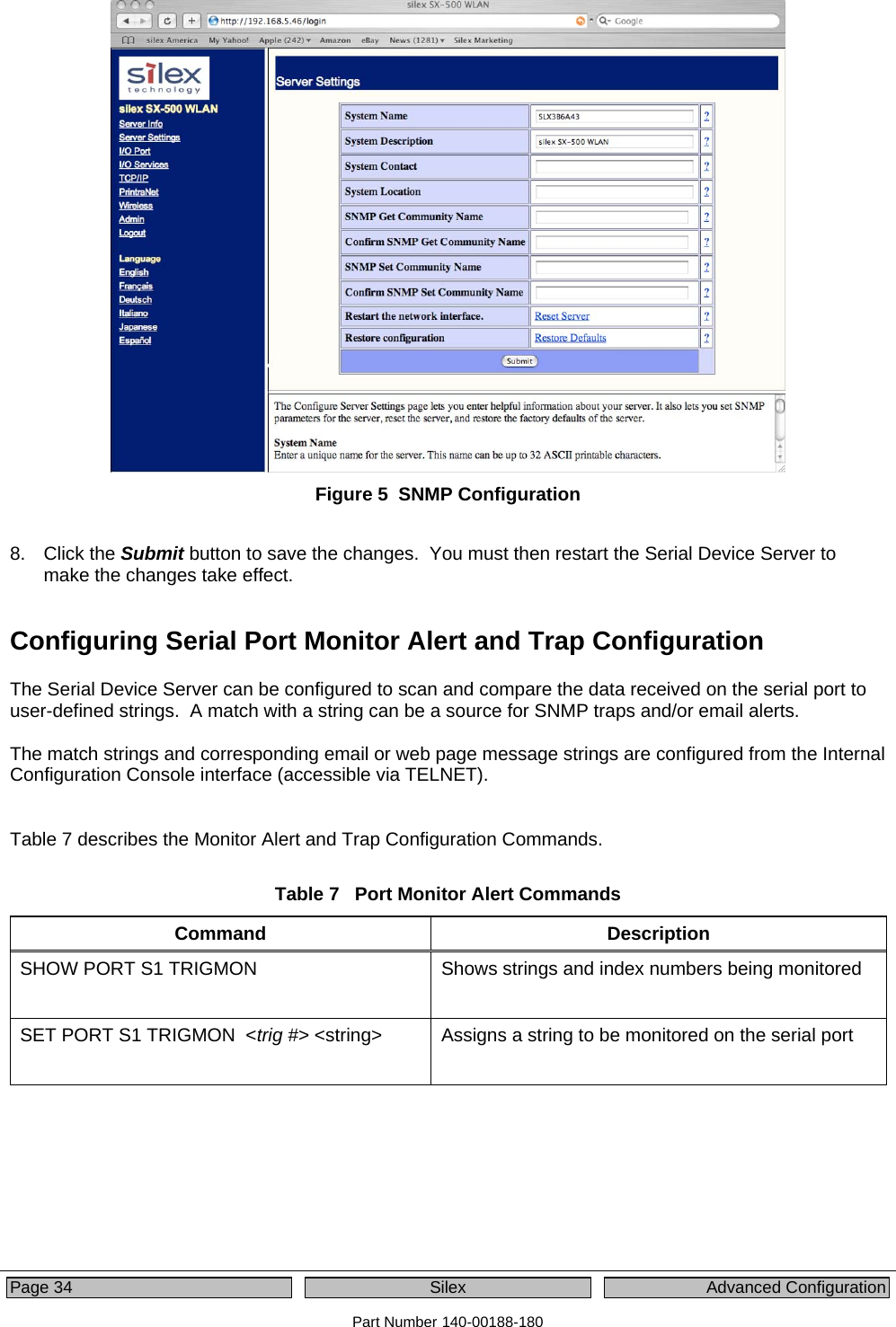
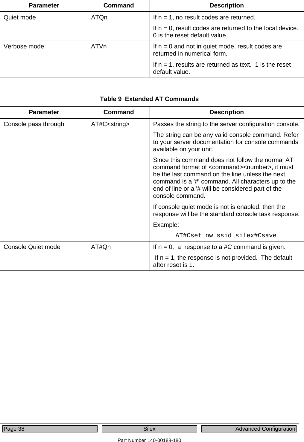

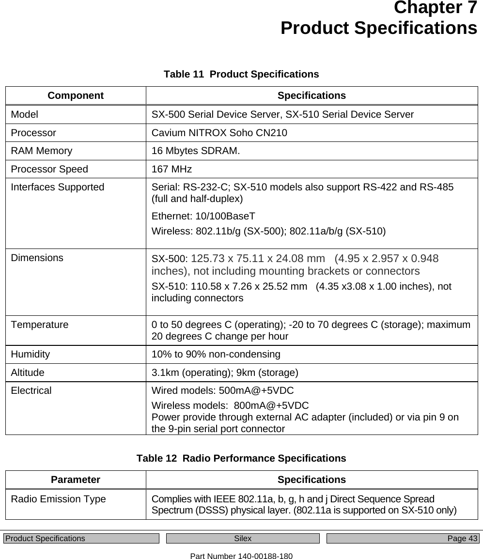

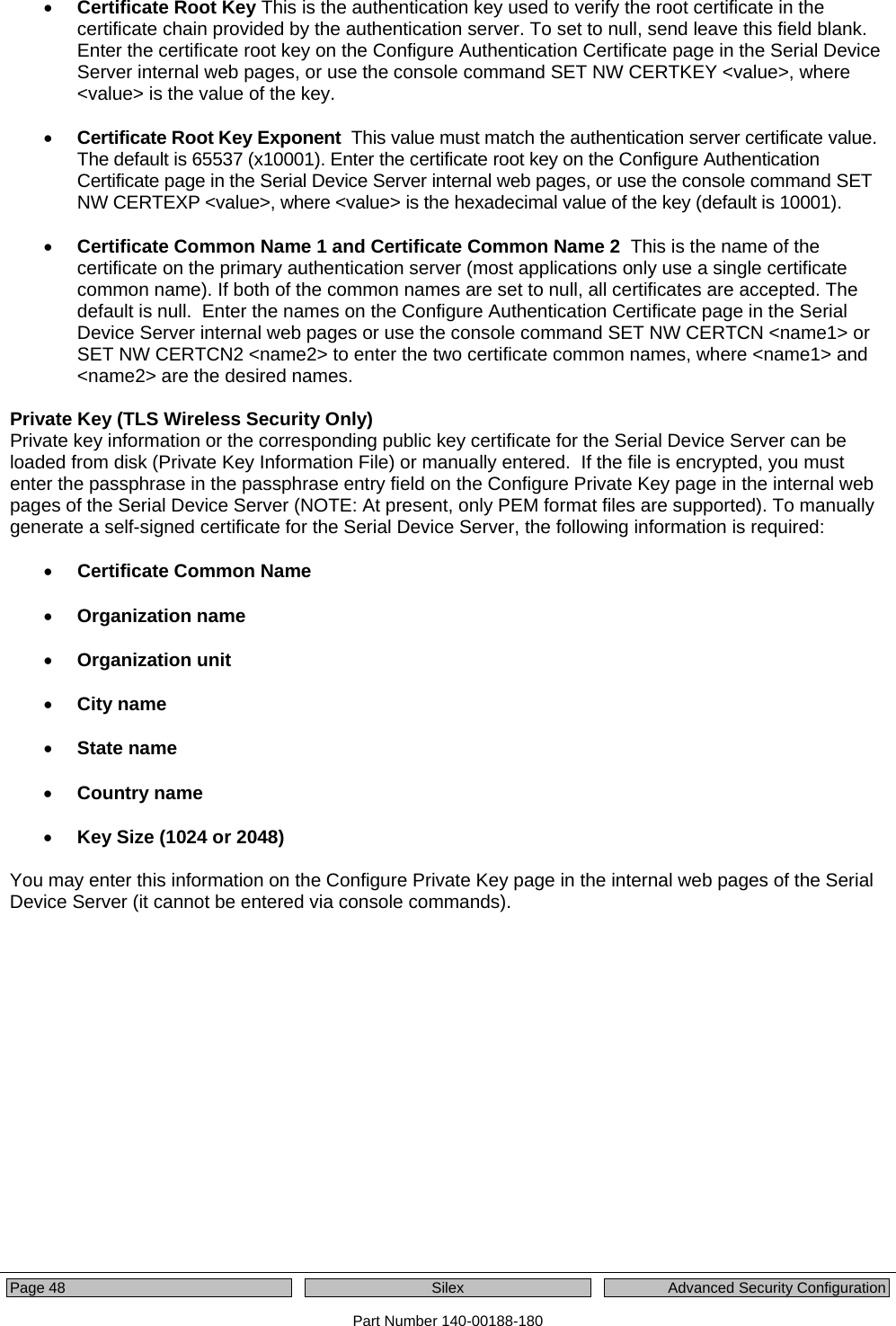
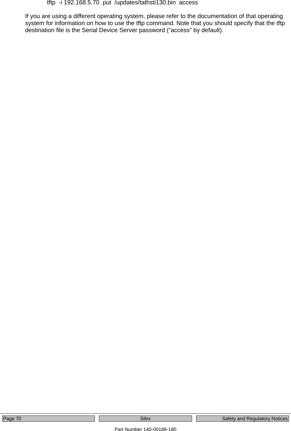
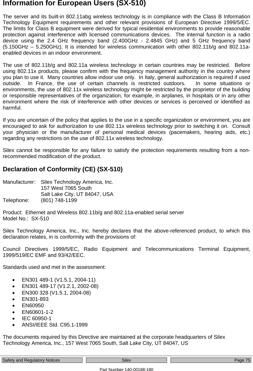
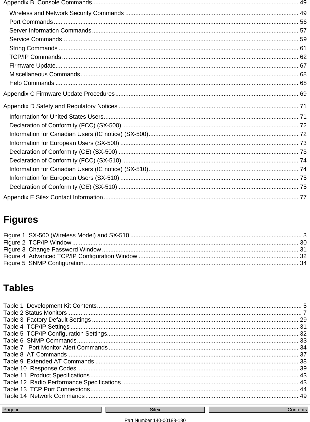
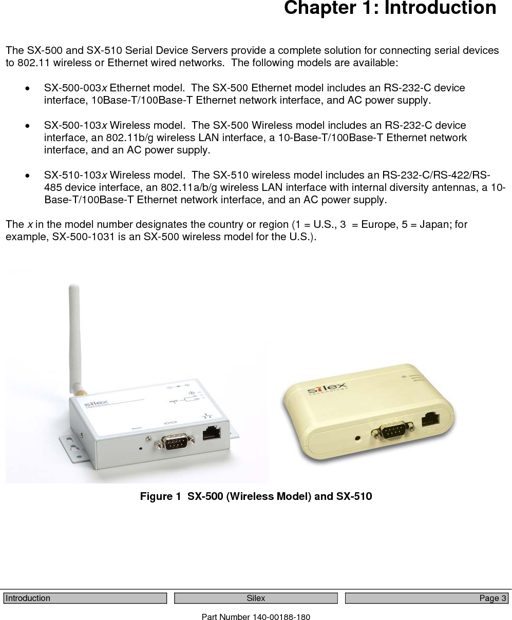
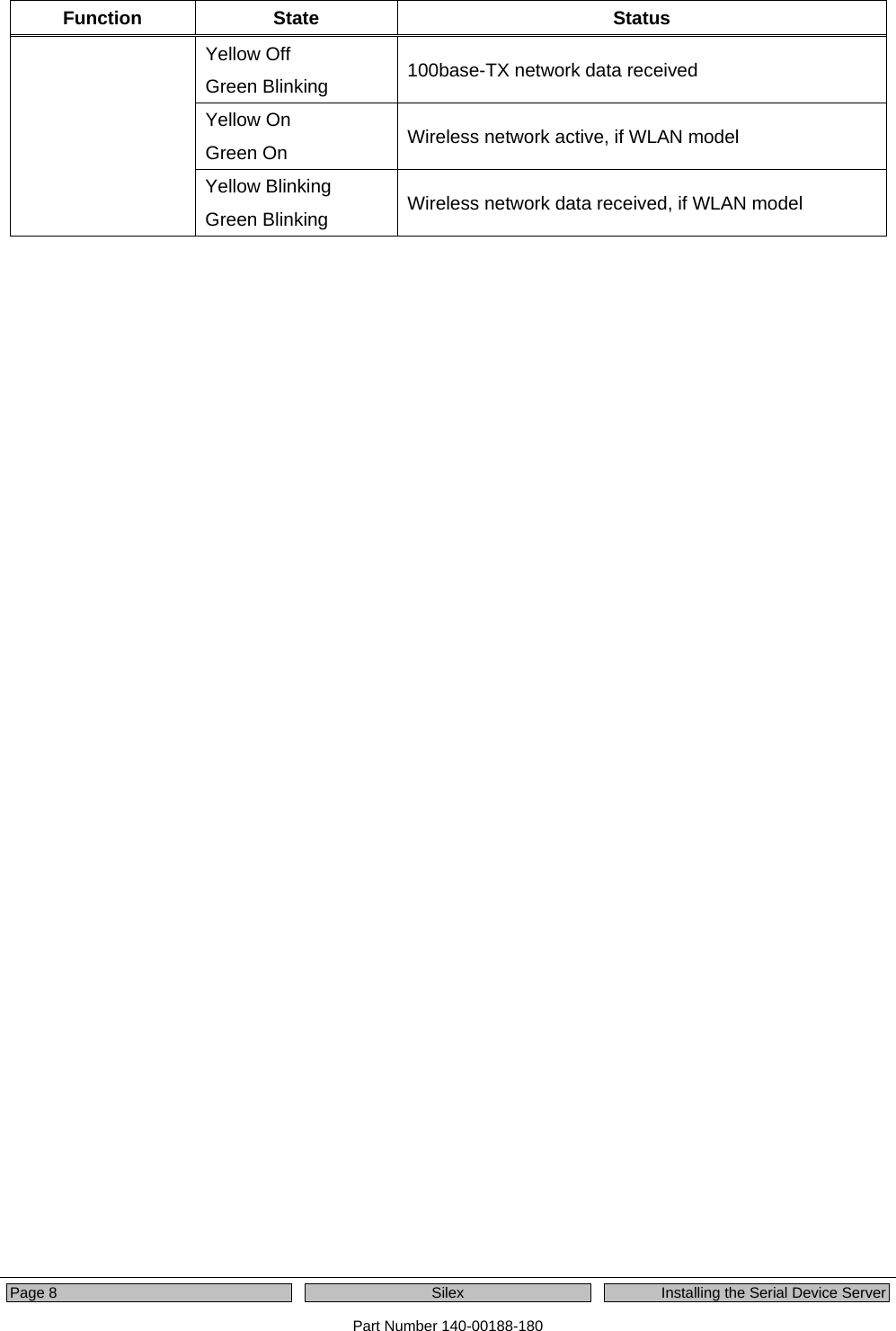
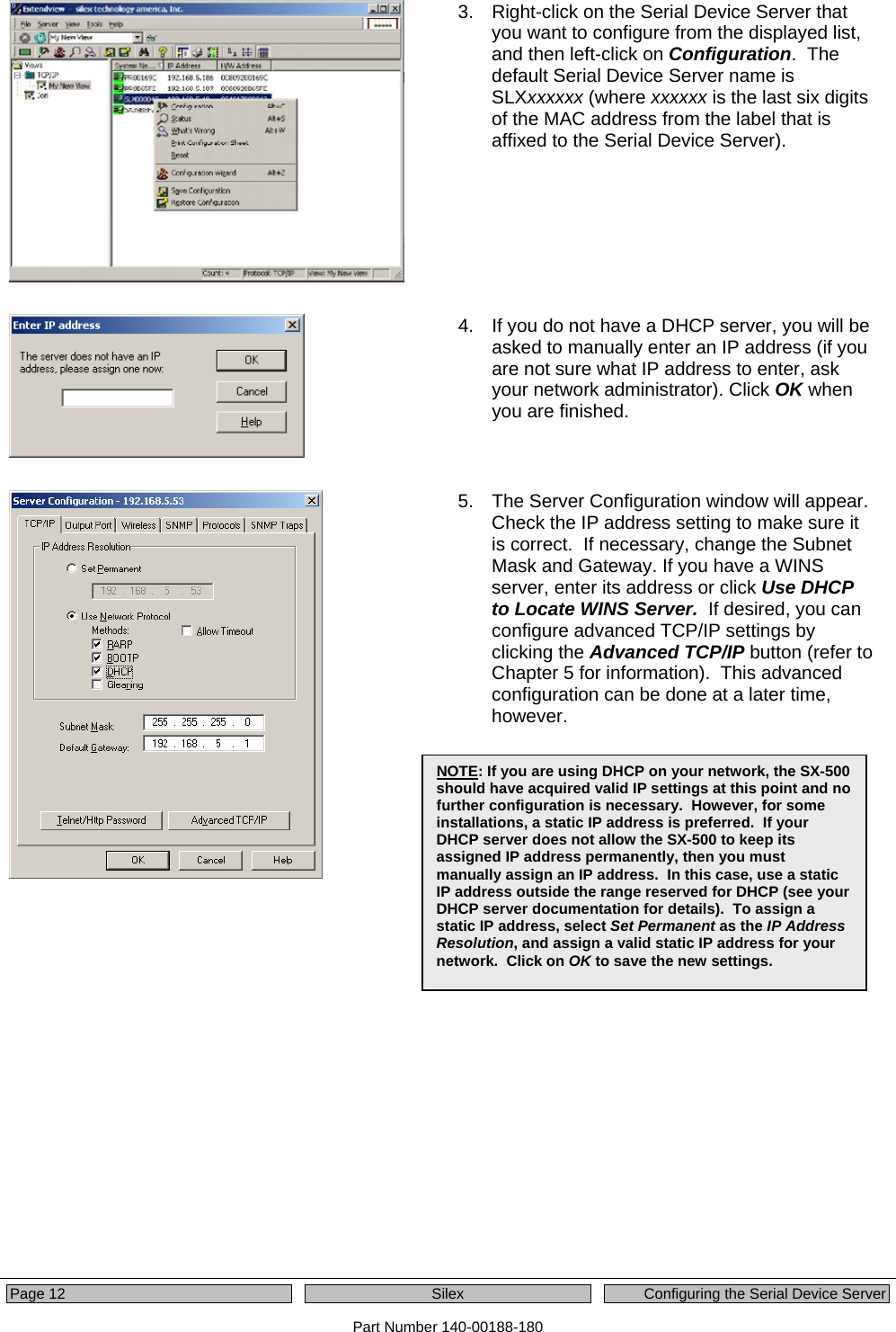
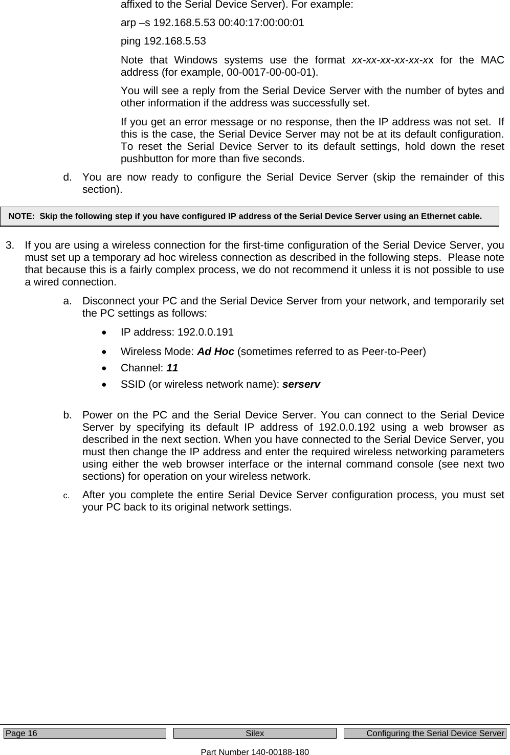
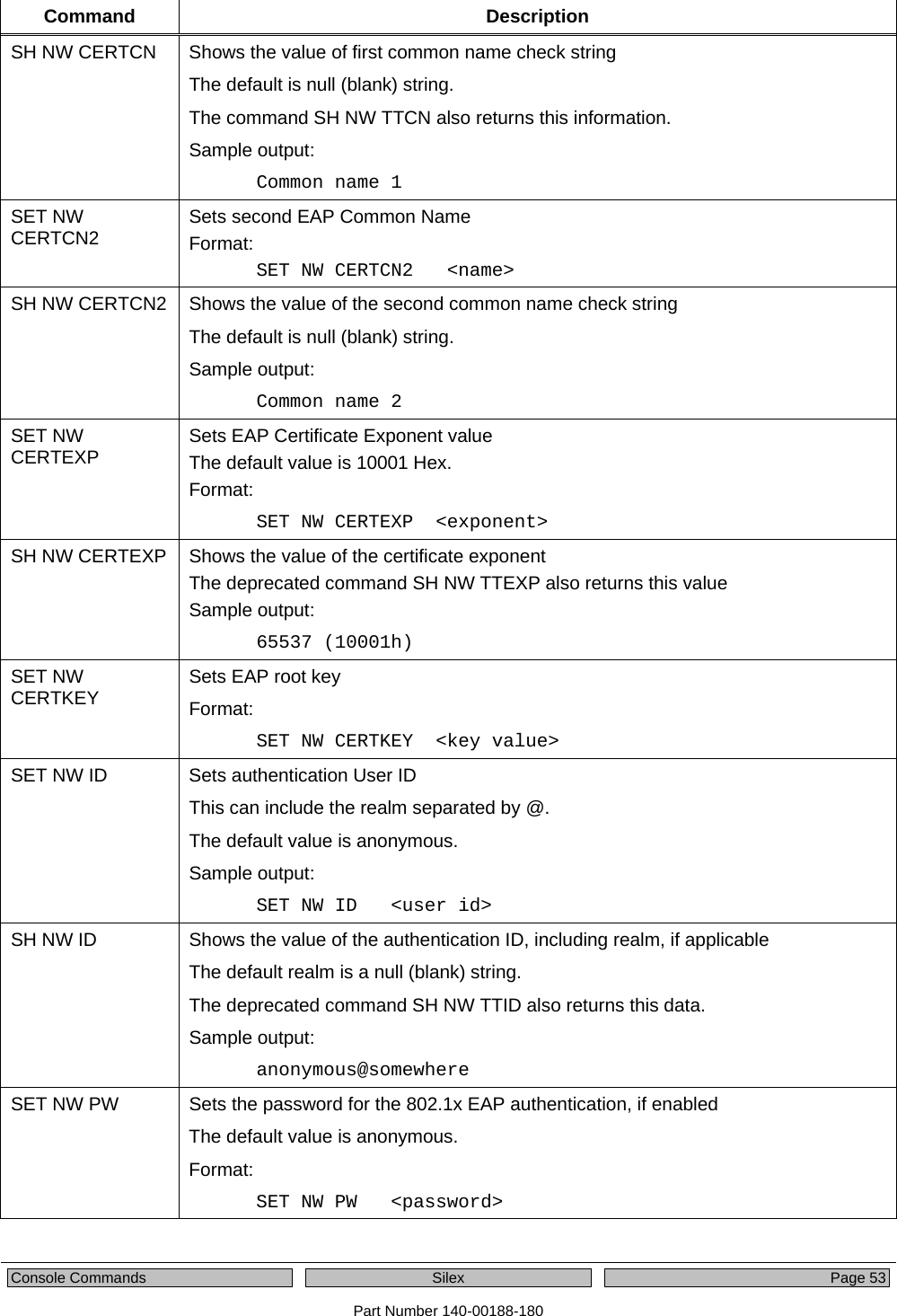
![Page 50 Silex Console Commands Part Number 140-00188-180 Command Description SET NW AUTHtype Sets wireless authentication type The default value is Open System Format: SET NW AUTHtype [OPEN | SHARED | TTLS | LEAP | PEAP | TLS | FAST | WPA-PSK ] SH NW AUTH Shows wireless authentication type Sample output: Authentication type= OPEN SYSTEM SET NW ETHAUTH Sets Ethernet wired authentication type The default value is Open System Format: SET NW ETHAUTH [TTLS | TLS | PEAP ] SH NW ETHAUTH Shows Ethernet wired authentication type Sample output: Authentication type= PEAP SET NW AUTHTRY Sets number of times the Serial Device Server will attempt to authentication The default value is 0. Format: SET NW AUTHTRY n SH NW AUTHTRY Shows number of authentication tries. Sample output: Authentication Try Count = 3 SET NW CHannel Sets WLAN ad-hoc channel number The valid numbers are 1 through 11. Format: SET NW CHannel n SET NW ENC Sets WLAN Encryption Mode. Supported modes are None, 64 bit WEP, 128 bit WEP, WPA, WPA2, WPA2-WPA The default value is Disable. Format: SET NW ENC [Disable | 64 | 128 | WPA | WPA2 ] SH NW ENC Shows the wireless encryption mode The deprecated command SH NW WEP also displays this information. Sample output: WiFi encryption is Disabled](https://usermanual.wiki/Silex-Technology/SX510.Users-Manual/User-Guide-1053777-Page-56.png)
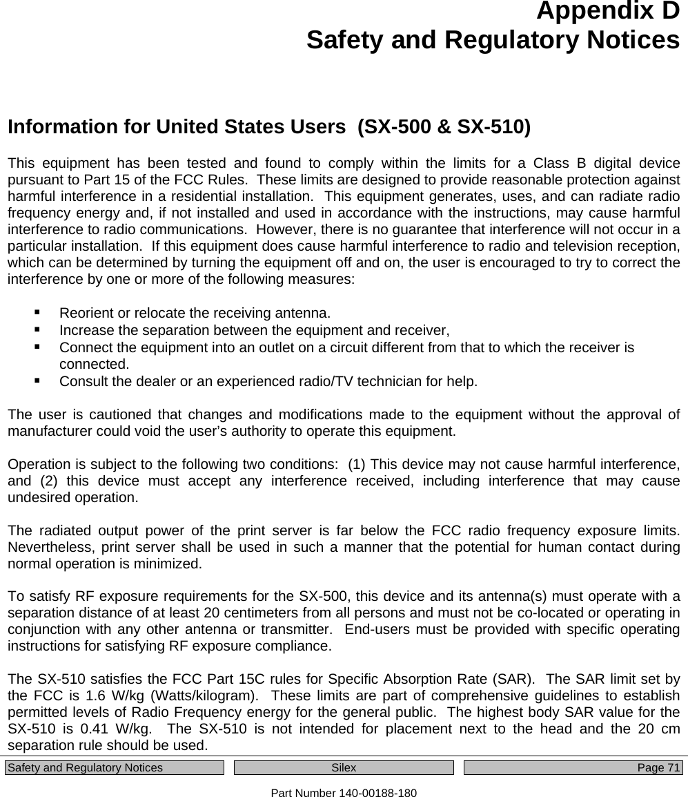
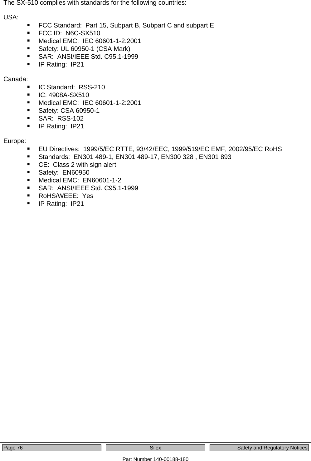
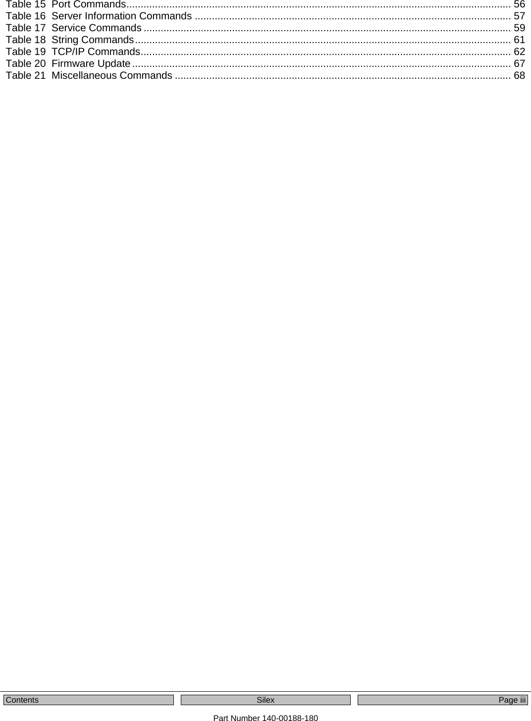
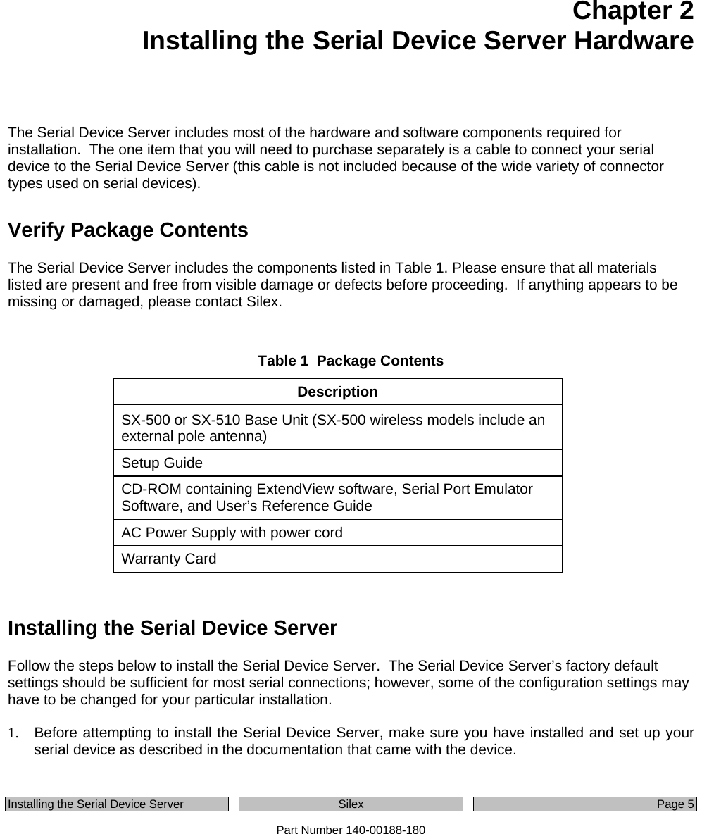
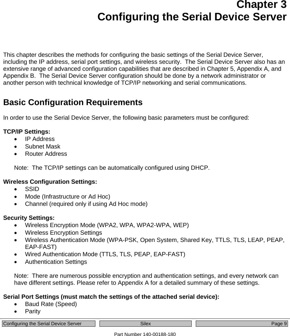
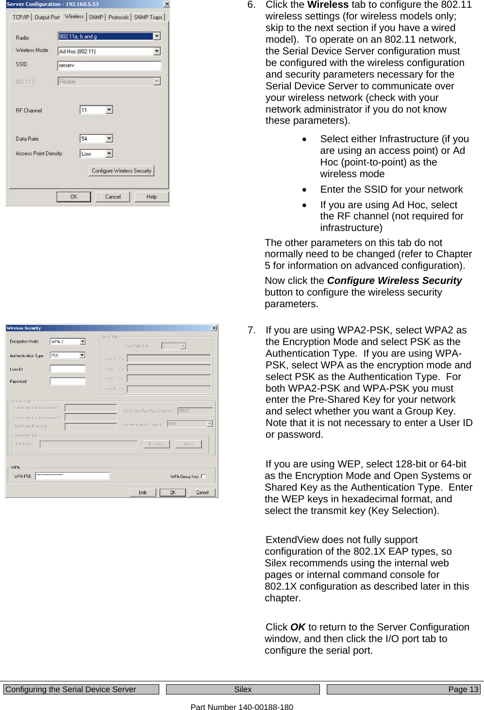
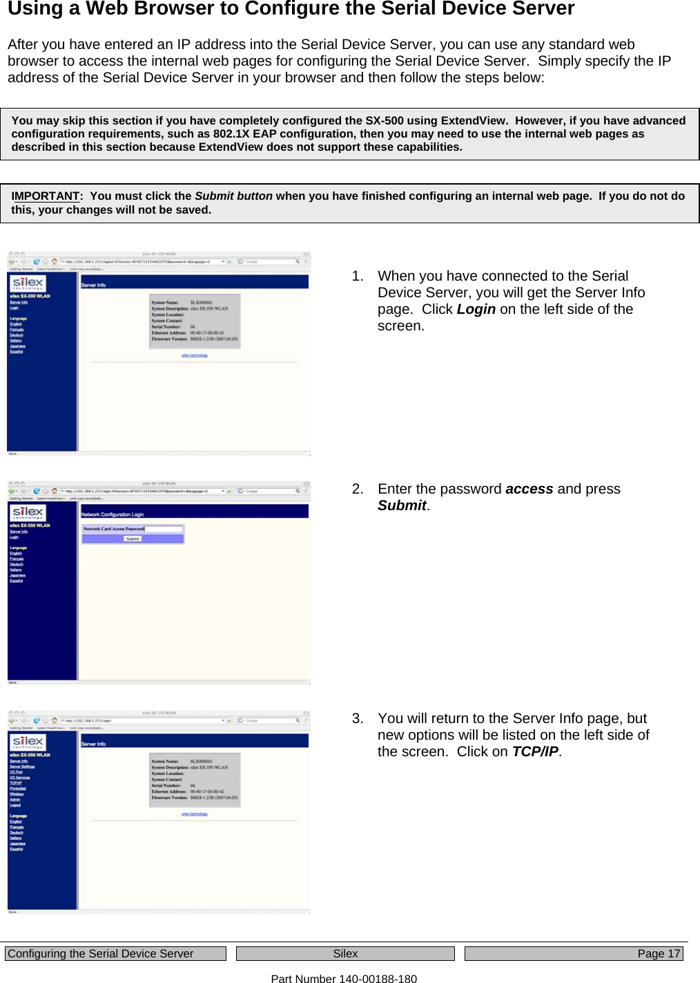
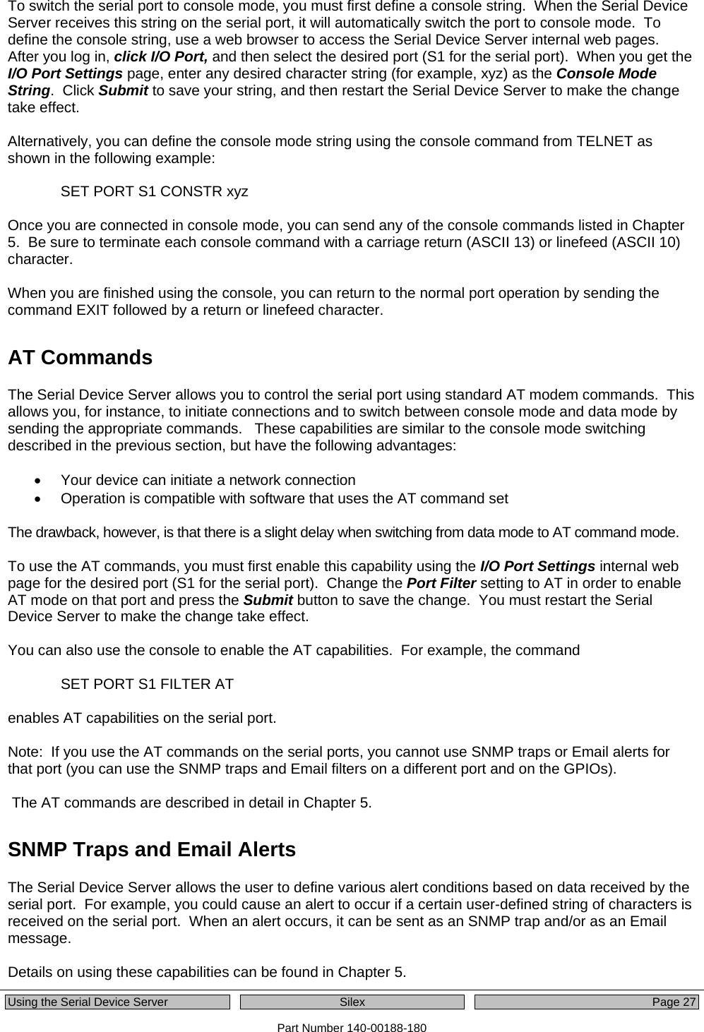
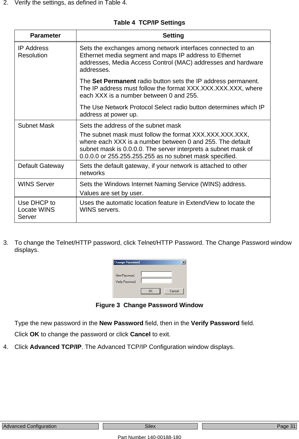
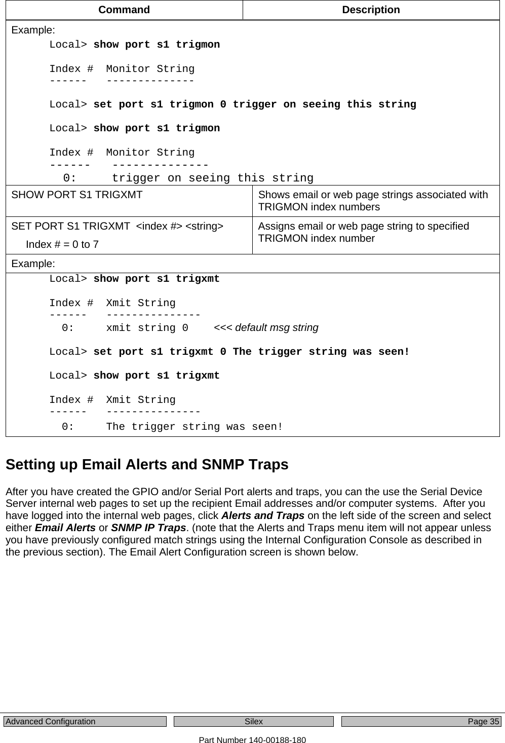
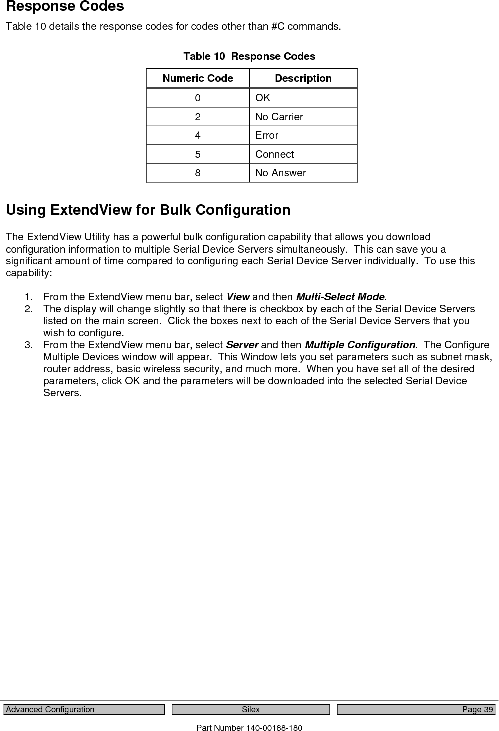
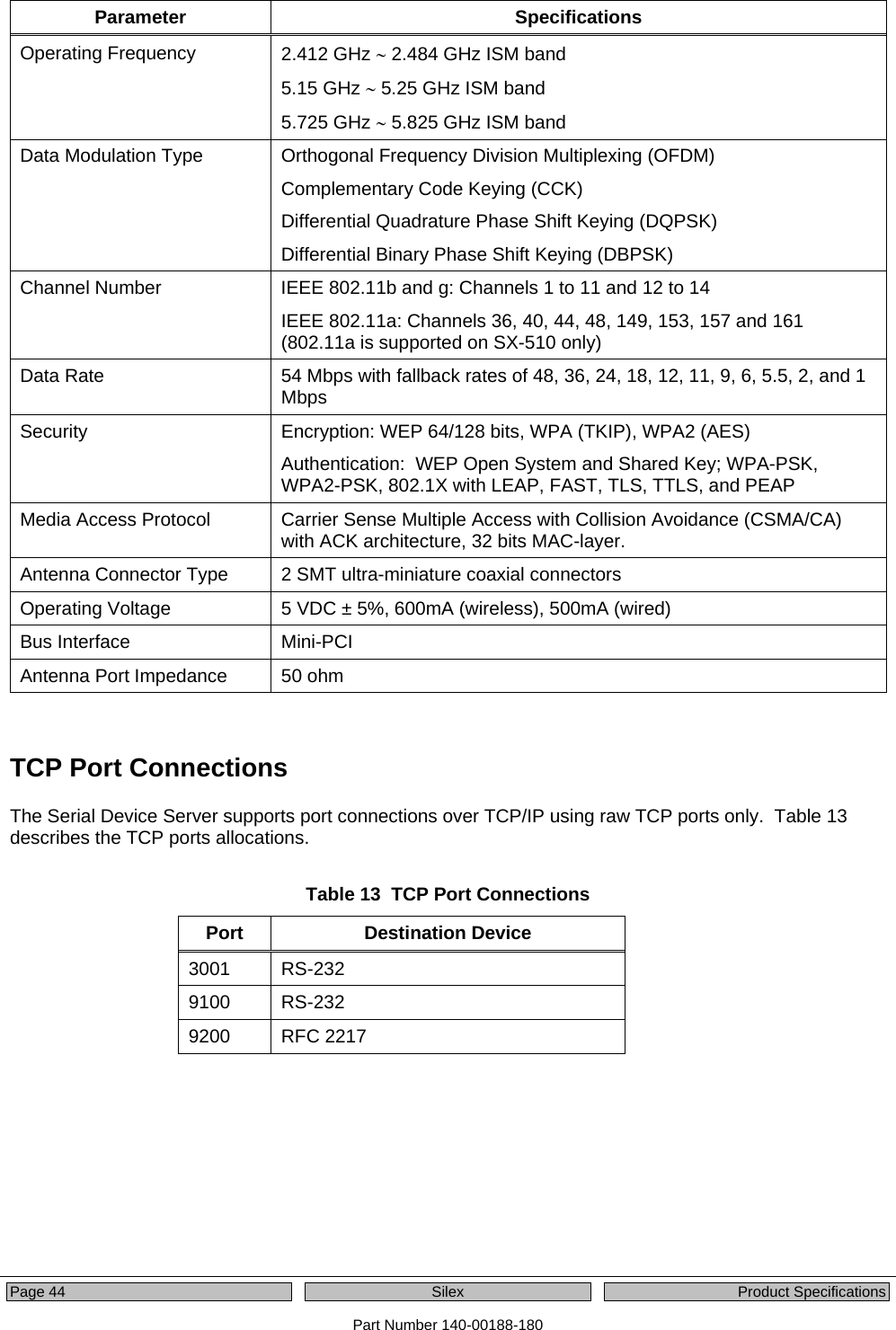
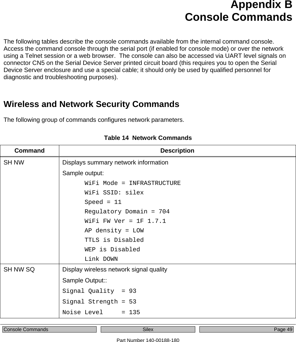
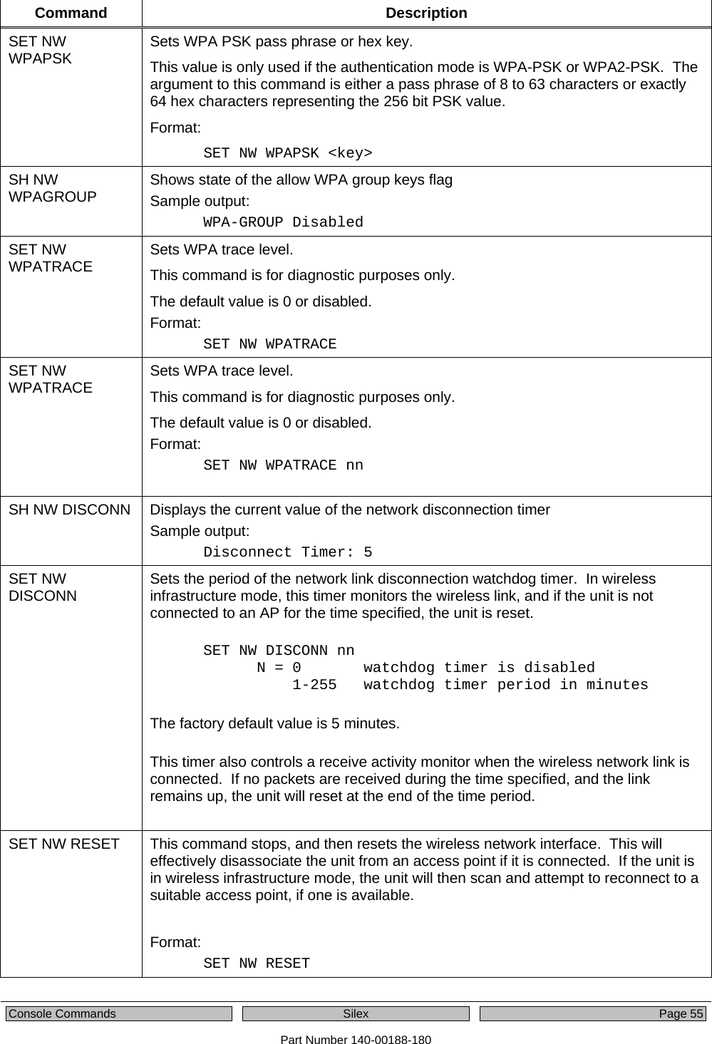
![Page 54 Silex Console Commands Part Number 140-00188-180 Command Description SET NW INAP Sets EAP inner-authentication protocol The possible protocols are PAP and MSCHAP_V2; the default value is PAP. Format: SET NW INAP [PAP|MSCHAP_V2] SH NW INAP Shows the inner authentication mode The deprecated command SH NW TTAP also returns this data. Sample output: Authentication protocol = PAP SET NW REALM Sets the realm portion of the 802.1x EAP authentication ID This value can also be set with the ID command. The default value is null. Format: SET NW REALM <realm> SH NW REALM Shows the realm associated with the authentication ID, if applicable. The default value is null (blank) string. The deprecated command SH NW TTRE also returns this data. Sample output: Somewhere SET NW WPAGROUP Enable or disable WPA group key mode. If enabled, group keys can be used for data link encryption. The default value is disabled. Sample output: SET NW WPAGROUP [ENABLE | DISABLE] SH NW WPAAUTO Shows state of WPA auto connect flag Sample output: WPA-AUTO Enabled SH NW WPAGROUP Shows state of the allow WPA group keys flag Sample output: WPA-GROUP Disabled. SET NW WPAGROUP Enable or disable WPA group key mode. If enabled, group keys can be used for data link encryption. The default value is disabled. Format: SET NW WPAGROUP [ENABLE | DISABLE]](https://usermanual.wiki/Silex-Technology/SX510.Users-Manual/User-Guide-1053777-Page-60.png)
![Page 56 Silex Console Commands Part Number 140-00188-180 Port Commands Table 15 Port Commands Command Description SH PORT Shows port parameters Sample output: Port Q-Size Type Attributes *S1 0 serial 115200 N 8 1 XON/XOFF CLEAR PORT S1 JOB Aborts the active job on the port. If the remote host is connected, additional data received will be discarded. Format: CL PORT S1 JOB SET PORT S1 FLOW Sets serial port flow control to NONE, XON/XOFF, CTS, or DSR The default value is none. Format: SET PORT S1 FLOW <flow> SET PORT S1 PARITY Sets serial port parity to NONE, EVEN, ODD, MARK, or SPACE The default value is none. Format: SET PORT S1 Parity <parity> SET PORT S1 SIZE Sets data bits on the serial port The default value is 8. Format: SET PORT S1 SIZE [7 | 8] SET PORT S1 SPEED Sets serial port baud rate. Options for BAUD are 300, 600, 1200, 2400, 7200, 9600, 19200, 38400, 57600, 115200, 230400, 460800, 921600 The default value is 115200. Format: SET PORT S1 SPEED <baudrate> SET PORT S1 STOP Sets serial port stop bits per character The default value is 1. Format: SET PORT S1 STOP [1 | 2] SET PORT S1 MODE Sets serial port line mode The default value is 232. Format: SET PORT S1 STOP [232 | 422 | 485 | 485D]](https://usermanual.wiki/Silex-Technology/SX510.Users-Manual/User-Guide-1053777-Page-62.png)
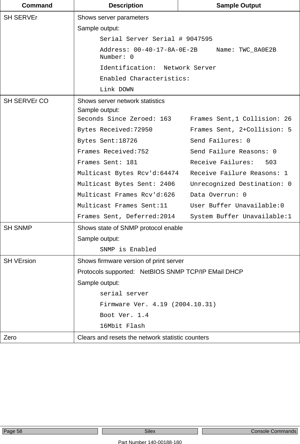
![Console Commands Silex Page 57 Part Number 140-00188-180 Server Information Commands Table 16 Server Information Commands Command Description Sample Output SET SERVEr Description Sets server description string Format: SET SERVEr DEscription <description-string> SET SERVEr NAme Sets server node name The default value is TWC_xxxxxx, where xxxxxx are the last 6 hex digits of the MAC address. Format: SET SERVEr NAme <name> SET SNMP GETCOMM Gets community name The default value is public. Format: SET SNMP GETCOMM <string> SET SNMP JETADmin Enables or disables JetAdmin compatibility The default value is enabled. Format: SET SNMP JETADmin [ ENable | DIsable] SET SNMP SETCOMM1 Sets community 1 name The default value is internal? Format: SET SNMP SETCOMM1 <string> SET SNMP SETCOMM2 Sets community 2 name The default value is Pass. Format: SET SNMP SETCOMM2 <string> SET SNMP CONtact Sets system contact string The default value is null. Format: SET SNMP CONtact <string> SET SNMP LOCation Sets system location string The default value is null. Format: SET SNMP LOCation <string> SH SERIAL Displays serial number of the unit Sample output: Serial number is 9047595](https://usermanual.wiki/Silex-Technology/SX510.Users-Manual/User-Guide-1053777-Page-63.png)
![Console Commands Silex Page 59 Part Number 140-00188-180 Service Commands Table 17 Service Commands Command Description SET SERVI <service name> BOT Sets beginning of transmission (BOT) string index for service The SH SERVI STRings command displays the available strings and their associated number; the default value is 1. Format: SET SERVI <service name> BOT nn SET SERVI <service name> EOT Sets end of transmission (EOT) string index for service The SH SERVI STRings command displays the available strings and their associated number; the default value is 1. Format: SET SERVI <service name> EOT nn SH SERVI STRings [string_num] Displays the BOT and EOT strings used in services If string_num is provided, then the specific string definition and expansion display. If string_num is not provided, then all string definitions display without their expansions. Sample Output: 10: \FF\04\FF\05\FF\06\FF\08 SET SERVI <service name> FIlter Sets filter index for service Format: SET SERVI <service name> FIlter nn Shows filter settings Sample output: SH SERVI FILters # Service Name Filter 1 TWC_FFFFFF 0: No Filter 2 BINARY_P1 0: No Filter 3 TEXT_P1 1: Text Substitution m= LF, r= CRLF 4 TWC_FFFFFF_P1_4 0: No Filter 5 TWC_FFFFFF_P1_5 0: No Filter 6 TWC_FFFFFF_P1_AT 4: PostScript Tagged Binary](https://usermanual.wiki/Silex-Technology/SX510.Users-Manual/User-Guide-1053777-Page-65.png)
![Page 60 Silex Console Commands Part Number 140-00188-180 Command Description SET SERVI <service name> FMS Sets filter 1 text replacement match string index. If the index is zero, the default string of <LF> (line feed) is used. The default value is 0. Format: SET SERVI <service name> FRM nn SET SERVI <service name> FRS Sets filter 1 text replacement replace string index. If the index is zero, the default string of <CRLF> (carriage return-line feed) is used. The default value is 0. Format: SET SERVI <service name> FRS nn SET SERVI <service name> IP Enables or disables IP based jobs such as lpd, raw tcp and ftp, on the service The default value is enabled for service 1 and 2, disabled for all others. Format: SET SERVI <service name> IP [ENable | DIsable] SET SERVI <service name> NAme Changes service name The default value varies by service Format: SET SERVI <service name> NAme <newname> SET SERVI <service name> POrt Sets output port associated with a service The default value is S1. Format: SET SERVI <service name> POrt <portname> SET SERVI <service name> PRIority Sets priority for service for multiple service transmissions simultaneously The default value is 10. Format: SET SERVI <service name> PRIority nn SH SERVI PRI [service_num] Shows priority of service. If service_num is not provided, the priority of all services is listed. SET SERVI <service name> RECeive Sets receive only mode for a service This option is required only for host applications that do not operate properly if data is received from the serial device. The default value is disabled. Sample output: SET SERVI <service name> RECeive [ENable | DIsable]](https://usermanual.wiki/Silex-Technology/SX510.Users-Manual/User-Guide-1053777-Page-66.png)
![Console Commands Silex Page 61 Part Number 140-00188-180 Command Description SET SERVI <service name> TCP Sets raw TCP port for service If port number is 0, raw TCP is disabled on service. The default value is 9100 for service 1, 3001 for service 2. Format: SET SERVI <service name> TCP nn SH SERVI SUMmary [service_num] Shows the basic parameters for a specific service. If service_num is not provided, parameters for all services are displayed. The command SH SERVI displays the same data as SHOW SERVI SUM. String Commands Table 18 String Commands Command Description SET STRing Set service string table entry String 1 to11 cannot be set or changed. Format: SET STRing <string #> ”value” CL STRing Clears the service string table entry Format: CL STRing <string #>](https://usermanual.wiki/Silex-Technology/SX510.Users-Manual/User-Guide-1053777-Page-67.png)
![Page 62 Silex Console Commands Part Number 140-00188-180 Command Description SH STRing [string_num] Defines the BOT and EOT strings used in services If string_num is provided, then the specific string definition and expansion are displayed. If string_num is not provided, then all string definitions are displayed without their expansions. Sample output: 1: 2: \1BE 3: \04 4: \1B%-12345X 5: @PJL 6: ENTER LANGUAGE= 7: PCL\0A 8: POSTSCRIPT\0A 9: \FF\04\FF\05\FF\06\FF\07 10: \FF\04\FF\05\FF\06\FF\08 11: \0C SH FILters Shows the filters that can modify a job stream Sample output: # Filter 0 No Filter 1 Text Substitution 2 AppleTalk 3 Text to PostScript 4 PostScript Tagged Binary 5 DC1 Special TCP/IP Commands Table 19 TCP/IP Commands Command Description SET IP ACcess Allows or prevents access to a block of remote addresses The default value is empty list. Format: SET IP ACcess [EN | DI | ALL] aa.bb.cc.dd {MAsk ee.ff.gg.hh]](https://usermanual.wiki/Silex-Technology/SX510.Users-Manual/User-Guide-1053777-Page-68.png)
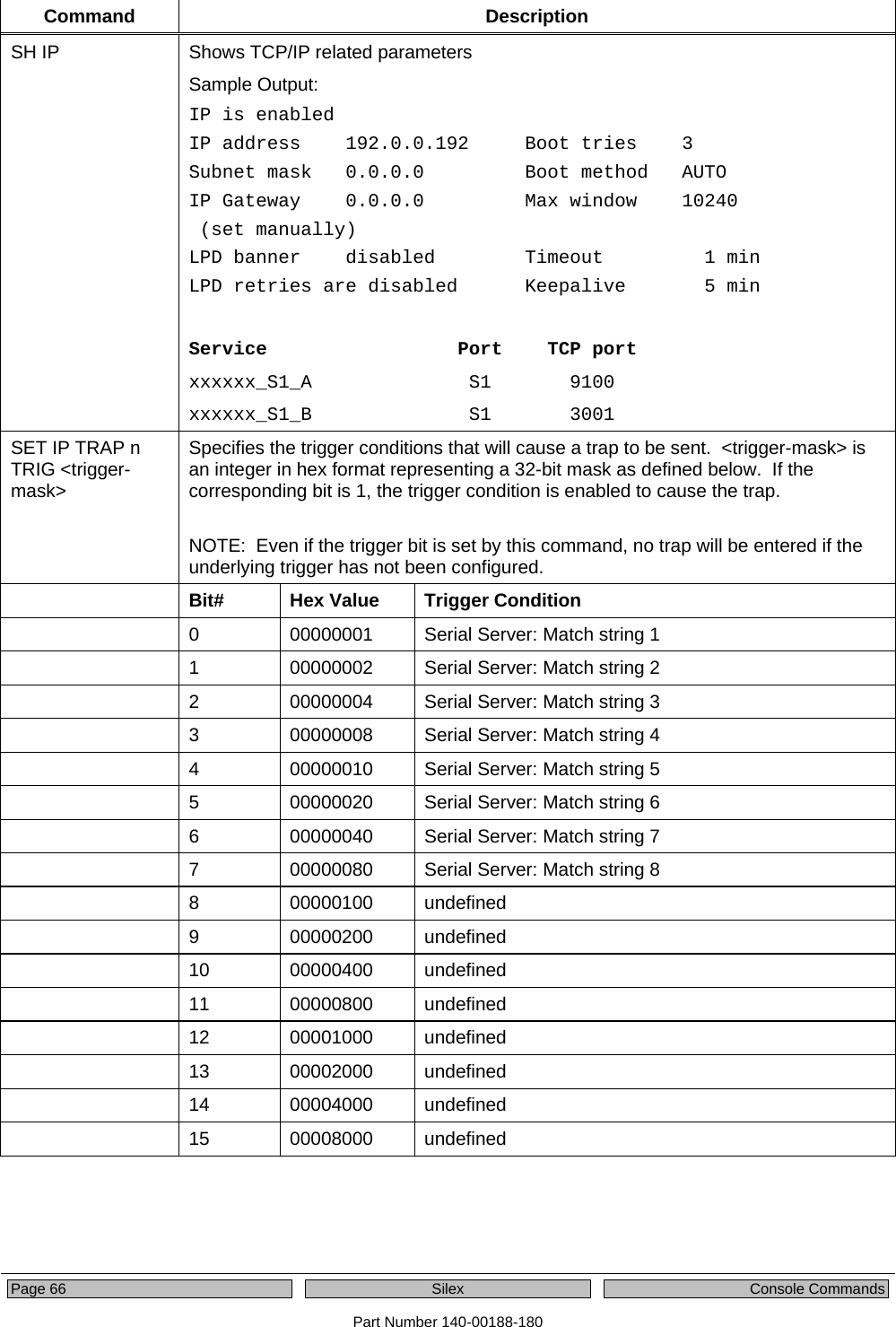
![Console Commands Silex Page 63 Part Number 140-00188-180 Command Description SET IP RANge Allows or prevents access to a range of remote addresses The default value is empty list. Format: SET IP RANge [EN | DI | ALL] aa.bb.cc.dd {MAx ee.ff.gg.hh] SH IP ACcess Displays current access list settings Sample output: All hosts permitted access SET IP ADdress Sets server IP address The default value is 192.0.0.192 Format: SET IP ADdress aa.bb.cc.dd SET IP ARP ENable Enables or disables setting of IP address with an ARP packet The default value is Enable. Format: SET ARP [ENable | DIsable] SET IP BAnner Enables or disables printing of job banner on LPD jobs The default value is Disable. Format: SET IP BAnner [ENable | DIsable] SET IP CHKSUM Enables or disables verification of IP checksum on received packets The default value is Enable. Format: SET IP CHKSUM [ENable | DIsable] SET IP BOot Sets number of tries for each enabled IP boot method, if not set to static The default value is 3. Format: SET IP BOot n SET IP ENable Enables or disables all IP based protocols The value is Enable. Format: SET IP [ENable | DIsable] SET IP FTIme Sets IP timeout If enabled, the IP timeout is measured in seconds. If disable, the IP timeout is in minutes. The default value is Disable. Format: SET IP FTIme [ENable | DIsable]](https://usermanual.wiki/Silex-Technology/SX510.Users-Manual/User-Guide-1053777-Page-69.png)
![Page 64 Silex Console Commands Part Number 140-00188-180 Command Description SET IP FTP Enables or disables FTP protocol The default value is Enable. Format: SET IP FTP [ENable | DIsable] SET IP HTTP Enables or disables HTTP protocol The default value is Enable. Format: SET IP HTTP [ENable | DIsable] SET IP KEepalive Sets interval in minutes for sending TCP keepalive packets on a connection The default value is 5 minutes. Format: SET IP KEepalive n SET IP LPD Enables or disables the LPD protocol The default value is Enable. Format: SET IP LPD [ENable | DIsable] SET IP MEthod Sets method of getting IP address The default value is Auto. Format: SET IP MEthod [ AUTO | BOOTP | RARP | DHCP | STATIC ]SET IP PIng Sends IP ping packets to test connection to remote host Format: SET IP PIng aa.bb.cc.dd SET IP PRObe Enables or disables TCP connection probes The default value is Disable. Format: SET IP PRObe [ENable | DIsable] SET IP RARp Enables setting of default router and/or subnet mask based on RARP IP address set The default value is 0. Format: SET IP RARp nn nn: 0=both 1=no subnet, 2=no router, 3=neither SET IP REtry Enables or disables LPD retry on incomplete job The default value is Disable. Format: SET IP REtry [ENable | DIsable]](https://usermanual.wiki/Silex-Technology/SX510.Users-Manual/User-Guide-1053777-Page-70.png)
![Console Commands Silex Page 65 Part Number 140-00188-180 Command Description SET IP ROuter Sets default router address The default value is 0.0.0.0. Format: SET IP ROuter aa.bb.cc.dd SET IP SUbnet Sets IP subnet mask The default value is 0.0.0.0. Format: SET IP SUbnet aa.bb.cc.dd SET IP TCP Enables or disables the raw TCP 9100 protocol The default value is Enable. Format: SET IP TCP [ENable | DIsable] SET IP TELnet Enables or disables Telnet protocol The default value is Enable. Format: SET IP TELnet [ENable | DIsable] SET IP TFTP Enables or disables TFTP protocol The default value is Enable. Format: SET IP TFTP [ENable | DIsable ] SET IP TImeout Sets TCP inactivity timeout. If fast timeout is enabled, the timeout is calculated as seconds. If fast timeout is disabled, the timeout is calculated as minutes. The default value is 1 minute. Format: SET IP Timeout n SET IP WIndow Sets TCP maximum window size in bytes The default value is 10240. Format: SET IP WIndow nn](https://usermanual.wiki/Silex-Technology/SX510.Users-Manual/User-Guide-1053777-Page-71.png)
![Console Commands Silex Page 67 Part Number 140-00188-180 Firmware Update Table 20 Firmware Update Command Description SET LOAd ENable Sets the firmware to perform a soft reset and enter the server boot program after the next Exit command. This command is used for diagnostic purposes only. The default value is Disable. Format: SET LOAd (ENable | DIsable ] SET LOAd HOst Sets the node name of the Netware boot host. This command is used for diagnostic purposes only. The default value is null>\ Format: SET LOAd HOst <name> SET LOAd IP Sets source computer IP address for TFTP get operation. The default value is 0.0.0.0. Format: SET LOAd IP aa.bb.cc.dd SET LOAd SOftware Sets filename on host for TFTP get update Format: SET LOAd SOftware <filename> SET LOAd TFTP Initiates firmware update using TFTP get operation. The TFTP server address must be set using SET LOAd IP and the filename using SET LOAd SOftware. The server will reset after the firmware update is completed. Format: SET LOAd TFTP SET LOAd XModem Initiates firmware update using the XModem protocol on the serial console The server will reset after the firmware update is completed. Format: SET LOAd XModem SH LOAd Shows the firmware update parameters Sample output: Firmware load is disabled Load Host IP = 0.0.0.0 Software file = xxxx.bin Load Host Name =](https://usermanual.wiki/Silex-Technology/SX510.Users-Manual/User-Guide-1053777-Page-73.png)