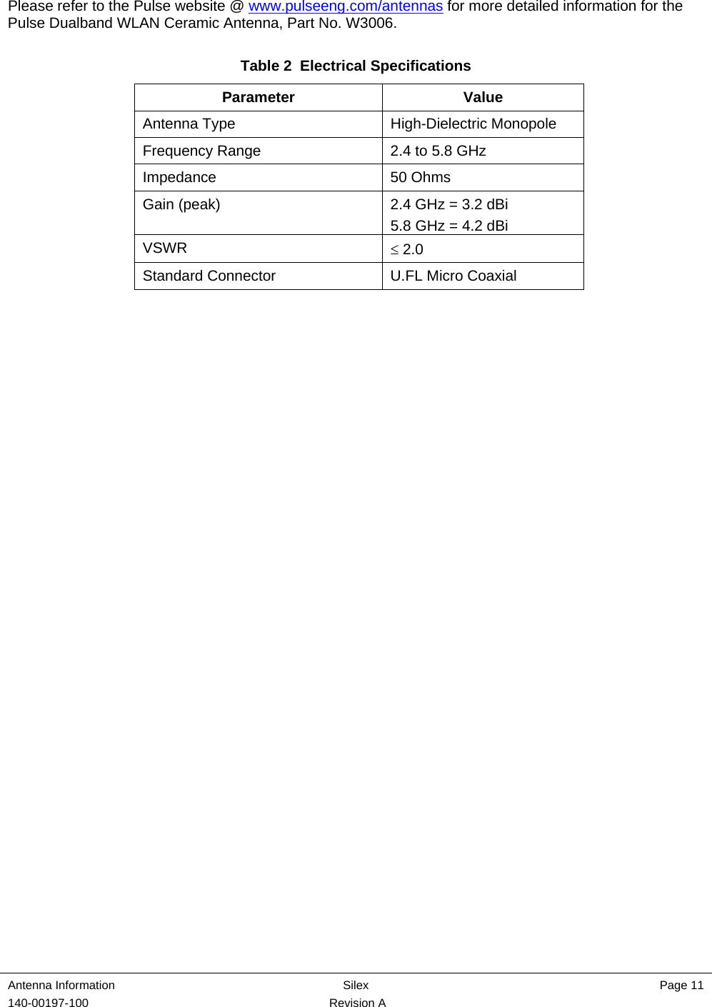
Silex Technology SXSDCAG Wireless 802.11a/b/g SD Card Radio User Manual

Silex Technology, Inc. Wireless 802.11a/b/g SD Card Radio Users Manual

Users Manual

              SX-SDCAG 802.11a/b/g SDIO Module User Manual 140-00197-100 Rev A
 140-00197-100  Revision A    © 2010 Silex Technology America, Inc. All rights reserved. February 2010  Silex Technology America SPECIFICALLY DISCLAIMS THE IMPLIED WARRANTIES OF MERCHANTABILITY AND FITNESS OF THIS PRODUCT FOR A PARTICULAR PURPOSE.  Silex shall not be liable for any errors contained in this manual or for any damages resulting from loss of use, data, profits, or any incidental or consequential damages arising from the use of SILEX products or services.  The information contained in this documentation is subject to change without notice.  Information and descriptions contained herein are the property of Silex.  Such information and descriptions may not be copied, disseminated, or distributed without the express written consent of Silex.  This publication is subject to change without notice.   Trademarks ExtendView is a trademark of Silex Technology America, Inc.  All other company or product names referenced  in this document may be trademarks or registered trademarks of their respective owners.     Silex Technology America, Inc. www.silexamerica.com
 Contents Silex  Page 1 140-00197-100  Revision A Contents  About This User Manual ............................................................................................................................................ 2 Safety Precautions................................................................................................................................................. 2 Emissions Disclaimer............................................................................................................................................. 2 Chapter 1: Introduction .............................................................................................................................................. 3 Chapter 2 Hardware Specifications/Compliance....................................................................................................... 4 FCC Information..................................................................................................................................................... 4 Information for Canadian Users (IC Notice)........................................................................................................... 5 Specifications......................................................................................................................................................... 7 Chapter 3 Installation................................................................................................................................................. 8 Installation Requirements ...................................................................................................................................... 8 Installation Procedure ............................................................................................................................................ 8 Appendix A Antenna Information............................................................................................................................. 10 Antenna Specifications ........................................................................................................................................ 10 Appendix B Silex Contact Information..................................................................................................................... 12
 Page 2   Silex  About This User Guide 140-00197-100  Revision A About This User Manual This user manual provides detailed specifications, diagrams and additional information required to install the SX-SDCAG 802.11a/b/g SDIO module into a product. The intended audiences are the developers and engineers responsible for the integration of the module in another product.  Safety Precautions  To prevent damage to the SX-SDCAG module’s electronic circuit components, follow established ESD practices and procedures for handling static-sensitive devices.  All ESD-sensitive components must be stored and shipped in ESD-conductive bags or bubble-wrap and labeled as such using the standardized ESD adhesive warning label.  Ethernet electrical wiring must be at least 6 feet from bare power wiring or lightning rods and associated wires, and at least 6 inches from other types of wire (antenna wires, doorbell wires, wires from transformers to neon signs), steam or hot water pipes, and heating devices.  Protectors and grounding wire placed by the service provider must not be connected to, removed, or modified by the customer. Emissions Disclaimer Final emission certification per FCC, IC, CE and other agency requirements are the responsibility of the OEM (refer to chapter 2 for additional information).
 Introduction Silex  Page 3 140-00197-100 Revision A   Chapter 1: Introduction The SX-SDCAG is an 802.11a/b/g radio/baseband module in a standard SDIO form factor. Designed for wireless local area network (WLAN) applications that require low power consumption, the SX-SDCAG is ideal for battery-operated portable devices in the medical, weights and measures, transportation and other industries.  SX-SDCAG features include:  •  Highly Integrated System for 802.11a/b/g WLAN  •  U.FL antenna connectors with diversity support •  Wide operating temperature range •  Integrated Atheros AR6002XZ Single Chip  •  Integrated high performance Dual-Band Front End Module (FEM), Band Pass Filter, 26MHz Crystal •  16Kbit EEPROM  •  Advanced power management to minimize standby and active power  •  WEP 64/128, WPA (TKIP), WPA2 (802.11i) security  •  Linux, Windows CE, and Windows Mobile drivers available from Silex (porting will be required in most cases)                                               Figure 1  SX-SDCAG Dimensions (mm)  24.0  1.5 46.0 4.1 27.1
 Introduction Silex  Page 4 140-00197-100 Revision A  Chapter 2 Hardware Specifications/Compliance  FCC Information FCC ID: N6C-SXSDCAG  NOTICE  In accordance with FCC Part 15, the SX-SDCAG is listed as a Modular Transmitter device. End products that include the SX-SDCAG shall have the words “Contains Transmitter module FCC ID: N6C-SXSDCAG” on an exterior label.   This equipment complies with Part 15 of the FCC Rules. Operation is subject to the following two conditions: (1) this device may not cause harmful interference, and (2) this device must accept any interference received, including interference that may cause undesired operation.  This equipment has been tested and found to comply within the limits for a Class B digital device, pursuant to part 15 of the FCC Rules. These limits are designed to provide reasonable protection against harmful interference in a residential installation.  This equipment generates, uses, and can radiate radio frequency energy and, if not installed and used in accordance with the instructions, may cause harmful interference to radio communications.  However, there is no guarantee that interference will not occur in a particular installation. If this equipment does cause harmful interference to radio or television reception, which can be determined by turning the equipment off and on, the user is encouraged to try to correct the interference by one or more of the following measures:  •  Reorient or relocate the receiving antenna •  Increase the separation between the equipment and receiver •  Connect the equipment into an outlet on a different circuit from that to which the receiver is connected •  Consult the dealer or an experienced radio/TV technician for help.  The transmitter must not be co-located or operated in conjunction with any other antenna or transmitter.  In accordance with 15.407(e), within the 5.15 – 5.25 GHz band, this device must be restricted to indoor use to reduce any potential for harmful interference to co-channel Mobile Satellite Systems.
 Specifications/Compliance Silex  Page 5 140-00197-100 Revision A   The available scientific evidence does not show that any health problems are associated with using low power wireless devices.  There is no proof, however, that these low power wireless devices are absolutely safe.  Low power wireless devices emit low levels of radio frequency energy (RF) in the microwave range while being used. Whereas high levels of RF can produce health effects (by heating tissue), exposure to low-level RF that does not produce heating effects causes no known adverse health effects.  Many studies of low-level RF exposures have not found any biological effects. Some studies have suggested that some biological effects might occur, but such findings have not been confirmed by additional research.  To satisfy RF exposure requirements, this device and its antenna(s) must operate with a separation distance of at least 20 centimeters from all persons and must not be co-located or operated in conjunction with any other antenna or transmitter.  End-users must be provided with specific operating instructions for satisfying RF exposure.  FCC WARNING:  Changes or modifications not expressly approved by the party responsible for compliance could void the user’s authority to operate the equipment.  Information for Canadian Users (IC Notice) The term “IC” before the radio certification number only signifies that Industry Canada technical specifications were met. Operation is subject to the following two conditions: (1) this device may not cause interference, and (2) this device must accept any interference, including interference that may cause undesired operation of the device.  This Class B digital apparatus meets all requirements of the Canadian Interference-Causing Regulations. I. The device for the band 5150-5250MHz is for indoor usage to reduce potential for harmful interference to co-channel Mobile Satellite systems. II. The maximum antenna gain permitted (for devices in the bands 5250-5350 MHz and 5470-5725 MHz) to comply with the e.i.r.p. limit III.  The maximum antenna gain permitted (for devices in the band 5725-5825 MHz) to comply with the e.i.r.p. limits specified for point-to-point and non point-to-point operation as appropriate, as stated in section A9.2(3). Users should be cautioned to take note that high-power radars are allocated as primary users (meaning they have priority) of the bands 5250-5350 MHz and 5650-5850 MHz and these radars could cause interference and/or damage to LE-LAN devices.  To prevent radio interference to the licensed service, this device is intended to be operated indoors and away from windows to provide maximum shielding. Equipment that is installed outdoors is subject to licensing.  This device has been designed to operate with the antennas listed below, and having a maximum gain of 3.2dB @ 2.4 GHz and 4.2 dB @ 5 GHz. Antennas not included in this list or having a higher gain are strictly prohibited for use with this device. The required antenna impedance is 50 ohms. •  Ethertronics Prestta WLAN Embedded Antenna, Part No. 1000418 •  Pulse Engineering Dualband WLAN Ceramic Chip Antenna, Part No. W3006  To reduce potential radio interference to others, the antenna type and its gain should be so chosen that the equivalent isotropically radiated power (EIRP) is not more than required for successful communication.  The available scientific evidence does not show that any health problems are associated with using low power wireless devices.  There is no proof, however, that these low power wireless devices are absolutely
 Page 6  Silex  Specifications/Compliance 140-00197-100 Revision A safe.  Low power wireless devices emit low levels of radio frequency energy (RF) in the microwave range while being used. Whereas high levels of RF can produce health effects (by heating tissue), exposure to low-level RF that does not produce heating effects causes no known adverse health effects.  Many studies of low-level RF exposures have not found any biological effects. Some studies have suggested that some biological effects might occur, but such findings have not been confirmed by additional research.
 Specifications/Compliance Silex  Page 7 140-00197-100 Revision A   Specifications Operating environment:  Temperature: -20º to +70ºC (-4º to +158ºF)   Humidity: 20% to 80% Storage environment:  Temperature: -30º to +85ºC (-22º to +185ºF)   Humidity: 20% to 85% Supply voltage:  3.3V ± 5% Host interface:  SDIO IEEE 802.11b  Frequency: 2412MHz-2462MHz   Transmission system:  DSSS   Transmission speed: 1/2/5/11Mbps  Automatic detection  Channel: 1-11 IEEE 802.11g  Frequency: 2412MHz-2462MHz   Transmission system:  OFDM  Transmission speed: 6/9/12/18/24/36/48/54Mbps  Automatic detection  Channel: 1-11  IEEE 802.11a  Frequency: 5180MHz-5240MHz, 5745-5825MHz   Transmission system:  OFDM  Transmission speed: 6/9/12/18/24/36/48/54Mbps  Automatic detection   Channel: 36-48, 149-165
 Installation Silex  Page 8 140-00197-100 Revision A Chapter 3 Installation Installation Requirements The SX-SDCAG must be installed in a device that contains a 9-pin SDIO slot.  The SX-SDCAG has FCC limited single modular approval, which can eliminate the need for you to obtain FCC Part 15 Subpart C and E (intentional radiation) approvals for your device. In order to use this FCC/IC limited single modular approval for the SX-SDCAG, OEM integrators must:  1.  include “Contains FCC ID: N6C-SXSDCAG, IC: 4908B-SXSDCAG” on the exterior label of your device. 2.  ensure for use in the United States and Canada that the driver for the SX-SDCAG in your product disables scanning on channels 12-14, 50-70 and 80-144 by loading a table with disabled channels into the SX-SDCAG during initialization. 3.  ensure the driver does not permit use of channels 12-14, 50-70 and 80-144 in ad-hoc mode in the United States and Canada by using the same disabling method. 4.  use an antenna referred to in appendix A or an equivalent type antenna with equal or lower gain. 5.  include all required statements in your final product user’s manual (per 15.21, 15.27, 15.105, 15.407(e), etc) and final product labeling (per 15.19).  Refer to FCC/IC Information in previous chapter. 6.  include following statement “In accordance with 15.407(e), within the 5.15 – 5.25 GHz band, this device must be restricted to indoor use to reduce any potential for harmful interference to co-channel Mobile Satellite Systems.” 7.  not provide Instructions on how to remove or install the SX-SDCAG to your end users. 8.  provide regulated +3.3 VDC +/- 5% power to the SX-SDCAG.  If you do not follow the above instructions, then it is your responsibility to obtain the necessary FCC approvals.  Installation Procedure To install the SX-SDCAG:  1.  Be sure to use the proper antistatic handling techniques.
 Specifications/Compliance Silex  Page 9 140-00197-100 Revision A   2.  Connect one end of the antenna cable to the main antenna connector on the SX-SDCAG (see figure 2). If you are using a diversity antenna configuration, connect one end of the second antenna cable to the secondary antenna on the SX-SDCAG.   Figure 2.  Connecting the Antenna(s) and cable(s) to the SX-SDCAG   3.  Insert the SX-SDCAG into an available SDIO slot in your device. Make sure that it is securely seated.  4.  If your device is subject to significant vibration or other forces, Silex recommends securing the SX-SDCAG using the corner mounting hole with a screw to prevent the accidental ejection of the card.       Figure 3.  Securing the SX-SDCAG M2 Screw
 Antenna Information  Silex    Page 10 140-00197-100 Revision A Appendix A Antenna Information Antenna Specifications Please refer to the Ethertronics website @ www.ethertronics.com for more detailed information for the Prestta WLAN Embedded Antenna, Part No. 1000418.  Table 1  Electrical Specifications Parameter Value Antenna Type  Isolated Magnetic Dipole Frequency Range  2.4 to 5.8 GHz Impedance 50 Ohms Gain (peak)  2.4 GHz = 2.5 dBi 5.8 GHz = 3.5 dBi VSWR  ≤ 2.0 Standard Connector  U.FL Micro Coaxial
 Antenna Information  Silex  Page 11 140-00197-100 Revision A   Please refer to the Pulse website @ www.pulseeng.com/antennas for more detailed information for the Pulse Dualband WLAN Ceramic Antenna, Part No. W3006.  Table 2  Electrical Specifications Parameter Value Antenna Type  High-Dielectric Monopole Frequency Range  2.4 to 5.8 GHz Impedance 50 Ohms Gain (peak)  2.4 GHz = 3.2 dBi 5.8 GHz = 4.2 dBi VSWR  ≤ 2.0 Standard Connector  U.FL Micro Coaxial
 Antenna Information  Silex    Page 12 140-00197-100 Revision A Appendix B Silex Contact Information  Silex Technology America, Inc. www.silexamerica.com Technical Support:  support@silexamerica.com Sales:  sales@silexamerica.com Tel:  (801) 748-1199  8:00 to 5:00 Mountain Time Tel:  (866) 765-8761 toll-free Fax: (801) 748-0730  Silex Technology Europe GmbH www.silexeurope.com Tel:  +49-2159-67500 Tel:  0800-7453938 German toll free Email:  contact@silexeurope.com  Silex Technology Beijing, Inc. www.silex.com.cn Tel:  +86-10-8497-1430 Email:  contact@silex.com.cn  Corporate Headquarters Silex Technology, Inc. www.silex.jp Tel:  +81-6-6730-3751 Email:  support@silex.jp Silex Technology America, Inc. www.silexamerica.com

Navigation menu