Silex Technology SXSP242 Low-Energy WiFi Dual-Band 802.11a/b/g/n User Manual User s Guide
Silex Technology, Inc. Low-Energy WiFi Dual-Band 802.11a/b/g/n User s Guide
Contents
- 1. Users Manual
- 2. 03 User Manual
Users Manual
Model name :
SX-SP242

Document Conventions
Text Conventions
bold Bold type within paragraph text indicates commands, file names,
directory names, paths, output, or returned values.
Example: The DK_Client package will not function unless you
use the wdreg_install batch file.
italic Within commands, italics indicate a variable that the user must
specify.
Example: mem_alloc size_in_bytes
Titles of manuals or other published documents are also set in
italics.
Courier The Courier font indicates output or display.
Example:
Error:Unable to allocate memory for transfer!
Menu The Menu character tag is used for menu items.
Example: Choose Edit > Copy.
[ ] Within commands, items enclosed in square brackets are optional
parameters or values that the user can choose to specify or omit.
{ } Within commands, items enclosed in braces are options from
which the user must choose.
| Within commands, the vertical bar separates options.
… An ellipsis indicates a repetition of the preceding parameter.
> The right angle bracket separates successive menu selections.
Example: Start > Programs > DK > wdreg_install.
Notices
NOTE: This message denotes neutral or positive information that calls out
important points to the text. A note provides information that may apply only
in special cases.

Introduction
The 802.11n Adapter supports 802.11n. The card uses the Client Utility (ACU) which is
a user-mode utility designed to edit and add profiles for selected network interface
adapters.
System Requirements
Laptop/ PC containing:
32-bit PCI Express Bus
32 MB memory or greater
300 MHz processor or higher
Microsoft Windows 2000, Windows Millennium Edition, Windows 98 Second
Edition, Windows XP, or Windows NT 4.0 (with Service Pack 6)
Profile Management
Configure the wireless network adapter (wireless card) from the Profile Management tab
of the Client Utility.
Add a profile
Edit a profile
Import a Profile
Export a Profile
Order profiles
Switch to a different profile
Remove a profile
Connect to a Different
Network
The wireless network adapter works in either infrastructure mode (which uses an access
point) or ad hoc mode (a group of stations participating in the wireless LAN).
Create or Modify a Configuration Profile
To add a new configuration profile, click New on the Profile Management tab. To modify
a configuration profile, select the configuration from the Profile list and click the Modify
button.
The Profile Management dialog box displays the General tab. In profile management:
Edit the General tab.
Edit the Security tab.
Edit the Advanced tab.
To configure a profile for ad hoc or access point (infrastructure) mode, edit the Network
Type field on the Advanced tab.
Note that the ACU only allows the creation of 16 configuration profiles. After the
creation of 16 profiles, clicking the New button displays an error message. Remove an
old profile or modify an existing profile for a new use.
Remove a Configuration Profile
1. Go to the Profile Management tab.
2. Select the profile to remove from the list of configuration profiles.
3. Click the Remove button.
Auto Profile Selection Management
Including a profile in the auto selection feature allows the wireless adapter to
automatically select that profile from the list of profiles and use it to connect to the
network.
Including a profile in auto profile selection:
1. On the Profile Management tab, click the Order Profiles button.
2. The Auto Profile Selection Management window appears, with a list of all created
profiles in the Available Profiles box.
3. Highlight the profiles to add to auto profile selection, then click Add. The profiles
appear in the Auto Selected Profiles box.
Ordering the auto selected profiles:
1. Highlight a profile in the Auto Selected Profiles box.
2. Click Move Up, Move Down, or Remove as appropriate. The first profile in the Auto
Selected Profiles box has highest priority, and the last profile has lowest priority.
3. Click OK.
4. Check the Auto Select Profiles box.
5. Save the modified configuration file.
When auto profile selection is enabled by checking Auto Select Profiles on the Profile
Management tab, the adapter scans for an available network. The profile with the
highest priority and the same SSID as one of the found networks is the one that is used
to connect to the network. If the connection fails, the adapter tries the next highest
priority profile that matches the SSID, and so on.
With auto profile selection enabled, the wireless adapter scans for available networks.
The highest priority profile with the same SSID as a found network is used to connect to
the network. On a failed connection, the adapter tries with the next highest priority
profile.
Switching to a Different Configuration Profile
1. To switch to a different profile, go to the Profile Management tab.
2. Click on the profile name in the Profile List.
3. Click the Activate button.
The Profile List provides icons that specify the operational state for that profile. The list
also provides icons that specify the signal strength for that profile.
Import and Export Profiles
Importing a Profile
1. From the Profile Management tab, click the Import button. The Import Profile
window appears.
2. Browse to the directory where the profile is located.
3. Highlight the profile name.
4. Click Open. The imported profile appears in the profiles list.
Exporting a Profile
1. From the Profile Management tab, highlight the profile to export.
2. Click the Export button. The Export Profile window appears.
3. Browse to the directory to export the profile to.
4. Click Save. The profile is exported to the specified location.
TCP/IP Configuration
Configuring the TCP/IP Address for the network device:
1. After configuring the wireless network adapter properties, open the Control Panel and
open Network and Dial-up Connections.
2. Find the Local Area Connection associated with the wireless network adapter. Right-
click that connection, and click Properties.
3. Select Internet Protocol (TCP/IP) and click Properties.
4. Click the radio button Use the following IP address, then enter an IP address and Subnet
mask. Assigning an IP address and Subnet mask allows stations to operate in access
point mode (infrastructure mode) or in ad hoc mode and to have Internet access. Default
gateway and DNS server information is also required. IP configuration information
(DHCP to assign the IP address, gateway and DNS server IP addresses) is usually
obtained from the corporate IT staff.
5. Click OK to finish.

General Tab
In the Client Utility, access the General tab by clicking New or Modify on the Profile
Management tab. Edit the fields in the General tab to configure the configuration
profile. Make sure to also edit the Security and Advanced tabs.
Profile Name Identifies the configuration profile. This name must be
unique. Profile names are not case sensitive.
Client Name Identifies the client machine.
Network Names (SSIDs) The IEEE 802.11 wireless network name. This field has a
maximum limit of 32 characters.
Configure up to three SSIDs (SSID1, SSID2, and SSID3).
Advanced Tab
In the Client Utility, access the Advanced tab by clicking New or Modify on the Profile
Management tab, then clicking the Advanced tab in Profile Management. Edit the fields
in the Advanced tab of Profile Management to configure the profile.
Transmit
Power Level Selects the transmit power level in mW. Actual transmit power may be
limited by hardware.
Power Save
Mode Specify:
Maximum mode causes the access point to buffer incoming messages
for the wireless adapter. The adapter periodically polls the access
point to see if any messages are waiting.
Normal uses maximum when retrieving a large number of packets,
then switches back to power save mode after retrieving the packets.
Off turns power saving off, thus powering up the wireless adapter
continuously for a short message response time.
Network Type Specifies the network as either infrastructure
or ad hoc.
802.11b
Preamble Specifies the preamble setting in 802.11b. The default setting is Short &
Long (access point mode), which allows both short and long headers in
the 802.11b frames. The adapter can only use short radio headers if the
access point supports and uses them. Set to Long Only to override
allowing short frames.
Authentication
Mode Select the mode the wireless adapter uses to authenticate to an AP:
Auto causes the adapter to attempt authentication using shared, but
switches it to open authentication if shared fails.
Open enables an adapter to attempt authentication regardless of its
WEP settings. It will only associate with the access point if the WEP
keys on both the adapter and the access point match.
Shared only allows the adapter to associate with access points that
have the same WEP key.
For infrastructure (access point) networks, click the Preferred APs button to specify up to
four access points to which the adapter should attempt to associate.

Security Tab
In the Client Utility, access the Security tab by clicking New or Modify on the Profile
Management tab. Click the Security tab in the Profile Management window.
Edit the fields in the Security tab of Profile Management to configure the profile. To
define the security mode, select the radio button of the desired security mode. Make sure
to also edit the General and Advanced tabs.
WPA/WPA2 Enables the use of Wi-Fi Protected Access (WPA).
Choosing WPA/WPA2 opens the WPA/WPA2 EAP drop-down
menu. The options include:
EAP-FAST
EAP-TLS
EAP-TTLS
PEAP (EAP-GTC)
PEAP (EAP-MSCHAP V2)
LEAP
WPA/WPA2
Passphrase Enables WPA/WPA2 Passphrase security. Click on the Configure
button and fill in the WPA/WPA2 Passphrase.
802.1x Enables 802.1x security. This option requires IT administration.
Choosing 802.1x opens the 802.1x EAP type drop-down menu. The
options include:
EAP-FAST
EAP-TLS
EAP-TTLS
PEAP (EAP-GTC)
PEAP (EAP-MSCHAP V2)
LEAP
If the access point that the wireless adapter is associating to has
WEP set to Optional and the client has WEP enabled, make sure that
Allow Association to Mixed Cells is checked on the Security Tab to
allow association. Note: If the Lock checkbox is checked, you cannot
change any values in this profile. See your system administrator.
Pre-Shared Key
(Static WEP) Enables the use of pre-shared keys that are defined on both the
access point and the station.
To define pre-shared encryption keys, choose the Pre-Shared Key
radio button and click the Configure button to fill in the Define Pre-
Shared Keys window.
If the access point that the wireless adapter is associating to has
WEP set to Optional and the client has WEP enabled, make sure that
Allow Association to Mixed Cells is checked on the Security Tab to
allow association.
None No security (not recommended).

Using EAP-TLS Security
To use EAP-TLS security In the Client Utility, access the Security tab in the Profile
Management window.
1. On the Security tab, choose the WPA radio button.
OR: On the Security tab, choose the 802.1x radio button.
2. Choose EAP-TLS from the drop-down menu.
Enabling EAP-TLS security:
To use EAP-TLS security, the machine must already have the EAP-TLS certificates
downloaded onto it. Check with the IT manager.
1. If EAP-TLS is supported, choose EAP-TLS from the drop-down menu on the right,
then click the Configure button.
2. Select the appropriate certificate authority from the list. The server/domain name
and the login name are filled in automatically from the certificate information. Click
OK.
3. Click OK.
4. Activate the profile.
Using EAP-TTLS Security
To use EAP security In the Client Utility, access the Security tab in the Profile
Management window.
1. On the Security tab, choose the WPA/WPA2 radio button.
OR: On the Security tab, choose the 802.1x radio button.
2. Choose EAP-TTLS from the drop-down menu.
Enabling EAP-TTLS security:
To use EAP-TTLS security, the machine must already have the EAP-TTLS certificates
downloaded onto it. Check with the IT manager.
1. If EAP-TTLS is supported, choose EAP-TTLS from the drop-down menu on the right,
then click the Configure button.
2. Select the appropriate certificate from the drop-down list and click OK.
3. Specify a user name for EAP authentication:
Check Use Windows User Name to use the Windows user name as the EAP user
name.
OR: Enter an EAP user name in the User Name field to use a separate user name
and password and start the EAP authentication process.
4. Click Advanced and:
Leave the server name field blank for the client to accept a certificate from any
server with a certificate signed by the authority listed in the Network Certificate
Authority drop-down list. (recommended)
Enter the domain name of the server from which the client will accept a
certificate.
Change the login name if needed.
5. Click OK.
6. Enable the profile.

Using PEAP (EAP-GTC) Security
To use PEAP (EAP-GTC) security In the Client Utility, access the Security tab in the
Profile Management window.
1. On the Security tab, choose the WPA radio button.
OR: On the Security tab, choose the 802.1x radio button.
2. Choose PEAP (EAP-GTC) from the drop-down menu.
To use PEAP (EAP-GTC) security, the server must have WPA-PEAP certificates, and the
server properties must already be set. Check with the IT manager.
1. Click the Configure button.
2. To avoid the need to log on again after resuming operation (for example, after your
computer goes into standby or hibernate mode), check Always Resume the Secure
Session.
3. Select the appropriate network certificate authority from the drop-down list.
4. Specify a user name for inner PEAP tunnel authentication:
Check Use Windows User Name to use the Windows user name as the PEAP
user name.
OR: Enter a PEAP user name in the User Name field to use a separate user name
and start the PEAP authentication process.
5. Choose Token or Static Password, depending on the user database.
Note that Token uses a hardware token device or the Secure Computing SofToken
program (version 1.3 or later) to obtain and enter a one-time password during
authentication.
6. Click Settings... and:
Leave the server name field blank for the client to accept a certificate from any
server with a certificate signed by the authority listed in the Network Certificate
Authority drop-down list. (recommended)
Enter the domain name of the server from which the client will accept a
certificate.
The login name used for PEAP tunnel authentication fills in automatically as
PEAP-xxxxxxxxxxxx, where xxxxxxxxxxxx is the computer's MAC
address. Change the login name if needed.
7. Click OK.
8. Enable the profile.

Using PEAP-MSCHAP V2 Security
To use PEAP-MSCHAP V2 security In the Client Utility, access the Security tab in the
Profile Management window.
1. On the Security tab, choose the WPA radio button.
OR: On the Security tab, choose the 802.1x radio button.
2. Choose PEAP (EAP-MSCHAP V2) from the drop-down menu.
To use PEAP (EAP-MSCHAP V2) security, the server must have WPA-PEAP certificates,
and the server properties must already be set. Check with the IT manager.
1. Click the Configure button.
2. Select the appropriate certificate from the drop-down list.
3. Specify a user name for inner PEAP tunnel authentication:
Check Use Windows User Name to use the Windows user name as the PEAP
user name.
OR: Enter a PEAP user name in the User Name field to use a separate user name
and start the PEAP authentication process.
4. Click Advanced and:
Leave the server name field blank for the client to accept a certificate from any
server with a certificate signed by the authority listed in the Network Certificate
Authority drop-down list. (recommended)
Enter the domain name of the server from which the client will accept a
certificate.
The login name used for PEAP tunnel authentication fills in automatically as
PEAP-xxxxxxxxxxxx, where xxxxxxxxxxxx is the computer's MAC
address. Change the login name if needed.
5. Click OK.
6. Enable the profile.

Using LEAP Security
To use security In the Client Utility, access the Security tab in the Profile Management
window. LEAP security requires that all infrastructure devices (e.g. access points and
servers) are configured for LEAP authentication. Check with the IT manager.
Configuring LEAP
On the Security tab, choose the WPA radio button. Choose WPA-LEAP from the
drop-down menu.
OR: On the Security tab, choose the 802.1x radio button. Choose LEAP from the
drop-down menu.
1. Click the Configure button.
2. Specify a user name and password. Select to Use Temporary User Name and
Password by choosing the radio button:
Check Use Windows User Name to use the Windows user name as the LEAP
user name.
OR: Check Manually Prompt for LEAP User Name and Password to
manually login and start the LEAP authentication process.
Select to Use Saved User Name and Password by choosing the radio button:
Specify the LEAP user name, password, and domain to save and use.
3. Enter the user name and password.
4. Confirm the password.
5. Specify a domain name:
Check the Include Windows Logon Domain with User Name setting to pass
the Windows login domain and user name to the RADIUS server. (default)
OR: Enter a specific domain name.
6. If desired, check No Network Connection Unless User Is Logged In to force the
wireless adapter to disassociate after logging off.
7. Enter the LEAP authentication timeout time (between 30 and 500 seconds) to
specify how long LEAP should wait before declaring authentication failed, and
sending an error message. The default is 90 seconds.
8. Click OK.
9. Enable the profile.

Pre-Shared Encryption Keys
Defining pre-shared encryption keys:
1. Click the Pre-Shared Key (Static WEP) radio button on the Security tab.
2. Click the Configure button.
3. Fill in the fields in the Define Pre-Shared Keys dialog box:
Key Entry Determines the entry method for an encryption key: hexadecimal (0-9,
A-F), or ASCII text (all keyboard characters except spaces).
Encr
y
ption
Keys Selects the default encryption keys used. Only allows the selection for
a shared First, Second, Third, or Fourth key whose corresponding
field has been completed.
WEP Ke
y
s
(1-4) Defines a set of shared encryption keys for network configuration
security. At least one Shared Key field must be populated to enable
security using a shared key.
Click on the radio button to set the key as the default encryption key.
WEP Ke
y
Size Defines the size for each encryption key. The options include:
64-bit (enter 10 digits for hexadecimal, 5 ASCII characters)
128-bit (enter 26 digits for hexadecimal, 13 digits for ASCII)
152-bit (enter 32 di
g
its hexadecimal, 16 di
g
its for ASCII)
4. Click OK for the changes to take effect.
Overwriting an Existing Static WEP Key
1. Click the Pre-Shared Key radio button on the Security tab.
2. Click on Configure.
3. In the window, all existing static WEP keys are displayed as asterisks for security
reasons. Click in the field of the existing static WEP key to overwrite.
4. Delete the asterisks in that field.
5. Enter a new key.
6. Make sure to select the Transmit Key button to the left of this key is selected for the
key to transmit packets.
7. Click OK.
Disabling Static WEP
To disable static WEP for a particular profile, Select any other security option on the
Profile Management tab to automatically disable static WEP
OR: choose None on the Security tab to disable security, and click OK (not
recommended).

Using WPA Passphrase Security
To use WPA Passphrase security In the Client Utility, access the Security tab in the
Profile Management window.
1. On the Security tab, choose the WPA Passphrase radio button.
2. Click on the Configure button.
3. Fill in the WPA Passphrase.
4. Click OK.
Zero Configuration
This section describes the operation of the Client Utility (ACU) and Windows XP
Wireless Configuration Service (WZCS).
Wireless Network Configuration
The Windows WZCS is a service that manages the wireless connection in a largely
dynamic way. Only minimal connection information must be identified and configured.
To set Zero Configuration on Windows XP, take the following steps:
1. In Windows XP, open the Wireless Network Configuration Properties dialog box.
2. Select the check box “Use Windows to configure my wireless network settings” to set
Zero Configuration.
When this check box is selected, Windows XP takes control of these settings for all
configuration profiles:
SSID
Security keys
Ad hoc settings
Note that Windows XP takes control of these settings for all configuration profiles, thus users can
not ( create new profiles with different settings while using Windows Zero Configuration.
The Zero Configuration settings override all configuration profiles, even when you select
other options. However, the ACU does still control the following settings when Zero
Configuration is set:
Power settings
Active/Passive scanning (where applicable)
Transmit power
Wireless band
Short/Long preamble (802.11b)
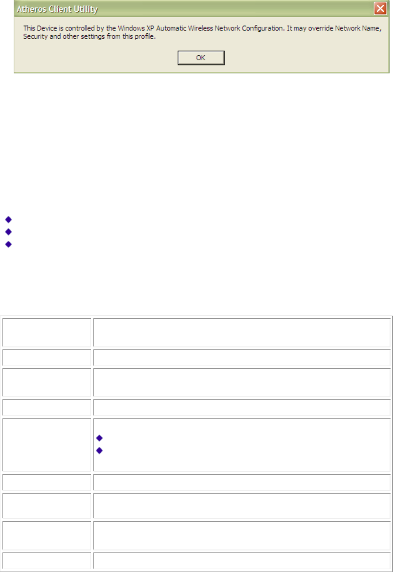
When Zero Configuration is in use, a pop-up message is displayed on the ACU when
you attempt to create or edit a configuration profile from the Profile Management tab of
the ACU.
To turn Zero Configuration off on Windows XP, take the following steps:
1. In Windows XP, open the Wireless Network Configuration Properties dialog box.
2. Clear the check box “Use Windows to configure my wireless network settings” to set
Zero Configuration. When this check box is cleared, all profile settings are controlled
by the configuration profile, which is set up from the ACU Profile Management tab.
Check the Status Information or Diagnostics
The client utility includes a number of tools to display current diagnostics and status
information.
Check current status
Check driver information
Check receive and transmit diagnostics
Current Status
The Current Status tab contains general information about the program and its
operations. The Current Status tab does not require any configuration. The following
table describes the items found on the Current Status screen.
Profile Name
The name of the current selected configuration profile. Set up the
configuration name on the General tab.
Link Status
Shows whether the station is associated to the wireless network.
Wireless Mode
Displays the wireless mode. Configure the wireless mode on the
Advanced tab.
IP Address
Displays the computer's IP address.
Network Type
The type of network the station is connected to. Options include:
Infrastructure (access point)
Ad Hoc
Confi
g
ure the network t
y
pe on the Advanced tab.
Current Channel
Shows the currentl
y
connected channel.
Server Based
Authentication
Shows whether server based authentication is used.
Data Encryption
Displays the encryption type the driver is using. Configure the
encryption type on the Security tab.
Signal Strength
Shows the strength of the signal.
Click the Advanced button to see the advanced status diagnostics.

Adapter Information Button
The Adapter Information button contains general information about the network
interface card (the wireless network adapter) and the network driver interface
specification (NDIS) driver. Access the adapter information from the Diagnostics tab.
Card Name Name of the wireless network adapter.
MAC Address MAC address of the wireless network adapter.
Driver Driver name and path of the wireless network adapter driver.
Driver Version Version of the wireless network adapter driver.
Driver Date Creation date of the wireless network adapter driver.
Client Name Name of the client computer.
Diagnostics Tab
The ACU Diagnostics tab provides allows retrieval of receive and transmit statistics. The
Diagnostics tab does not require any configuration. It lists these receive and transmit
diagnostics for frames received by or transmitted by the wireless network adapter:
Multicast packets transmitted and received
Broadcast packets transmitted and received
Unicast packets transmitted and received
Total bytes transmitted and received
The Adapter Information button has general information about the wireless network
adapter and NDIS driver. The Advanced Statistics button to shows statistics for
diagnostics for frames received by or transmitted to the wireless network adapter:

Transmitted Frames
Frames transmitted
OK
Frames retried
Frames dropped
No ACK frames
ACK frames
RTS frames
Clear-to-send (CTS)
frames
No CTS frames
Retried RTS frames
Retried data frames
Received Frames
Frames received OK
Beacons
Frames with errors
CRC errors
Encryption errors
Duplicate frames
AP mismatches
Data rate mismatches
Authentication time-out
Authentication rejects: the number of AP authentication
failures received by the wireless network adapter
Association time-out
Association rejects: the number of AP authentication rejects
received by the wireless network adapter
Standard MIC OK
Standard MIC errors
CKIP MIC OK
CKIP MIC errors
Scan Available Networks
Click the Scan button on the Profile Management tab to scan for available infrastructure
and ad hoc networks. On this list, click Refresh to refresh the list at any time.
Connecting to a different network
Highlight a network name and click the Activate button to connect an available
network. If no configuration profile exists for that network, the Profile Management
window opens to the General tab. Fill in the profile name and click OK to create the
configuration profile for that network.
Infrastructure
(AP) Network
Connected
Infrastructure
(AP) Network
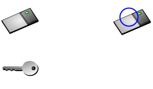
Ad Hoc
Network
Connected Ad
Hoc Network
Encryption
Active

Display Settings
To change the display settings, choose Options > Display Settings from the menu. The
display settings dialog box contains tools to set the:
Si
g
nal Stren
g
th Displa
y
Units Sets the units used when displaying signal
strength: percentage (%) or dBm.
Refresh Interval Use the up/down arrows to set the display refresh
interval in seconds.
Data Display Sets the display to cumulative or relative:
Relative displays the change in statistical data
since the last update.
Cumulative displays statistical data collected
since openin
g
the profile.
ACU Tools
Use the Action menu to access the Client Utility tools:
Enable/Disable Radio Enable or disable the RF Signal on all station
reference designs.
Enable/Disable Tra
y
Icon Enable or disable the tray icon.
Troubleshooting Run the optional Troubleshooting Utility.
Manual LEAP Login Log in to LEAP manually, if LEAP is set to
manually prompt for user name and password on
each login.
Reauthenticate Reauthenticate to a LEAP-configured access
point.
Exit Exit the Client Utility application.

Tray Icon
The tray icon appears at the bottom of the screen, and shows the signal strength using
colors and the received signal strength indication (RSSI).
Hold the mouse cursor over the tray icon to display the current configuration profile
name and association, as well as transmit and receive speed and the wireless adapter
name and IP address. Right-click on the tray icon to:
Help Open the online help.
Open Client Utility Launch the
Client Utility (ACU).
Use the ACU to configure
a profile or view status and statistics information.
Troubleshooting Run the Troubleshooting Utility.
Preferences Set the ACU startup and menu options. Check to start the
program automatically when Windows starts, and check
menu items that should appear on the popup menu.
Enable/Disable Radio Enable or disable the RF signal.
Manual LEAP Login Log in to LEAP
manually, if LEAP is set to manually prompt
for user name and password on each login.
Reauthenticate Reauthenticate to the access point.
Select Profile Click a configuration profile name to switch to. If no
configuration profile exists for a connection, add a profile.
Show Connection
Status This window displays connection information:
Active Profile Displays the active configuration profile name.
Auto Profile
Selection Shows whether auto profile selection is enabled.
Connection
Status Displays whether the adapter is connected to a
wireless network.
Link Quality Lists the quality of the link connection.
SSID Displays the SSID of the associated network.
Access Point
Name Shows the name of the AP the wireless adapter is
connected to.
Access Point
IP Address Shows the IP address of the access point the
wireless adapter is connected to.
Link Speed Lists the speed of the link connection.
Adapter IP
Address Displays the IP address of the wireless adapter.
Exit Exit the Client Utility application.
The colors are defined as follows:
Color Quality RSSI*
Green Excellent 20 dB +
Green Good
10-20 dB +
Yellow Poor
5-10 dB
Red Poor < 5 dB
Gray No Connection No Connection
*Received signal strength indication RSSI. Displayed in dB or percentage. Enable or
disable the tray icon in the Action menu.
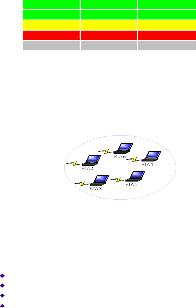
Ad Hoc Mode
In ad hoc mode, a wireless network adapter works within an independent basic service
set (IBSS), as illustrated here. All stations communicate directly with other stations
without using an access point (AP).
To connect to an ad hoc network, configure the profile for ad hoc mode. Ad Hoc
operation may be limited by Hardware to meet regulatory requirements.
Ad Hoc Mode Profile Configuration
To configure a profile in ad hoc mode, change the Network Type in the Profile
Management's Advanced tab. For ad hoc mode, modify the settings:
Network Name (on General Tab)
Transmit Power Level
802.11b Preamble (if using 802.11b)
Wireless Mode When Starting an Ad Hoc Network
Make sure to also edit the General and Security tabs.
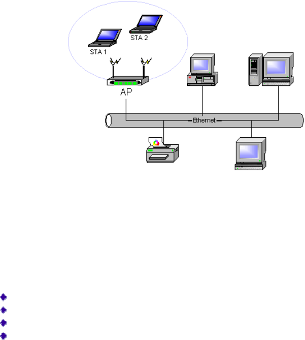
Infrastructure (Access Point) Mode
In infrastructure (access point (AP)) mode, the wireless network adapter participates in a
basic service set (BSS) as a station, and communicates with the other stations through an
AP, as illustrated here.
To connect to an access point network, configure the profile for access point mode.
Infrastructure (Access Point) Mode Profile Configuration
To configure a profile in infrastructure (access point) mode, change the Network Type in
the Advanced tab. For access point mode, modify the settings:
Power Save Mode
802.11b Preamble (if using 802.11b)
Wireless Mode
802.11 Authentication Mode
Make sure to also edit the General and Security tabs.
Uninstall an Old Driver
Uninstall an old driver before upgrading to a new NDIS driver release.
To remove the newly installed driver from the system if the system does not have
previously installed versions of the NDIS driver, proceed to Step 4.
1. To remove the NDIS driver from the OS, go to Device Manager, right-click AR500x
Wireless Network Adapter, and choose Uninstall.
2. Click OK to uninstall the device.
3. When the device is uninstalled from Device Manager, search for and delete the
driver files that reside in the system.
a. Go to the Start menu and choose Search > For Files or Folders.
b. Enter oem*.inf in the Search for files or folders named: field, and enter in
the Containing text: field.
c. Click Search Now. A few files matching these criteria are possible, if previous
drivers have not been removed properly.
d. Choose the files that have been found and delete them from the system.
4. To complete the uninstallation, remove the file ar5211.sys from the folder
\WINNT\system32\drivers.
Additional Security Features
These security features prevent attacks on a wireless network's WEP keys. The wireless
adapter automatically supports each of these features, but these features must be enabled
on the access point.
Message Integrity Check (MIC)
MIC prevents bit-flip attacks on encrypted packets. In a bit-flip attack, someone
intercepts an encrypted message retransmits it after some alterations. Thus the receiver
accepts the message as legitimate. The MIC adds some bytes to each packet to protect it
against tampering.
Temporal Key Integrity Protocol (TKIP)
This feature prevents attacks on WEP in which someone catches encrypted packets and
uses their initialization vector (IV) to decipher the WEP key. TKIP removes the
predictability to protect both unicast and broadcast WEP keys.
Broadcast Key Rotation
EAP authentication provides dynamic unicast WEP keys for wireless adapters, but uses
static broadcast keys. In broadcast WEP key rotation, the access point supplies a
dynamic broadcast WEP key and changes it at intervals.

Advanced Status Information
Click the Advanced button on the Current Status tab of the Client Utility to see
advanced information about the program and its operations. The Current Status tab does
not require any configuration. The following table describes the items found on the
Advanced Status screen.
Network Name (SSID)
Displays the wireless network name.
Configure the network name on the General tab.
Server Based
Authentication
Shows whether server based authentication is used.
Data Encryption
Displays the encryption type the driver is using. Configure the
encryption type on the Security tab.
Authentication Type
Displays the authentication mode.
Configure the authentication mode on the General tab.
Messa
g
e Inte
g
rit
y
Check
Shows whether MIC is enabled. MIC prevents bit-flip attacks on
encrypted packets.
Associated AP Name
Displays the name of the access point the wireless adapter is
associated to.
Associated AP IP
Address
Shows the IP address of the access point the wireless adapter is
associated to.
Associated AP MAC
Address
Displays the MAC address of the access point the wireless
adapter is associated to.
Power Save Mode
Shows the power save mode. Power management is disabled in
ad hoc mode.
Configure the power save mode on the Advanced tab.
Current Power Level
Displays the transmit power level rate in mW.
Current Signal Strength
Shows the current signal strength in dBm.
Current Noise Level
Displays the current noise level in dBm.
Up Time
Shows how long the client adapter has been receiving power (in
hours:minutes:seconds). If the adapter runs for more than 24
hours, the display shows in days:hours:minutes:seconds.
802.11b Preamble
Displays the 802.11b preamble format.
Configure the preamble format on the Advanced tab.
Current Receive Rate
Shows the current receive rate in Mbps.
Current Transmit Rate
Displays the current transmit rate in Mbps.
Channel
Shows the currently connected channel.
Frequency
Displays frequency the station is using.
Channel Set
Shows the current channel set.
Federal Communication Commission Interference Statement
This device complies with Part 15 of the FCC Rules. Operation is subject to the following
two conditions: (1) This device may not cause harmful interference, and (2) this device
must accept any interference received, including interference that may cause undesired
operation.
This equipment has been tested and found to comply with the limits for a Class B digital
device, pursuant to Part 15 of the FCC Rules. These limits are designed to provide
reasonable protection against harmful interference in a residential installation. This
equipment generates, uses and can radiate radio frequency energy and, if not installed
and used in accordance with the instructions, may cause harmful interference to radio
communications. However, there is no guarantee that interference will not occur in a
particular installation. If this equipment does cause harmful interference to radio or
television reception, which can be determined by turning the equipment off and on, the
user is encouraged to try to correct the interference by one of the following measures:
- Reorient or relocate the receiving antenna.
- Increase the separation between the equipment and receiver.
- Connect the equipment into an outlet on a circuit different from that
to which the receiver is connected.
- Consult the dealer or an experienced radio/TV technician for help.
FCC Caution: Any changes or modifications not expressly approved by the party
responsible for compliance could void the user's authority to operate this equipment.
This transmitter must not be co-located or operating in conjunction with any other
antenna or transmitter.
Operations in the 5.15-5.25GHz band are restricted to indoor usage only.

Radiation Exposure Statement:
This equipment complies with FCC radiation exposure limits set forth for an
uncontrolled environment. This equipment should be installed and operated with
minimum distance 20cm between the radiator & your body.
This device is intended only for OEM integrators under the following conditions:
1) The antenna must be installed such that 20 cm is maintained between the antenna
and users, and
2) The transmitter module may not be co-located with any other transmitter or antenna.
As long as 2 conditions above are met, further transmitter test will not be required.
However, the OEM integrator is still responsible for testing their end-product for any
additional compliance requirements required with this module installed
IMPORTANT NOTE: In the event that these conditions can not be met (for example
certain laptop configurations or co-location with another transmitter), then the FCC
authorization is no longer considered valid and the FCC ID can not be used on the final
product. In these circumstances, the OEM integrator will be responsible for re-evaluating
the end product (including the transmitter) and obtaining a separate FCC authorization.
End Product Labeling
This transmitter module is authorized only for use in device where the antenna may be
installed such that 20 cm may be maintained between the antenna and users. The final
end product must be labeled in a visible area with the following: “Contains FCC ID:
N6C-SXSP242”. The grantee's FCC ID can be used only when all FCC compliance
requirements are met.
Manual Information To the End User
The OEM integrator has to be aware not to provide information to the end user
regarding how to install or remove this RF module in the user’s manual of the end
product which integrates this module.
The end user manual shall include all required regulatory information/warning as show
in this manual.
Industry Canada statement:
This device complies with ISED’s licence-exempt RSSs. Operation is subject to the following two
conditions: (1) This device may not cause harmful interference, and (2) this device must accept
any interference received, including interference that may cause undesired operation.
Le présent appareil est conforme aux CNR d’ ISED applicables aux appareils radio exempts de
licence. L’exploitation est autorisée aux deux conditions suivantes : (1) le dispositif ne doit pas
produire de brouillage préjudiciable, et (2) ce dispositif doit accepter tout brouillage reçu, y
compris un brouillage susceptible de provoquer un fonctionnement indésirable.
Caution :
(i) the device for operation in the band 5150-5250 MHz is only for indoor use to reduce the
potential for harmful interference to co-channel mobile satellite systems;
(ii) the maximum antenna gain permitted for devices in the bands 5250-5350 MHz and 5470-5725
MHz shall be such that the equipment still complies with the e.i.r.p. limit;
(iii) the maximum antenna gain permitted for devices in the band 5725-5850 MHz shall be such
that the equipment still complies with the e.i.r.p. limits specified for point-to-point and
non-point-to-point operation as appropriate; and
(iv) the worst-case tilt angle(s) necessary to remain compliant with the e.i.r.p. elevation mask
requirement set forth in Section 6.2.2(3) shall be clearly indicated.
(v) Users should also be advised that high-power radars are allocated as primary users (i.e.
priority users) of the bands 5250-5350 MHz and 5650-5850 MHz and that these radars could
cause interference and/or damage to LE-LAN devices.
Avertissement:
Le guide d’utilisation des dispositifs pour réseaux locaux doit inclure des instructions précises
sur les restrictions susmentionnées, notamment :
(i) les dispositifs fonctionnant dans la bande 5150-5250 MHz sont réservés uniquement pour une
utilisation à l’intérieur afin de réduire les risques de brouillage préjudiciable aux systèmes de
satellites mobiles utilisant les mêmes canaux;
(ii) le gain maximal d'antenne permis pour les dispositifs utilisant les bandes de 5250 à 5
350 MHz et de 5470 à 5725 MHz doit être conforme à la limite de la p.i.r.e;
(iii) le gain maximal d'antenne permis (pour les dispositifs utilisant la bande de 5 725 à 5
850 MHz) doit être conforme à la limite de la p.i.r.e. spécifiée pour l'exploitation point à
point et l’exploitation non point à point, selon le cas;

(iv) les pires angles d’inclinaison nécessaires pour rester conforme à l’exigence de la p.i.r.e.
applicable au masque d’élévation, et énoncée à la section 6.2.2 3), doivent être clairement
indiqués.
(v) De plus, les utilisateurs devraient aussi être avisés que les utilisateurs de radars de haute
puissance sont désignés utilisateurs principaux (c.-à-d., qu’ils ont la priorité) pour les bandes
5250-5350 MHz et 5650-5850 MHz et que ces radars pourraient causer du brouillage et/ou des
dommages aux dispositifs LAN-EL.
Radiation Exposure Statement:
The product comply with the Canada portable RF exposure limit set forth for an uncontrolled
environment and are safe for intended operation as described in this manual. The further RF
exposure reduction can be achieved if the product can be kept as far as possible from the user
body or set the device to lower output power if such function is available.
Déclaration d'exposition aux radiations:
Le produit est conforme aux limites d'exposition pour les appareils portables RF pour les Etats-
Unis et le Canada établies pour un environnement non contrôlé.
Le produit est sûr pour un fonctionnement tel que décrit dans ce manuel. La réduction aux
expositions RF peut être augmentée si l'appareil peut être conservé aussi loin que possible du
corps de l'utilisateur ou que le dispositif est réglé sur la puissance de sortie la plus faible si une
telle fonction est disponible.
DETACHABLE ANTENNA USAGE
This radio transmitter (IC: 4908A-SXSP242 / Model: SX-SP242) has been approved by Industry
Canada to operate with the antenna type listed below with maximum permissible gain indicated.
Antenna types not included in this list, having a gain greater than the maximum gain indicated
for that type, are strictly prohibited for use with this device.
Le présent émetteur radio (IC: 4908A-SXSP242 / Model: SX-SP242) a été approuvé par Industrie
Canada pour fonctionner avec les types d'antenne énumérés ci-dessous et ayant un gain
admissible maximal. Les types d'antenne non inclus dans cette liste, et dont le gain est supérieur
au gain maximal indiqué, sont strictement interdits pour l'exploitation de l'émetteur.
Transmitter
Circuit Brand Model Ant.
Type
2.4GHz
Gain with
cable loss
(dBi)
5GHz Gain
with cable loss
(dBi)
2.4GHz
Cable
Loss (dBi)
5G Cable
Loss(dBi) Connector
Type
Cable
Length
(mm)
Chain
(0)+(1) WNC 81-EBJ15.005 PIFA 3.62
Band 1&2:
3.08
1.15
Band 1&2:
1.70
IPEX 300
Band 3: 4.76 Band 3: 1.74
Band 4: 4.76 Band 4: 1.79

Transmitter
Circuit Brand Model Antenna
Type
2.4G gain
with cable
loss (dBi)
5G gain
with cable
loss (dBi)
2.4G
cable
loss
(dBi)
5G
cable
loss
(dBi)
Connector
Type Cable
Length
Chain(0) QCA SX-SP242-Ant PCB 1.72 1.91
NA NA
NA
NA