Silex Technology TROY500 Wireless Serial Server User Manual
Silex Technology, Inc. Wireless Serial Server Users Manual
Users Manual

Serial Server
Ethernet and Wireless Serial Servers
Installation and User’s Guide
Part Number 40179-120
Revision X5
Product Photo

Notice
TROY GROUP, INC. SPECIFICALLY DISCLAIMS THE IMPLIED WARRANTIES OF MERCHANTABILITY AND
FITNESS OF THIS PRODUCT FOR A PARTICULAR PURPOSE. TROY shall not be liable for any errors contained in this
manual or for any damages resulting from loss of use, data, profits, or any incidental or consequential damages arising from the
use of TROY products or services. The information contained in this documentation is subject to change without notice.
Trademarks
HP, HP/UX, LaserJet, DesignJet, DeskJet, PaintJet, JetDirect, and JetAdmin are trademarks of Hewlett-Packard Company. DEC,
DECserver, VMS, LAT, and ULTRIX are trademarks of Digital Equipment Corporation. UNIX is a trademark of UNIX Systems
Laboratories. Ethernet is a trademark of Xerox Corporation. PostScript is a trademark of Adobe Systems Incorporated.
NetWare is a trademark of Novell, Inc. Apple, Macintosh, LaserWriter, and AppleTalk are trademarks of Apple Computer, Inc.
IBM, LAN Server, and AIX are trademarks of International Business Machines Corporation. LAN Manager, Windows, and MS-
DOS are trademarks of Microsoft Corporation. VINES is a trademark of Banyan Systems Inc. PrintKit is a trademark of
Northlake Software. QADD is a trademark of Network Compatibility Group. LAN Attached and UNIX Printing for VINES is a
trademark of Incognito Software Inc. ExtendView, Xadmin 32, and WebXAdmin are trademarks of TROY Group, Inc. TROY
is a registered trademark of TROY Group, Inc.
Information and descriptions contained herein are the property of TROY Group, Inc. Such information and descriptions may not
be copied, disseminated, or distributed without the express written consent of TROY Group, Inc. This publication is subject to
change without notice.
TROY Group, Inc.
2331 S. Pullman Street
Santa Ana, CA 92705
TEL: (949) 250-3280
FAX: (949) 250-8972
http://www.troygroup.com
sales@troygroup.com
© Copyright 2004 TROY Group, Inc.
Printed in the United States of America
July 1, 2004

Serial Server User’s Guide
Document #40179-120 Rev. X5 i
TABLE OF CONTENTS
Section 1 – Product Overview
Introduction............................................................................................................................ 1-1
Package Contents................................................................................................................... 1-1
About this User’s Guide.........................................................................................................1-1
Windows System Requirements ............................................................................................ 1-2
Wireless Serial Server Requirements..................................................................................... 1-2
Component Descriptions........................................................................................................ 1-3
LED Indicators................................................................................................................ 1-4
Pushbutton Functions...................................................................................................... 1-4
Factory Default Settings ........................................................................................................1-5
Configuration Notes........................................................................................................ 1-5
Section 2 – Hardware Installation
Install the TROY Serial Server (for wired and wireless models) .......................................... 2-1
Section 3 – Configuration and Management
Configuration Options ...........................................................................................................3-1
ExtendView Utility......................................................................................................... 3-1
Installing the ExtendView Utility (Windows Operating Systems).......................................... 3-1
Web Browser Interface ................................................................................................... 3-1
HP Web JetAdmin Utility............................................................................................... 3-1
Command Console..........................................................................................................3-2
Configuring the Serial Server via an Ethernet Connection.................................................... 3-2
Configuring the Serial Server via a Serial Connection.......................................................... 3-4
First-Time Configuration of the Wireless Serial Server Uisng 802.11b................................ 3-5
Verifying the Serial Server’s Connection to a Serial Device................................................. 3-6
Changing the Serial Settings.................................................................................................. 3-7
Changing the Baud Rate ................................................................................................. 3-7
Changing the Serial Port Protocol................................................................................... 3-7
Using the Modbus Protocol ................................................................................................... 3-8
Serial Transmission Modes............................................................................................. 3-8
Typical Modbus Applications......................................................................................... 3-8
Changing the Modbus Settings....................................................................................... 3-8
Section 4 - Troubleshooting
Introduction............................................................................................................................ 4-1
Troubleshooting Installation Problems.................................................................................. 4-1
Troubleshooting Network Configuration Problems............................................................... 4-1
Troubleshooting Windows Problems..................................................................................... 4-2
Troubleshooting Wireless Configuration Problems............................................................... 4-2
Section 5 – Where to Get Help
Obtaining Technical Assistance............................................................................................. 5-1
Worldwide Web Support ................................................................................................ 5-1
Technical Support........................................................................................................... 5-1
Returning Products ................................................................................................................ 5-2
Contacts ................................................................................................................................. 5-2
Technical Support........................................................................................................... 5-2

Serial Server User’s Guide
Document #40179-120 Rev. X5 ii
Appendix A – Safety and Regulatory Notices
Information for United States Users ..................................................................................... A-1
Declaration of Conformity (FCC)......................................................................................... A-2
Information for Canadian Users (IC notice) ......................................................................... A-2
Information for European Users ........................................................................................... A-3
Declaration of Conformity (CE)........................................................................................... A-3
Appendix B – Product Specifications
Appendix C – Serial Port Pinouts
Serial Port Pinouts .................................................................................................................C-1
TCP Port Connections............................................................................................................C-1
Appendix D – Alternate Power Source Configuration
RS-232 Port........................................................................................................................... D-1
RS-422 / 485 Full Duplex Port ............................................................................................. D-1
RS-485 Half-Duplex Port ..................................................................................................... D-2
Appendix E – Loading New Firmware
Serial Server User’s Guide
Document #40179-120 Rev. X5 1-1
Section 1: Product Overview
Introduction
The TROY Serial Server is a high-performance, standalone
device designed to connect a wide range of serial devices (i.e.,
security devices, telecommunications equipment, modems,
data display devices, industrial instrumentation, etc.) to an
Ethernet network. The TROY Serial Server supports RS232,
RS422, or RS485 serial interfaces at a variety of baud rates
(data transmission speeds), automatically senses both
100baseTX Fast Ethernet and 10baseT Ethernet network
connections, and the wireless version allows connections to
802.11b wireless networks as well. The TROY Serial Server
also supports the ModBus protocol (a popular industrial device
communications protocol), which is used to communicate with
many types of industrial devices (e.g., instruments, meters,
controllers, switches, etc.) over a serial-to-Ethernet connection.
The installation can be performed by the least-experienced users, while providing networking
professionals with advanced features for configuration. TROY is confident that you will enjoy the many
features of the Serial Server. For more information on this product or for downloading firmware upgrades,
visit the TROY web site at http://www.troygroup.com/.
Package Contents
TROY Serial Server
Power supply adapter
TROY Serial Server Installation CD
Hardware Installation Guide
About This User’s Guide
This User’s Guide contains information on system requirements, basic troubleshooting, and instructions
on the following:
Installing the Serial Server hardware
Configuring the Serial Server for use with a serial device
Configuring the Serial Server for use on your network
Configuring the Serial Server using the TROY ExtendView Utility
IMPORTANT
"Use Adobe Acrobat Reader 5.0 or higher to view or print the PDF files contained on the CD.
"Print out, fill in, and mail back the warranty registration card provided on the TROY Serial Server
Installation CD, or register online at http://www.troygroup.com.
Product Photo
NOTE: The TROY Serial Server can be used with a variety of network operating systems and protocols. Refer to
Section 3: Management Methods for detailed information.

Serial Server User’s Guide
Document #40179-120 Rev. X5 1-2
Windows™ System Requirements
To configure the settings of the TROY Serial Server (wired and wireless versions) using the provided
ExtendView Utility in Windows, your Windows-based system should include the following components:
A PC with a 133 MHz or higher processor
Microsoft Windows 98SE, ME, 2000, XP, or 2003 server operating system
At least 64 MB of RAM (memory)
At least 10 MB of free hard disk space (to install the software)
A CD-ROM drive (to load the software)
An Internet connection through a cable or DSL modem, or an external dial-up or ISDN modem
(for online product registration)
Wireless Serial Server Requirements (for wireless models only)
To use the wireless TROY Serial Server, you need an 802.11b wireless network consisting of either of the
following:
An 802.11b wireless-enabled PC connected directly to the serial server (Ad-Hoc or Peer-to-Peer
Mode).
An 802.11b wireless access point that allows wireless and wired Ethernet-enabled computers to
connect to the serial sever.
To configure the wireless TROY Serial Server, you will need the following information from your wireless
network administrator:
Wireless Mode used (Infrastructure or Ad-Hoc)
The SSID (service set identifier) for your wireless network.
The Radio Frequency Channel of the wireless network.
If you are using TCP/IP (recommended for Windows Networks) and are not connected to a DHCP
server (for obtaining an IP Address automatically), you will need a unique IP Address for the
wireless Serial Server (for example: 192.168.1.14). If the Serial Server is not on the same IP
subnet as the computers you are printing from, you will also need a subnet mask and a router
(default gateway) address.
Wireless Security Settings (WEP keys, 802.1x settings, etc.)
NOTE: If you require assistance for installing or configuring your serial server, ask your system administrator for
assistance, or contact TROY Technical Support at (800) 332-6427, between 8 AM and 8 PM, Monday through Friday,
Eastern Standard Time. Customers located outside the United States, call (304) 232-0899. European customers,
please call +49 (0) 7032-9454-21.

Serial Server User’s Guide
Document #40179-120 Rev. X5 1-3
Component Descriptions
The Serial Server includes the following components as described below:
Power connector – The power supply cable plugs into this connector.
Test button – Pressing this button for less than five seconds will print a test page (if the device is
connected to a serial printer). Pressing and holding this button for more than five seconds will
reset the serial server to factory default settings.
LED status indicators – used to indicate the operational states of the Serial Server. Refer to the
next page for detailed LED status light descriptions.
Ethernet port – This port (8-pin RJ45 jack) is used for connecting the Serial Server to an
Ethernet card, hub, router, or other wired access point for network access.
Serial port – This port (PC-compatible 9-pin male DB-9 connector) can be configured to connect
the Serial Server to a serial device that uses the RS232, RS422, or RS485 serial interface.
Photo of device
Photo of device
Serial Server User’s Guide
Document #40179-120 Rev. X5 1-4
LED Indicators
The TROY Serial Server provides three multifunction LED (Light Emitting Diode) indicators (yellow, green,
and orange) for easy monitoring. The following table defines the function of each LED.
FUNCTION STATE STATUS
ON The device is receiving power
OFF The device is not receiving power
POWER
(ORANGE)
Blinking The device’s power supply is malfunctioning
Yellow OFF
Green OFF No network activity
Yellow ON
Green OFF 10baseT network active
Yellow Blinking
Green OFF 10baseT network data received
Yellow OFF
Green ON 100baseTX network active
Yellow OFF
Green Blinking 100baseTX network data received
Yellow ON
Green ON Wireless network active (wireless models only)
NETWORK
STATUS
(YELLOW /
GREEN)
Yellow Blinking
Green Blinking Wireless network data received (wireless models only)
Pushbutton Functions
Action Result
Depress for less than 5 seconds Generates configuration data that can be viewed using a
terminal emulator (e.g., Windows Hyper Terminal) or
other serial device that can display ASCII characters, or it
will initiate a test page if the serial server is connected to
a serial printer.
Depress for more than 5 seconds Resets the serial server’s configuration to factory defaults
(cold reset). The unit will automatically re-initialize after
updating the configuration memory.
Depress for 3 seconds during power up Places the device into console configuration mode, which
can be used to configure the device via the Serial
Server’s serial port.

Serial Server User’s Guide
Document #40179-120 Rev. X5 1-5
Factory Default Settings
The TROY Serial Server is shipped with a default configuration that will work with the most common
serial-to-Ethernet and wireless connections. The default settings can be changed to suit specific
installation requirements via the ExtendView Utility, the embedded Web server, or via a Telnet connection
to the serial server’s internal console. The factory default settings can be easily restored at any time by
performing a cold reset (press and hold the pushbutton on the device for more than five seconds).
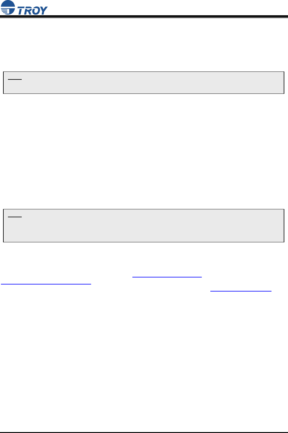
Port Parameters and Modbus Settings
Parameter Description Settings
CHARACTER bits per character 7, 8 (default)
FLOW flow control NO (default), XO, CT
PARITY parity NONE (default), EVEN, ODD, MARK, or SPACE
SPEED baud rate (bits per second) 300, 600, 1200, 2400, 3600, 4800, 7200, 9600
(default), 14400, 19200, 38400, 57600, 76800,
115200 (console port default), 230400, 460800
STOP stop bits per character 1 (default), 2
MODE line mode (serial port protocol) 232 (default), 422, 485, 485HD, Disabled
ECABLE E-Cable mode (for TCP connections) Enable, Disable (default)
ECADDR E-Cable destination IP address (set by user)
ECONN E-Cable connection attempt time 20 seconds
ECPORT E-Cable destination IP port number 9100 (default), or set by user
MULTI multidrop protocol Host (default), Modbus
MBTYPE Modbus attached device type RTU slave (default)2, ASCII slave
MBINIT Modbus initialization delay interval 100 – 3276 ms (default = 100 ms)
MBAUTOID Modbus auto slave ID Enable (default)1, Disable
MBCHARTMO Modbus character timeout interval 10 – 3000 ms (default = 100 ms)
MBMSGTMO Modbus message timeout interval 10 – 3000 ms (default = 1000 ms)
(N/A) Modbus/TCP Exception handling Enable, Disable (default)
Configuration Notes
1. The Modbus/TCP protocol contains a “Unit ID” field to identify multiple Modbus slave devices that are accessible at a single IP address.
When the Modbus/TCP command contains a Unit ID, the Modbus Gateway can pass the Unit ID to Modbus serial devices, which allows
multiple serial devices to be linked with a Modbus Gateway. When Auto Slave ID is enabled, a unit ID will be assigned automatically. If
the Auto Slave ID is disabled, a unit ID (any number between 1 and 247) must be manually assigned in the Slave ID field.
2. When the Modbus serial protocol is set to Modbus/RTU, the Serial Server is ready to receive connection requests from Modbus/TCP
master devices. Each message packet is determined by a character timeout. An incorrect character timeout may cause a CRC (Cyclic
Redundancy Check) checksum error. Modbus ASCII slave mode functions the same as Modbus/RTU slave mode, except that the data
format is Modbus/ASCII.
3. The Modbus/TCP Exception is in effect when the Modbus Gateway connects a Modbus/TCP Master with Modbus serial slave devices.
When the Modbus Gateway cannot get a response from Modbus serial devices, the Modbus serial protocol will not respond to the master
device. However, the TCP protocol has a longer waiting time, which could cause a network traffic problem for Modbus/TCP. For this
reason, the Modbus Gateway can automatically send a Modbus exception code 16 to the Modbus/TCP master device when there is not
response from the Modbus serial slave devices, thereby making overall network communication much more efficient.

Serial Server User’s Guide
Document #40179-120 Rev. X5 2-1
Section 2: Hardware Installation
Install the TROY Serial Server (for wired and wireless models)
Follow the steps below to install the TROY Serial Sever. In most cases, the Serial Server’s factory default
settings should be sufficient for most serial connections; however, some of the configuration settings may
have to be changed for your particular installation. The TROY Serial Server can be wall mounted, set on
the desktop, or mounted using the optional DIN rail kit (available from TROY).
1. Before attempting to install the TROY Serial Server, make sure you have installed and set up your
serial device as described in the documentation that came with the device.
2. Write down the 12-digit MAC (Media Access Code) address printed on the label located on the
bottom of the Serial Server (for example: 004017023F96). You may need this number in order to
configure the Serial Server.
3. Connect the Serial Server to your serial device using a standard PC-compatible 9-pin (DB-9) serial
cable for RS-232 type devices (refer to Appendix A for pinout descriptions). A custom cable may be
required for RS-422 and RS-485-type serial devices. For RS-422/RS-485-type devices, a 120-ohm
terminating resistor may be required at the receiving end of a differential pair if the device is at the
end of the cable (refer to Appendix C for detailed information).
4. Plug the Serial Server power supply adapter into a suitable AC receptacle, and then plug the power
supply cable into the Serial Server. The Serial Server will run through a sequence of power-up
diagnostics for a few seconds.
If the Serial Server is operating properly, the LEDs will blink momentarily and then go out, the
yellow and green LEDs will illuminate if the wireless network is active, and the orange LED
will illuminate, indicating the device is receiving power (refer to page 1-4 for detailed LED
status descriptions).
The unit powers up in the Normal mode, which provides for connection from the network to
device(s) connected to the serial port of the Serial Server.
If the orange LED blinks continuously in a regular pattern, a problem exists. If this is the
case, try powering the unit OFF and then ON again. If the problem persists, refer to the
Troubleshooting section in this User’s Guide.
5. Connect the Serial Server to your network through a switch or hub using a category 5 (CAT5)
Ethernet cable. The Serial Server’s IP address must be configured before a network connection is
available. If your network offers DHCP (Dynamic Host Configuration Protocol), the Serial Server will
automatically search for a DCHP server upon power up and obtain an IP address. If your network
does not offer DHCP, a static (fixed) IP address must be assigned (see your system administrator for
assistance). In most cases, a fixed IP address is preferred because a DHCP server may not always
assign the same IP address to the Serial Server when the Serial Server is powered ON.
The Serial Server also supports the following protocols. See your system administrator for help.
arp
rarp
BootP
NOTE: The IP address must be within a valid range, unique to your network, and in the same subnet as your PC
(refer to page A-1 for a list of TCP port connections).
NOTE: For wireless Serial Servers, if a wired connection is established to the unit, the wireless link will be disabled.

Serial Server User’s Guide
Document #40179-120 Rev. X5 3-1
Section 3: Configuration and Management
Configuration Options
After the hardware installation has been successfully completed, the Serial Server can be configured and
managed via an Ethernet and/or wireless connection using the TROY ExtendView Utility (recommended),
the embedded web (HTTP) server pages, or the Serial Server’s internal configuration console, which can
be accessed via a Telnet connection or directly through the Serial Server’s serial port. Additional options
for configuration and management of the Serial Server are available as third-party utilities that can be
downloaded from their respective web sites as noted below. If you are using a wireless Serial Server,
you can still configure it via an Ethernet connection or optionally configure it via a wireless connection as
described on Page 3-5.
ExtendView Utility
a Windows TCP/IP utility used for configuring the Serial Server’s port, network, and wireless
settings.
uses a 32-bit graphical user interface.
works with Windows PCs running the TCP/IP protocol.
included on the TROY serial server installation CD.
can be downloaded from the TROY web sites:
USA: http://www.troygroup.com
Europe: http://www.troygroup.de
after installation, this utility can be run from the START menu.
INSTALLING THE EXTENDVIEW UTILITY (WINDOWS OPERATING SYSTEMS):
1. Ensure your PC is connected and has access to your network.
2. Connect an available Ethernet cable from your network hub to the Serial Server. Ensure the
Serial Server is powered ON.
3. Insert the CD supplied with your Serial Server into the CD-ROM drive of your computer. The CD
should automatically start and display a menu screen. Click on Install Software.
4. Select TCP/IP Management Utilities, and then click on Next.
5. Select ExtendView, and then click on Install. After the installation is complete, you can start the
ExtendView utility by clicking on Start, Programs, TROY GROUP, and then ExtendView.
Web Browser Interface
allows you to configure the print server with a standard web browser (e.g., Netscape Navigator or
Microsoft Internet Explorer).
no additional software is needed on the system.
can be used on any system that supports web browser capabilities.
type the IP address into your web browser address bar to connect.
the default password is ACCESS (not case sensitive).
HP Web JetAdmin Utility
a web browser-based utility (works with browsers like Internet Explorer or Netscape Navigator).
can be downloaded from the HP web site http://www.hp.com.

Serial Server User’s Guide
Document #40179-120 Rev. X5 3-2
Command Console
a command-line-oriented console.
contains some advanced features not available through ExtendView or the Web Browser
Interface.
the default password is ACCESS.
can be accessed via TELNET or via a direct connection to the Serial Server’s serial port.
type HELP for a list of console commands.
Configuring the Serial Server via an Ethernet Connection
For Microsoft Windows operating systems, the TROY ExtendView Utility is the recommended method of
configuring one or more Serial Servers on your network. Once the Serial Server obtains an IP address
(occurs automatically when the unit is powered ON and connected to a DHCP netowrk), the ExtendView
Utility’s auto-discovery feature will search for and locate all Serial Severs on the network and then display
the IP address for each discovered Serial Server.
USING THE EXTENDVIEW UTILITY TO CONFIGURE THE SERIAL SEVER (WINDOWS OPERATING SYSTEMS):
1. Start the ExtendView Utility by clicking on Start, Programs, TROY GROUP, and then ExtendView.
2. When the Welcome screen appears, click on Next, choose any name for your View Name, select
Automatically create a view with default settings (or configure the view to your preferences), and
then click on Finish.
3. Right-click on the Serial Server that you want to configure from the displayed list, and then left-click
on Configuration. The default Serial Server name is TWC_xxxxxx (where xxxxxx is the last six digits
of the MAC address from the label located on the back of the Serial Server).
4. If you are using TCP/IP (recommended for Windows) and you do not have a DHCP server (see note
below), you will need to manually assign a valid IP Address (if you are not sure what IP address is
valid, ask your network administrator), and then click on OK.
5. Configure the 802.11b wireless settings (for wireless models only). To operate on an 802.11b
network, the Serial Server configuration must be set to the same configuration as your wireless
network to allow the Serial Server to communicate over your wireless network. All nodes of a
wireless network need to have the same settings to allow communication between the devices.
wireless mode (ad-hoc or infrastructure)
SSID channel
data rate
wireless security settings (WEP keys, 802.1x settings, etc.)
NOTE: If you are using DHCP on your network, the Serial Server should have acquired valid IP settings at this point
and no further configuration is necessary. However, for most installations, a static IP address is preferred. If your
DHCP server does not allow the Serial Server to keep its assigned IP address permanently, then you must manually
assign an IP address. In this case, use a static IP address outside the range reserved for DHCP (see your DHCP
server documentation for details). To assign a static IP address, right-click on the Serial Server in the menu, and
then select Configuration. On the TCP/IP tab, under IP Address Resolution, select Set Permanent, and assign a valid
static IP address for
y
our network. Click on O
K
to save the new settin
g
s.
Serial Server User’s Guide
Document #40179-120 Rev. X5 3-3
USING THE WEB BROWSER INTERFACE TO CONFIGURE THE SERIAL SERVER (NON-WINDOWS SYSTEMS):
To configure the Serial Server using non-Windows operating systems (e.g., Unix systems), a standard
web browser (e.g., Internet Explorer or Netscape Navigator) can be used to access the Serial Server’s
embedded Web (HTTP) server pages, which contain the Serial Server’s configuration options. No
additional software is required.
1. Ensure your PC is connected and has access to your network.
2. Connect an available Ethernet cable from your network hub to the Serial Server. Ensure the Serial
Server is powered ON.
3. Connect the Serial Server to the desired serial device, and ensure that the device is powered on and
ready. If the Serial Server is connected to a serial device that cannot display or print ASCII
characters, then it is recommended that another serial device capable of displaying or printing ASCII
characters be temporarily connected to the Serial Server in order to view the IP address assigned by
the DHCP server to the Serial Server.
4. With the serial device and Serial Server switched on and ready, press the Test button on the Serial
Server to send the Serial Server’s configuration data to the connected serial device. The serial
device should display or print the current IP address assigned to the Serial Server by your network
DHCP service. If your network does not use DHCP, then the Serial Server will have the default IP
address of 192.0.0.192. In any case, your computer must use an IP address other than the one used
by the Serial Server in order to establish a connection between the two devices.
5. Configure the 802.11b wireless settings (wireless Serial Servers only). To operate on an 802.11b
network, you must set the Serial Server’s wireless mode (ad-hoc or infrastructure), SSID channel,
data rate, and security settings (WEP keys, 802.1x settings, etc.) to the same configuration as the
wireless network you want the Serial Server to communicate on. All nodes of a wireless network
need to have the same settings in order to communicate with each other.
6. From the host computer, open a standard web browser (e.g., Internet Explorer, Netscape Navigator),
enter the IP address of the Serial Server into the address bar of the web browser, and then press
Enter. The Web Browser Utility screen will be displayed. Click on the Login menu selection, enter
the password (default is ACCESS), and then click on Submit. The main screen will be displayed,
allowing you to configure the settings of the Serial Server. The menu selections are displayed on the
left side of the screen, and the individual settings are located at the top of the screen.

Serial Server User’s Guide
Document #40179-120 Rev. X5 3-4
USING THE INTERNAL CONFIGURATION CONSOLE TO CONFIGURE THE SERIAL SERVER:
1. Ensure the serial sever is connected via an Ethernet cable to the host computer.
2. From the Windows Start menu, click on Run, and then type the following command (where x.x.x.x. is
the IP address of the Serial Server). The system will use the default port 23.
telnet X.X.X.X
3. After a connection is established, press RETURN or ENTER to get the "#" prompt, enter the
password ACCESS (it will not ‘echo’ on your screen), and type anything in response to the Enter
Username> prompt. When the Local> prompt appears, you are ready to enter commands.
Configuring the Serial Server via a Serial Connection
The Serial Server’s command console can be accessed via a direct connection to the Serial Server’s
serial port using a COM port emulator and a null modem serial cable.
USING THE INTERNAL CONFIGURATION CONSOLE TO CONFIGURE THE SERIAL SERVER:
1. Attach one end of a null modem serial cable to the DB9 serial port of the Serial Server, and the other
end of the cable to the COM port on your computer.
2. Press and hold the Serial Server’s test button for at least three seconds while powering up the device.
When the Serial Server has finished initializing, the internal configuration console will be ready to
accept commands.
3. Start a terminal emulation program (e.g., Windows Hyper Terminal), making sure you are connecting
with the relevant COM port.
4. Use the following settings for the connection:
BITS PER SECOND: 115200
DATA BITS: 8
PARITY: NONE
STOP BITS: 1
FLOW CONTROL: NONE
5. Once connected, press ENTER to continue. The Local> prompt will appear, indicating that the
system is ready to accept commands. For a list of commands, type help at the command prompt.
Serial Server User’s Guide
Document #40179-120 Rev. X5 3-5
NOTE: Be sure to set your PC back to its original wireless settings after you finish configuring the wireless Serial
Server.
NOTE: It is not necessary to change your computer’s settings if you are configuring the print server’s settings via an
Ethernet connection.
First-Time Configuration of the Wireless Serial Server Using 802.11b
(wireless models only)
Although the Serial Server can be configured using a wireless connection, it is recommended that the
Serial Server be initially configured using a wired connection as described on the previous pages. The
Serial Server’s wireless network interface supports all modes of 802.11b at 1, 2, 5.5, and 11 Mbps. The
wireless network is only active if the Serial Server is not connected to a wired network. If a wired link is
established to the Serial Server, the wireless link is automatically disabled. To configure the wireless
Serial Server for the first time from a computer via an 802.11b wireless connection, you will need to
temporarily change your computer’s settings to match the default settings of the Serial Server as follows:
Wireless Mode: Ad-Hoc (sometimes referred to as Peer-to-Peer)
Channel: 11
SSID (or wireless network name): serserv
You should now be able to configure your Serial Server using either the ExtendView Utility or the Web
Browser Interface as described in the previous sections.
In addition to the standard 802.11 WEP (Wired Equivalency Privacy), TROY provides additional wireless
security options (refer to the security addendum for detailed information).
Serial Server User’s Guide
Document #40179-120 Rev. X5 3-6
Verifying the Serial Server’s Connection to a Serial Device
1. Verify that both the Serial Server and the connected serial device are powered on and ready, and that
a serial cable is properly connected between the Serial Server and serial device (i.e., transmit signal
output from the Serial Server going to the receive signal input on the serial device, ground leads
connected together, etc.).
2. Verify that the Serial Server’s port settings (i.e., baud rate, flow control, character bit size, parity, etc.)
exactly match the settings of the connected serial device’s port.
3. If the serial device connected to the Serial Server is able to display or print ASCII characters (such as
terminal emulator or serial printer), then communication between the devices can be verified by
pressing the Test button on the Serial Server for about one second (but less than five seconds),
which will initiate the output of configuration data from the Serial Server to the connected serial
device.
If communication has been successfully established between the two devices, the serial device
should be able to display or print the Serial Server’s configuration data.
If no data is displayed or printed, verify that both devices are powered ON, are properly
connected using a suitable serial cable, and are using compatible serial port parameters. The
two most common serial communication problems are due to the either the cabling and/or
mismatched serial port parameters.
If you are unable to establish a working serial connection between the Serial Server the connected serial
device, refer to the troubleshooting section in this User’s Guide. For additional troubleshooting
information, refer to the troubleshooting section in this user’s guide, or contact TROY Technical Support
at (800) 332-6427, or visit the TROY web site at http://www.troygroup.com, or send an e-mail to
technicalsupport@troygroup.com. Customers outside the United States, please call (304) 232-0899.
European customers, please call +49 (0) 7032-9454-21, or send an e-mail to support@troygroup.de for
assistance.
NOTE: Before attempting to use the Serial Server, you must verify the connection between the Serial Server and the
connected serial device. If this connection is not working, you will not be able to send and/or receive data from the
connected serial device.
NOTE: If the Serial Server is connected to a serial device that cannot display or print ASCII characters, then it is
recommended that another serial device capable of displaying or printing ASCII characters be temporarily
connected to the Serial Server in order to verify the serial connection. After successful communication is verified
using the temporary serial device, reconnect the original serial device, making sure that the original serial device is
configured with serial port parameters that match the tested connection.
Serial Server User’s Guide
Document #40179-120 Rev. X5 3-7
Changing the Serial Settings
In order to establish communication between the Serial Server and a serial device, the serial settings for
both devices must match. The serial settings can be changed using ExtendView (recommended), the
web browser interface, or the Serial Server’s internal configuration console (refer to the previous sections
for the installation and use of these utilities). Refer to page 1-5 for a list of factory default settings.
USING THE EXTENDVIEW UTILITY TO CHANGE
THE SERIAL SETTINGS:
1. Start the ExtendView Utility by clicking
on Start, Programs, TROY GROUP,
and then ExtendView.
2. From the main menu, click on Options,
and then click on Configuration.
3. Click on the Output Port tab, and then
click on the Serial Settings button.
4. After configuring the serial settings, click
on OK to continue.
Changing the Baud Rate
In some cases it may be necessary to change the baud rate of the serial sever in order to match the baud
rate of a particular serial device where the baud rate is fixed. Baud is a measurement of transmission
speed in asynchronous communication and represents the number of bits that are actually being sent
over the media, not the amount of data that is actually moved from one device to the other. The TROY
Serial Server supports baud rates from 300 to 460800 bps (refer to page 1-5 for the specific baud rates
supported). To ensure communication between connected serial devices, all other serial port parameters
(mode, character bits, parity, etc.) must be identical for each serial device.
Changing the Serial Port Protocol
The Serial Server’s serial port protocol (data transmission mode) can be changed to match the particular
characteristics of the connected serial device’s UART (Universal Asynchronous Receiver/Transmitter).
The TROY Serial Server supports the following serial port protocols. Each of these protocols is capable
of handling data transfer speeds of 1 Mbps or better.
Protocol Description
RS-232 an interface between data terminal equipment and data communications equipment employing
serial binary data interchange over a wired connection with a maximum range of 50 feet (16.5
meters).
RS-422 a data transmission system using balanced differential signals (voltages) to send serial binary
data over a wired connection with a maximum range of 4,000 feet (1.2 km).
RS-485 / RS-
485HD a data transmission system using balanced differential signals (voltages) to send serial binary
data over a wired connection with a maximum range of 4,000 feet (1.2 km). As many as 32
driver/receiver pairs can share a multidrop network (4-wire at full duplex or 2-wire at half duplex).
Many characteristics of the drivers and receivers are the same as RS-422.

Serial Server User’s Guide
Document #40179-120 Rev. X5 3-8
Using the Modbus Protocol
Modbus is a widely used industrial device communications protocol that provides “client/server”
communications between devices connected on different types of buses or networks. The TROY Serial
Server supports the Modbus serial line version of the protocol used for communicating with many types of
industrial devices (e.g., instruments, meters, controllers, switches, etc.) over a serial-to-Ethernet
connection. In general, the TROY Serial Server operates as a transparent device between the host
(master device) and the connected serial devices (slaves), sending and receiving data to and from one or
more slave units (up to a maximum of 32 slave serial devices). The Serial Server uses the RS-232 and
RS-485 serial port protocol (using a 9-pin connector) for Modbus communication.
Serial Transmission Modes
Two connection protocol options are available between the TROY Serial Server and the serial device:
RTU (Remote Terminal Unit) Mode – allows for greater character density, which allows for
better data throughput than ASCII mode. However, each message must be transmitted in a
continuous stream of characters.
ASCII (American Standard Code for Information Interchange) Mode – is used when the
physical communication link or the capabilities of the serial device do not allow conformance with
RTU mode requirements.
Typical Modbus Applications
Many traditional Modbus devices can talk over an RS-485-type serial port provided that the transmission
distance between the serial device and the TROY Serial Server does not exceed 4,000 feet (1.2 km).
When using the RS-232-type serial port, the connection between the TROY Serial Server and the serial
device cannot exceed 50 feet (16.5 meters), which is sufficient for short point-to-point communications.
Using the TROY Serial Server configured as a Modbus master device, up to 32 Modbus slave devices
can be placed on the same Modbus network using the RS-485-type serial port.
In a master/slave configuration, the master serial device will always initiate communication with the slave
devices, and the slave devices will never talk to each other. In unicast mode, the TROY Serial Server
can only address an individual slave at one time with each slave having a unique network address. In
this mode, when addressed by the master, each slave returns a reply to the master device. In broadcast
mode, the TROY Serial Sever can address all the slave units simultaneously; however, in this case, the
slave devices do not send a reply to the master device.
Changing the Modbus Settings
In order to establish communication between the Serial Server and a serial device using the Modbus
protocol, the Modbus settings for both devices must be compatible. The Serial Server’s Modbus settings
can be changed using the TROY ExtendView Utility (recommended), the web browser interface, or the
Serial Server’s internal configuration console (refer to page 3-1 for detailed application use).

Serial Server User’s Guide
Document #40179-120 Rev. X5 4-1
Section 4: Troubleshooting
Introduction
This section describes procedures for troubleshooting problems you may encounter with the TROY serial
server, and is divided into the following sections:
Installation Problems
Intermittent Problems
Protocol-Specific Problems
Troubleshooting Installation Problems
If you cannot access the connected serial device via the Serial Server, first check the network connection
and cabling.
Check the physical cabling to ensure all cables are plugged in (Ethernet and DB-9 serial cable).
If the appropriate LEDs are not illuminated, then there is probably a bad 10baseT or 100baseTX
cable, or the hub port is bad. If possible, try a different cable and hub port, or try connecting a
different device to the cable.
Verify that you using the correct values for both IP Address and Port Number. A common
mistake is to assume the TCP port number is the "device number" on the server.
If you are using a hub, verify that the hub port is operating correctly by trying the Serial Server on
a different port.
Troubleshooting Network Configuration Problems
If you are using TCP/IP, make sure that your computer and the serial server are on the same IP
segment or can reach each other with a PING command from the host. The IP address you
assign to the serial server must be on the same logical network as your host computers (e.g., if
your computer has an IP address of 192.189.207.3, the Serial Server should have an IP address
of 192.189.207.x, where x is an integer between 1 and 254), or you must properly configure your
router address to work with the serial server.
If your serial server is set to Auto or DHCP for obtaining an IP Address, it is possible that the
serial server’s IP address can change. Either configure your DHCP server to give the serial
server a permanent lease, or configure the print server to be on a STATIC IP address outside the
scope of the DHCP addresses.
The problem may be the result of mismatched or duplicate IP addresses. Verify that the IP
address is correctly loaded into the TROY serial server (via the displayed or printed configuration
information or through the remote console), and make sure that no other nodes on the network
have this address (duplicate addresses are the biggest cause of TCP/IP connectivity problems).
If the IP address is not correct, then check whether the loading procedure was properly executed.
Also verify that the host computer and the serial server are either on the same subnet (for
example, if the serial server has a subnet mask of 255.255.255.0, the host must have the same
subnet mask) or that the router is properly configured to pass data between the two devices.
If the wrong IP address is loaded, check your network for file servers that have DHCP, BOOTP,
or rarp enabled, and make sure that these file servers are not set up to load IP addresses into the
serial server.

Serial Server User’s Guide
Document #40179-120 Rev. X5 4-2
Troubleshooting Windows Problems
If you are having trouble accessing the connected serial device through Windows, ensure you
can ping the TROY Serial Server using the DOS command PING ipaddress, where ipaddress
is the IP address of the TROY Serial Server. If you cannot ping the serial server, you will not be
able to access the serial device.
If you are running COM port emulation software and the software reports an error, verify that the
correct serial/IP COM port is being used when the application runs. Verify that your application’s
COM port settings have been changed to use the Serial/IP COM ports.
Troubleshooting Wireless Configuration Problems
Verify that your PC’s wireless adapter and/or access point is configured properly – note the
settings, paying special attention to the wireless mode, SSID or network name, WEP or security,
and IP address settings so you can configure your serial server to the same wireless settings.
Make sure you have a good wireless signal from your PC and from the serial server, that the
serial server is within range (90 meters or 300 feet), and that it is away from metal objects and
other devices that generate radio signals (like Bluetooth devices, cordless phones, and
microwave ovens).
Make sure your computer is set to infrastructure mode if you are connecting through an access
point, or ad-hoc (802.11) if you are connecting to the serial server without an access point. See
the documentation for your wireless adapter for details.
If you want to use WEP encryption or password protection for your wireless network, and your
wireless adapter or access point normally uses a password or passphrase instead of WEP, it
should allow you to enter 0x followed by a 10-digit key (for 40-bit or 64-bit WEP) or 26-digit key
(for 128-bit WEP) in hexadecimal format (0-9 or A-F).
If you are experiencing slow performance or are having intermittent problems connecting, try
changing the RF channel of your wireless network. The RF channel can be changed via the
ExtendView Utility or the web browser configuration utility for the serial server. See your wireless
adapter and/or access point documentation for more information. When changing the RF
channel, it is recommended that you select a channel that is at least three channels lower or
higher than any other wireless networks within range.

Serial Server User’s Guide
Document #40179-120 Rev. X5 5-1
Section 5: Where to Get Help
Obtaining Technical Assistance
TROY technical support is available to assist you with any questions concerning the setup, operation, or
maintenance of your TROY200 Series Print Server.
Worldwide Web Support
Located at http://www.troygroup.com/wireless, the TROY web site provides answers to many common
technical questions and also includes copies of product manuals and literature, as well as utilities and
firmware load images.
Technical Support
North and South America
If you need to talk to one of our Technical Support Specialists, our support line is open Monday through
Friday, 8 AM to 8 PM, Eastern Standard Time.
U.S. 48 contiguous States: (800) 332-6427
Canada, Alaska, Hawaii, and South America: +1-304-232-0899
E-Mail : technicalsupport@troygroup.com
Europe
Technical support is available in either German or English from Monday through Thursday, 9 AM to 12
PM and 1 PM to 5 PM, and on Friday from 9 AM to 12 PM and 1 PM to 4 PM.
Phone: +49-7032-9454-21
E-Mail : support@troygroup.de
Web: http://www.troygroup.de

Serial Server User’s Guide
Document #40179-120 Rev. X5 5-2
Returning Products
If you need to return a TROY product for any reason (failures, incorrect shipments, etc.), follow the steps
below:
1. Contact the TROY Technical Support group at (304) 232-0899 to request a Return Goods
Authorization (RGA) number (for North and South American customers), or call +49-7032-9454-21
(for European customers) and request a Return Material Authorization (RMA) number.
2. Be prepared with the serial number of the unit you are returning. You will be asked for the serial
number to verify warranty coverage.
Please record these serial numbers in the space provided below for future reference.
Print Server Model #: ________________________________
Print Server S/N: ____________________________________
Make sure that you write the RMA or RGA number on the outside of the shipping container you use to
return the product. Please ship the defective product(s) to the appropriate address below:
North and South America: Europe:
TROY Group, Inc. TROY GmbH
RGA# _________ RMA# _________
3 Bryan Drive Schwarzwaldstr. 99
Wheeling, WV 26003 D-71083 Herrenberg,
Germany
Contacts
Corporate Headquarters
TROY Group, Inc.
2331 South Pullman Street
Santa Ana, CA 92705 USA
(949) 250-3280
Technical Support
North and South America
U.S. 48 contiguous States: (800) 332-6427
Canada, Alaska, Hawaii, and South America: +1-304-232-0899
E-Mail: technicalsupport@troygroup.com
Europe
Phone: +49-7032-9454-21
E-Mail: support@troygroup.de
Web: http://www.troygroup.de

Serial Server User’s Guide
Document #40179-120 Rev. X5 A-1
Appendix A: Safety and Regulatory Notices
Information for United States Users
This equipment has been tested and found to comply within the limits for a Class B digital device
pursuant to Part 15 of the FCC Rules. These limits are designed to provide reasonable protection against
harmful interference in a residential installation. This equipment generates, uses, and can radiate radio
frequency energy and, if not installed and used in accordance with the instructions, may cause harmful
interference to radio communications. However, there is no guarantee that interference will not occur in a
particular installation. If this equipment does cause harmful interference to radio and television reception,
which can be determined by turning the equipment off and on, the user is encouraged to try to correct the
interference by one or more of the following measures:
Reorient or relocate the receiving antenna.
Increase the separation between the equipment and receiver,
Connect the equipment into an outlet on a circuit different from that to which the receiver is
connected.
Consult the dealer or an experienced radio/TV technician for help.
The user is cautioned that changes and modifications made to the equipment without the approval of
manufacturer could void the user’s authority to operate this equipment.
Operation is subject to the following two conditions: (1) This device may not cause harmful interference,
and (2) this device must accept any interference received, including interference that may cause
undesired operation.
The radiated output power of the Serial Server is far below the FCC radio frequency exposure limits.
Nevertheless, the Serial Server shall be used in such a manner that the potential for human contact
during normal operation is minimized.
To satisfy RF exposure requirements, this device and its antenna(s) must operate with a separation
distance of at least 20 centimeters from all persons and must not be co-located or operating in
conjunction with any other antenna or transmitter. End-users must be provided with specific operating
instructions for satisfying RF exposure compliance.

Serial Server User’s Guide
Document #40179-120 Rev. X5 A-2
Declaration of Conformity (FCC)
According to 47CFR, Part 2 and 15 for Class B Personal Computers and Peripherals; and/or CPU Boards
and Power Supplies used with Class B Personal Computers:
We: TROY GROUP, INC.
Located at: 2331 South Pullman Street
Santa Ana, CA USA
Declare under sole responsibility that the product identified herein, complies with 47CFR Part 2 and 15 of
the FCC rules as a Class B digital device FOR HOME OR OFFICE USE. Each product marketed, is
identical to the representative unit tested and found to be compliant with the standards. Records
maintained continue to reflect the equipment being produced can be expected to be within the variation
accepted, due to quantity production and testing on a statistical basis as required by 47CFR §2.909.
Operation is subject to the following two conditions: (1) this device may not cause harmful interference,
and (2) this device must accept any interference received, including interference that may cause
undesired operation.
Trade Name: TROY
Type of Product: Wireless 802.11b Serial Server
Model: TROY 500-103x, TROY 500-303x
TROY Group, Inc. hereby declares that the equipment specified above conforms to the above
requirements.
Standards used and met in the assessment:
EN55022: 1998 Class B; CFR Title 47, Part 15, Subpart B; and Subpart C, sections 15.205,
15.207, 15.209, and 15.247.
ANSI C63.4: 2001
Information for Canadian Users (IC notice)
The term “IC” before the radio certification number only signifies that Industry of Canada technical
specifications were met. Operation is subject to the following two conditions: (1) this device may not
cause interference, and (2) this device must accept any interference, including interference that may
cause undesired operation of the device.
This Class B digital apparatus meets all requirements of the Canadian Interference-Causing Equipment
Regulations.
Cet appareil numérique de la classe B respecte toutes les exigences du Reglement sur le materiel
brouller du Canada.
To prevent radio interference to the licensed service, this device is intended to be operated indoors and
away from windows to provide maximum shielding. Equipment that is installed outdoors is subject to
licensing.
Pour empêcher un brouillage radioèlectrique au service fasant l'object d'une licence, cet appareil doit être
utilisé à l'interieur et loin des fenêtres afin de founir un écran de blindage maximal. Au cas aù un
installation en plain air, le materiel doit faire l'objet d'une licence.

Serial Server User’s Guide
Document #40179-120 Rev. X5 A-3
Information for European Users
The Serial Server and its built-in 802.11b wireless technology is in compliance with the Class B
Information Technology Equipment requirements and other relevant provisions of European Directive
1999/5/EC. The limits for Class B equipment were derived for typical residential environments to provide
reasonable protection against interference with licensed communications devices. The internal function is
a radio device using the 2.4 GHz frequency band (2.400GHz – 2.4835GHz). It is intended for wireless
communication with other 802.11b-enabled devices in an indoor environment.
The use of 802.11b wireless technology in certain countries may be restricted. Before using 802.11b
products, please confirm with the frequency management authority in the country where you plan to use
it. Many countries allow indoor use only. In Italy, general authorization is required if used outside. In
France, the use of certain channels is restricted outdoors. In some situations or environments, the use of
802.11b wireless technology might be restricted by the proprietor of the building or responsible
representatives of the organization, for example, in airplanes, in hospitals or in any other environment
where the risk of interference with other devices or services is perceived or identified as harmful.
If you are uncertain of the policy that applies to the use in a specific organization or environment, you are
encouraged to ask for authorization to use 802.11b wireless technology prior to switching it on. Consult
your physician or the manufacturer of personal medical devices (pacemakers, hearing aids, etc.)
regarding any restrictions on the use of 802.11b wireless technology.
TROY Group cannot be responsible for any failure to satisfy the protection requirements resulting from a
non-recommended modification of the product.
Declaration of Conformity (CE)
Manufacturer: TROY Group, Inc
2331 South Pullman Street
Santa Ana, California 92705 USA
Telephone: (949) 250-3280
Product: Wireless 802.11b Serial Server
Model No.: TROY 500-103x, TROY 500-303x
TROY Group, Inc. hereby declares that the above-referenced product, to which this declaration relates, in
is conformity with the provisions of:
Council Directives 1999/5/EC (March 9, 1999), Radio Equipment and Telecommunications Terminal
Equipment, 89/336/EEC Electromagnetic Compatibility and 73/23/EEC Low Voltage Equipment.
Standards used and met in the assessment:
ETSI EN 300-328-2 V1.3.1 (2001-12)
ETSI EN 300-328-2 V1.2.1 (2001-12)
ETSI EN 301-489-1 V1.4.1 (2002-08)
ETSI EN 301-489-17 V1.2.1 (2002-08)
EN 55024
The documents required by this Directive is maintained at the corporate headquarters of TROY Group,
Inc., 2331 South Pullman Street, Santa Ana, California, 92705, USA.

Serial Server User’s Guide
Document #40179-120 Rev. X5 B-1
Appendix B: Product Specifications
COMPONENT SPECIFICATION
Model TROY Serial Server
Processor Motorola Coldfire MC5272
Flash Memory 2 Mbytes
RAM Memory 8 Mbytes (SDRAM)
Processor Speed 66 MHz
Interfaces Supported Serial: RS-232, RS-422, RS-485 (via 9-pin jack) (ModBus support for RS-232 /
RS-485 networks)
Ethernet: 10/100Base-T (via RJ-45 8-wire jack)
Baud Rates Supported (Kbps) 1200, 2400, 4800, 9600, 19200, 38400, 57600, 115200, 230400, 460800
Network Protocols Supported FTP, TFTP, Telnet, BootP, DHCP, RARP, ARP, UDP, ICMP, SMTP, SNMP
Power Requirements 500 mA (max) at +5 VDC (non-wireless); 800 mA (max) at +5 VDC (wireless)
Power Module (wireless) Input: 120 / 220 VAC, Output: 1 A at +5 VDC
(non-wireless) Input: 120 / 220 VAC, Output: 500 mA at +5 VDC
RADIO PERFORMANCE SPECIFICATION
Description 2.4 GHz Direct Sequence Spread Spectrum (DSSS) 802.11b wireless CF card
Interoperability Interoperable with Wi-Fi (WECA) certified products (AP, card, etc.)
Host Interface 16-bit CompactFlash V1.4 I/O interface, type II
Chipset Prism 3.0 chipset
Data Rate 11, 5.5, 2, and 1 Mbps per channel
Power Consumption TX power consumption: 262 mA (typical)
RX power consumption: 260 mA (typical)
Sleep Mode power consumption: 65 mA (typical)
Voltage 3.3 VDC + /– 5%
LED Link status
Network Architecture Types Supports ad-hoc, infrastructure, roaming (standard IEEE 802.11b compliant)
Receiver Sensitivity -84 dBm @ 1 Mbps
-84 dBm @ 2 Mbps
-83 dBm @ 5.5 Mbps
-79 dBm @ 11 Mbps
RF Output Power 14 dBm
Antenna Omni-directional, 1.5 dBi gain
Operating Channels 11 for North America, 13 for Europe (ETSI)
Operating Frequency 2.412 – 2.462 GHz (North America)
2.412 – 2.472 GHz (Europe ETSI)
Modulation CCK (11 Mbps, 5.5 Mbps), DQPSK (2 Mbps), DBPSK (1 Mbps)
Serial Server User’s Guide
Document #40179-120 Rev. X5 C-1
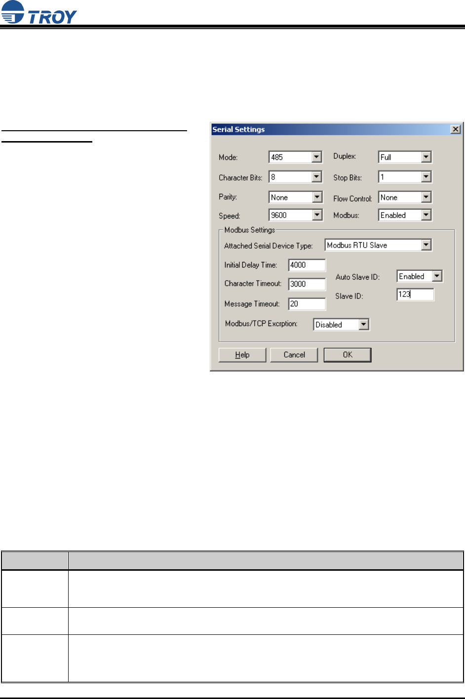
Appendix C: Serial Port Pinouts
TCP Port Connections
The TROY Serial Server supports port connections over TCP/IP using raw TCP ports only. The TCP
ports are allocated as follows:
PORT DESTINATION DEVICE
502 Used for MODBUS communications
3001 RS-232, RS-422, or first RS-485 device in mulitdrop configuration
3002 Second device in RS-485 multidrop configuration
3032 32nd device in RS-485 multidrop configuation
9100 RS-232, RS-422, or first RS-485 device in mulitdrop configuration
9101 Second device in RS-485 multidrop configuration
9131 RS-232, RS-422, or first RS-485 device in mulitdrop configuration
PIN RS-232 (DTE)
1 DCD (Data Carrier Detect) Input
2 RxD (Receive Data) Input
3 TxD (Transmit Data) Output
4 DTR (Data Terminal Ready) Output
5 GND (Signal Ground)
6 DSR (Data Set Ready) Input
7 RTS (Request To Send) Output
8 CTS (Clear To Send) Input
9 RI (Ring) or +5 VDC power input (selectable via 3-pin jumper)
PIN RS-422 and RS-485 (4-wire, full duplex)
2 RD+ (Receive Data +) Differential Input
3 TD+ (Transmit Data +) Differential Output
4 TD – (Transmit Data –) Differential Output
5 GND (Signal Ground)
6 RD – (Receive Data –) Differential Input
9 Optional +5 VDC power input (selectable via a 3-pin jumper)
PIN RS-485 (2-wire, half duplex)
3 TD+/RD+ (Transmit / Receive Data +) Differential Bi-directional
4 TD –/RD – (Transmit / Receive Data –) Differential Bi-directional
5 GND (Signal Ground)
9 Optional +5 VDC power input (selectable via a 3-pin jumper)
Serial Server User’s Guide
Document #40179-120 Rev. X5 D-1
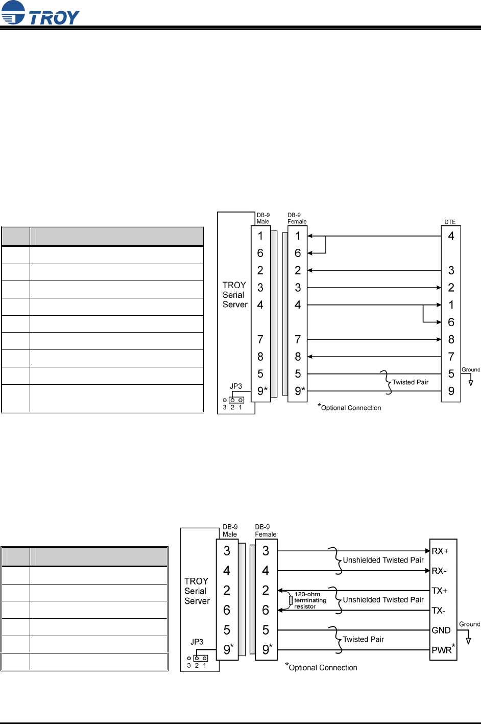
Appendix D: Alternate Power Source Configuration
The TROY Serial Server can be configured to use a +5 VDC input via Pin 9 on the DB-9 connector to
power the unit instead of using the supplied power supply module. To configure the serial server to
accept power via Pin 9, the serial server case must be opened, and the shunt at JP3 must be moved from
Pins 2 and 3 to Pins 1 and 2 (towards the +5 indicator). The voltage measured at Pins 9 and 5 must be at
least +4.8 VDC and not greater then +5.2 VDC. Minimum supply current is 800 mA and 500 mA for the
TROY wireless and non-wireless serial server, respectively. If Pin 9 is utilized for power, it is
recommended that shielded cable be used to minimize EMI (Electro-Magnetic Interference).
RS-232 Port
In RS-232 mode, the DB-9 male connector is configured as a Data Terminal Equipment (DTE) port.
Figure 1 below shows a null-modem cable connection to another DTE device.
Pin Description
1 DCD (Data Carrier Detect) Input
6 DSR (Data Set Ready) Input
2 RxD (Receive Data) Input
3 TxD (Transmit Data) Output
4 DTR (Data Terminal Ready) Output
7 RTS (Request To Send) Output
8 CTS (Clear To Send) Input
5 Ground
9 RI (Ring) Input or +5 VDC Power Input
(Optional)
Figure 1
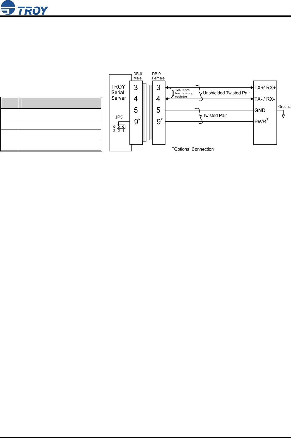
RS-422 / 485 Full Duplex Port
In RS-422 / 485 full duplex mode, the DB-9 male connector is configured as follows. It is important to
construct the cable so that an unshielded twisted pair (UTP) wire is used for the transmit pair and another
UTP wire is used for the receive pair to minimize EMI emissions and maximize immunity to outside
sources (see Figure 2). If the TROY Serial Server is the last device in a chain, then a 120-ohm
terminating resistor should be placed across Pins 2 and 6. The Pin 9 connection is optional.
Figure 2
Pin Description
3 TX+ (Transmit) Output
4 TX– (Transmit) Output
2 RX+ (Receive) Input
6 RX– (Receive) Input
5 Ground
9 +5 VDC Power Input (optional)
Serial Server User’s Guide
Document #40179-120 Rev. X5 D-2
RS-485 Half-Duplex Port
In RS-485 half-duplex mode, the DB-9 male connector is configured as shown below. It is important to
construct the cable so that an unshielded twisted pair (UTP) wire is used for the transmit/receive pair to
minimize EMI emissions and maximize immunity to outside sources (see Figure 3). If the TROY Serial
Server is the last device in a chain, then a 120-ohm terminating resistor should be placed across Pins 3
and 4. The Pin 9 connection is optional.
Figure 3
Pin Description
3 TX+/RX+ (Bi-Directional)
4 TX–/RX– (Bi-Directional)
5 Ground
9 +5 VDC Power Input (optional)
Serial Server User’s Guide
Document #40179-120 Rev. X5 E-1
Appendix E: Loading New Firmware
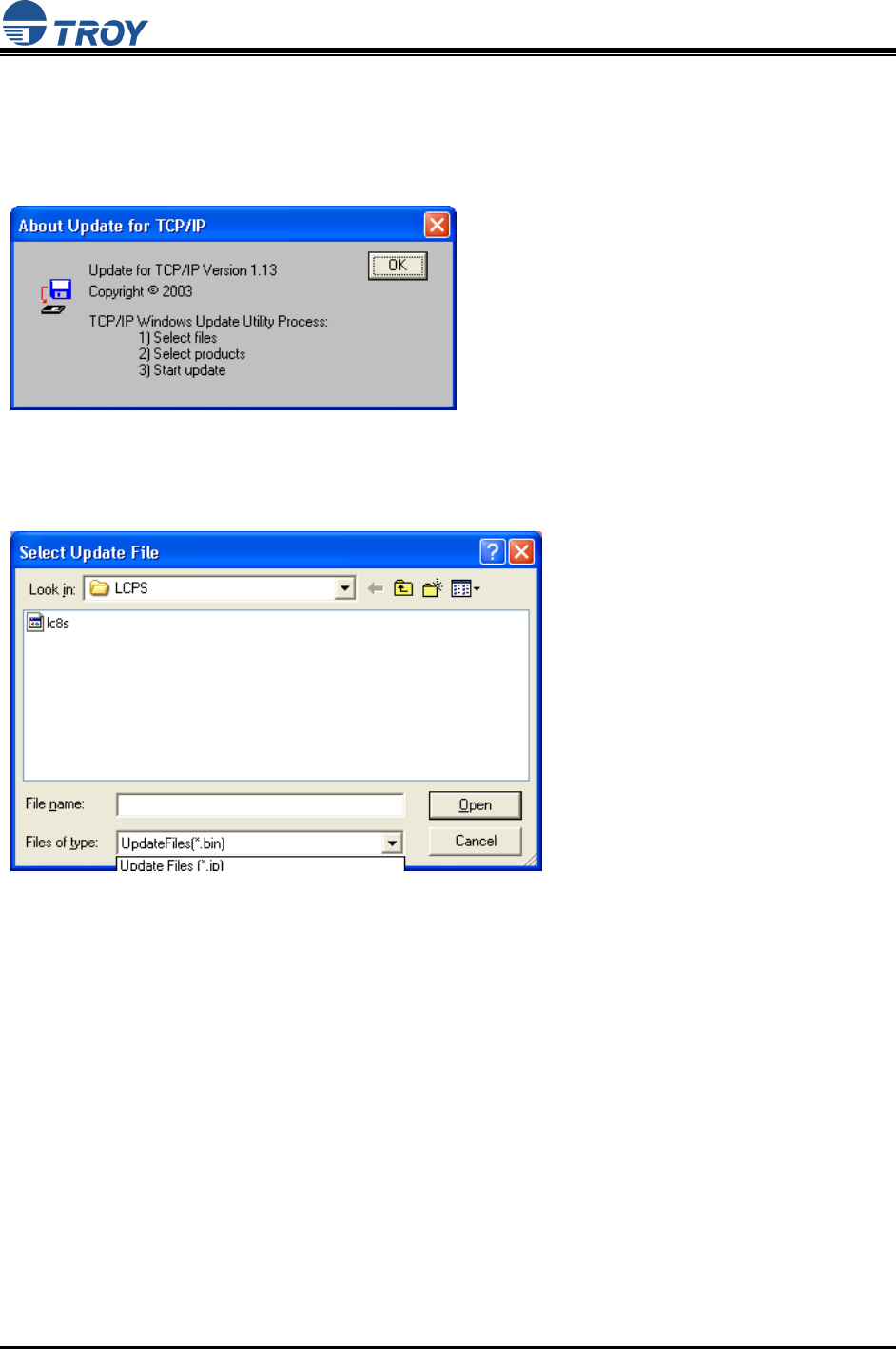
1. Run the TROY Wireless Update utility for TCP/IP. The About Update for TCP/IP window will be
displayed. Click on OK to continue. The Select Update File window will be displayed.
2. Select UpdateFiles (*.bin) file type, locate the Serial Server bin file, and then click on Open. A
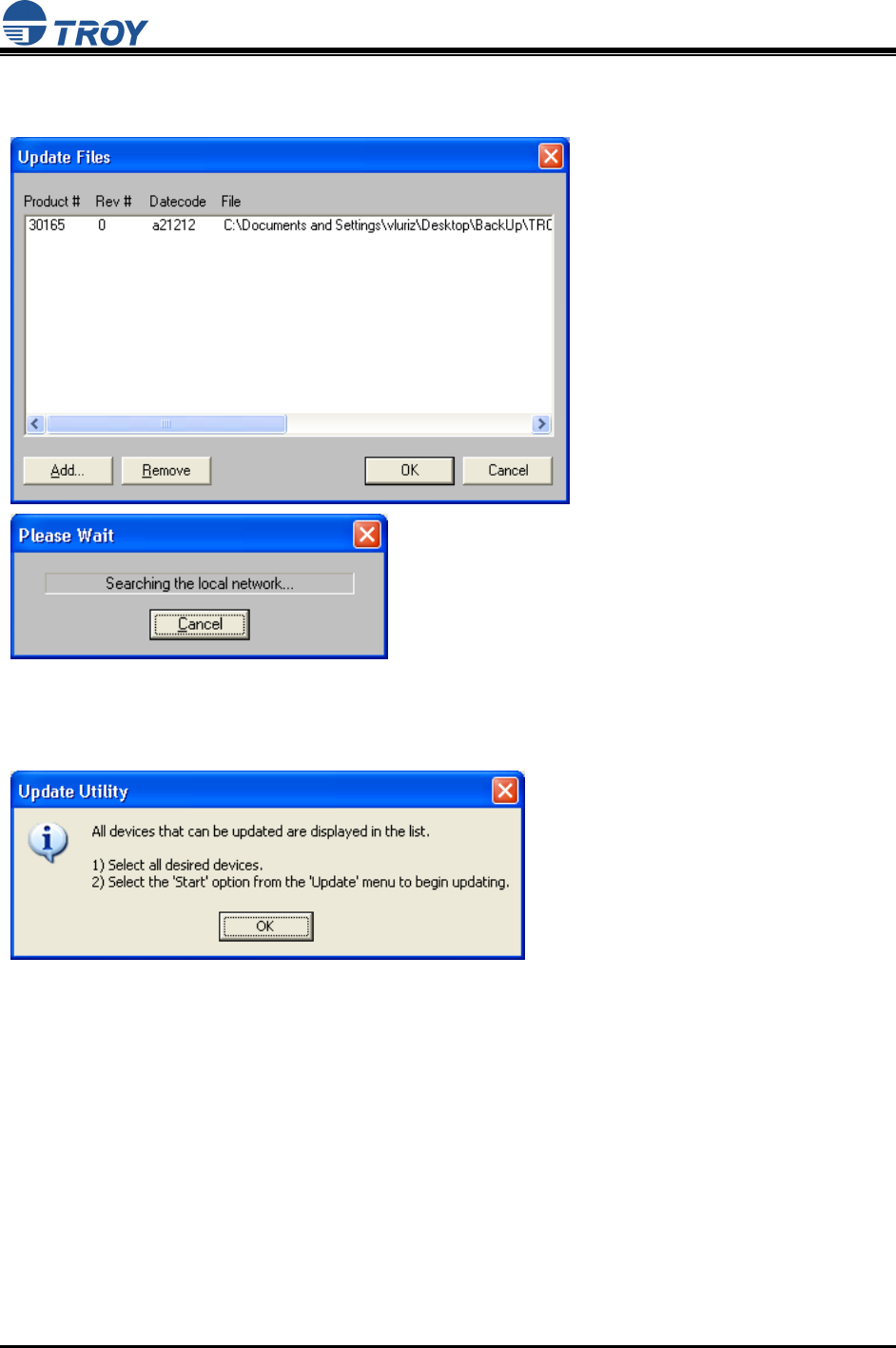
window will be displayed (see next page) showing the file(s) you have selected including the revision
level and date code for each file.
Serial Server User’s Guide
Document #40179-120 Rev. X5 E-2
3. Verify that the file(s) are correct, and click on OK. The utility will begin searching for qualified serial
servers present on the network.
4. When the search process is complete, click on OK to continue. A list of found devices will be
displayed.
Serial Server User’s Guide
Document #40179-120 Rev. X5 E-3
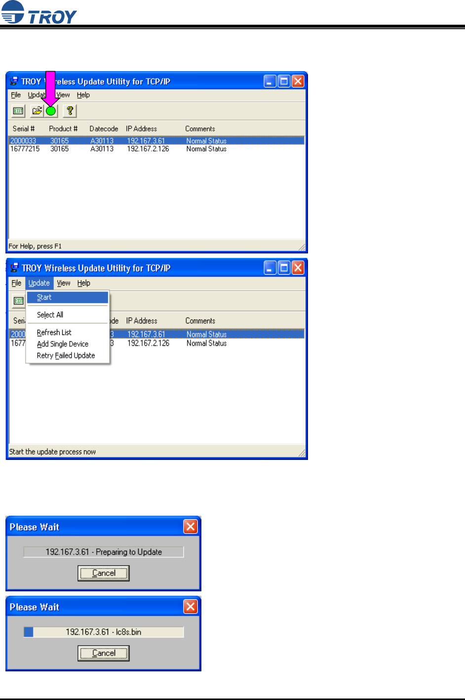
5. Select the desired Serial Server to be upgraded, click on the green icon, or click on UPDATE
Æ
START. The firmware update process will begin automatically as soon as the Serial Server is ready.
6. When the Serial Server is ready, the firmware upgrade will begin. The IP address of the serial server
as well as the file you are loading will be displayed.
Serial Server User’s Guide
Document #40179-120 Rev. X5 E-4
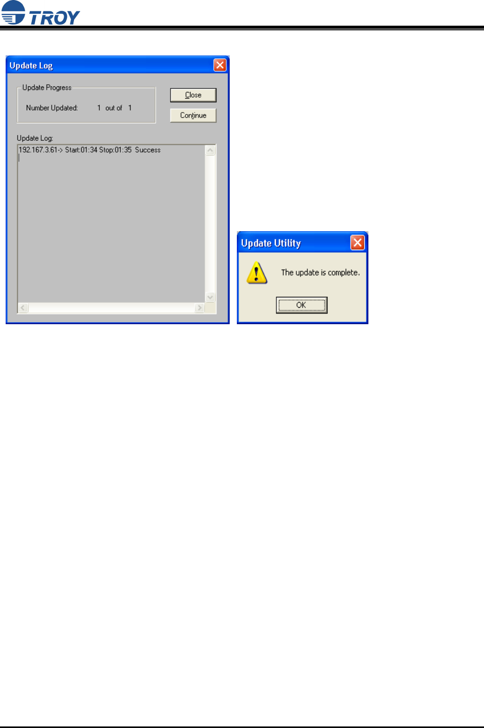
7. The update log will be displayed when the update process is finished. Click on Close to continue.