Silicon Controls SC414002 GASLOG Cellular Dialer User Manual ML000043 docx
Silicon Controls Pty Ltd GASLOG Cellular Dialer ML000043 docx
User Manual

Suite 2, Level1; 12 Waterloo Road
Macquarie Park NSW 2113 Australia
(ACN 054 993 529)
Phone +61 2 8877 6060
Fax +61 2 8877 6099
Document: ML000043 rev 3
2013
Silicon Controls Pty Ltd All Rights Reserved
SC414
Silicon Controls Pty Ltd All Rights Reserved
SC414
Cellular Dialer
User Manual
Date: 2013-09-02
Document: ML000043 rev 3
© 2013 Silicon Controls Pty Ltd All Rights
Reserved
Disclaimer
All material contained in this document is furnished
Licence ("Licence") and/or a duly executed Agreement to Purchase or Lease Equipment ("Agreement") and/or a duly
executed Non-
Disclosure Agreement (“NDA”). All terms, conditions, warranties, un
representations, whether express, implied, statutory or otherwise, relating in any way to the products the subject of
the Licence and/or the Agreement and/or the NDA are excluded, other than:
1. terms, conditions or warranties
expressly provided for in the Licence and/or the Agreement and/or the NDA; and
2.
terms, conditions or warranties implied by any Act of Parliament which may not be excluded
provided that the liability of Silicon Controls Pty Ltd for any breach of any such ter
subject to the Licence and/or Agreement, be limited at the option of Silicon Controls Pty Ltd to any one or more of the
following:
(a) if the breach relates to goods:
(i)
the replacement of the goods or the supply of the equivalent
(ii)
the repair of the goods;
(iii)
the payment of the cost of replacing the goods or of acquiring equivalent goods; or
(iv)
the payment of the costs of having the goods repaired; and
(b)
if the breach relates to services:
(i)
the supplying of the services again; or
(ii) the pa
yment of the cost of having the services supplied again.
Without limiting the generality hereof, Silicon Controls Pty Ltd shall not be under any liability to any person in respect
of any loss or damage, including consequential loss or damage and however ca
incurred or which may arise directly or indirectly from the use of the material contained in this document or any other
material furnished pursuant to the Licence and/or the Agreement and/or the NDA.
All the users of the mate
rial contained in this document or any other material furnished pursuant to the Licence and/or
the Agreement and/or the NDA should ensure that the material is used in compliance with the laws, rules and
regulations of the jurisdictions in which the materia
without notice and Silicon Controls Pty Ltd may issue revised documents containing any such changes.
Change History
Revision Date
Description of Change
1 2009-12-02
Release for FCC Certification
2 2013-08-07
Revised corporate address.
Added RF Exposure information
3 2013-09-02
Clarified model numbering in
response to TCB query.
Reserved
All material contained in this document is furnished
pursuant to the terms and conditions of a duly executed Product
Licence ("Licence") and/or a duly executed Agreement to Purchase or Lease Equipment ("Agreement") and/or a duly
Disclosure Agreement (“NDA”). All terms, conditions, warranties, un
dertakings, inducements or
representations, whether express, implied, statutory or otherwise, relating in any way to the products the subject of
the Licence and/or the Agreement and/or the NDA are excluded, other than:
expressly provided for in the Licence and/or the Agreement and/or the NDA; and
terms, conditions or warranties implied by any Act of Parliament which may not be excluded
provided that the liability of Silicon Controls Pty Ltd for any breach of any such ter
m, condition or warranty shall,
subject to the Licence and/or Agreement, be limited at the option of Silicon Controls Pty Ltd to any one or more of the
the replacement of the goods or the supply of the equivalent
goods;
the repair of the goods;
the payment of the cost of replacing the goods or of acquiring equivalent goods; or
the payment of the costs of having the goods repaired; and
if the breach relates to services:
the supplying of the services again; or
yment of the cost of having the services supplied again.
Without limiting the generality hereof, Silicon Controls Pty Ltd shall not be under any liability to any person in respect
of any loss or damage, including consequential loss or damage and however ca
used, which may be suffered or
incurred or which may arise directly or indirectly from the use of the material contained in this document or any other
material furnished pursuant to the Licence and/or the Agreement and/or the NDA.
rial contained in this document or any other material furnished pursuant to the Licence and/or
the Agreement and/or the NDA should ensure that the material is used in compliance with the laws, rules and
regulations of the jurisdictions in which the materia
l is used. The material contained within is subject to change
without notice and Silicon Controls Pty Ltd may issue revised documents containing any such changes.
Description of Change
Prepared By
Release for FCC Certification
JH
Revised corporate address.
Added RF Exposure information
JH
Clarified model numbering in
response to TCB query.
JH
Page 1 of 7
pursuant to the terms and conditions of a duly executed Product
Licence ("Licence") and/or a duly executed Agreement to Purchase or Lease Equipment ("Agreement") and/or a duly
dertakings, inducements or
representations, whether express, implied, statutory or otherwise, relating in any way to the products the subject of
expressly provided for in the Licence and/or the Agreement and/or the NDA; and
terms, conditions or warranties implied by any Act of Parliament which may not be excluded
m, condition or warranty shall,
subject to the Licence and/or Agreement, be limited at the option of Silicon Controls Pty Ltd to any one or more of the
the payment of the cost of replacing the goods or of acquiring equivalent goods; or
Without limiting the generality hereof, Silicon Controls Pty Ltd shall not be under any liability to any person in respect
used, which may be suffered or
incurred or which may arise directly or indirectly from the use of the material contained in this document or any other
rial contained in this document or any other material furnished pursuant to the Licence and/or
the Agreement and/or the NDA should ensure that the material is used in compliance with the laws, rules and
l is used. The material contained within is subject to change
without notice and Silicon Controls Pty Ltd may issue revised documents containing any such changes.
Approved By
MN
MN
MN
Document: ML000043 rev 3
© 2013 Silicon Controls Pty Ltd All Rights
Reserved
1 OVERVIEW
1.1 GASLOG System
The GASLOG System is a telemetry system designed to provide continuous monitoring of gas tank
installations. Tank
level, meter reading, and other status information is transferred from the remote site to
the enterprise database according to a defined reporting schedule.
Sites communicate with a Server using the mobile telephone network
on model)
. The Server stores the site information in an industry standard SQL database that can easily
be integrated into other processes in the supply chain.
The GASLOG system is highly scalable and capable of handling hundreds of thousands of customers,
sites and tanks.
1.2 GASLOG
Model Numbering
SC414anrst – Cellular Dialer
a = A = ANZ (IECEx)
n =
6 = 868Mhz Long Range Type 2
r =
3 = GSM 900/1800
6 = GSM + UMTS/HSPA
s =
t =
1 = 2G GSM Type 1
4 = 1xRTT CDMA Type 1
Reserved
The GASLOG System is a telemetry system designed to provide continuous monitoring of gas tank
level, meter reading, and other status information is transferred from the remote site to
the enterprise database according to a defined reporting schedule.
Sites communicate with a Server using the mobile telephone network
(GSM/GPRS or CDMA, depending
. The Server stores the site information in an industry standard SQL database that can easily
be integrated into other processes in the supply chain.
The GASLOG system is highly scalable and capable of handling hundreds of thousands of customers,
GASLOG System Architecture
Model Numbering
B = EEC (ATEX)
6 = 868Mhz Long Range Type 2
7 = 916Mhz Long Range Type 2
4 = GSM 850/1900
5 = GSM 850/900/1800/1900
6 = GSM + UMTS/HSPA
7 = 1xRTT CDMA
8 = 1xRTT + EVDO CDMA
1 = 2 x Universal Input (3V)
1 = 2G GSM Type 1
2 = 2G GSM Type 2
4 = 1xRTT CDMA Type 1
5 = 1xRTT + EVDO CDMA Type 1
Page 2 of 7
The GASLOG System is a telemetry system designed to provide continuous monitoring of gas tank
level, meter reading, and other status information is transferred from the remote site to
(GSM/GPRS or CDMA, depending
. The Server stores the site information in an industry standard SQL database that can easily
The GASLOG system is highly scalable and capable of handling hundreds of thousands of customers,
C = USA (AEx)
7 = 916Mhz Long Range Type 2
5 = GSM 850/900/1800/1900
8 = 1xRTT + EVDO CDMA
3 = 3G GSM Type 1

Document: ML000043 rev 3
© 2013 Silicon Controls Pty Ltd All Rights
Reserved
1.3
GASLOG Site Equipment
Each GASLOG cellular site consists of two primary components:
SC414 Cellular Dialer. Connect
s
cellular network.
Sensor(s).
Senders provide locally wired tank level
Reserved
GASLOG Site Equipment
Each GASLOG cellular site consists of two primary components:
s
to sensors and performs
data logging and Server communications via a
Senders provide locally wired tank level
information for the SC414
Cellular Dialer.
Page 3 of 7
data logging and Server communications via a
Cellular Dialer.

Document: ML000043 rev 3
© 2013 Silicon Controls Pty Ltd All Rights
Reserved
2
SC414 CELLULAR DIALER INSTALLATION
NOTE: This product should only be installed by qualified personnel.
2.1 Overview
The SC414 Cellular Dialer is specifically designed
float gauges, eliminating the need for expensive intrinsic safety barriers and wiring to the tank.
SC414 periodically communicates with the GASLOG Server via a cellular network, transferring all the
recorded tank level and gas usage data to the Server.
2.2 Location
The location of the Dialer is a prime consideration.
Not close to pipes, metalwork or other solid obstacles (other than the body of the tank upon which it is
mounted).
As high off the ground
as possible.
The location should minimise the chance of the Dialer being subject to physical shock or vibration.
NOTE:
The cellular network signal strength is often improved by mounting the Dialer higher
or further away from metal objects.
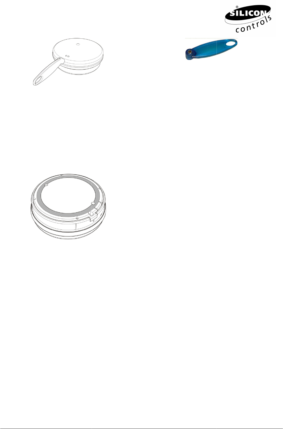
2.3 Install Sender(s)
The Dialer comes with a mounting bracket attached to ease
bracket using an SC663A Removal Tool.
The underside of the Dialer contains two Field Sensor interface connectors and
Plug the cable from the S
ender to one of the Field connectors.
2.4 Activation
To install the Dialer
the SC414 needs to be manually activated from its normal power down state.
done using the SC664A Activation Tool.
shown in the figure below.
When
Reserved
SC414 CELLULAR DIALER INSTALLATION
NOTE: This product should only be installed by qualified personnel.
The SC414 Cellular Dialer is specifically designed
to mount on LP-
Gas tanks and connect to existing tank
float gauges, eliminating the need for expensive intrinsic safety barriers and wiring to the tank.
SC414 periodically communicates with the GASLOG Server via a cellular network, transferring all the
recorded tank level and gas usage data to the Server.
The location of the Dialer is a prime consideration.
Not close to pipes, metalwork or other solid obstacles (other than the body of the tank upon which it is
as possible.
The location should minimise the chance of the Dialer being subject to physical shock or vibration.
The cellular network signal strength is often improved by mounting the Dialer higher
or further away from metal objects.
The Dialer comes with a mounting bracket attached to ease
fixing of the Dialer in place
bracket using an SC663A Removal Tool.
Detaching the mounting bracket
The underside of the Dialer contains two Field Sensor interface connectors and
the battery compartment.
ender to one of the Field connectors.
the SC414 needs to be manually activated from its normal power down state.
done using the SC664A Activation Tool.
The
activation point is on the side of the case near the LEDs, as
When
the
Activation Tool is sensed by the SC414 the red LED will illuminate.
Page 4 of 7
Gas tanks and connect to existing tank
float gauges, eliminating the need for expensive intrinsic safety barriers and wiring to the tank.
The
SC414 periodically communicates with the GASLOG Server via a cellular network, transferring all the
Not close to pipes, metalwork or other solid obstacles (other than the body of the tank upon which it is
The location should minimise the chance of the Dialer being subject to physical shock or vibration.
The cellular network signal strength is often improved by mounting the Dialer higher
fixing of the Dialer in place
. Detach the
the battery compartment.
the SC414 needs to be manually activated from its normal power down state.
This is
activation point is on the side of the case near the LEDs, as
Activation Tool is sensed by the SC414 the red LED will illuminate.
Document: ML000043 rev 3
© 2013 Silicon Controls Pty Ltd All Rights
Reserved
SC414 Activation
The SC414 will retrieve its operational
Configuration parameters are verified by the GASLOG database and may be queried using the GASLOG
Explorer or EAGLE software tools.
2.5 Mounting
a Dialer to a Tank
Re-attach th
e mounting bracket to the Dialer.
Turn the Dialer upside down and apply adhesive to its base.
Turn the Dialer upright and press it lightly down onto the tank s
Maintain the Dialer in position until the adhesive cures
2.6
Mounting a Dialer (Screw Method)
NOTE: Do not screw into a tank!
The mounting bracket incorporates moulded features, in the form of bosses and break
the location of mounting screws.
Choose a self tapping
screw appropriate for the material that the structure is made from.
Hold the mounting bracket
against
structure.
With the bracket secured in plac
SC414 case and pressing the SC414 onto the bracket until the latch
Reserved
SC664A Activation Tool
The SC414 will retrieve its operational
parameters from the GASLOG database during its initial activation.
Configuration parameters are verified by the GASLOG database and may be queried using the GASLOG
Explorer or EAGLE software tools.
a Dialer to a Tank
(Adhesive Method)
e mounting bracket to the Dialer.
Turn the Dialer upside down and apply adhesive to its base.
The mounting bracket has a defined channel
moulded in,
along which adhesive may be
dispensed.
Turn the Dialer upright and press it lightly down onto the tank s
urface.
Maintain the Dialer in position until the adhesive cures
Mounting a Dialer (Screw Method)
The mounting bracket incorporates moulded features, in the form of bosses and break
screw appropriate for the material that the structure is made from.
against
the locating surface and, screw through the
break
With the bracket secured in plac
e, a
ttach the Dialer by locating the bracket’s latching features into the
SC414 case and pressing the SC414 onto the bracket until the latch
audibly “
clicks
Page 5 of 7
SC664A Activation Tool
parameters from the GASLOG database during its initial activation.
Configuration parameters are verified by the GASLOG database and may be queried using the GASLOG
The mounting bracket has a defined channel
along which adhesive may be
The mounting bracket incorporates moulded features, in the form of bosses and break
-out holes, to aid
screw appropriate for the material that the structure is made from.
break
-out hole and into the
ttach the Dialer by locating the bracket’s latching features into the
clicks
” into place.

Document: ML000043 rev 3
© 2013 Silicon Controls Pty Ltd All Rights
Reserved
3
MAINTAINING THE
3.1 Inspection and C
leaning
The following should be
inspected every time the tank is filled:
Housing is clean and has no cracks or significant abrasions
Mounting plate is securely fastened to the mounting surface
Outer sheath of the sensor cable(s) are not damaged
Sensor(s) and Meter(s)
are properly fitted
WARNING: Potential electrostatic charging hazard:
Clean housing with damp cloth only to avoid static discharge
Do not use solvents
3.2 Battery Replacement
If the battery needs replacement, it must only be replaced with an approved cell typ
Controls for approved battery specifications (refer to document SP000017).
publication TN00007 for the battery replacement procedure.
Reserved
MAINTAINING THE
SC414
CELLULAR DIALER
leaning
inspected every time the tank is filled:
Housing is clean and has no cracks or significant abrasions
Mounting plate is securely fastened to the mounting surface
Outer sheath of the sensor cable(s) are not damaged
are properly fitted
and fixed in place
WARNING: Potential electrostatic charging hazard:
Clean housing with damp cloth only to avoid static discharge
If the battery needs replacement, it must only be replaced with an approved cell typ
Controls for approved battery specifications (refer to document SP000017).
Refer to Silicon Controls’
publication TN00007 for the battery replacement procedure.
Page 6 of 7
CELLULAR DIALER
If the battery needs replacement, it must only be replaced with an approved cell typ
e. Contact Silicon
Refer to Silicon Controls’

Document: ML000043 rev 3
© 2013 Silicon Controls Pty Ltd All Rights
Reserved
4 FCC
PART 15 COMPLIANCE
GASLOG equipment has been tested and found to comply
subject to the following two conditions: (1) This device may not cause harmful interference, and (2) this
device must accept any interference received, i
This equipment has been tested and found to comply with the limits for a Class B digital device, pursuant to
part 15 of the FCC Rules. These limits are designed to provide reasonable protection
interference in a residential installation.
GASLOG equipment generates, uses and can radiate radio frequency energy and, if not installed and used
in
accordance with the installation manual, may cause harmful interfere
However, there is no guarantee that interference will not occu
does cause harmful interference to radio or television reception, which can be determined by turning the
equipment off and on, the user
may try to correct the interference by one or more of the following:
o
Reorient or relocate the receiving antenna of the radio or television.
o
Increase the separation between the equipment and the receiver.
o
Connect the equipment onto an outlet on a different
o
Consult the dealer or an experienced radio/TV technician.
The user may find the following booklet helpful:
o
How to Identify and Resolve Radio
This booklet is available from the US Governmen
WARNING: changes or modifications to GASLOG equipment not expressly approved by Silicon Controls
could void the user's authority to operate the equipment.
4.1
RF Exposure Information
This device meets the government’
s
This device is designed and manufactured not to exceed the emission limits for exposure to radio frequency
(RF) energy set by the Federal Communications Commission of the U.S. Government.
This device complies with
FCC radiation exposure limits set forth for an uncontrolled environment. In order to
avoid the possibility of exceeding the FCC radio frequency exposure limits, human proximity to the antenna
shall not be less than 20cm (8 inches) during normal operation.
The antenna(s) used for this transmitter must not be co
antenna or transmitter.
Reserved
PART 15 COMPLIANCE
GASLOG equipment has been tested and found to comply
with part 15 of the FCC Rules. Operation is
subject to the following two conditions: (1) This device may not cause harmful interference, and (2) this
device must accept any interference received, i
ncluding interference that may cause undesired operation.
This equipment has been tested and found to comply with the limits for a Class B digital device, pursuant to
part 15 of the FCC Rules. These limits are designed to provide reasonable protection
interference in a residential installation.
GASLOG equipment generates, uses and can radiate radio frequency energy and, if not installed and used
accordance with the installation manual, may cause harmful interfere
nce with radio communi
However, there is no guarantee that interference will not occu
r in a particular installation.
does cause harmful interference to radio or television reception, which can be determined by turning the
may try to correct the interference by one or more of the following:
Reorient or relocate the receiving antenna of the radio or television.
Increase the separation between the equipment and the receiver.
Connect the equipment onto an outlet on a different
branch circuit than that of the receiver.
Consult the dealer or an experienced radio/TV technician.
The user may find the following booklet helpful:
How to Identify and Resolve Radio
-TV Interference Problems
This booklet is available from the US Governmen
t Printing Office, Washington, D.C. 20402.
WARNING: changes or modifications to GASLOG equipment not expressly approved by Silicon Controls
could void the user's authority to operate the equipment.
RF Exposure Information
s
requirements for exposure to radio waves.
This device is designed and manufactured not to exceed the emission limits for exposure to radio frequency
(RF) energy set by the Federal Communications Commission of the U.S. Government.
FCC radiation exposure limits set forth for an uncontrolled environment. In order to
avoid the possibility of exceeding the FCC radio frequency exposure limits, human proximity to the antenna
shall not be less than 20cm (8 inches) during normal operation.
The antenna(s) used for this transmitter must not be co
-
located or operating in conjunction with any other
Page 7 of 7
with part 15 of the FCC Rules. Operation is
subject to the following two conditions: (1) This device may not cause harmful interference, and (2) this
ncluding interference that may cause undesired operation.
This equipment has been tested and found to comply with the limits for a Class B digital device, pursuant to
part 15 of the FCC Rules. These limits are designed to provide reasonable protection
against harmful
GASLOG equipment generates, uses and can radiate radio frequency energy and, if not installed and used
nce with radio communi
cations.
r in a particular installation.
If this equipment
does cause harmful interference to radio or television reception, which can be determined by turning the
may try to correct the interference by one or more of the following:
branch circuit than that of the receiver.
t Printing Office, Washington, D.C. 20402.
WARNING: changes or modifications to GASLOG equipment not expressly approved by Silicon Controls
This device is designed and manufactured not to exceed the emission limits for exposure to radio frequency
(RF) energy set by the Federal Communications Commission of the U.S. Government.
FCC radiation exposure limits set forth for an uncontrolled environment. In order to
avoid the possibility of exceeding the FCC radio frequency exposure limits, human proximity to the antenna
located or operating in conjunction with any other