Silicon Laboratories Finland BGM111 Blue Gecko BGM111 Bluetooth Smart Module User Manual
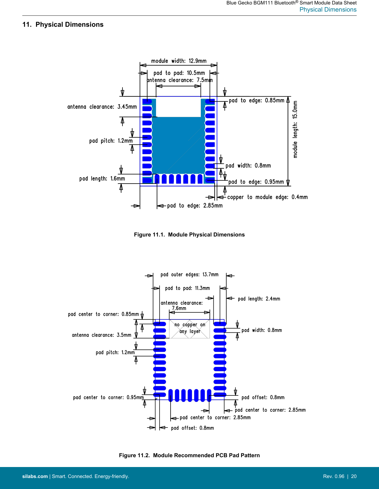
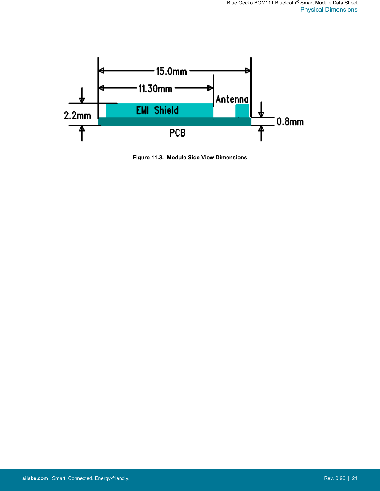
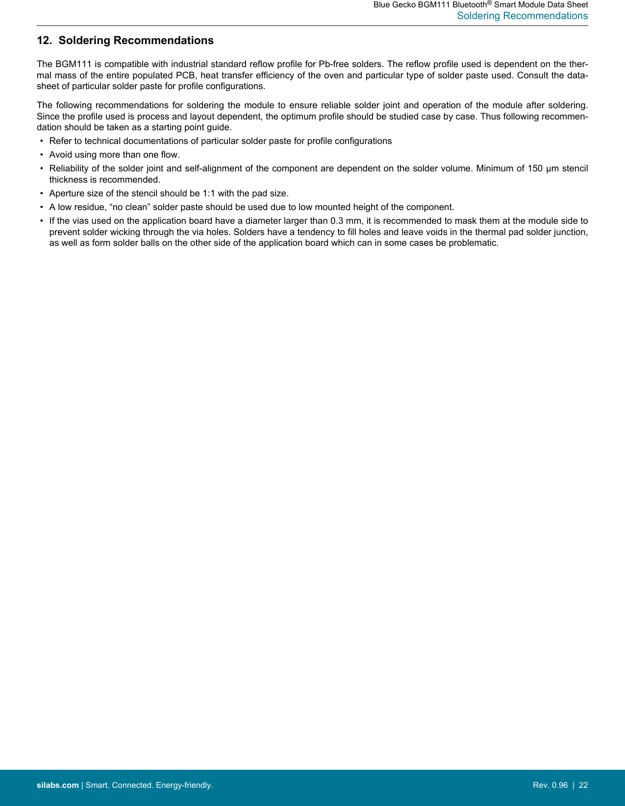
Silicon Laboratories Finland Oy Blue Gecko BGM111 Bluetooth Smart Module
UserManual.wiki
>
Silicon Laboratories Finland
>
BGM111 User Manual
>
User Manual
Contents
1.
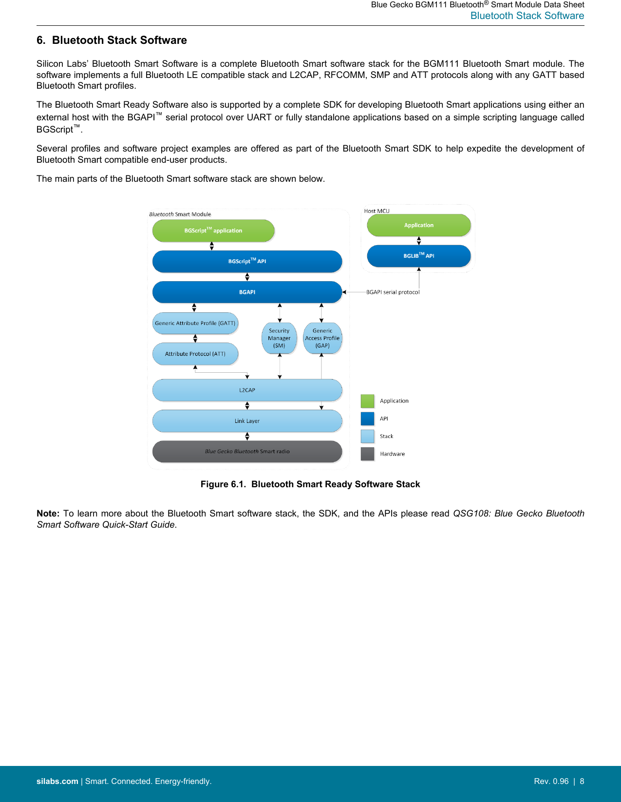
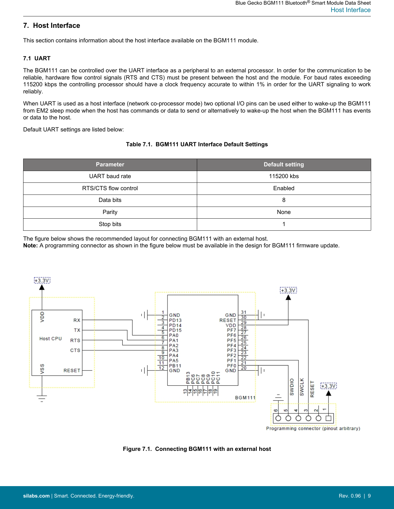
User Manual
2.
Installation Guide
User Manual
Navigation menu
Upload a User Manual
Namespaces
Wiki Guide
HTML
PDF
Info
Views
User Manual
Discussion / Help
Navigation