Silicon Laboratories Finland EM35XB ETRX3 Series Long Range Modules User Manual ETRX357 LR Product Manual
Telegesis (UK) Ltd ETRX3 Series Long Range Modules ETRX357 LR Product Manual
UserManual.wiki
>
Silicon Laboratories Finland
>
EM35XB User Manual
>
Manual
Contents
1.
Manual
2.
User Manual
Manual
Navigation menu
Upload a User Manual
Namespaces
Wiki Guide
HTML
PDF
Info
Views
User Manual
Discussion / Help
Navigation
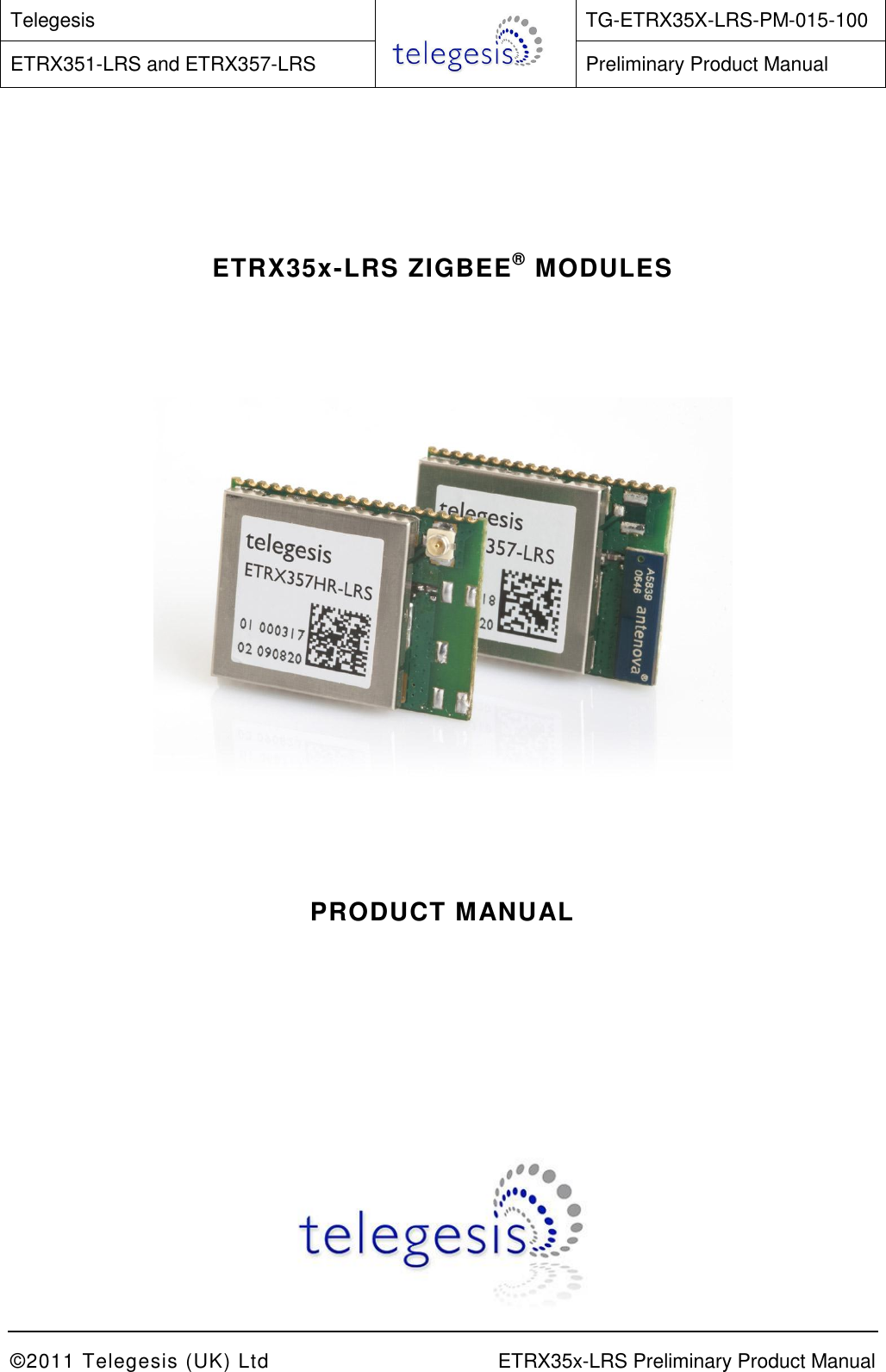
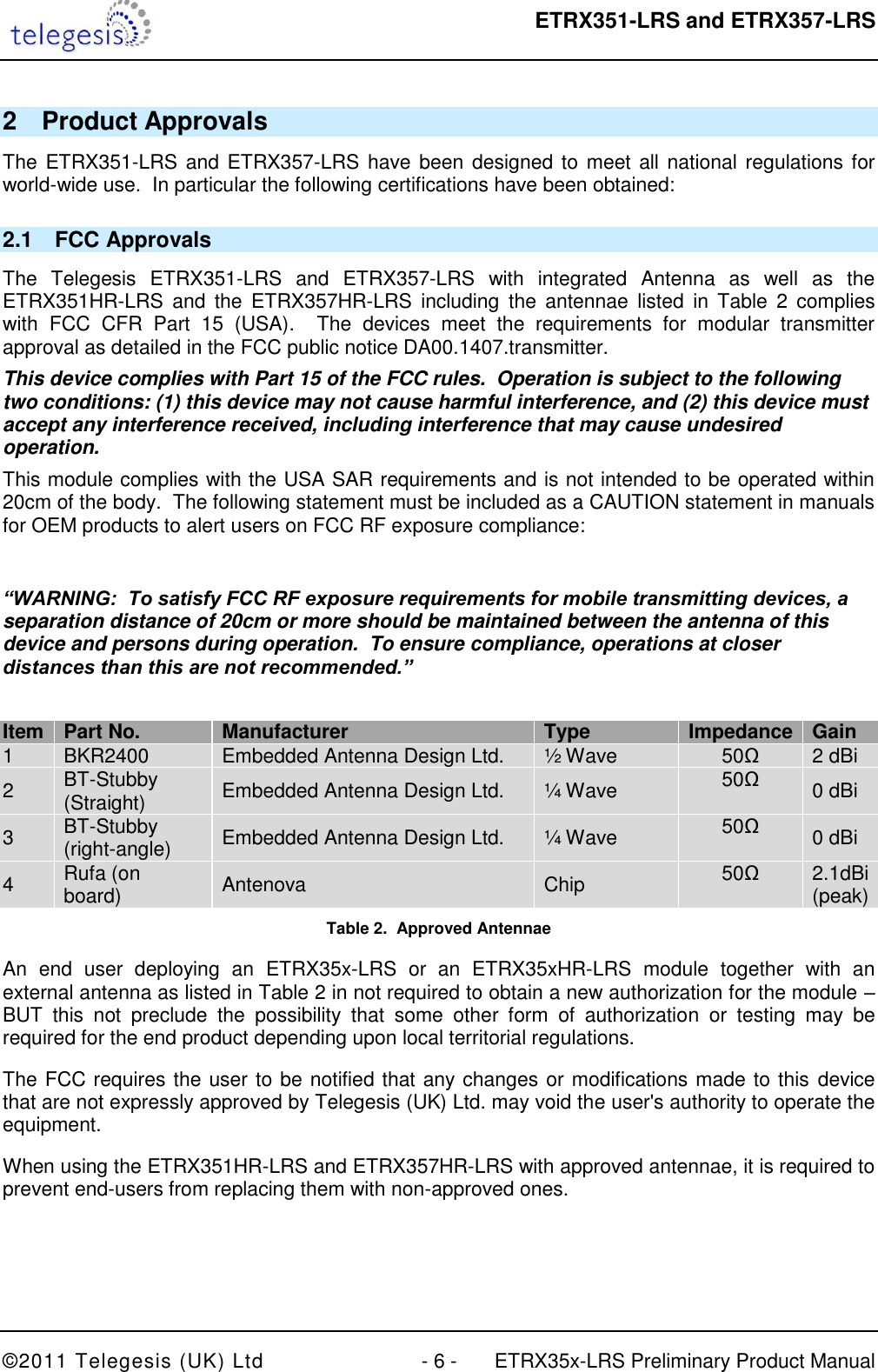
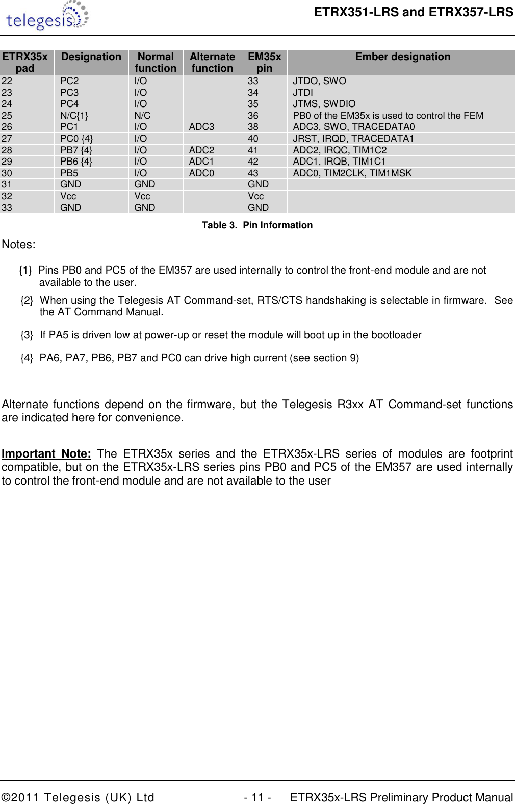
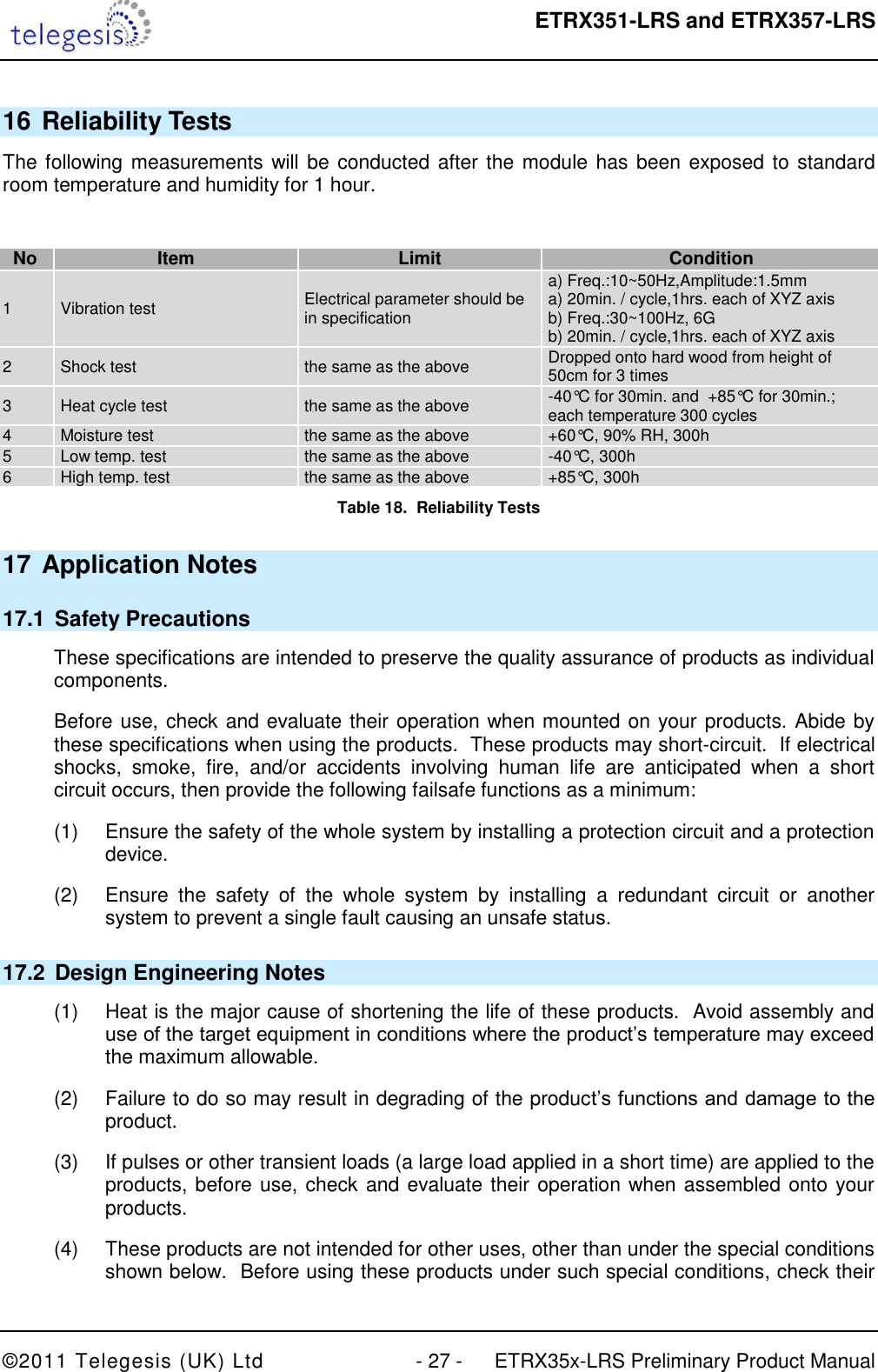
![ETRX351-LRS and ETRX357-LRS ©2011 Telegesis (UK) Ltd - 5 - ETRX35x-LRS Preliminary Product Manual 1 Introduction This document describes the Telegesis ETRX351-LRS and ETRX357-LRS ZigBee® long range modules which have been designed to be easily integrated into another device and to provide a fast, simple and low cost wireless mesh networking interface. The Telegesis ETRX3 series modules are based on the Ember ZigBee® platform consisting of the single chip EM351 or EM357 combined with the ZigBee PRO compliant EmberZNet meshing stack. Integration into a wide range of applications is made easy using a simple AT style command interface and advanced hardware design. The configurable functionality of the Telegesis AT Commandset often allows the ETRX3 series ZigBee modules to be used without an additional host microcontroller saving even more integration time and costs. In addition to the Telegesis AT Commandset, the ETRX351-LRS and ETRX357-LRS modules can be used with custom-built firmware and they represent an ideal platform for custom firmware development in conjunction with the Ember development kits. The ETRX3 series shares the same R3xx Telegesis firmware as the ETRX2 and the two devices can be used in the same network. No RF experience or expertise is required to add this powerful wireless networking capability to your products. The ETRX351-LRS and ETRX357-LRS offer fast integration opportunities and the shortest possible time to market for your product. 1.1 Hardware Description The main building blocks of the ETRX351-LRS and ETRX357-LRS are the single chip EM351 and EM357 from Ember, a frontend module combining a Power Amplifier as well as a Low Noise Amplifier, a 24MHz reference crystal and RF front-end circuitry optimized for best RF performance. The modules are available with on-board antenna or alternatively a U.FL connector for attaching external antennae. Modules with the U.FL connector are identified by the “HR” suffix. The LNA and RF power amplifier of the LRS devices improve the output power by 12dB and the sensitivity by 5dB which will increase the range by approximately 700% relative to the standard devices (where local regulations permit the use of the maximum output power). The integrated antenna is an Antenova Rufa, and details of the radiation pattern etc are available from the Antenova website [5]. Module Chip Flash RAM ETRX351-LRS EM351 128kB 12kB ETRX351HR-LRS EM351 128kB 12kB ETRX357-LRS EM357 192kB 12kB ETRX357HR-LRS EM357 192kB 12kB Table 1: Memories The ETRX351-LRS and ETRX357-LRS are used for ZigBee® (www.zigbee.org) applications. If you wish to create your own custom firmware, and not use the pre-loaded Telegesis AT-Command interface, you will need the InSight toolchain, consisting of InSight Desktop™ together with a comprehensive integrated development environment (IDE) and C-language compiler toolchain from Ember. The Ember development environment is not suitable for an 802.15.4-only application that does not use the ZigBee layer.](https://usermanual.wiki/Silicon-Laboratories-Finland/EM35XB.Manual/User-Guide-1411762-Page-5.png)
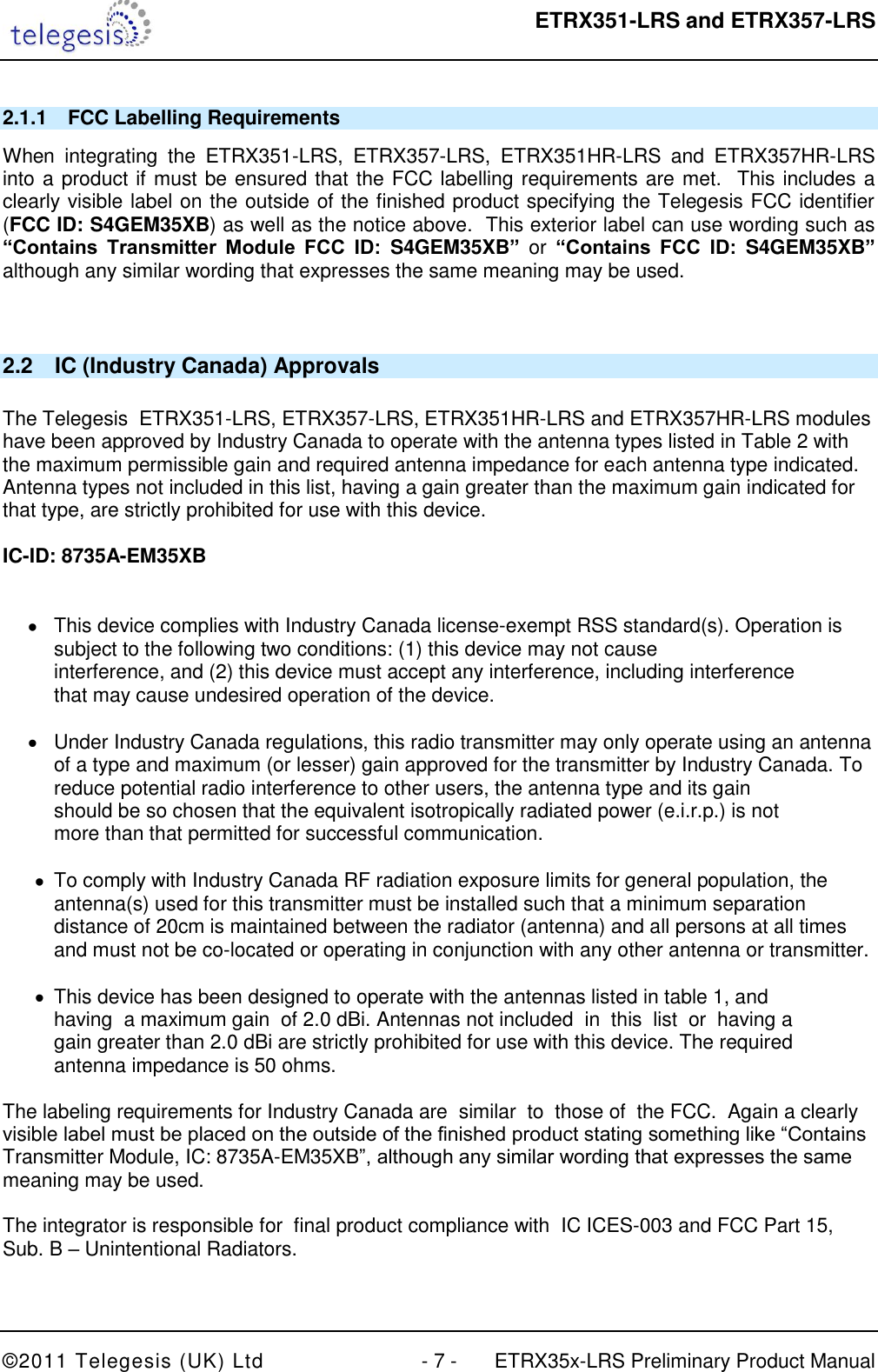
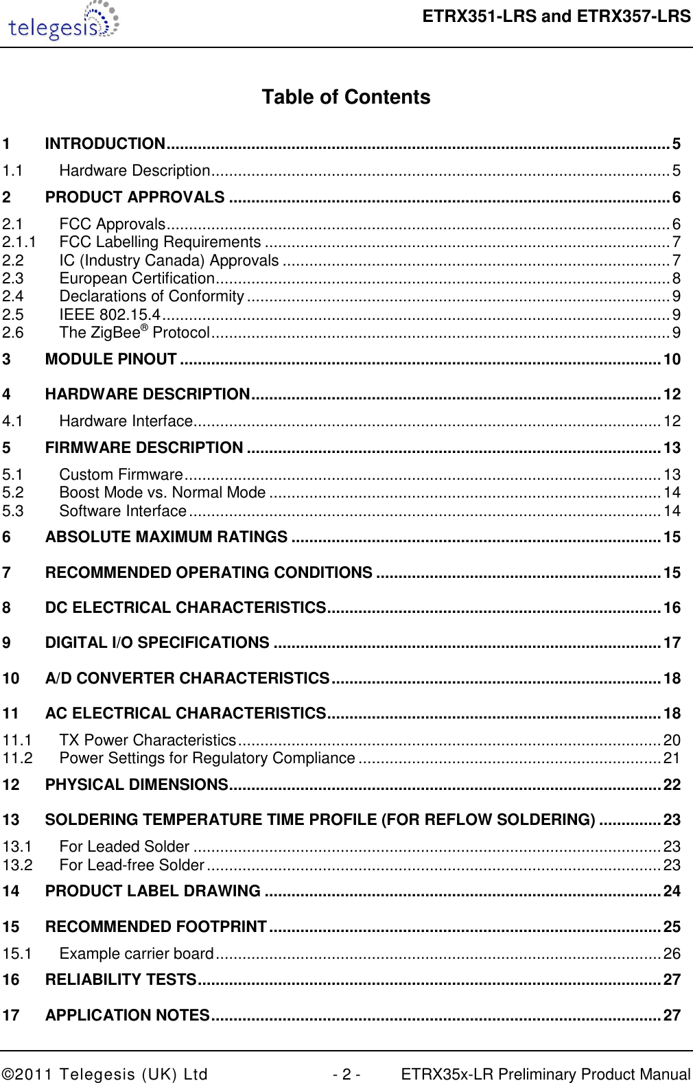
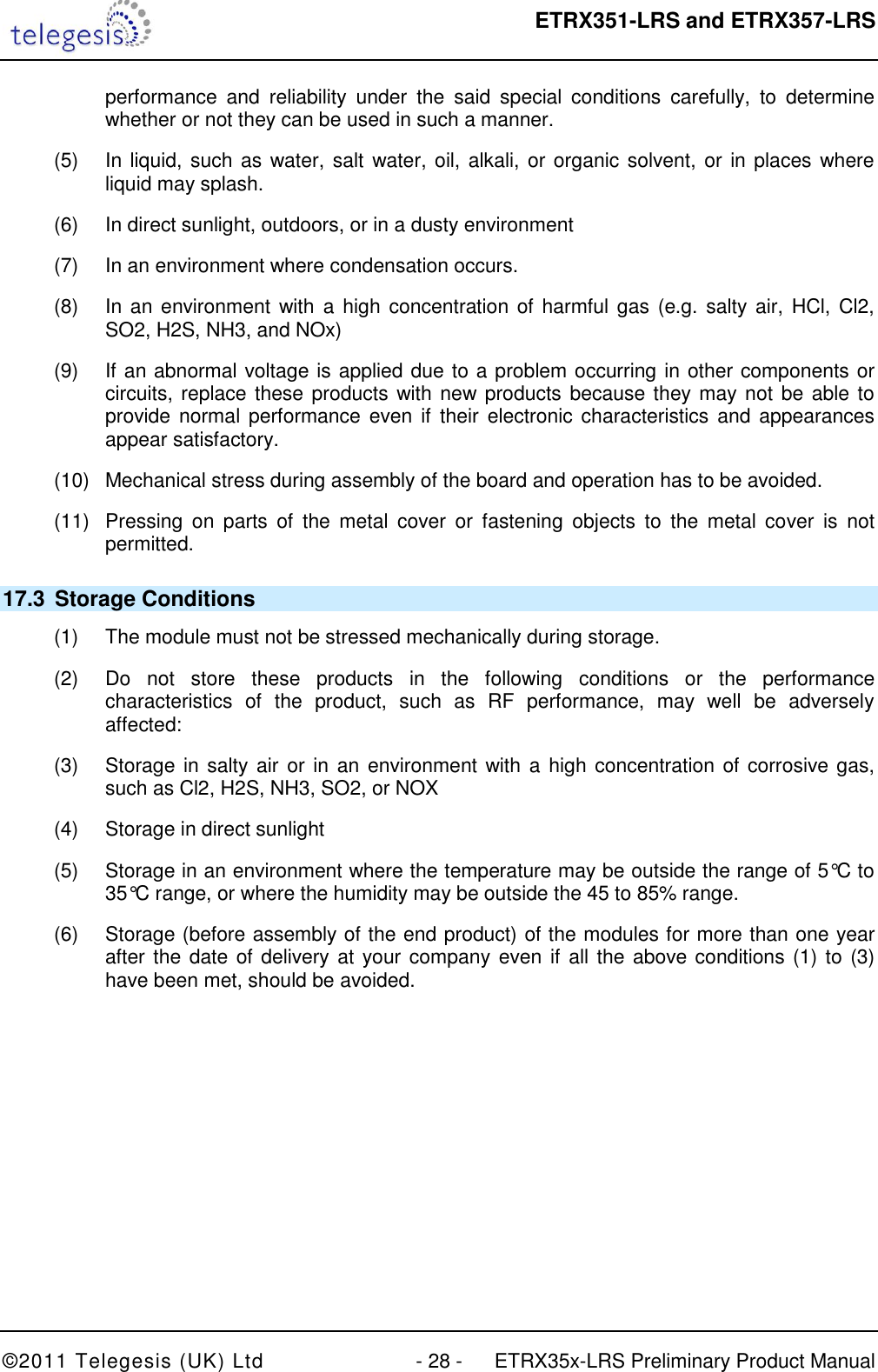
![ETRX351-LRS and ETRX357-LRS ©2011 Telegesis (UK) Ltd - 10 - ETRX35x-LRS Preliminary Product Manual 3 Module Pinout Figure 1: ETRX3 series Module Pinout (top view) The table below gives details about the pin assignment for direct SMD soldering of the ETRX3 series modules to the application board. For more information on the alternate functions please refer to [2]. Also refer to the Telegesis AT Command-set documentation to understand how the pre-programmed firmware makes use of the individual I/Os. All GND pads are connected within the module, but for best RF performance all of them should be grounded externally. ETRX35x pad Designation Normal function Alternate function EM35x pin Ember designation 1 GND GND GND 2 N/C{1} I/O 11 PC5 of the EM35x is used to control the FEM 3 PC6 I/O 13 OSC32B, nTX_ACTIVE 4 PC7 I/O 14 OSC32A, OSC32_EXT 5 PA7 {4} I/O 18 TIM1C4 6 PB3 {2} I/O CTS 19 SC1nCTS, SC1SCLK, TIM2C3 7 nReset nReset 12 8 PB4 {2} I/O RTS 20 TIM2C4, SC1nRTS, SC1nSSEL 9 PA0 I/O 21 TIM2C1, SC2MOSI 10 PA1 I/O 22 TIM2C3, SC2SDA, SC2MISO 11 PA2 I/O 24 TIM2C4, SC2SCL, SC2SCLK 12 PA3 I/O 25 SC2nSSEL, TRACECLK, TIM2C2 13 GND GND GND 14 PA4 I/O 26 ADC4, PTI_EN, TRACEDATA 15 PA5 {3} I/O 27 ADC5, PTI_DATA, nBOOTMODE, TRACEDATA3 16 PA6 {4} I/O 29 TIM1C3 17 PB1 TXD 30 SC1MISO, SC1MOSI, SC1SDA, SC1TXD, TIM2C1 18 PB2 RXD 31 SC1MISO, SC1MOSI, SC1SCL, SC1RXD, TIM2C2 19 GND GND GND 20 GND GND GND 21 JTCK JTCK 32 SWCLK](https://usermanual.wiki/Silicon-Laboratories-Finland/EM35XB.Manual/User-Guide-1411762-Page-10.png)
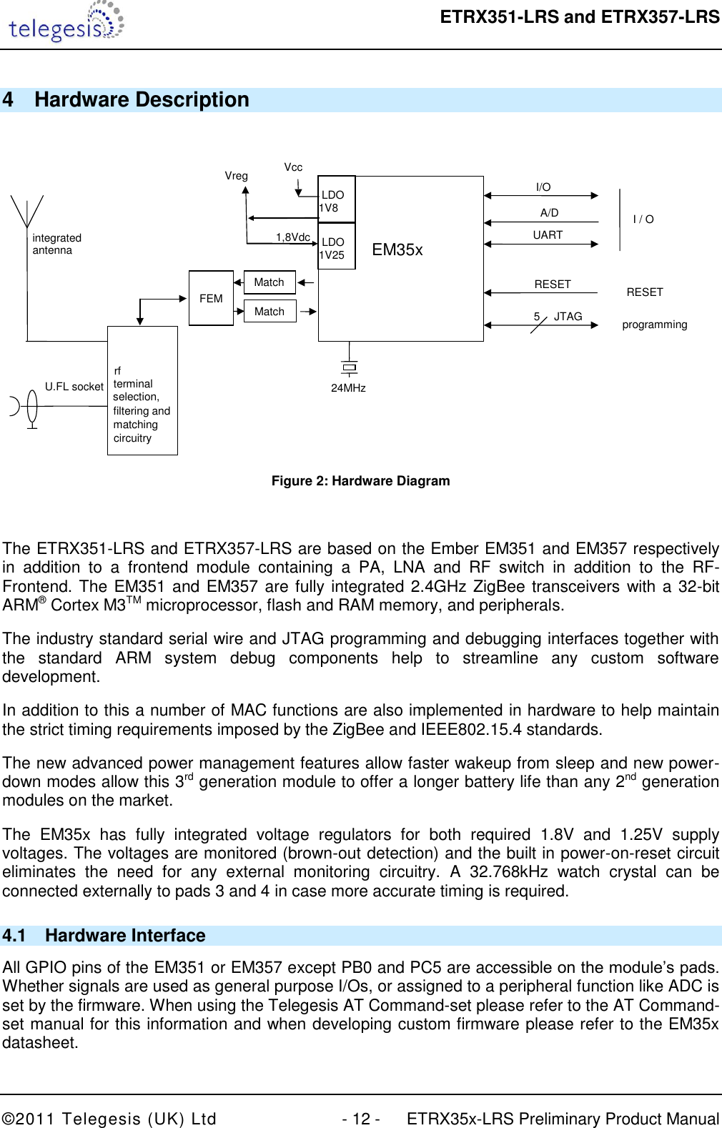
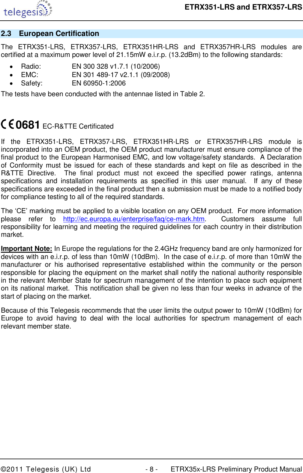
![ETRX351-LRS and ETRX357-LRS ©2011 Telegesis (UK) Ltd - 13 - ETRX35x-LRS Preliminary Product Manual 5 Firmware Description The modules will be pre-loaded with a standalone bootloader by Ember, which supports over-the-air bootloading as well as serial bootloading of new firmware. In order to enter the standalone bootloader using a hardware trigger pull PA5 to ground and power-cycle or reset the module. To avoid entering the standalone bootloader unintentionally make sure not to pull this pin down during boot-up unless the resistance to ground is >10kΩ. A pull-up is not required). In addition to the standalone bootloader the modules also contain the current release of the Telegesis AT-style command interface as described in the Telegesis AT command dictionary and the Telegesis user guide. Check www.telegesis.com for updates. Each module comes with a unique 64-bit 802.15.4 identifier which is stored in non-volatile memory. The commands and responses pass through the serial port of the ETRX35x-LRS as ASCII text, so a simple terminal application will usually suffice. Telegesis Terminal is provided as a development tool, but it is not an essential feature. The pre-loaded AT-style command interface firmware is based on the latest EmberZNet meshing stack which implements routers/coordinators as well as (sleepy) end devices. [End devices have no routing responsibility and therefore are allowed to go to sleep, whilst still being able to send and receive messages via a parent router. In addition to a classical (sleepy) end device the module firmware also supports mobile (sleepy) end devices capable of changing their parent quickly whenever they change their position within the network.] A router is typically a mains powered device whilst a sleepy end device (SED) can be battery powered. The module is also able to act as a PAN coordinator and Trust Centre through external host control. The AT style command line supplies all the tools required to set up and manage a ZigBee network by allowing easy access to the low-level functionality of the stack. The Telegesis firmware uses the meshing and self healing EmberZNet PRO stack to overcome many of the limitations of the tree network topology of the ZigBee® 2006 stack by using the ZigBee PRO feature-set. The Telegesis firmware also allows low-level access to physical parameters such as radio channel and power level. Parameters that define the functionality of the ETRX35x-LRS module and also allow standalone functionality are saved in non-volatile memory organised in so-called S-Registers. The SPI and I2C buses are not supported by the current firmware release, but can be used with custom firmware. 5.1 Custom Firmware For high volume customers the firmware can be customised on request. Customers can use the ETRX35x-LRS module as hardware only and develop application specific firmware based on the EmberZNet stack. In order to develop custom firmware the Ember Insight tool-chain is required.](https://usermanual.wiki/Silicon-Laboratories-Finland/EM35XB.Manual/User-Guide-1411762-Page-13.png)
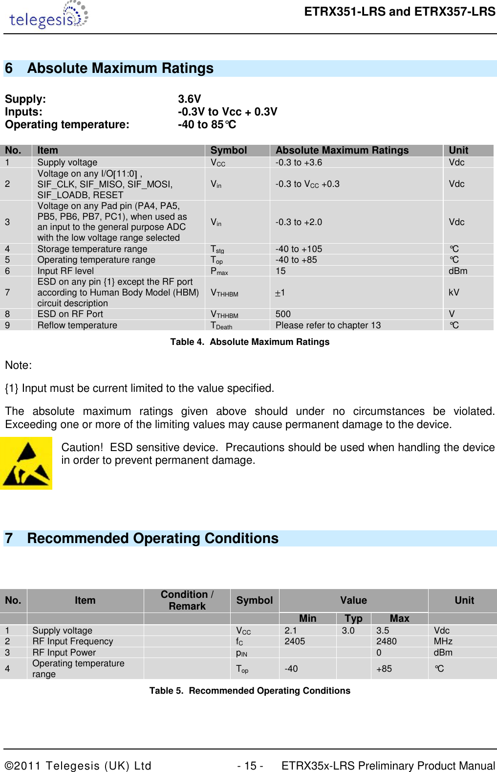
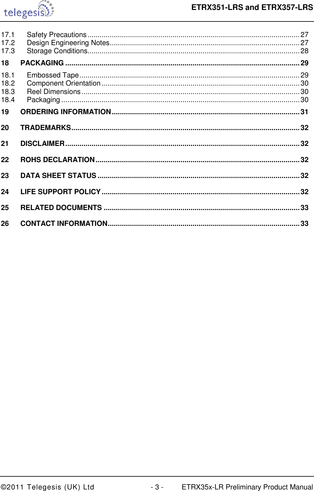
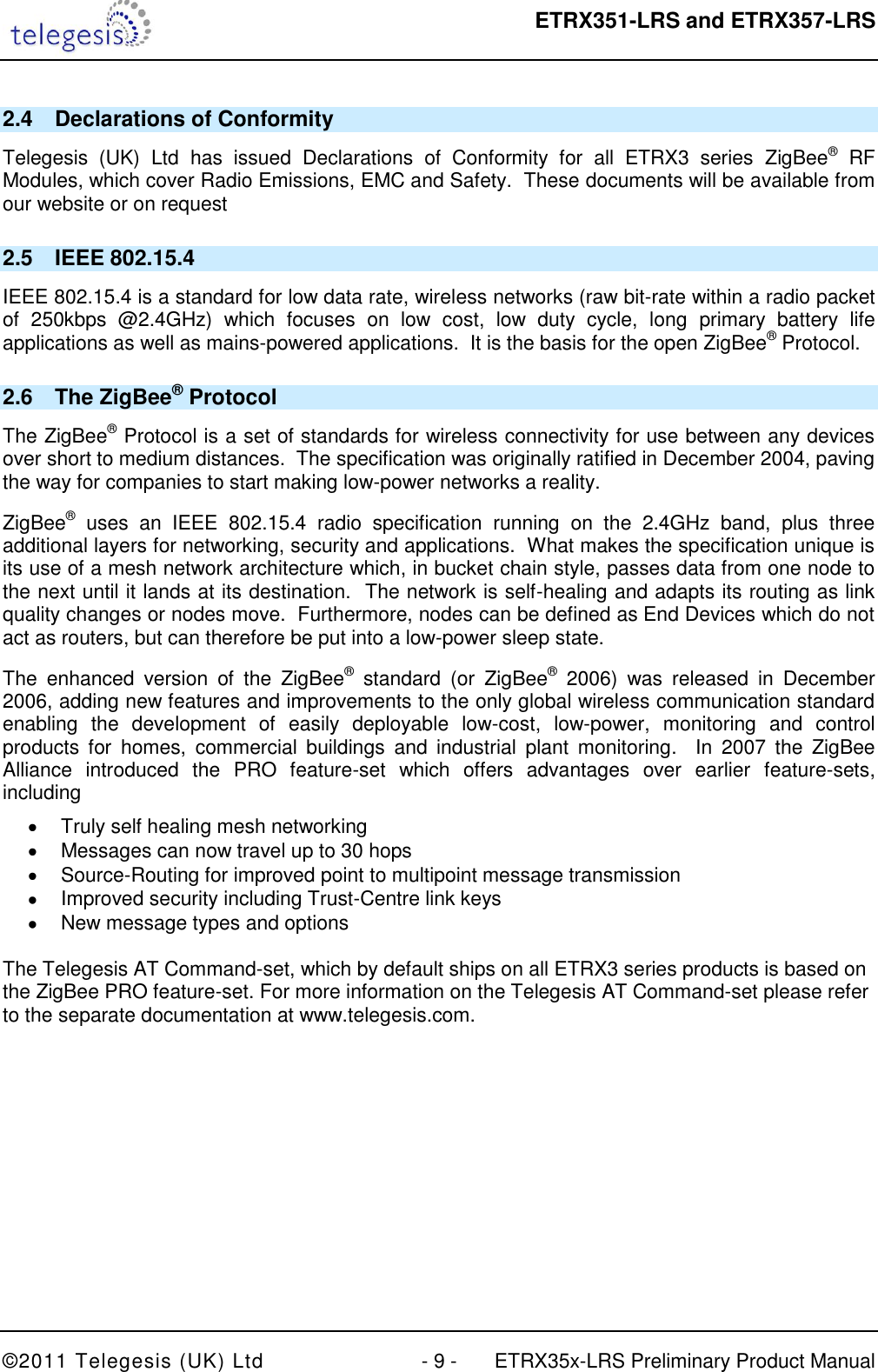
![ETRX351-LRS and ETRX357-LRS ©2011 Telegesis (UK) Ltd - 18 - ETRX35x-LRS Preliminary Product Manual 10 A/D Converter Characteristics The ADC is a first-order sigma-delta converter. For additional information on the ADC please refer to section 10 of the EM35x datasheet. No. Item 1 A/D resolution Up to 12 bits 2 A/D sample time for 5-bit conversion 5.33µs 3 A/D sample time for 12-bit conversion 682µs 4 Reference Voltage 1.2V Table 8. A/D Converter Characteristics 11 AC Electrical Characteristics VCC = 3.0V, TAMB = 25°C, NORMAL MODE measured at 50 terminal load connected to the U.FL socket No. Receiver Value Unit Min Typ Max 1 Frequency range 2400 2500 MHz 2 Sensitivity for 1% Packet Error Rate (PER) -107 -106 -100 dBm 4 Saturation (maximum input level for correct operation) -3 2 dBm 5 High-Side Adjacent Channel Rejection (1% PER and desired signal –82dBm acc. to [1]) tbd dB 6 Low-Side Adjacent Channel Rejection (1% PER and desired signal –82dBm acc. to [1]) tbd dB 7 2nd High-Side Adjacent Channel Rejection (1% PER and desired signal –82dBm acc. to [1]) tbd 8 2nd Low-Side Adjacent Channel Rejection (1% PER and desired signal –82dBm acc. to [1]) tbd 9 Channel Rejection for all other channels (1% PER and desired signal –82dBm acc. to [1]) tbd dB 10 802.11g rejection centred at +12MHz or –13MHz (1% PER and desired signal –82dBm acc. to [1]) tbd dB 11 Co-channel rejection (1% PER and desired signal –82dBm acc. to [1]) tbd dBc 12 Relative frequency error (2x40ppm required by [1]) -120 120 ppm 13 Relative timing error (2x40ppm required by [1]) -120 120 ppm 14 Linear RSSI range 35 dB 15 Output power at highest power setting NORMAL MODE BOOST MODE 20 20 21 21 21.5 21.5 dBm 16 Output power at lowest power setting tbd dBm 17 Error vector magnitude as per IEEE802.15.4 7 15 % 18 Carrier frequency error -40 40 ppm 19 PSD mask relative 3.5MHz distance from carrier tbd dB 20 PSD mask absolute 3.5MHz distance from carrier tbd dBm Table 9. AC Electrical Characteristics](https://usermanual.wiki/Silicon-Laboratories-Finland/EM35XB.Manual/User-Guide-1411762-Page-18.png)
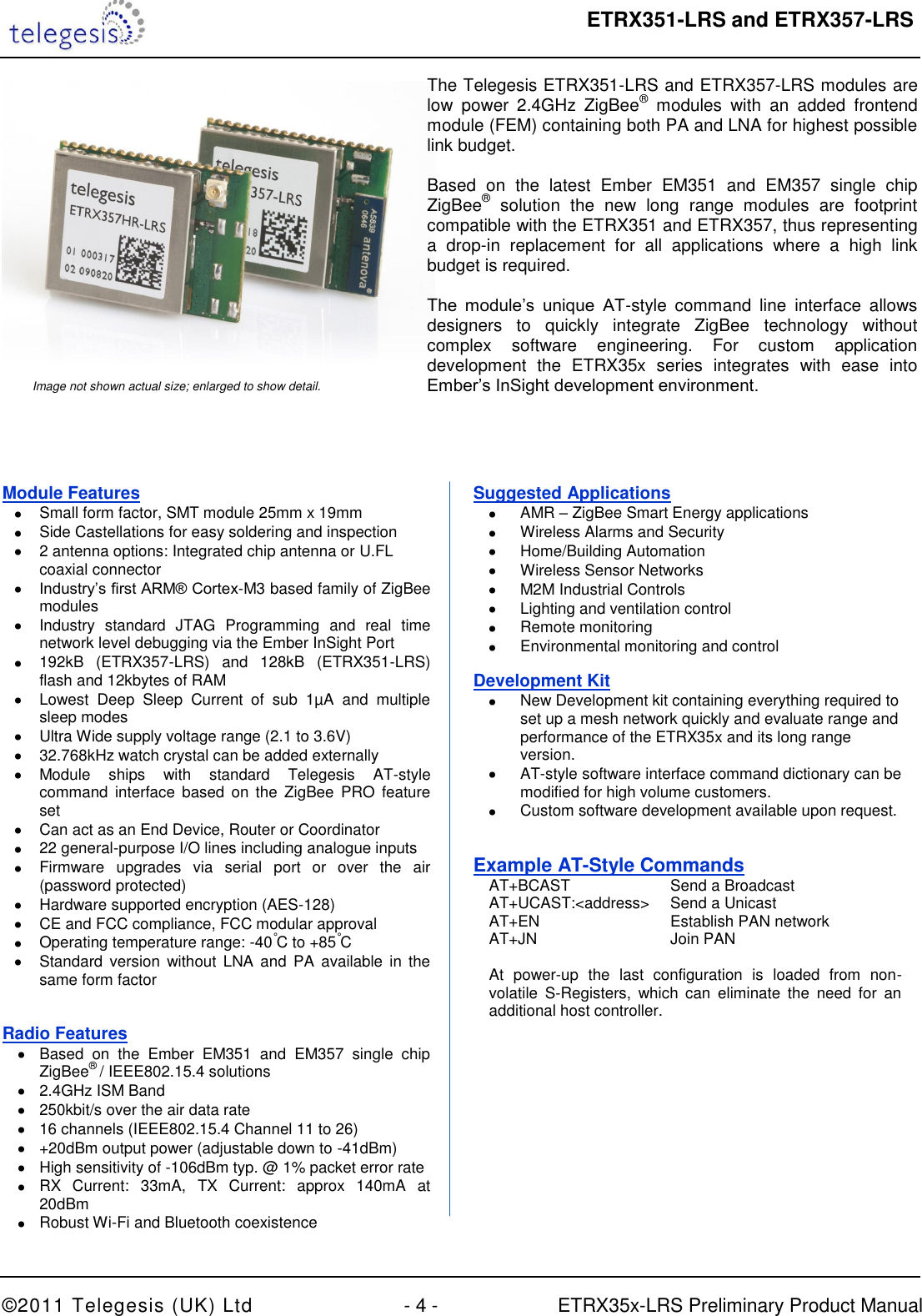
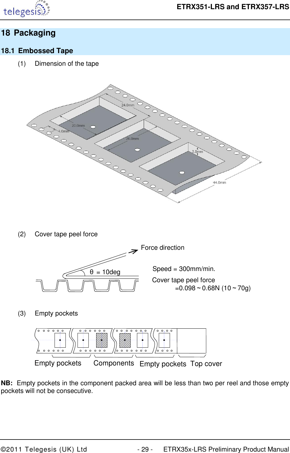
![ETRX351-LRS and ETRX357-LRS ©2011 Telegesis (UK) Ltd - 23 - ETRX35x-LRS Preliminary Product Manual 13 Soldering Temperature Time Profile (for reflow soldering) 13.1 For Leaded Solder Recommended temp. profile for reflow soldering Temp.[°C] Time [s] 235°C max. 220 5°C 200°C 150 10°C 90 30s 10 1s 30 +20/-10s Figure 6. Temperature Profile for Lead Solder 13.2 For Lead-free Solder Our used temp. profile for reflow soldering Temp.[°C] Time [s] 230°C -250°C max. 220°C 150°C – 190°C 90 30s 30 +20/-10s Figure 7. Temperature Profile for Lead-free Solder NB: Maximum Reflow Cycles: 2 Opposite-side reflow is prohibited due to the module’s weight. (I.e. you must not place the module on the bottom / underside of your PCB and re-flow).](https://usermanual.wiki/Silicon-Laboratories-Finland/EM35XB.Manual/User-Guide-1411762-Page-23.png)
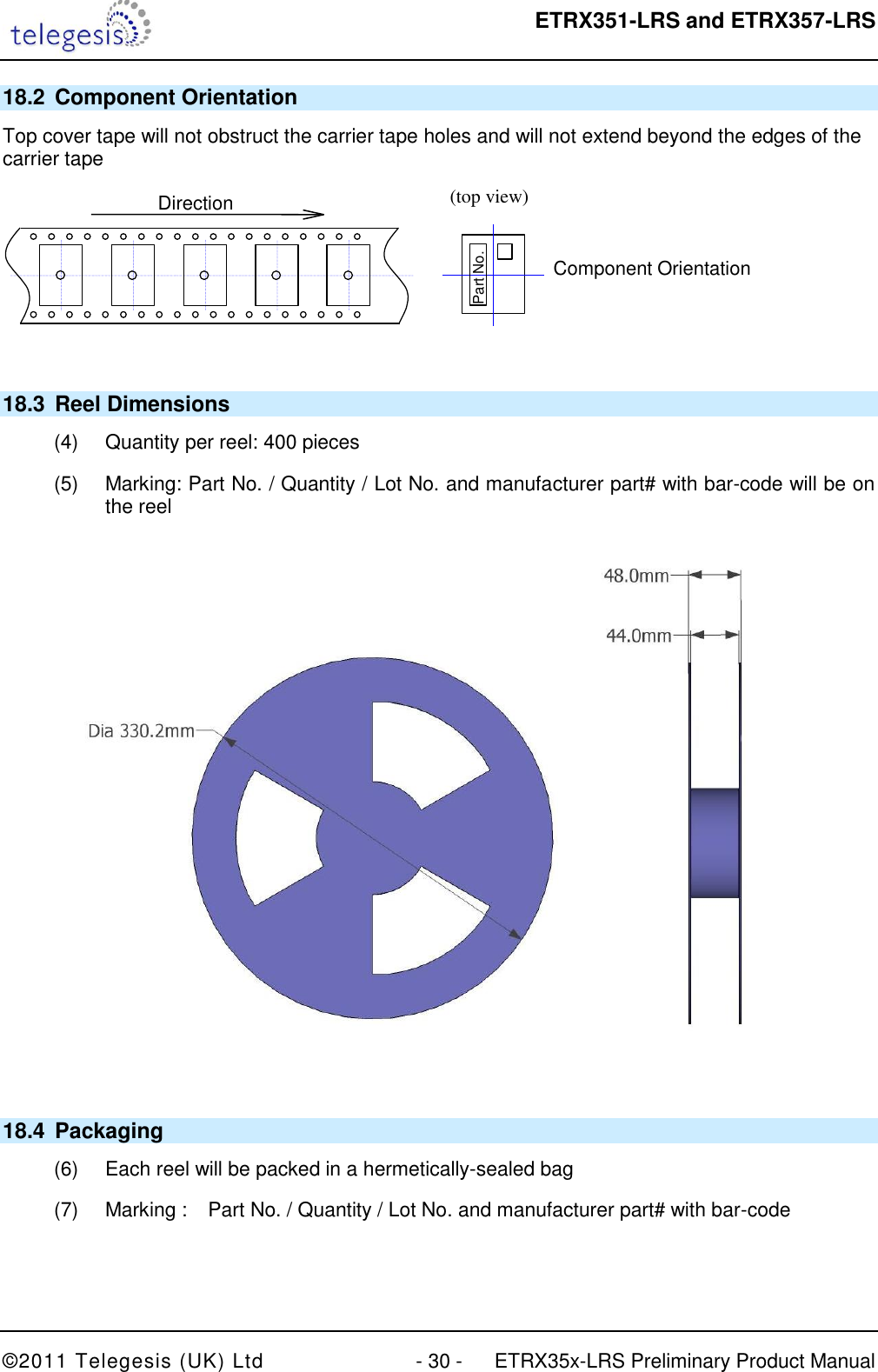
![ETRX351-LRS and ETRX357-LRS ©2011 Telegesis (UK) Ltd - 24 - ETRX35x-LRS Preliminary Product Manual 14 Product Label Drawing Figure 8. Product Label The label dimensions are 16mm x 14 mm. The label will withstand temperatures used during reflow soldering. The characters “HR” are only present on the versions with the Hirose connector, Imprint Description ETRX357HR-LR Module Order code. Possible codes are: - ETRX357-LRS - ETRX351-LRS - ETRX357HR-LRS - ETRX351HR-LRS 000001 Indication for the serial number. 090101 Production Date Code in the format YYMMDD, e.g. 090602 01 Indication for batch number 02 Indication for the hardware revision FCC ID: S4GEM35XB FCC ID code for this product IC: 8735A-EM35XB The IC ID CE The CE Mark 2D-Barcode Information in the 2D-Barcode are the serial number [6 characters], the Part-Order code [12 characters filled with trailing spaces e.g. “ETRX357-LRS “ instead of “ETRX357-LRS”], identifier for the batch number [2 characters], the identifier for the hardware release [2 characters] and the production date code in the format Year-Month-Day [6 characters], separated by a semicolon. Table 17. ETRX3xx-LRS Label Details](https://usermanual.wiki/Silicon-Laboratories-Finland/EM35XB.Manual/User-Guide-1411762-Page-24.png)
![ETRX351-LRS and ETRX357-LRS ©2011 Telegesis (UK) Ltd - 33 - ETRX35x-LRS Preliminary Product Manual 25 Related Documents [1] IEEE Standard 802.15.4 –2003 Wireless Medium Access Control (MAC) and Physical Layer (PHY) Specifications for Low-Rate Wireless Personal Area Networks (LR-WPANs) [2] Datasheet EM35x, Ember. (www.ember.com) [3] Datasheet U.FL-Series 2004.2 Hirose Ultra Small Surface Mount Coaxial Connectors - Low Profile 1.9mm or 2.4mm Mated Height [4] The ZigBee® specification (www.zigbee.org) [5] Specification for Antenova Rufa Antenna (www.antenova.com) 26 Contact Information Website: www.telegesis.com E-mail sales@telegesis.com Telegesis (UK) Limited Abbey Barn Business Centre Abbey Barn Lane High Wycombe Bucks HP10 9QQ UK Tel: +44 (0)1494 510199 Fax: +44 (0)5603 436999](https://usermanual.wiki/Silicon-Laboratories-Finland/EM35XB.Manual/User-Guide-1411762-Page-33.png)