Silicon Labs RS9110N1103 802.11 abgn MODULE User Manual Appendix 9
Redpine Signals Inc 802.11 abgn MODULE Appendix 9
Contents
- 1. User Manual
- 2. Certification Leaflet
User Manual

Redpine Signals, Inc. Proprietary and Confidential
RS9110-N-11-
03 Evaluation Board
User Guide
Version 1.5
Ver
sion 1.5
August
2011
Redpine Signals, Inc
.
2107 N. First Street, #680
San Jose, CA 95131.
Tel: (408) 748-
3385
Fax: (408) 705-
2019
Email: info@redpinesignals.com
Website: www.redpinesignals.com

Redpine Signals, Inc. Proprietary and Confidential
Page 2
RS9110-N-11-
03 Evaluation Board
R
S91
1
0
-N-1
1
-0
3
Eval
u
ati
on
B
o
ard
User Guide
Us
e
r Gu
i
d
e
Version 1.5
Ver
s
i
o
n 1.5
Disclaimer
The information in this document pertains to information relate
d to Redpine
Signals Inc. products. This information is provided as a service to our
customers, and may be used for information purposes only.
Redpine assumes no liabilities or responsibilities for errors or omissions in this
document. This document m
ay be changed at any time at Redpine’s sole
discretion without any prior notice to anyone. Redpine is not committed to
u
pdating these documents in the future.
Copyright © 2011 Redpine Signals, Inc. All rights reserved.

Redpine Signals, Inc. Proprietary and Confidential
Page 3
RS9110-N-11-
03 Evaluation Board
R
S91
1
0
-N-1
1
-0
3
Eval
u
ati
on
B
o
ard
User Guide
Us
e
r Gu
i
d
e
Version 1.5
Ver
s
i
o
n 1.5
Table
of
Contents
1: Introduction.......................................................................5
: Wi-Fi Data Transfer Tests...................................................6
.
1: Test Setup.............................................................................6
.2: Evaluation Software
–
Windows
XP.............................
..........7
.3: Evaluation Process on Windows X
P..............................
.........8
.4: Evalua
tion Software
–
Linux.........
...............................
..........8
.5: Evaluation Process on Linux.........
...............................
..........9
.6: Evaluation Software
–
Windows C
E..............................
.........9
.7: Evaluation Process
on Windows CE......................................10
3: Connector Details.............................................................11
3.1: SPI/SDIO connector............................................................11
3.2: GPIO Interface Header Details.............................................11
3.3: SD Memory Interface...........................................................1
2
4: Compliance Statements....................................................12

Redpine Signals, Inc. Proprietary and Confidential
Page 4
RS9110-N-11-
03 Evaluation Board
R
S91
1
0
-N-1
1
-0
3
Eval
u
ati
on
B
o
ard
User Guide
Us
e
r Gu
i
d
e
Version 1.5
Ver
s
i
o
n 1.5
Table
of
Figures
Figure 1: RS9110-N-11-03 Evaluation Board and Connectors.........................5
Figure 2: RF Cable Connected to the RS9110-N-11-03 Evaluation Board........6
Figure 3: Test Setup for Throughput Measurement.........................................7
Redpine Signals, Inc. Proprietary and Confidential
Page 5
RS9110-N-11-
03 Evaluation Board
R
S91
1
0
-N-1
1
-0
3
Eval
u
ati
on
B
o
ard
User Guide
Us
e
r Gu
i
d
e
Version 1.5
Ver
s
i
o
n 1.5
1: Introduction
The RS9110-N-11-
03 evaluation board provides a complete IEEE 802.11abgn
W
ireless LAN evaluation platform. This basically has the RS9110-N-11-
03
IEEE 8
02.11abgn WLAN module mounted on it along with few other supporting
components such as 40 MHz reference oscillator and other passives. The
RS9110-N-11-03 is a high-performance, low-
power WLAN module.
The board connects to a host processor through SDIO or SPI interfaces. It
also provides the connectivity for the WLAN module to the Vector Signal
Generator (VSG) and Vector Signal Analyzer (VSA) through a microwave
coaxial conn
ector switch.
The RS9110-N-11-
03 evaluation board facilitates you in carrying out following
tests.
E
valuation of the Transmit and Receive performance of the radio
Evaluation of the end–to-
end throughput performance
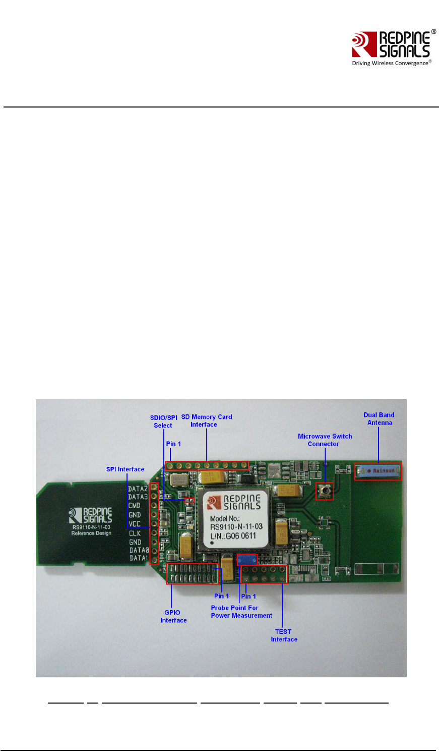
The following picture illustrates various connectors on the RS9110-N-11-
03
evaluation board
Figure 1: RS9110-N-11-03 Evaluation Board and Connectors
Redpine Signals, Inc. Proprietary and Confidential
Page 6
RS9110-N-11-
03 Evaluation Board
R
S91
1
0
-N-1
1
-0
3
Eval
u
ati
on
B
o
ard
User Guide
Us
e
r Gu
i
d
e
Version 1.5
Ver
s
i
o
n 1.5
A probe point
(Jumper PB9) is provided in order to measure the total power
consumed by the RS9110-N-11-
03 module during transmit, receive, and
standby modes.
On board resistors are provided for the Mode Select, which helps the user to
switch from the SDIO host inte
rface to SPI host interface. A JTAG Connector
is also provided to debug process flow control of the evaluation board. A
SMD-
based Microwave switch connector is provided to detach the onboard
antenna, and attach external RF input/output of any signal generator/signal
analyzer through a Microwave Cable Adapter (Murata Part Number –
M
XHS83QH3000).
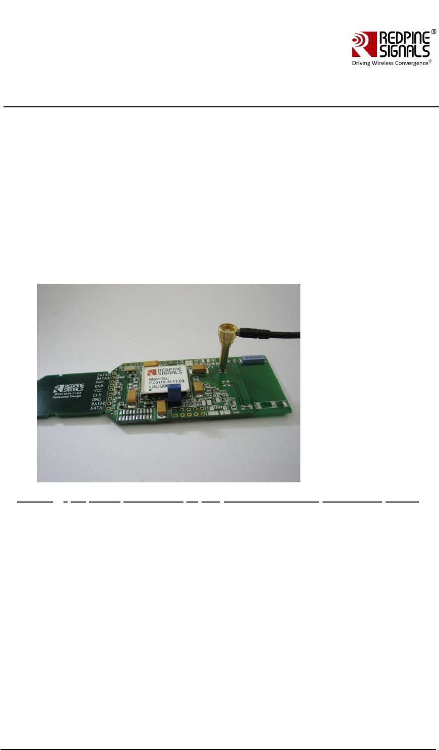
The following diagram illustrates how the user can connect an adapter with
Microwave coaxial
cable to the switch connector.
Figure 2: RF Cable Connected to the RS9110-N-11-03 Evaluation Board
: Wi
-
Fi Data Transfer Tests
The evaluation kit allows you to carry out WLAN data transfer tests, where in
RS9110-N-11-
03 EVB can be connected to any 802.11abgn Access Points and
u
ser can run any network applications to verify the WLAN connection. You can
also evaluate the application level throughputs using this EVB.
I
n order to perform these tests, a Windows XP, or Linux, or Window CE based
W
L
AN driver is provided along with the evaluation kit.
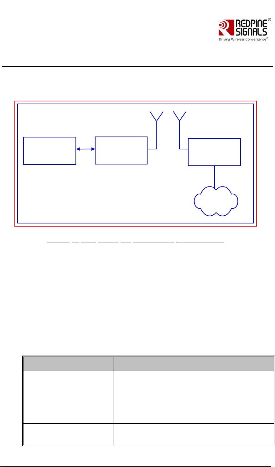
.1: Test Setup
If you want to evaluate the system, you need to have the following test
setup. The EVB is inserted into
the Laptop that has SDIO slot, and it is
w
irelessly connected to an 802.11n Access Point. Data transfer tests can be
performed using any other systems in the LAN, which is connected to AP. The
test setup is shown in the figure below. The sub-
net mask of the wireless
interface on the Laptop and AP should be same as that of the LAN, for which
AP is connected via Ethernet.
Redpine Signals, Inc. Proprietary and Confidential
Page 7
RS9110-N-11-
03 Evaluation Board
R
S91
1
0
-N-1
1
-0
3
Eval
u
ati
on
B
o
ard
User Guide
Us
e
r Gu
i
d
e
Version 1.5
Ver
s
i
o
n 1.5
Please note that, in order to evaluate the Lite-
Fi™ on a Windows CE or a
W
indows Mobile platform, you need to replace the Laptop in the following
setup, with any of the Windows CE or Windows Mobile based SDIO platform.
Laptop
with SDIO slot
8
0
2
.
1
1
n
Access Point
RS9110-N-11-03
EVB
SDIO
Ethernet
LAN
Figure 3: Test Setup for Throughput Measurement
The followin
g is the list of the test setup requirements:
L
aptop with SDIO slot and Windows XP or Linux operating system, or a
W
indows CE or Windows Mobile based SDIO platform.
RS9110-N-11-
03 EVB
8
02.11n Access Point
.2: Evaluation Software –
Windows XP
The following table provides the description of the software package and
installation guides to be used for carrying out the WLAN data transfer tests
u
sing an Access Point, on a Windows XP platform.
Deliverable
Description
L
iteFi_X_Y_Z.exe
This is an installation setup file based on
Windows XP, which will install the Wi-
Fi driver
files into “C:\Program Files\Lite-
Fi”. <X_Y_Z>
indicates the driver version. For example,
LiteFi_2_1_3.exe, means 2.
1.3 version of the
W
indows XP driver.
LiteFi_Driver_Installation_
Guide_WindowsXP.pdf
This is a user guide which provides instructions
on following topics:
Redpine Signals, Inc. Proprietary and Confidential
Page 8
RS9110-N-11-
03 Evaluation Board
R
S91
1
0
-N-1
1
-0
3
Eval
u
ati
on
B
o
ard
User Guide
Us
e
r Gu
i
d
e
Version 1.5
Ver
s
i
o
n 1.5
Installation of the setup file
Host requirements to install the Wi-
Fi driver
Installation of the Wi-
Fi driver
RS9110_N_11_03_WLAN
_Test_Procedure_Window
sXP_V1_0.pdf
This is a user guide on the usage of the driver
and wireless configuration utility to do data
transfer tests under following categories:
11g connection with WPA/WPA2
11n connection with WPA2
11n connection with Aggregation
.3: Evaluation Process on Windows XP
You can start the evaluation process as follows:
Step 1: -
Follow the instructions mentioned in the
LiteFi_Driver_Installation_Guide_WindowsXP.pdf.
Step 2: -
Follow the instructions mentioned in the
RS9110_N_11_03_WLAN_Test_Procedure_WindowsXP.pdf
.
.4: Evaluation Software –
Linux
The following table provides the description of the software package and
installation guides to be used for carrying out the WLAN data transfer tests
u
sing an Access Point, on a Linux platform.
Deliverable
Description
L
iteFi_WLAN_X_Y_Z.tgz
This is an installation setup file b
ased on Linux
platform, which will install the Wi-
Fi driver files
into appropriate user directory. <X_Y_Z>
indicates the driver version. For example,
L
iteFi_WLAN_2_1_3.tgz, means 2.1.3 version
of the Linux driver.
LiteFi_Driver_Installation_G
uide_Linux.pdf
This is a user guide which provides
instructions on following topics:
Installation of the setup file
Host requirements to install the Wi-
Fi
driver
Installation and un-installation of the Wi-
Fi
driver
RS9110_N_11_03_WLAN_T
est_Procedure_Linux.pdf
This is a user guide on the usage of the driver
and wireless configuration utility to do data
transfer tests under following categories in
Redpine Signals, Inc. Proprietary and Confidential
Page 9
RS9110-N-11-
03 Evaluation Board
R
S91
1
0
-N-1
1
-0
3
Eval
u
ati
on
B
o
ard
User Guide
Us
e
r Gu
i
d
e
Version 1.5
Ver
s
i
o
n 1.5
Deliverable
Description
L
inux platform:
11g connection with WPA/WPA2
11n connection with WPA2
11n connection with Aggregation
.5: Evaluation Process on Linux
You can start the evaluation process as follows:
Step 1: -
Follow the instructions mentioned in the
LiteFi_Driver_Installation_Gu
ide_Linux.pdf.
Step 2: -
Follow the instructions mentioned in the
RS9110_N_11_03_WLAN_Test_Procedure_Linux.pdf
.
.6: Evaluation Software –
Windows CE
The following table provides the description of the software package and
installation guides to be us
ed for carrying out the WLAN data transfer tests
u
sing an Access Point, on a Linux platform.
Deliverable
Description
RWLPSDIO_arm_X_Y_Z.cab 8This is an installation setup file for a Windows
CE or Windows Mobile based ARM platform.
<X_Y_Z> indicates the driver version. For
example, RWLPSDIO_arm_2_1_3.cab, means
2.1.3 version of the Windows CE driver.
LiteFi_Driver_Installation_G
uide_WindowsCE.pdf
This is a user guide which provides
instructions on following topics:
Copying the setup file
Host requirements to install the Wi-
Fi
driver
Installation of the Wi-
Fi driver
RS9110_N_11_03_WLAN_T
est_Procedure_WindowsCE.
pdf
This is a user guide on the usage of the driver
and wireless configuration utility to do data
transfer tests under following categories in
W
indows CE platform such as HP-
iPAQ PDA:
11g connection –
Open System
11g connection with WPA
11n connection with WPA

Redpine Signals, Inc. Proprietary and Confidential
Page 10
RS9110-N-11-
03 Evaluation Board
R
S91
1
0
-N-1
1
-0
3
Eval
u
ati
on
B
o
ard
User Guide
Us
e
r Gu
i
d
e
Version 1.5
Ver
s
i
o
n 1.5
.7: Evaluation Process on Windows CE
You can start the evaluation process as follows:
Step 1: -
Follow the instructions mentioned in the
LiteFi_Driver_Installation_Guide_WindowsCE.pdf
Step 2: -
Follow the instructions mentioned in the
RS9110_N_11_03_WLAN_Test_Procedure_WindowsCE.pdf
Redpine Signals, Inc. Proprietary and Confidential
Page 11
RS9110-N-11-
03 Evaluation Board
R
S91
1
0
-N-1
1
-0
3
Eval
u
ati
on
B
o
ard
User Guide
Us
e
r Gu
i
d
e
Version 1.5
Ver
s
i
o
n 1.5
3: Connector Details
This section covers the connector details of various headers.
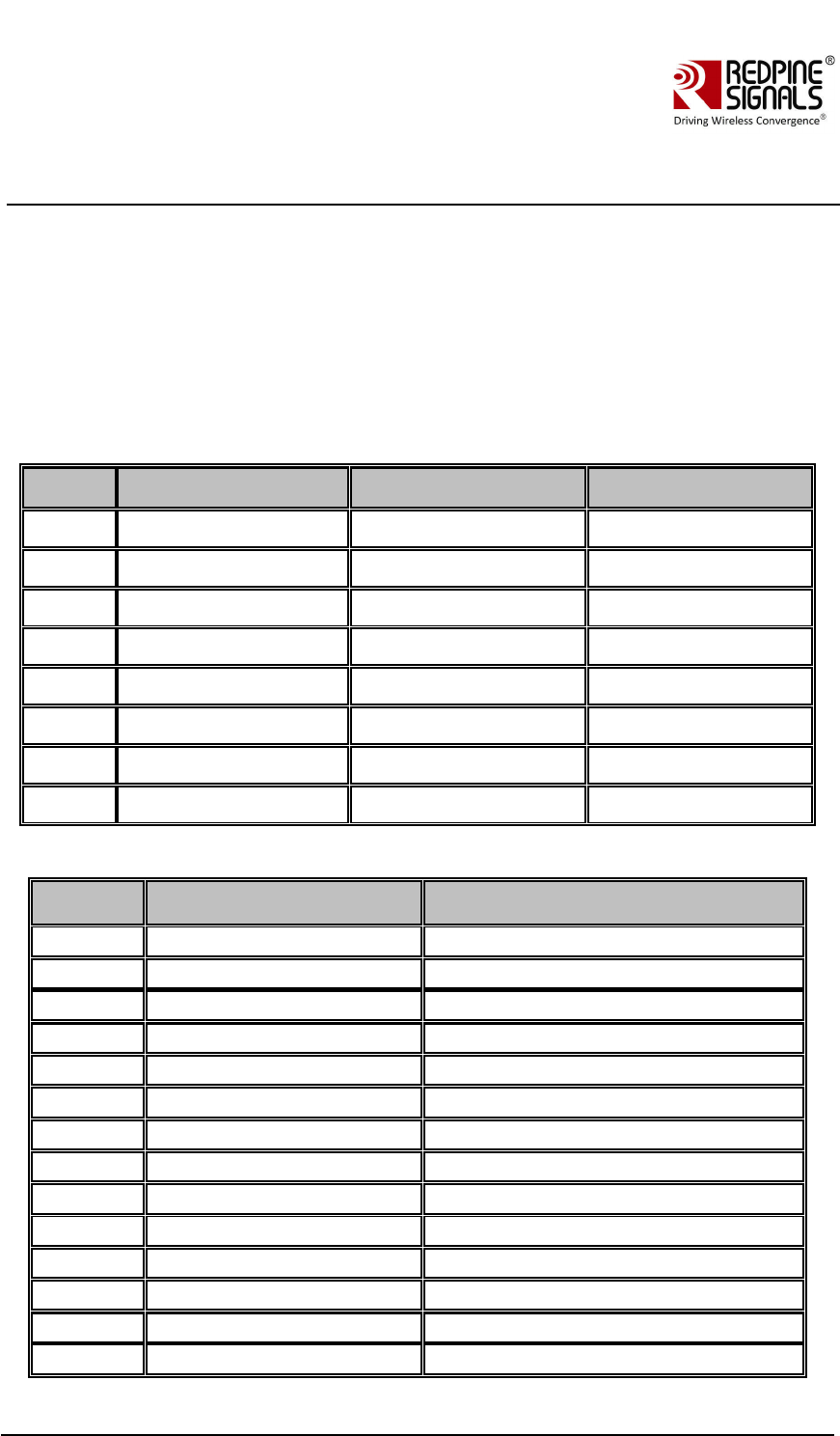
3.1: SPI/SDIO connector
The following table provides the interface details for SPI/SDI
O connector. You
should not install R12, for operating the evaluation board in SDIO Mode.
Conversely, you need to install R12 to put the board into SPI mode.
S. NO
SDIO Signal Names 2SPI Signal Names
C
onnector Pin No.
1)
Sdio_data2
Spi_Intrerrupt
J2.1
2)
Sdio_data3
--
J2.2
3)
Sdio_cmd
Spi_cs
J2.3
4)
Gnd
Gnd
J2.4 & 7
5)
Supply
Supply
J2.5
6)
Sdio_clk
Spi_clk
J2.6
7)
Sdio_data0
Spi_data in
J2.8
)
Sdio_data1
Spi_data out
J2.9
3.2: GPIO Interface Header Details
S. No
Signal Names
C
onnector Pin No.
1)8
Supply
J8.1&2
2)8
GPIO_1
J8.3
3)8
GPIO_0
J8.4
4)
HOST_WAKEUP_INT
J8.5
5)8
XTAL_IP_EN
J8.6
6)8
I2C_SCL
J8.7
7)8
I2C_SDA
J8.8
)
UART1_OUT
J8.9
9)8
UART1_IN
J8.10
10)
W
L
AN_ACTIVE
J8.11
11)
BT_PRIORITY
J8.12
12)
UART1_RST
J8.13
13)
UART2_OUT
J8.14
14)
UART1_CTS
J8.15
R
S91
1
0
-N-1
1
-0
3
Eval
u
ati
on
B
o
ard
User Guide
Us
e
r Gu
i
d
e
Version 1.5
Ver
s
i
o
n 1.5
Redpine Signals, Inc. Proprietary and Confidential
Page 12
S. No
Signal Names
C
onnector Pin No.
15)
BT_ACTIVE
J8.16
16)
VRF28 (DO NOT USE)
J8.17
17)
Gnd
J8.18,19&20
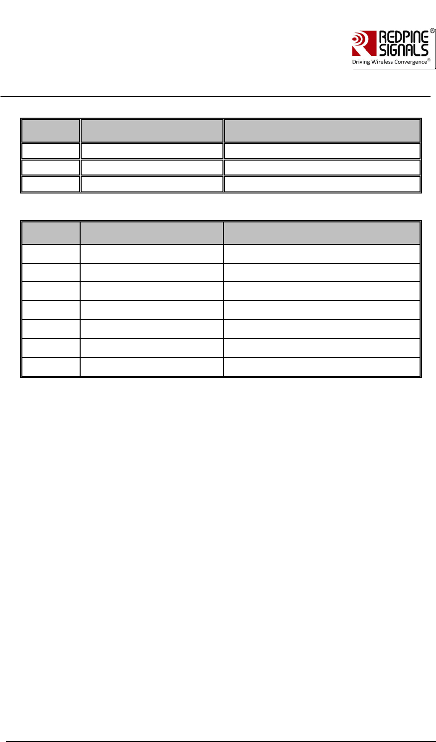
3.3: SD Memory Interface
Redpine Signals, Inc. Proprietary and Confidential
Page 12
S. No
Signal Names
C
onnector Pin No.
15)
BT_ACTIVE
J8.16
16)
VRF28 (DO NOT USE)
J8.17
17)
Gnd
J8.18,19&20
3.3: SD Memory Interface
S. No.
Signal Names
C
onnector Pin No.
1)8
CS
J9.1
2)8
DI
J9.2
3)8
Supply
J9.3
4)
SCLK
J9.4
5)8
GND
J9.5
6)8
DO
J9.6
7)8
CD
J9.6
R
S91
1
0
-N-1
1
-0
3
Eval
u
ati
on
B
o
ard
User Guide
Us
e
r Gu
i
d
e
Version 1.5
Ver
s
i
o
n 1.5
4
: Compliance Statements:
4.1 FCC Compliance Statements
This device complies with Part 15 of the FCC rules. Operation is subject to following
Two conditions: 1. this device may not cause harmful interference and 2. This device
Must accept any interference received including interference that may cause undesired
Operation of this device.
The changes or modifications not expressly approved by the party responsible for
Compliance could void the user’s authority to operate the equipment.
To comply with the FCC RF exposure compliance requirements, this device and its antenna
Must not be co-located or operating to conjunction with any other antenna or transmitter,
Except if installed in compliance with FCC Multi Transmitter procedures.
To inherit the modular approval, the antennas for this transmitter must be installed to provide
A separation distance of 20cm from all persons and must not be co-located or operating in
Conjunction with any other antenna or transmitter.

Note: This equipment has been tested and found to comply with the limits for a Class B digital device,
Pursuant to part 15 of the FCC Rules. These limits are designed to provide reasonable
Protection against harmful interference in a residential installation. This equipment generates
Uses and can radiate radio frequency energy and, if not installed and used in accordance
With the instructions, may cause harmful interference to radio communications. However,
There is no guarantee that interference, Will not occur in a particular installation. If this equipment
Does cause harmful interference to radio or television reception, which can be determined by turning
The equipment off and on, the user is encouraged to try to correct the interference by one or
More of the following measures:
- Reorient or relocate the receiving antenna.
- Increase the separation between the equipment and receiver.
- Connect the equipment into an Outlet on a circuit different from that to which the receiver is connected.
CAUTION: The operation of this radio in the 5.15-5.25 GHz frequency band is restricted to indoor use only.
To OEM Installer:
1. FCC and IC ID on the final system must be labeled with “Contains FCC ID: XF6-RS9110N1103” and
IC ID: 8407A - RS9110N1103
or
“Contains transmitter Module FCC ID: XF6-RS9110N1103 “and
“Contains transmitter Module IC ID: 8407A - RS9110N1103
2. In the user manual, final system integrator must ensure that there is no instruction provided in the user
Manual to install or remove the transmitter module.
3. Transmitter module must be installed used in strict accordance with the
Manufacturer’s instructions as described in the user documentation that comes with the product.
The user manual of the final host system must contain the following statements:
This device complies with Part 15 of the FCC rules. Operation is subject to following
Two conditions: 1. this device may not cause harmful interference and 2. This device
Must accept any interference received including interference that may cause undesired operation of this device.
The changes or modifications not expressly approved by the party responsible for
Compliance could void the user’s authority to operate the equipment.
To comply with the FCC RF exposure compliance requirements, this device and its antenna must not
Be co-located or operating to conjunction with any other antenna or transmitter, except if installed
In compliance with FCC Multi Transmitter procedures.
To inherit the modular approval, the antennas for this transmitter must be installed to provide a
Separation distance of at least 20cm from all persons and must not be co-located or operating in
Conjunction with any other antenna or transmitter.
Note:
The buyer of the module who will incorporate this module into his host must submit the final product to the
Manufacturer of the module and the MANUFACTURER OF THE MODULE WILL VERIFY that the product
Is incorporated in host equipment in a way that is represented by the testing as shown in the test report.
Redpine Signals, Inc. Proprietary and Confidential Page 13
R
S91
1
0
-N-1
1
-0
3
Eval
u
ati
on
B
o
ard
User Guide
Us
e
r Gu
i
d
e
Version 1.5
Ver
s
i
o
n 1.5

4.2 IC Compliance Statements:
This Class B digital apparatus complies with Canadian ICES-003.
This device complies with Industry Canada license-exempt RSS standard(s). Operation is subject to the
Following two conditions :( 1) this device may not cause interference, and
(2) This device must accept any interference, including interference that may cause undesired operation of the device.
Le présent appareil est conforme aux CNR d'Industrie Canada applicables aux appareils radio exempts de licence.
L'exploitation est autorisée aux deux conditions suivantes : (1) l'appareil ne doit pas produire de brouillage, et
(2) l'utilisateur de l'appareil doit accepter tout brouillage radioélectrique subi, même si le brouillage est susceptible
d'en compromettre le fonctionnement.
For local area network devices shall contain instructions related to the restriction Mentioned in the below, namely that:
(i) The device for operation in the band 5150-5250 MHz is only for indoor use to reduce the potential for harmful
Interference to co-channel mobile satellite systems.
This equipment complies with radio frequency exposure limits set forth by Industry Canada for an uncontrolled
Environment. This equipment should be installed and operated with minimum distance 20 cm between the device
And the user or bystanders.
Cet équipement est conforme aux limites d'exposition aux radiofréquences définies par Industrie Canada pour
un environnement non contrôlé. Cet équipement doit être installé et utilisé avec un minimum de 20 cm de distance
entre le dispositif et l'utilisateur ou des tiers.
énoncé de la FCC (états-Unis seulement) Cet équipement a été testé et jugé
conforme aux limites de Classe B pour un appareil numérique, en vertu de l’article
15 de la réglementation de la FCC. Ces limites ont été instaurées our fournir une
rotection raisonnable contre toute interférence nuisible dans une installation résidentielle.
Cet équipement génère, utilise et peut émettre de l’énergie radiofréquence. S’il n’est pas
installé et utilisé conformément aux instructions, il peut provoquer des interférences sur les
communications radio. Cependant, il n’est pas garanti que des interférences ne se produiront pas
dans certaines installations. Si cet équipement cause des interférences à la reception
radio ou télévisée (ce qui peut être vérifi é en éteignant l’appareil puis en le
remettant sous tension), l’utilisateur peut enter de résoudre en suivant une
ou plusieurs des mesures ci-après : Réorienter ou déplacer l’antenne réceptrice.
ugmenter l’espace entre l’appareil et le récepteur. Brancher l’appareil à une prise
de courant différente de celle sur laquelle le récepteur est branché. Pour
obtenir de l’aide, contacter le vendeur ou un technician radio/television expérimenté.
REMARQUE: Toute modifi cation non autorisée expressément par le fabricant responsable de la
onformité peut annuler le droit de l’utilisateur à faire fonctionner le produit.
Redpine Signals, Inc. Proprietary and Confidential Page 14
S91
1
0
-N-1
1
-0
3
Eval
u
ati
on
B
o
ard
User Guide
Us
e
r Gu
i
d
e
R
R
S91
1
0
-N-1
1
-0
3
Eval
u
ati
on
B
o
ard
User Guide
Us
e
r Gu
i
d
e
Version 1.5
Ver
s
i
o
n 1.5