Silicon Labs RS9110N1124 802.11 bgn Connection MODULE User Manual RS9110 N 11 24
Redpine Signals Inc 802.11 bgn Connection MODULE RS9110 N 11 24
Manual

Redpine Signals, Inc. Proprietary and Confidential.
Connect-io-n™
RS9110-N-11-24
E
Ev
va
al
lu
ua
at
ti
io
on
n
B
Bo
oa
ar
rd
d
U
Us
se
er
r
G
Gu
ui
id
de
e
V
Ve
er
rs
si
io
on
n
3
3.
.1
13
3
April 2013
Redpine Signals, Inc
.
2107 N. First Street, #680
San Jose, CA 95131.
Tel: (408) 748-3385
Fax: (408) 705-2019
Email: info@redpinesignals.com
Website: www.redpinesignals.com
Redpine Signals, Inc
.
2107 N. First Street, #680
San Jose, CA 95131.
Tel: (408) 748-3385
Fax: (408) 705-2019
Email: info@redpinesignals.com
Website: www.redpinesignals.com

Redpine Signals, Inc. Page 2
Connect
-
io
-
n™
RS9110-N-11-24
Evaluation Board User Guide
V
V
e
e
r
r
s
s
i
i
o
o
n
n
3
3
.
.
1
1
3
3
Part Number Description
Device Number Description TCP/IP
Enabled
Option for
TCP/IP Bypass
RS9110-N-11-24 Part with UART as
Host Interface
Yes No
RS9110-N-11-24-02 Part with SPI as
Host Interface
Yes Yes
RS9110-N-11-24-04 Part with
UART/SPI as Host
Interface
Yes Yes
RS9110-N-11-24-04 will replace RS9110-N-11-24 and RS9110-N-11-24-02.
RS9110-N-11-24-04 is feature compatible with RS9110-N-11-24 and RS9110-
N-11-24-02.

Redpine Signals, Inc. Page 3
Connect
-
io
-
n™
RS9110-N-11-24
Evaluation Board User Guide
V
V
e
e
r
r
s
s
i
i
o
o
n
n
3
3
.
.
1
1
3
3
Table of Contents
1 Introduction ........................................................................ 6
2 Components on the EVBs ..................................................... 7
3 Using the Evaluation Board in UART mode ......................... 10
3.1 Configure Serial port in computer .........................................10
3.2 Configure Serial Port Monitor in the PC .................................14
3.3 Evaluating the Module in Infrastructure mode .......................18
3.3.1 Configuration and Test Procedure .................................................... 18
3.4 Evaluating the Modules in Ad-hoc mode ................................24
3.5 Upgrading Firmware .............................................................25
3.5.1 Firmware Upgrade Using UART Interface without wireless firmware
upgrade feature ............................................................................ 25
3.5.2 Firmware Upgrade Using UART Interface with wireless firmware upgrade
feature’ ........................................................................................ 30
3.5.3 Firmware Upgrade from 4.7.x to a higher version Wirelessly ............... 32
3.6 Using the Wireless Configuration Feature..............................35
3.6.1.1 Wireless Configuration in AP Mode.............................................. 35
3.6.1.2 Wireless Configuration When the Module is Connected to an AP ..... 40
3.7 General Operation of the Modules .........................................44
4 Using the Evaluation Board in SPI mode ............................ 46
4.1 TCP/IP Stack Usage in RS9110-N-11-24–SPI mode ...............47
4.1.1 Using the Wi-Fi module with TCP/IP stack enabled ............................. 47
4.1.2 Using the Wi-Fi module with TCP/IP stack bypassed ........................... 48
4.2 SPI Operations .....................................................................49
5 FCC and IC Declaration ...................................................... 53

Redpine Signals, Inc. Page 4
Connect
-
io
-
n™
RS9110-N-11-24
Evaluation Board User Guide
V
V
e
e
r
r
s
s
i
i
o
o
n
n
3
3
.
.
1
1
3
3
Table of Figures
Figure 1: Evaluation Set-up - Infrastructure Mode ..................................... 18
Figure 2: Hyperterminal Messages ............................................................. 21
Figure 3: Messages in Laptop (C) ............................................................... 21
Figure 4: General Sequence of Commands ................................................. 23
Figure 5: Evaluation Set-up – Ad-hoc Mode ................................................ 24
Figure 6: Wireless Firmware Upgrade Set-up ............................................. 32
Figure 7: Configuration GUI ....................................................................... 33
Figure 8: Wireless Configuration Set-up ..................................................... 36
Figure 9: Configuration GUI ....................................................................... 37
Figure 10: Wireless Configuration Set-up ................................................... 40
Figure 12: Firmware Upgrade and General Operation in UART modules ..... 45
Figure 13: Connections in SPI mode ........................................................... 46
Figure 14: Architecture with TCP/IP Enabled ............................................. 48
Figure 15: Architecture with TCP/IP Bypassed .......................................... 49

Redpine Signals, Inc. Page 5
Connect
-
io
-
n™
RS9110-N-11-24
Evaluation Board User Guide
V
V
e
e
r
r
s
s
i
i
o
o
n
n
3
3
.
.
1
1
3
3
List of Tables
Table 1: UART Header Pins ........................................................................... 8
Table 2: SPI Header Pins .............................................................................. 9
Table 3: DIP Switch Setting (6 switches) ..................................................... 9

Redpine Signals, Inc. Page 6
Connect
-
io
-
n™
RS9110-N-11-24
Evaluation Board User Guide
V
V
e
e
r
r
s
s
i
i
o
o
n
n
3
3
.
.
1
1
3
3
1 Introduction
This document describes how to use the RS9110-N-11-24 EVB. It
describes the sequence of commands and set-up requirements to quickly
evaluate the major functions of the modules.
Chapters Using the Evaluation Board in UART mode to Evaluating the
Module in Infrastructure mode describe operation using the UART
interface. Using the Evaluation Board in SPI mode describes operation
using the SPI interface. Upgrading Firmware describes the firmware
upgrade procedure. Even if the user does not plan to use the UART
interface, it is recommended to go through the UART section because all
the set-ups to evaluate different functionalities of the module in UART
mode are directly reusable in the SPI mode also.
Redpine Signals, Inc. Page 7
Connect
-
io
-
n™
RS9110-N-11-24
Evaluation Board User Guide
V
V
e
e
r
r
s
s
i
i
o
o
n
n
3
3
.
.
1
1
3
3
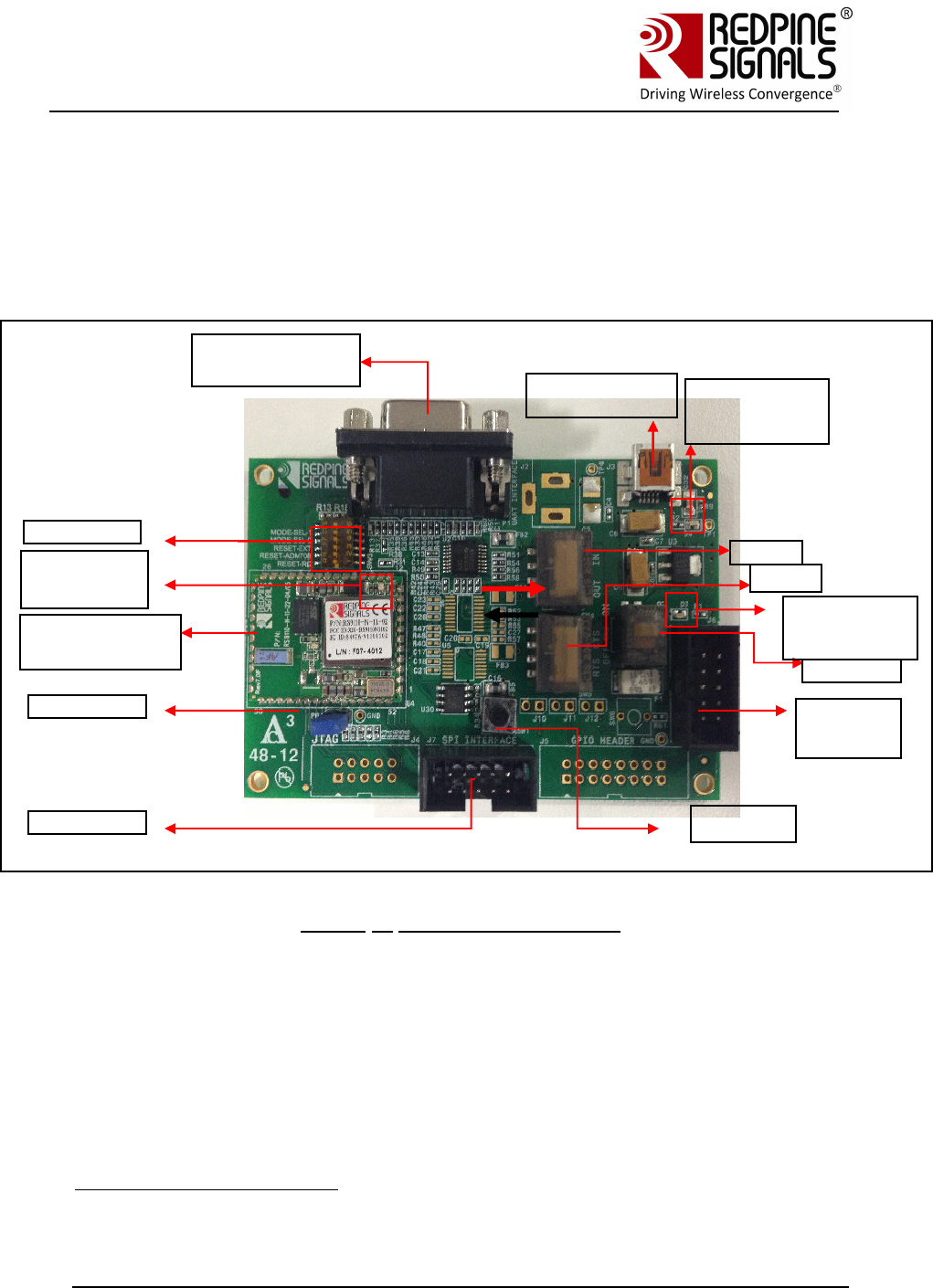
2 Components on the EVBs
The RS9110-N-11-24 EVB has various switches and headers to enable the user to
configure it for different scenarios1. The figure below shows the various
components. The exact EVB may differ slightly from the pictures below due to
different PCB versions or minor changes.
Figure 1: RS9110-N-11-24-EVB
1 All components described in this section may not be present in different versions
of the EVB PCB. General functionality will however not be affected.
DB9 Connector
for UART
RS9110-N-11-24
module
DIP Switches
SW4
Power
switch
SW5
USB Connector
for Power
SPI Header
2 Pin Jumper
UART
Header for
MCU
LED1: Glows when
power supply
cable is inserted
LED2: Glows
when power
switch is in on
position
LED3: Glows
after
successful
boot
-
up
Push
Button
Redpine Signals, Inc. Page 8
Connect
-
io
-
n™
RS9110-N-11-24
Evaluation Board User Guide
V
V
e
e
r
r
s
s
i
i
o
o
n
n
3
3
.
.
1
1
3
3
USB Connector for Power
The power for the board can be supplied through this connector.
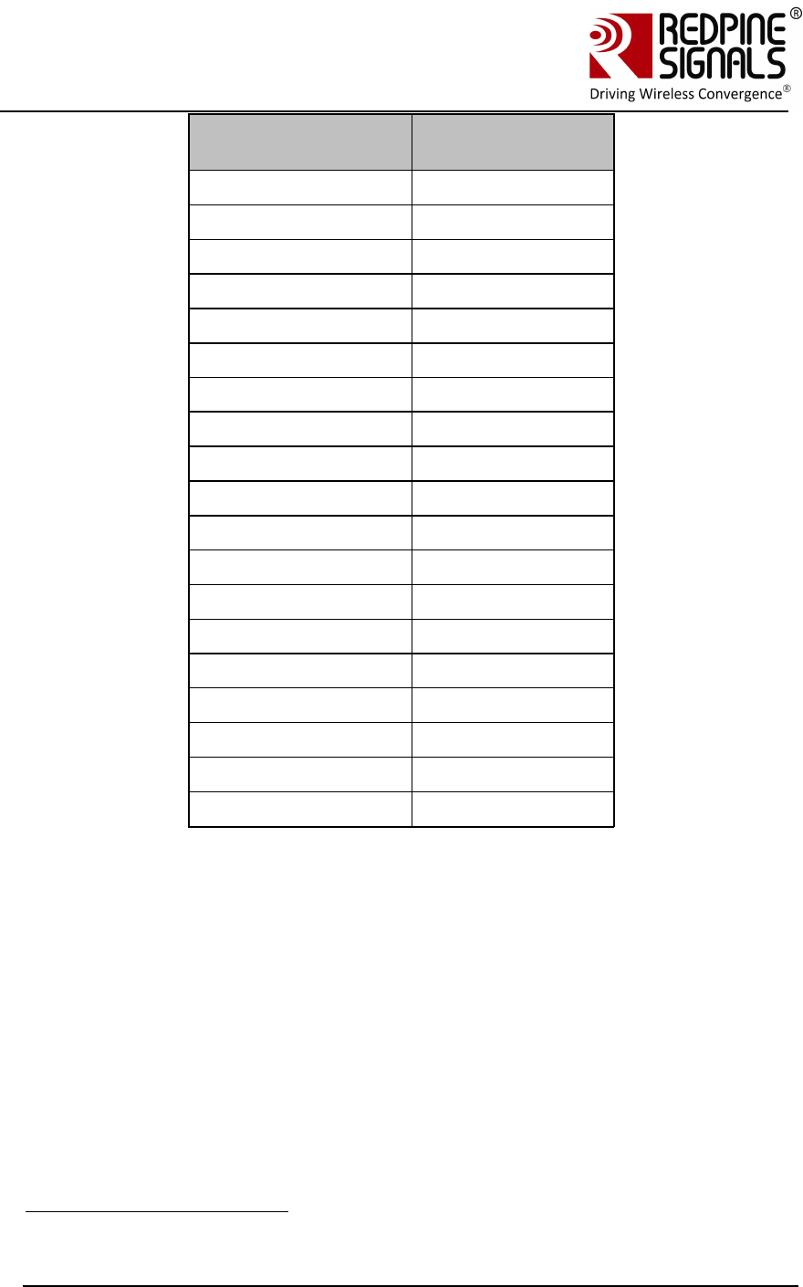
UART Header for MCU
If the EVB needs to be connected to the serial interface of an MCU platform, this
header can be used. The voltage level of the UART TX and RX pins of this header
is 3.3V. The Ground pin should be connected to a corresponding ground signal of
the MCU board.
Pin
number
Pin
name Direction
Description
1
NC
-
This pin must be left
unconnected
2
NC
-
This pin must be left
unconnected
3
NC
-
This pin must be left
unconnected
4
UART
-
RX
Input
UART RX pin of the
module
5
UART
-
TX
Output
UART TX pin of the
module
6
NC
-
No connect
7
NC
-
No connect
8
GND
-
Ground
9
GND
-
Ground
10
GND
-
Ground
Table 1: UART Header Pins
SPI Header
The SPI header is used to connect the SPI interface of the module to a Host
MCU. The pin configuration of this header is as follows:
Pin
number
Pin name Direction
Description
1
NC
-
No connect
2
SPI_CS
Input
SPI sl
ave select
3
GND
-
Ground
4
VCC
-
3.3V power supply. If
the USB port for power
supply is not used, this
pin can be used to drive
power to the EVB from
the Host MCU platform.
The maximum current
Redpine Signals, Inc. Page 9
Connect
-
io
-
n™
RS9110-N-11-24
Evaluation Board User Guide
V
V
e
e
r
r
s
s
i
i
o
o
n
n
3
3
.
.
1
1
3
3
sourcing capacity of the
Host should be 500mA.
If not used, this pin
should be left open
5
SPI_CLK
Input
SPI clock
6
GND
-
Ground
7
SPI_MOSI
Input
SPI data input
8
SPI_MISO
Output
SPI data output
9
INTR
Output
Interrupt output (Active
high)
10
NC
-
No connect
Table 2: SPI Header Pins
DIP Switches
The DIP switches are used to select the module to work in UART or SPI mode.
Switch
#
Status
Comment
1,2,3
ON, OFF, OFF
Power on reset selected
1,2,3
OFF, ON, OFF
Push button reset
selected
1,2,3
OFF, OFF, ON
Reset from Host
selected
4,5
ON, ON
SPI mode selected
4,5
OFF, OFF
UART mode selected
6
OFF
Keep in OFF mode
Table 3: DIP Switch Setting (6 switches)
Note: If Reset from Host selected using DIP switch settings then 14th pin of GPIO
header should be connected to the host. If EVB has 4 switches DIP switch then
resistor R19 should be populated with 0 ohms.
SW4 and SW5
These switches are used to select the UART DB9 connector or the “UART Header
for MCU” for communicating using the UART interface. The direction shown with
the thick red arrow is to select the DB9 connector. The direction shown with the
thick black arrow is to select the UART Header.
2 Pin Jumper
Used for Power measurements.
Redpine Signals, Inc. Page 10
Connect
-
io
-
n™
RS9110-N-11-24
Evaluation Board User Guide
V
V
e
e
r
r
s
s
i
i
o
o
n
n
3
3
.
.
1
1
3
3
3 Using the Evaluation Board in UART mode
The following sections describe how to use the Evaluation Board in UART
mode.
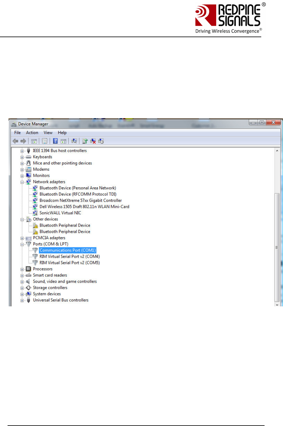
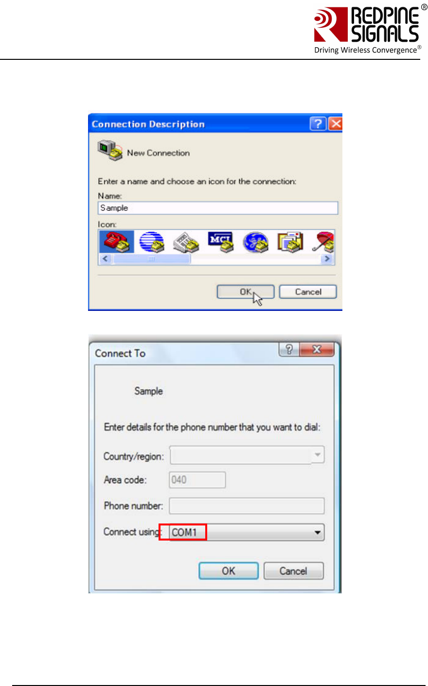
3.1 Configure Serial port in computer
To know the COM port name, check the computer’s Device Manager settings.
The COM port name is displayed in the window. Hyperterminal or Teraterm should
be opened and configured accordingly with this COM port name.
The steps for configuring HyperTerminal are shown below.
Redpine Signals, Inc. Page 11
Connect
-
io
-
n™
RS9110-N-11-24
Evaluation Board User Guide
V
V
e
e
r
r
s
s
i
i
o
o
n
n
3
3
.
.
1
1
3
3
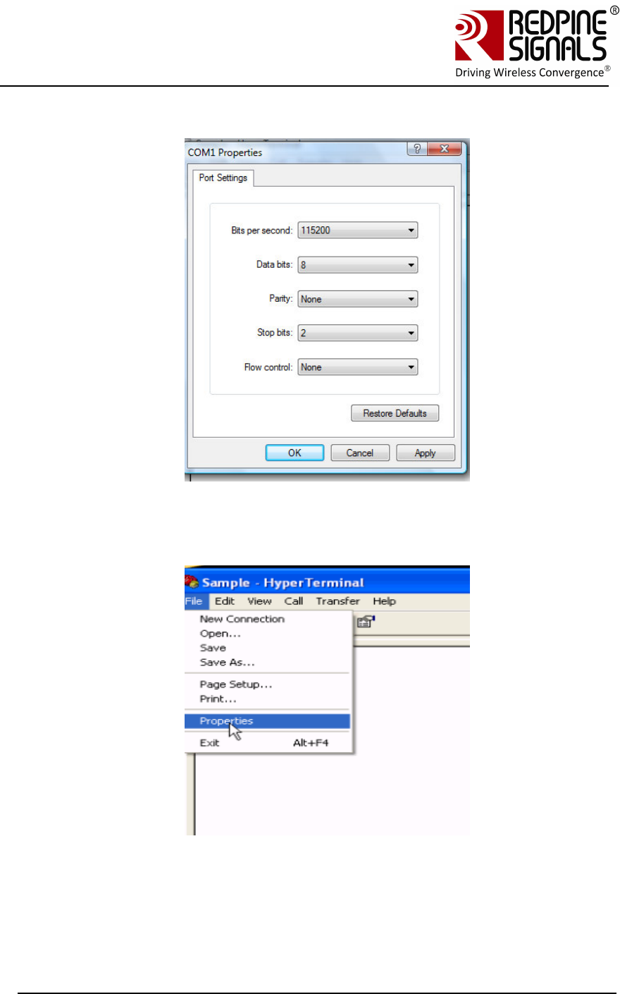
Open HyperTerminal
Baud Rate: 115200 bps, Data bits: 8, Parity: None, Stop bits: 2, Flow Control:
None
Currently other baud rates are not supported.
Redpine Signals, Inc. Page 12
Connect
-
io
-
n™
RS9110-N-11-24
Evaluation Board User Guide
V
V
e
e
r
r
s
s
i
i
o
o
n
n
3
3
.
.
1
1
3
3
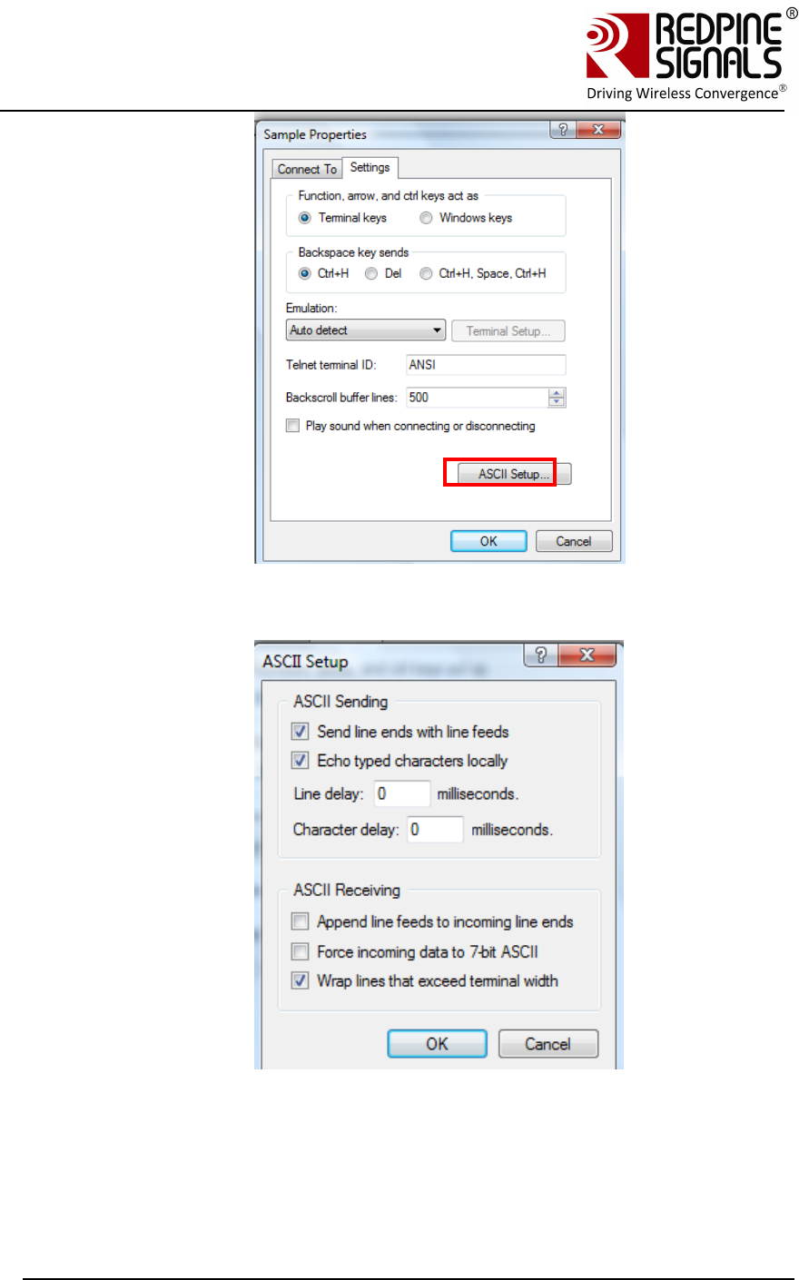
Click on ASCII Setup
Redpine Signals, Inc. Page 13
Connect
-
io
-
n™
RS9110-N-11-24
Evaluation Board User Guide
V
V
e
e
r
r
s
s
i
i
o
o
n
n
3
3
.
.
1
1
3
3
Complete the settings as shown below and click OK.
Teraterm can also be used. Similar configuration steps should be followed.
Redpine Signals, Inc. Page 14
Connect
-
io
-
n™
RS9110-N-11-24
Evaluation Board User Guide
V
V
e
e
r
r
s
s
i
i
o
o
n
n
3
3
.
.
1
1
3
3
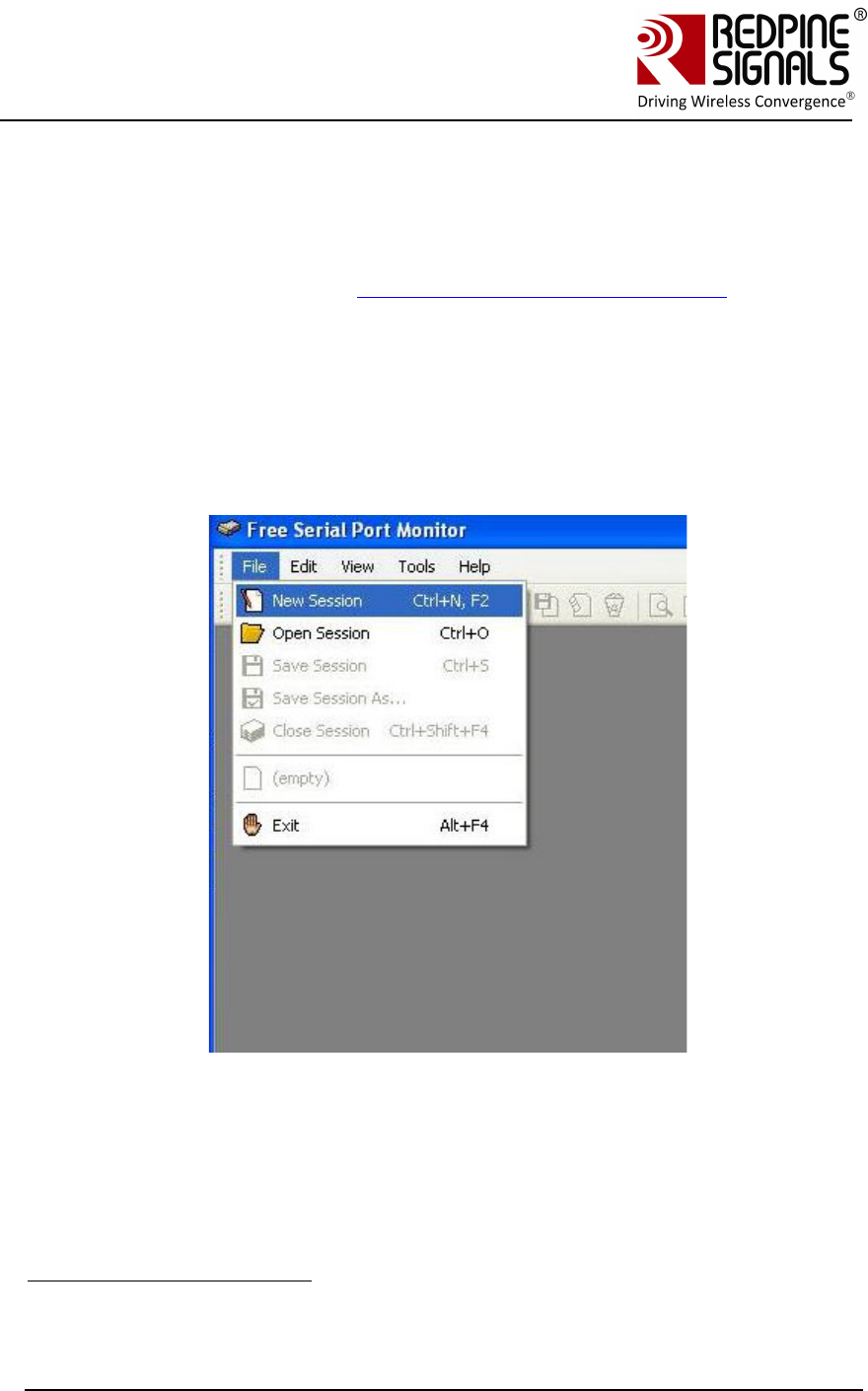
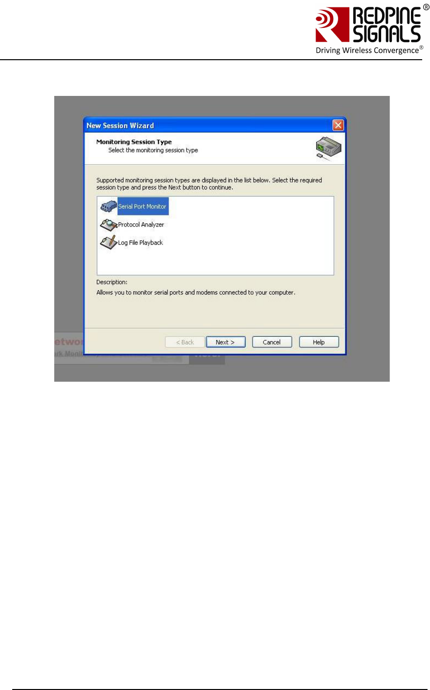
3.2 Configure Serial Port Monitor in the PC
The actual bytes exchanged between the module and the Host PC may
not all be readable on Hyperterminal or Teraterm because of ASCII
conversion. A serial port monitor2 can be used to see the actual bytes. A
free package is available at http://www.serial-port-monitor.com/ , while
other similar software such as Hterm, Docklight etc. also provide good
interfaces to simultaneously view ASCII and actual bytes exchanged in
the UART interface. The following sections assume that HHD Free Serial
Port Monitor has been installed from the above link.
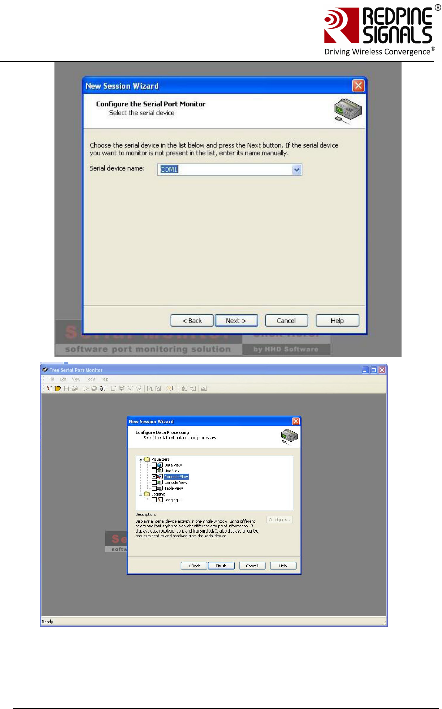
Open the “HHD Free Serial Port Monitor” BEFORE opening the
Hyperterminal or Teraterm. Click on File -> New Session. Select “Serial
Port Monitor”. Select the appropriate COM port and “Request view” for
the display format.
2 Redpine Signals Inc. assumes no liability for damages of any kind resulting from
use of third party software.
Redpine Signals, Inc. Page 15
Connect
-
io
-
n™
RS9110-N-11-24
Evaluation Board User Guide
V
V
e
e
r
r
s
s
i
i
o
o
n
n
3
3
.
.
1
1
3
3
Redpine Signals, Inc. Page 16
Connect
-
io
-
n™
RS9110-N-11-24
Evaluation Board User Guide
V
V
e
e
r
r
s
s
i
i
o
o
n
n
3
3
.
.
1
1
3
3
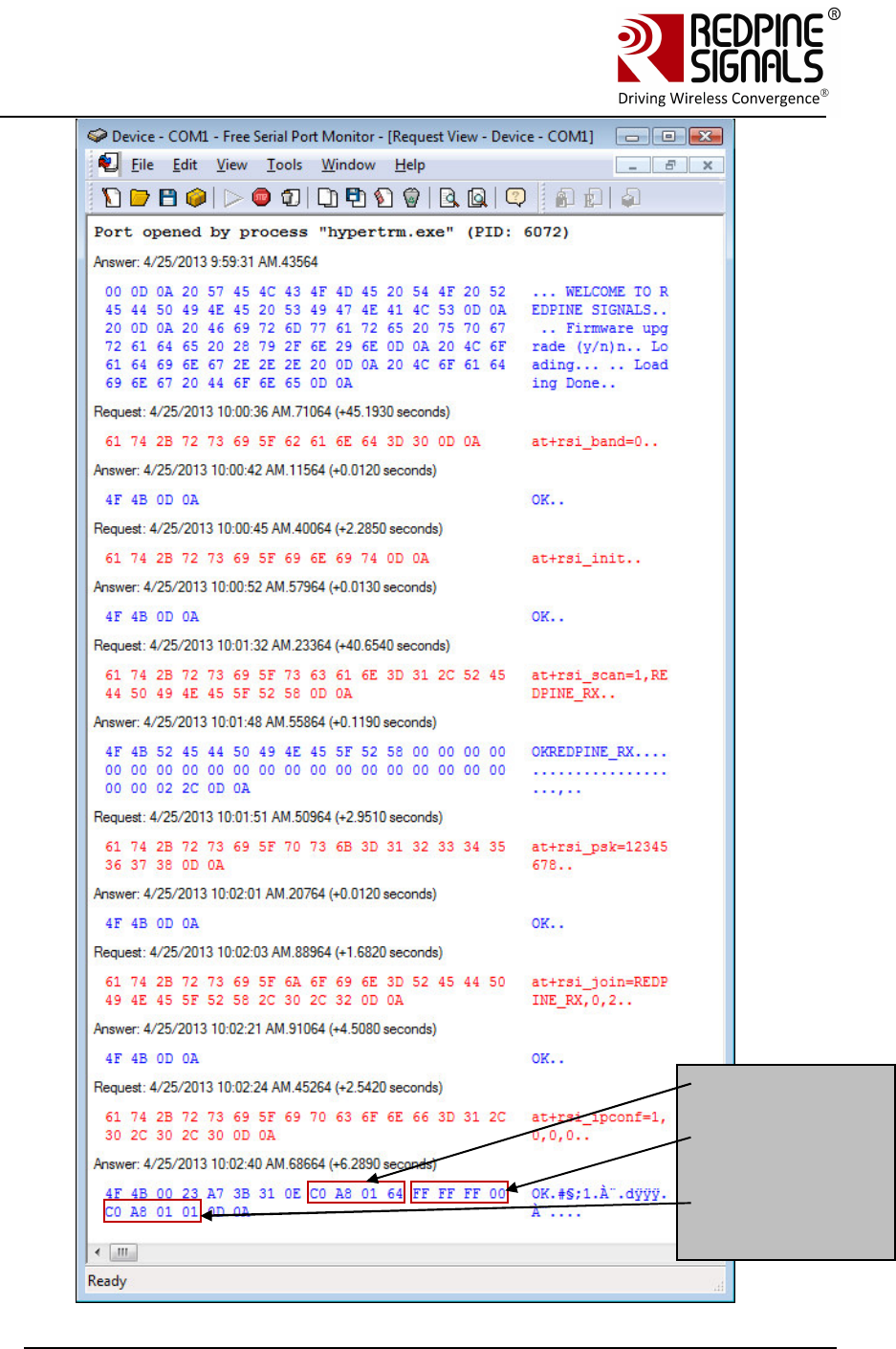
All bytes exchanged through the UART interface will now be visible on the
monitor.
Redpine Signals, Inc. Page 17
Connect
-
io
-
n™
RS9110-N-11-24
Evaluation Board User Guide
V
V
e
e
r
r
s
s
i
i
o
o
n
n
3
3
.
.
1
1
3
3
IP Address:
192.168.1.100
Subnet:
255.255.255.0
Gateway:
192.168.1.1
Redpine Signals, Inc. Page 18
Connect
-
io
-
n™
RS9110-N-11-24
Evaluation Board User Guide
V
V
e
e
r
r
s
s
i
i
o
o
n
n
3
3
.
.
1
1
3
3
3.3 Evaluating the Module in Infrastructure mode
The following sections describe the steps to evaluate the modules in
Infrastructure mode.
3.3.1 Configuration and Test Procedure
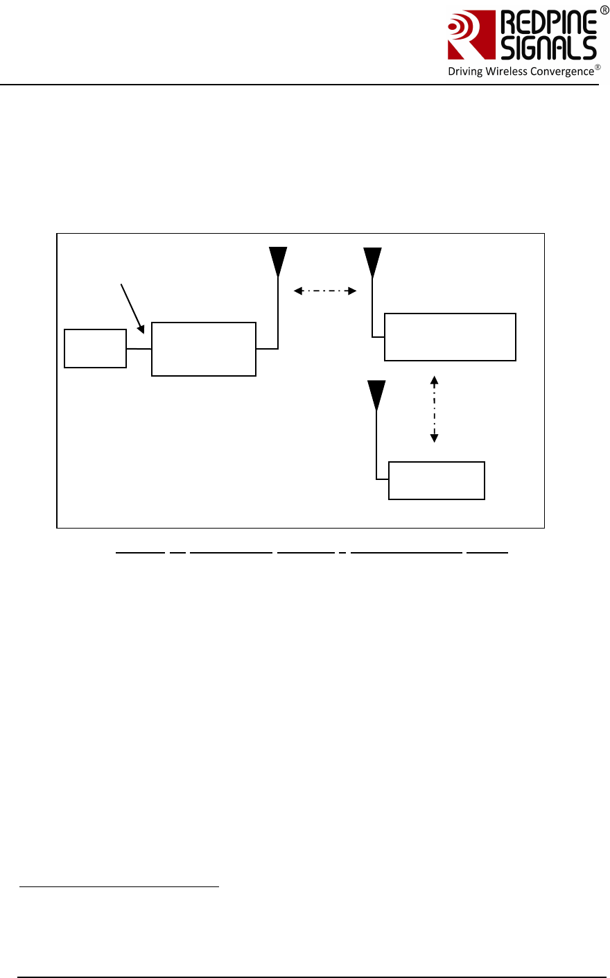
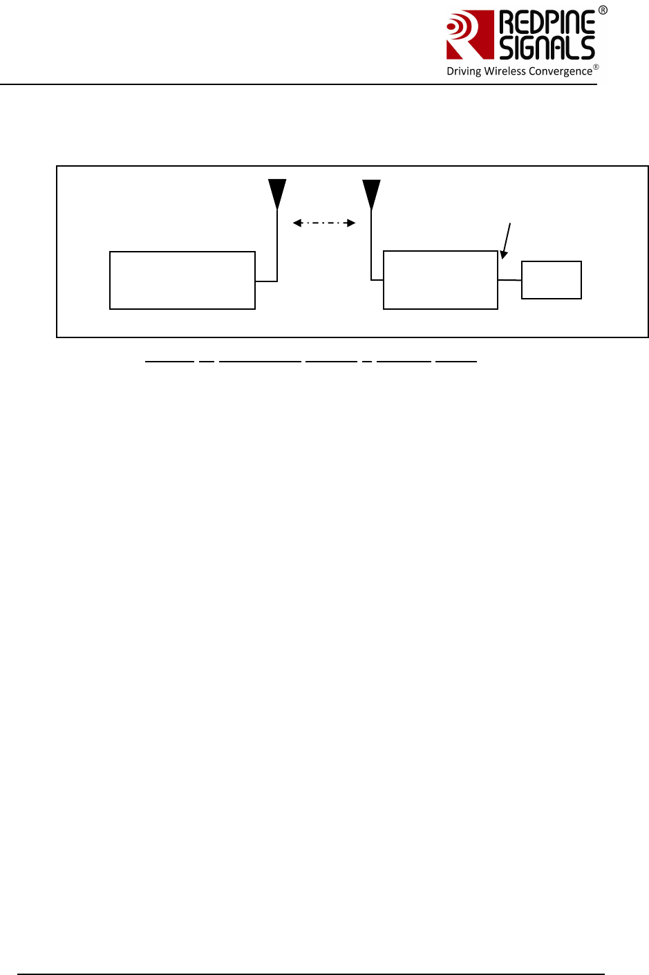
Figure 1: Evaluation Set-up3 - Infrastructure Mode
1. Configure the EVB in UART mode and connect a UART cable4 between the PC
and the EVB. Switch SW4 and SW5 should be set to select the DB9 connector.
Configure an Access Point (AP) accordingly.
2. Supply power to the EVB and put on the power switch.
3. The message “Firmware upgrade (y/n)” comes in the screen. Press ‘n’ and then
“Enter” key immediately.
4. Once “Loading Done” message comes, the following commands should be
issued.
a. at+rsi_band=0
This configures the operating band of the module to 2.4 GHz. If a
RS9110-N-11-28-EVB, that is capable of operating over 5 GHz, is
used, a band value of 1 can be issued to configure the module at 5
GHz.
b. at+rsi_init
This initializes the module
3 It is assumed for illustrative purposes that the IP of the AP is 192.168.50.1
4 USB-to-UART converter cables are found to not work consistently. It is advised to
use a UART cable.
PC
(P)
RS9110-N-
11-24
UART
Interfac
Access Point (B)
SSID=TEST_AP
Laptop (C)

Redpine Signals, Inc. Page 19
Connect
-
io
-
n™
RS9110-N-11-24
Evaluation Board User Guide
V
V
e
e
r
r
s
s
i
i
o
o
n
n
3
3
.
.
1
1
3
3
c. at+rsi_fwversion?
This returns the firmware version in the module.
d. at+rsi_scan=0
This command makes the module scan for all channels.
e. at+rsi_authmode=3
This command sets the security mode for the module to WPA2-
PSK.
f. at+rsi_psk=12345678
This command configures the PSK in the module to match that in
the Access Point (AP). It is assumed in this example that a WPA2-
PSK enabled AP is used, with a key “12345678”.
g. at+rsi_join=TEST_AP,0,2
This command is to associate to the Access Point “TEST_AP”
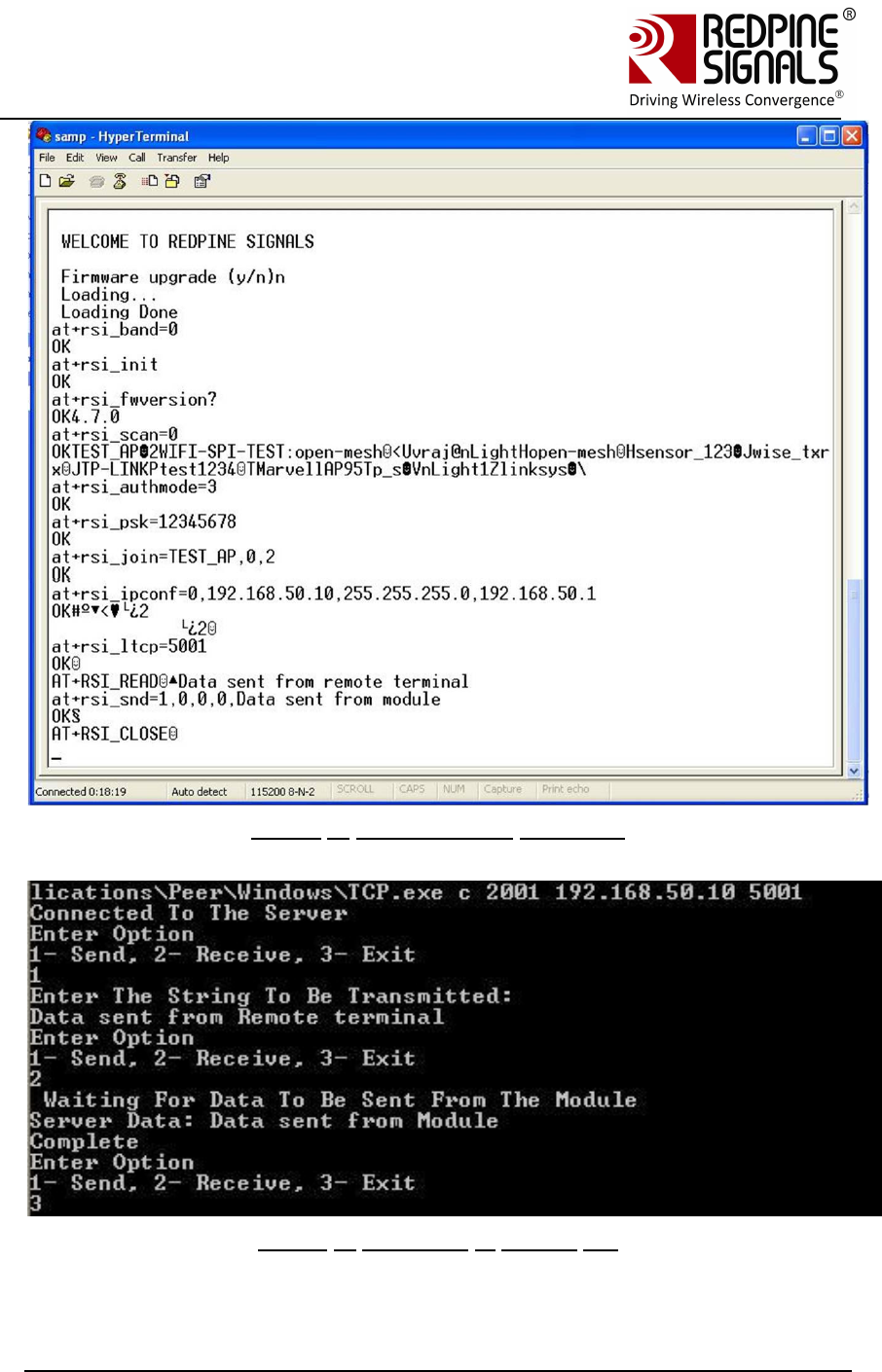
h. at+rsi_ipconf=0,192.168.50.10,255.255.255.0,192.168.
50.1
This command configures the module’s IP to 192.168.50.10 in
static mode. Make sure the desired IP is in the same subnet as
the Access Point. The module responds to this command by
sending the configured IP address to the Host as response to
the command. In Hyperterminal, this response might appear as
unreadable characters because of ASCII conversion. Serial Port
Monitoring software can however be used to see the exact
bytes. To get the IP in DHCP mode the command is
at+rsi_ipconf=1,0,0,0
It is assumed in the following sections that an IP of
192.168.50.10 has been assigned.
i. at+rsi_ltcp=5001
This command opens a listening TCP socket in the module
5. Connect Laptop (C) to the same Access Point and execute ping from it to the
module to check basic connectivity.
6. Exchanging data between the PC (P) and Laptop (C)
a. Open a TCP socket in the Laptop (C) by typing the below
command in the Windows command line interface. Make sure that
any firewalls, that might prevent opening of sockets, are disabled.
TCP.exe c 2001 192.168.50.10 5001
The application is found in the path
RS.CN.xx.GENR.UT.x.x.x\Software\Applications\Windows.
b. The command line window will display three options: 1 (Send), 2
(Receive) and 3 (Exit). Type 1 to send data to the Wi-Fi module.
On being prompted “Enter the string to be Transmitted”, type any

Redpine Signals, Inc. Page 20
Connect
-
io
-
n™
RS9110-N-11-24
Evaluation Board User Guide
V
V
e
e
r
r
s
s
i
i
o
o
n
n
3
3
.
.
1
1
3
3
string from the Keyboard (“Data sent from Remote terminal” in
this example). On pressing “Enter” key on the keyboard, the data
is sent from the Laptop (C) to the module and the terminal
displays it with the AT+RSI_READ message.
c. To send data from the Wi-Fi module, first type Option 2 in Laptop
C and then type the below command in the module
at+rsi_snd=1,0,0,0,Data sent from Module
The first parameter in the command is the socket_handle. It is 1
in this case. It is returned as the response of the command
at+rsi_ltcp and can be observed in Serial Port Monitor software.
Refer to the Programming Reference Manual for more details. The
data sent will be displayed in the Laptop C. If the application in
Laptop (C) is exited, the corresponding TCP socket closes and a
message AT+RSI_CLOSE is sent by the module to the Host PC5.
Usage of PC applications:
TCP.exe <s for server> <lport> <dipaddr> <dport>
TCP.exe <c for client> <lport> <dipaddr> <dport>
s – to open a server TCP socket
c – to open a client TCP socket
lport – Local port number
dipaddr – IP address of the destination
dport – Port number of the destination
UDP.exe is also used in the same way.
5 Refer to the Software Programming Reference Manual for details on the
commands and module behavior.
Redpine Signals, Inc. Page 21
Connect
-
io
-
n™
RS9110-N-11-24
Evaluation Board User Guide
V
V
e
e
r
r
s
s
i
i
o
o
n
n
3
3
.
.
1
1
3
3
Figure 2: Hyperterminal Messages
Figure 3: Messages in Laptop (C)
.

Redpine Signals, Inc. Page 22
Connect
-
io
-
n™
RS9110-N-11-24
Evaluation Board User Guide
V
V
e
e
r
r
s
s
i
i
o
o
n
n
3
3
.
.
1
1
3
3
Note: The above sequence of command can be executed by a Python script as well.
A sample Python script is provided at
RS.CN.xx.GENR.UT.x.x.x\Software\Applications\Python\ . The script configures the
module to associate to an Access Point with SSID “TEST_AP” and acquire an IP as a
DHCP client. The user can build upon this script.
1. Power on the module. Wait for about 20 secs for the ABRD (auto baud-rate
detection) process to be over.
2.Run the Python script in a Windows PC connected to the EVB through UART.
Redpine Signals, Inc. Page 23
Connect
-
io
-
n™
RS9110-N-11-24
Evaluation Board User Guide
V
V
e
e
r
r
s
s
i
i
o
o
n
n
3
3
.
.
1
1
3
3
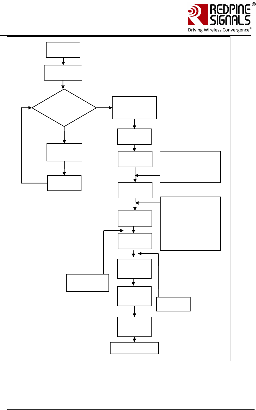
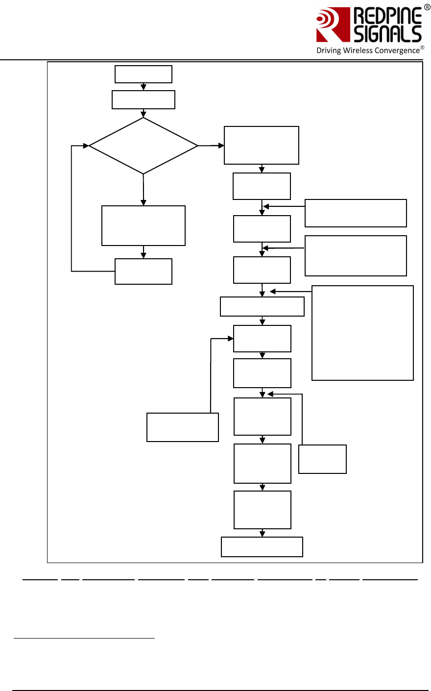
Figure 4: General Sequence of Commands
Firmware
Upgrade?
Power
up
Yes
No
Upgrade
the
firmware
Reset
module
ABRD
Band
comman
d
Init
comman
d
Scan
comman
d
Join
comman
d
IP
configur
e
Socket
opening
comman
Send
and
receive
Close
socket
comman
Disassociate
Wait 100ms
for booting to
complete
(Optional)
at+rsi_numscan
at+rsi_passscan
at+rsi_feat_sel
at+rsi_fwversion?
(Optional)
at+rsi_nextscan
at+rsi_bssid
at+rsi_nwtype
at+rsi_network
at+rsi_authmode
at+rsi_psk (if operating
in security mode)
at+rsi_sleeptimer
at+rsi_pwmode
(optional)
at+rsi_dnsserver
(optional)
at+rsi_dnsg
et
Redpine Signals, Inc. Page 24
Connect
-
io
-
n™
RS9110-N-11-24
Evaluation Board User Guide
V
V
e
e
r
r
s
s
i
i
o
o
n
n
3
3
.
.
1
1
3
3
3.4 Evaluating the Modules in Ad-hoc mode
Figure 5: Evaluation Set-up – Ad-hoc Mode
1. Configure the EVB in UART mode and connect a UART cable between the PC
and the EVB. Switch SW4 and SW5 should be set to select the DB9 connector.
Supply power to the RS9110-N-11-24 EVB and switch on the power.
2. After powering on the module, the message “Firmware upgrade (y/n)” comes in
the screen. Press ‘n’ and “Enter” key immediately.
3. Once “Loading Done” message comes, the following commands should be
issued in PC (D).
a. at+rsi_band=0
This configures the operating band of the module.
b. at+rsi_init
This initializes the module.
c. at+rsi_network=IBSS_SEC,1,6
This is to create an Ad-hoc network in channel 6 with WEP security.
d. at+rsi_psk=ABCDE12345
This configures the PSK of the network.
e. at+rsi_join=RSI_IBSS,0,2
This creates an open IBSS network with SSID “RSI_IBSS” that
other Wi-Fi devices can scan.
f. at+rsi_ipconf=0,192.168.1.10,255.255.255.0,192.168.1.1
This configures the IP address of the module.
4. Connect Laptop (A) to the Ad-hoc network and assign the static IP in same
subnet e.g. 192.168.1.11. Execute ping from it to the module’s IP address
to check basic connectivity.
Laptop (A) Joiner
192.168.1.180(pref
erably Windows)
UART
Interfac
RS module
(C) IBSS
creator
192.168.1.17
PC
(D)

Redpine Signals, Inc. Page 25
Connect
-
io
-
n™
RS9110-N-11-24
Evaluation Board User Guide
V
V
e
e
r
r
s
s
i
i
o
o
n
n
3
3
.
.
1
1
3
3
5. Exchanging data between the Wi-Fi module and Laptop (A)
a. Open a server TCP socket in the module
a+rsi_ltcp=5001
b. Open a TCP socket in the Laptop (A) by typing the below
command in the Windows command line interface. Make sure
that any firewalls, that might prevent opening of sockets, are
disabled.
TCP.exe c 2001 192.168.50.10 5001
The application is found in the path
RS.CN.xx.GENR.UT.x.x.x\Software\Applications\Windows\.
c. The command line window will display three options: 1 (Send),
2 (Receive) and 3 (Exit). Type 1 to send data to the Wi-Fi
module. On being prompted “Enter the string to be
Transmitted”, type any string from the Keyboard. On pressing
“Enter” key, the data is sent from the Laptop (A) to the module
and the terminal displays it with the AT+RSI_READ message.
d. To send data from the Wi-Fi module, first type Option 2 in
Laptop (A) and then type the below command in the module
at+rsi_snd=1,0,0,0,Data sent from Module
The first parameter in the command is the socket_handle. It is 1
in this case. It is returned as the response of the command
at+rsi_ltcp and can be observed in Serial Port Monitor software.
The data sent will be displayed in the Laptop (A).
NOTE: All bytes sent by the module to the Host PC may not be readable because
HyperTerminal converts some bytes into unreadable ASCII characters. There are
several applications similar to HyperTerminal and available online that can be used
to issue AT commands and also view the actual bytes returned by the module to
the Host. Such applications may be used instead of HyperTerminal to operate the
module using a PC.
3.5 Upgrading Firmware
There are two options for firmware upgrade:
Firmware upgrade without wireless firmware upgrade feature
Firmware upgrade with wireless firmware upgrade feature.6
The detailed procedure for firmware upgrade is mentioned in the below
sections.
3.5.1 Firmware Upgrade Using UART Interface without wireless firmware
upgrade feature
When the module is powered up, the following sequence is executed
6 Wireless firmware upgrade feature is not supported in RS9110-N-11-24 only
Redpine Signals, Inc. Page 26
Connect
-
io
-
n™
RS9110-N-11-24
Evaluation Board User Guide
V
V
e
e
r
r
s
s
i
i
o
o
n
n
3
3
.
.
1
1
3
3
1. Auto Baud Rate Detection
2. The module sends the message:
<space>WELCOME TO REDPINE SIGNALS\r\n<space>\r\n<space>
Byte sequence 0x20 0x57 0x45 0x4C 0x43 0x4F 0x4D 0x45 0x20 0x54 0x4F
0x20 0x52 0x45 0x44 0x50 0x49 0x4E 0x45 0x20 0x53 0x49 0x47 0x4E 0x41
0x4C 0x53 0x0D 0x0A 0x20 0x0D 0x0A 0x20
3. The module sends the message:
<space>Firmware upgrade (y/n)
Byte sequence 0x20 0x46 0x69 0x72 0x6D 0x77 0x61 0x72 0x65 0x20 0x75
0x70 0x67 0x72 0x61 0x64 0x65 0x20 0x28 0x79 0x2F 0x6E 0x29
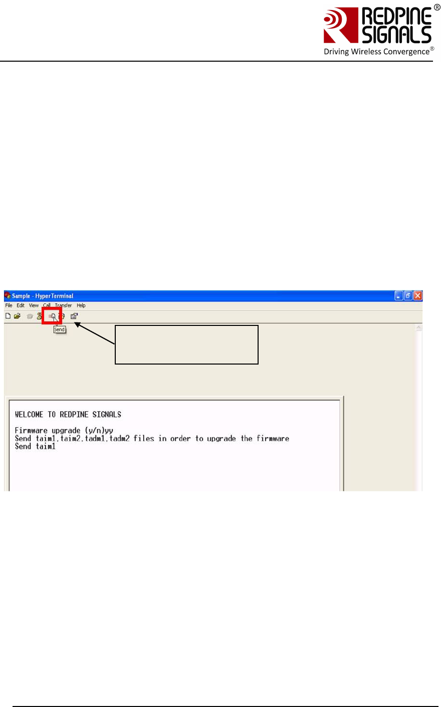
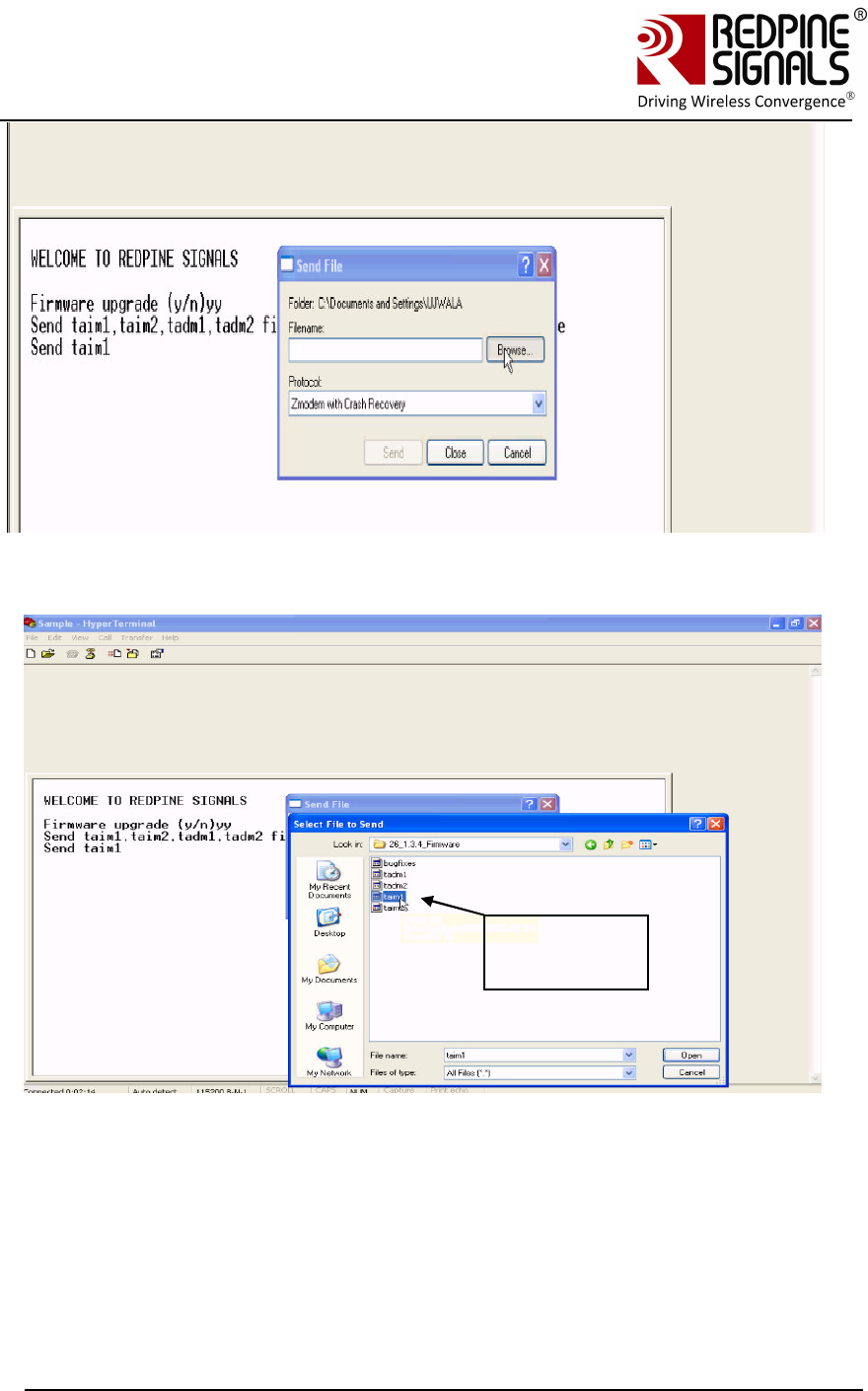
4. If the user wishes to upgrade firmware, ‘y’ (0x79) is sent to the module.
Click here to send files
for upgrade
Redpine Signals, Inc. Page 27
Connect
-
io
-
n™
RS9110-N-11-24
Evaluation Board User Guide
V
V
e
e
r
r
s
s
i
i
o
o
n
n
3
3
.
.
1
1
3
3
Select the firmware files from RS.CN.xx.GENR.UT.x.x.x\Software\Firmware\
Firmware
files
Redpine Signals, Inc. Page 28
Connect
-
io
-
n™
RS9110-N-11-24
Evaluation Board User Guide
V
V
e
e
r
r
s
s
i
i
o
o
n
n
3
3
.
.
1
1
3
3
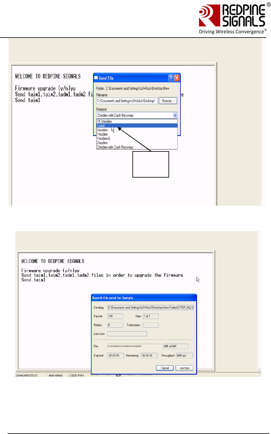
Select
Kermi
t
Redpine Signals, Inc. Page 29
Connect
-
io
-
n™
RS9110-N-11-24
Evaluation Board User Guide
V
V
e
e
r
r
s
s
i
i
o
o
n
n
3
3
.
.
1
1
3
3
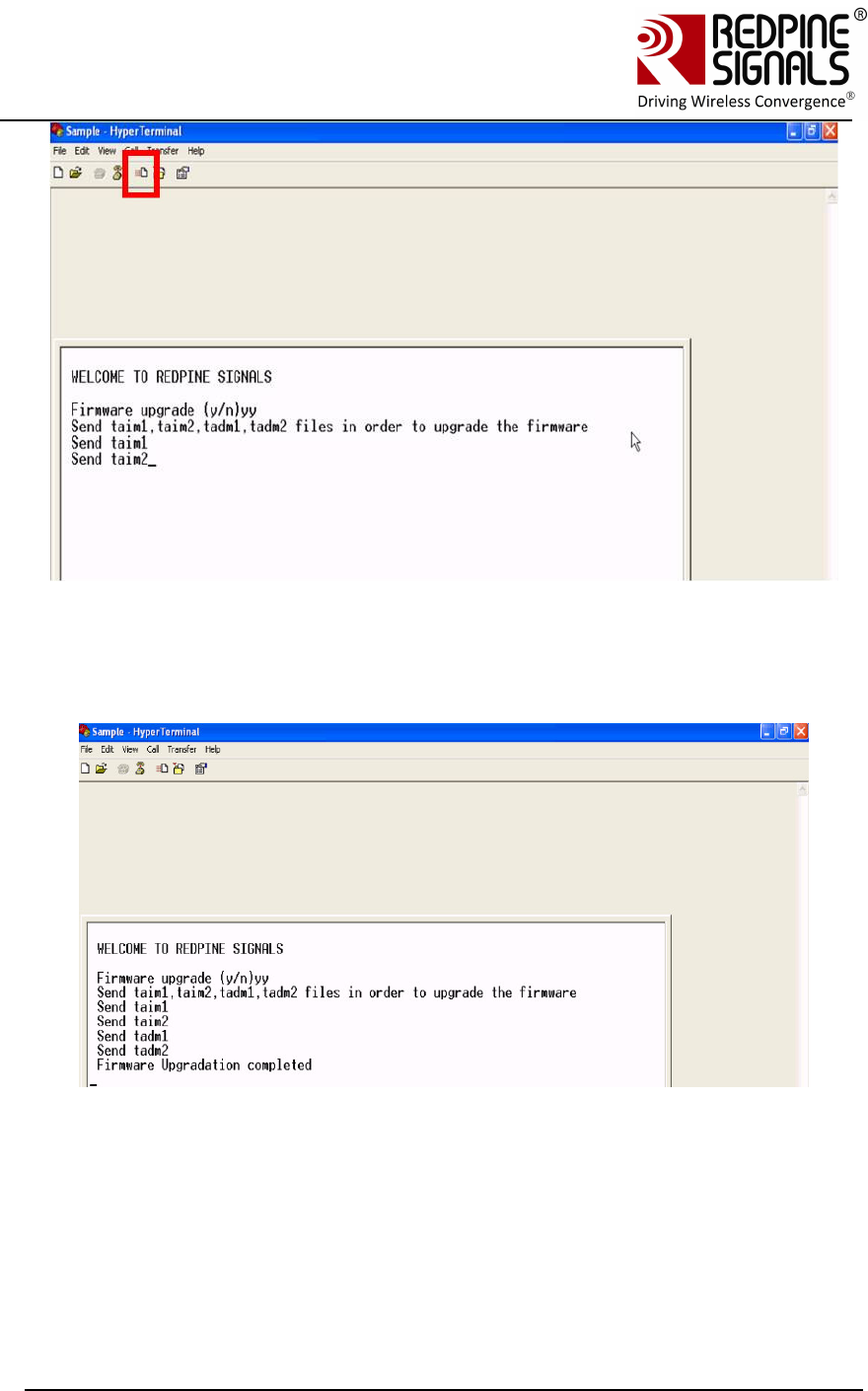
Follow the same sequence to load all the files from
RS.CN.xx.GENR.UT.4.7.x\Software\Firmware\ta*.
After all the files are loaded, the message “Firmware Upgradation
completed” is sent by the module.
<space>Firmware Upgradation completed\r\n
Byte sequence 0x20 0x46 0x69 0x72 0x6D 0x77 0x61 0x72 0x65 0x20 0x55
0x70 0x67 0x72 0x61 0x64 0x61 0x74 0x69 0x6F 0x6E 0x20 0x63 0x6F 0x6D
0x70 0x6C 0x65 0x74 0x65 0x64 0x0D 0x0A

Redpine Signals, Inc. Page 30
Connect
-
io
-
n™
RS9110-N-11-24
Evaluation Board User Guide
V
V
e
e
r
r
s
s
i
i
o
o
n
n
3
3
.
.
1
1
3
3
NOTE: Firmware upgrade need not be done every time the module is powered up.
It is only done when a new firmware is released for the product.
5. The user can now power cycle or hard reset the module and not opt for
firmware upgrade when “Firmware upgrade (y/n)” comes in the screen, by
sending ‘n\n’ (0x6E 0x0A) to the module immediately after the message
comes. In such a case, the following messages are sent from the module
<space>Loading…<space>\r\n
Byte sequence 0x20 0x4C 0x6F 0x61 0x64 0x69 0x6E 0x67 0x2E 0x2E 0x2E
0x20 0x0D 0x0A
<space>Loading Done\r\n
Byte sequence 0x20 0x4C 0x6F 0x61 0x64 0x69 0x6E 0x67 0x20 0x44 0x6F
0x6E 0x65 0x0D 0x0A
6. After this message, AT commands can be given as described
3.5.2 Firmware Upgrade Using UART Interface with wireless firmware
upgrade feature7’8
1. Open Hyperterminal and power up the module. The module sends the
message – “Firmware upgrade (y/n)”. Send ‘y’ to the module.
2. Send the files taim1, taim2, tadm1 and tadm2 from the location
RS.CN.xx.GENR.UT.4.7.x\Software\Wireless_Upgrade\Firstlevel_bootl
oader\ using the Kermit protocol. Follow the same process as
described in section Firmware Upgrade from a Lower Version to 4.7.x
Using UART Interface without wireless firmware upgrade feature to
load the file from the location
RS.CN.xx.GENR.UT.4.7.x\Software\Wireless_Upgrade\Firstlevel_bootl
oader\
3. Power cycle or hard reset the module. The module sends the message
– “Firmware upgrade (y/n)”. Send ‘n\n’ to the module immediately.
The module displays the messages “Loading…” and then
“1st level boot-loader upgradation completed”
Hex stream:
7 The first firmware version available for RS9110-N-11-24-04 is 4.7.1
8 Wireless Firmware Upgrade Feature is available from firmware version 4.7.X
onwards only.

Redpine Signals, Inc. Page 31
Connect
-
io
-
n™
RS9110-N-11-24
Evaluation Board User Guide
V
V
e
e
r
r
s
s
i
i
o
o
n
n
3
3
.
.
1
1
3
3
20 31 73 74 20 4C 65 76 65 6C 20 42 6F 6F 74 4C 6F 61 64 65 72 20
55 70 67 72 61 64 61 74 69 6F 6E 20 43 6F 6D 70 6C 65 74 65 64
0D 0A
4. Power cycle or hard reset the module. The module sends the
message – “Firmware upgrade (y/n)”. Send ‘y’ to the module.
5. On being prompted by the module, send taim1, taim2, tadm1 and
tadm2 from RS.CN.xx.GENR.UT.4.7.x\Software\Firmware\ta** to the
module. The module sends the message “Firmware Upgradation
completed”
6. Again power cycle or hard reset the module. The module sends the
message – “Firmware upgrade (y/n)”. Send ‘u’ to the module9. The
module prompts to send files sbim1, sbim2 and sbdm. Send these
files from RS.CN.xx.GENR.UT.4.7.x\Software\Wireless_Upgrade\
Secondlevel_bootloader\ in the same order, using the Kermit protocol.
For each file being transferred, wait for a display on the
HyperTerminal, which says “Send <nextfile>”. Note that after a file is
transmitted, there is some delay in writing the data to the non-volatile
memory. This might take a few seconds and the user has to wait for
the prompt on the HyperTerminal to send the next file.
7. After all the files are transferred, the message is sent by the module:
“2nd Level Bootloader Upgradation completed”
Hex stream:
20 32 6E 64 20 4C 65 76 65 6C 20 42 6F 6F 74 4C 6F 61 64 65 72
20 55 70 67 72 61 64 61 74 69 6F 6E 20 63 6F 6D 70 6C 65 74 65
64 20 0D 0A
8. Power cycle or hard reset the module. The module sends the message
– “Firmware upgrade (y/n)”. Send ‘s’ to the module10.
9. The module sends the message :
“Select one of the following option :
1.Configuration firmware upgrade:
2.Load configuration firmware :”
10. Enter ‘1’ immediately. Send files cfim1, cfim2 and cfdm1 from
RS.CN.xx.GENR.UT.x.x.x\Software\Wireless_Upgrade\Config_firmwar
e in the same order.
11. After the process is over, the module sends the message
“Configuration firmware upgrade completed”.
Hex stream:
9 Note that in the message “Firmware upgrade…”, ‘u’ is not displayed as an option.
10 Note that in the message “Firmware upgrade..”, ‘s’ is not displayed as an option

Redpine Signals, Inc. Page 32
Connect
-
io
-
n™
RS9110-N-11-24
Evaluation Board User Guide
V
V
e
e
r
r
s
s
i
i
o
o
n
n
3
3
.
.
1
1
3
3
20 63 6F 6E 66 69 67 75 72 61 74 69 6F 6E 20 66 69 72 6D 77 61 72
65 20 75 70 67 72 61 64 65 20 63 6F 6D 70 6C 65 74 65 64 20 0D
0A
This completes the upgrade process.
3.5.3 Firmware Upgrade from 4.7.x to a higher version Wirelessly
The module RS9110-N-11-24-04 can be upgraded wirelessly. Also, these
modules can be configured wirelessly to join specific access points. The
features of wireless configuration and wireless firmware upgrade are
available from firmware version 4.7.0 onwards.
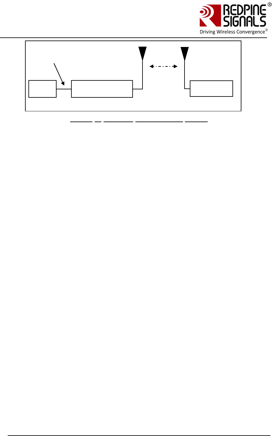
Figure 6: Wireless Firmware Upgrade Set-up
1. Power up the module. The module sends the message – “Firmware
upgrade (y/n)”. Send ‘s’ to the module11. The module sends two
options
1.Configuration Firmware upgrade
2.Load Configuration Firmware
Press 2. The module now becomes an Access Point with open mode
and SSID as REDPINE_<last 3 bytes of MAC ID of the module>
2. Connect Laptop (C) to the Access Point created by the module. The
Laptop will acquire an IP address from the AP.
3. Open the application
RS.CN.xx.GENR.UT.x.x.x\Software\Wireless_Upgrade\
DeviceConfigGUI.jar in Laptop (C).
11 Note that in the message “Firmware Upgrade…”, ‘s’ is not displayed as an option
PC
(P)
RS9110-N-11-24
UART
Interfac
Laptop (C)
Redpine Signals, Inc. Page 33
Connect
-
io
-
n™
RS9110-N-11-24
Evaluation Board User Guide
V
V
e
e
r
r
s
s
i
i
o
o
n
n
3
3
.
.
1
1
3
3
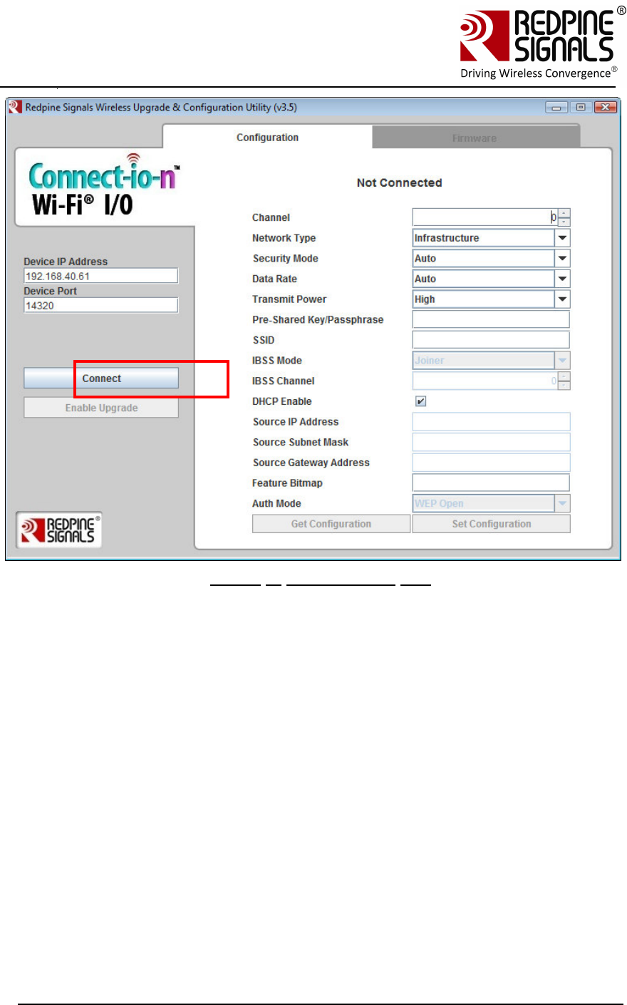
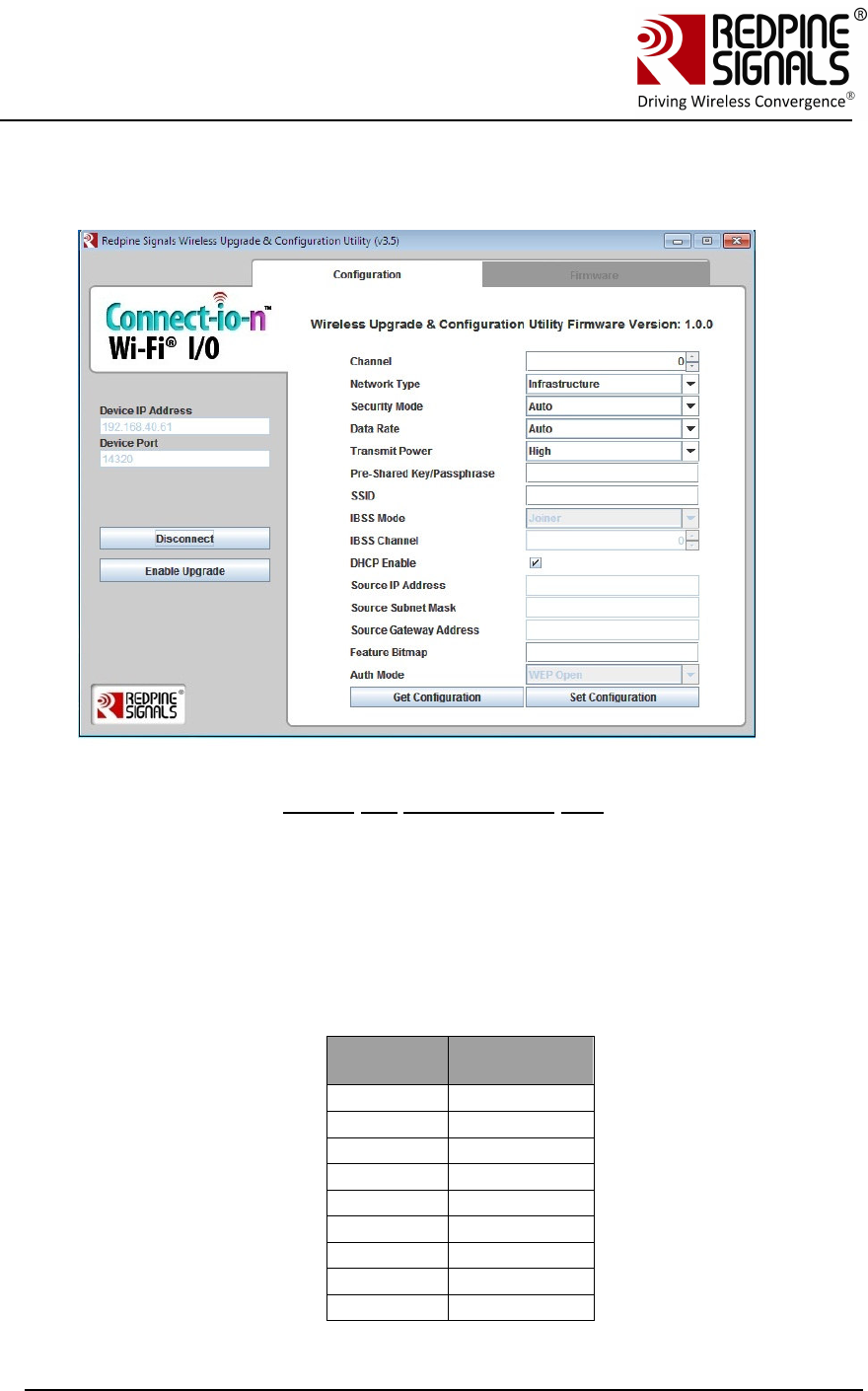
Figure 7: Configuration GUI
4. By default, the “Device IP Address” is 192.168.40.61 and “Device
Port” is 14320. Keep them unchanged and click “Connect”. This
makes the laptop establish a TCP socket connection with the AP. The
AP has an IP hardcoded into itself – 192.168.40.61. Ignore the values
on the right side of the GUI.
5. Click “Enable Upgrade” button and then click on the “Firmware” tab.
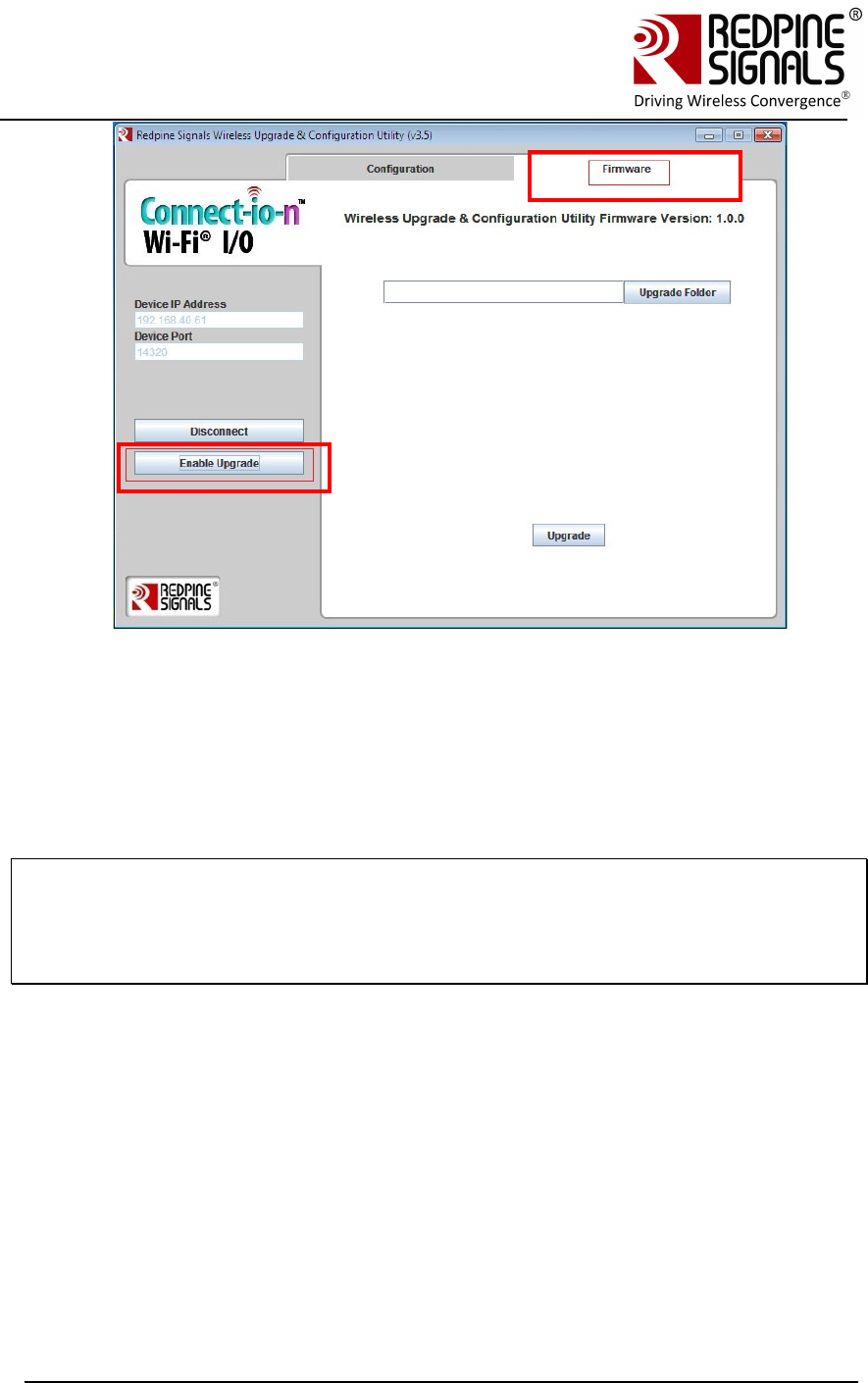
Redpine Signals, Inc. Page 34
Connect
-
io
-
n™
RS9110-N-11-24
Evaluation Board User Guide
V
V
e
e
r
r
s
s
i
i
o
o
n
n
3
3
.
.
1
1
3
3
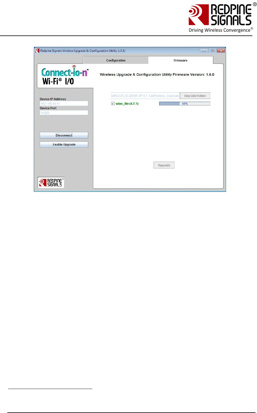
6. Click on “Upgrade Folder” and select the FOLDER
RS.CN.xx.GENR.UT.x.x.x\Software\Wireless_Upgrade\Functional_firm
ware\. Then click on the check box for the file wlan_file that appears
on the GUI. Click on “Upgrade” button.
NOTE: The file
RS.CN.xx.GENR.UT.x.x.x\Software\Wireless_Upgrade\Functional_firmware\wlan_fil
e.rps has the same contents as the files
RS.CN.xx.GENR.UT.x.x.x\Software\Firmware\ta**, but is formatted appropriately
for wireless upgrade
Redpine Signals, Inc. Page 35
Connect
-
io
-
n™
RS9110-N-11-24
Evaluation Board User Guide
V
V
e
e
r
r
s
s
i
i
o
o
n
n
3
3
.
.
1
1
3
3
7. The upgrade process starts. After successful upgrade, a message
“Upgrade Complete” is shown in the GUI. At the same time, the
message “AT+FWUPGRADE_DONE” is sent to the Host PC (P) from the
module through the UART interface. It can be seen on Hyperterminal.
8. The module is now upgraded with the latest firmware. It can be now
power cycled or hard reset and used in functional mode by providing
“n\n” as an answer to the module’s message “Firmware Upgrade
(y/n)”.
3.6 Using the Wireless Configuration Feature12
Using this feature, the module can be configured to
1. Join a specific Access Point
2. Join a specific ad-hoc network
3.6.1.1 Wireless Configuration in AP Mode
This section describes wireless configuration by putting the module initially
into Access Point mode. The next section describes wireless configuration
when the module is already connected to an AP.
12 Wireless configuration feature is not supported in RS9110-N-11-24 only
Redpine Signals, Inc. Page 36
Connect
-
io
-
n™
RS9110-N-11-24
Evaluation Board User Guide
V
V
e
e
r
r
s
s
i
i
o
o
n
n
3
3
.
.
1
1
3
3
Figure 8: Wireless Configuration Set-up
1. Power up the module. The module sends the message – “Firmware
upgrade (y/n)”. Send ‘s’ to the module. The module sends two
options: 1.Configuration Firmware upgrade
2.Load Configuration Firmware
2. Press ‘2’. The module now becomes an Access Point with open mode
and SSID REDPINE_<last 3 bytes of MAC ID of the module>.
3. Connect a Laptop (C) to the AP created by the module. The Laptop
should be configured as a DHCP client. The Laptop will acquire the IP
address from the AP.
4. Open the application
RS.CN.xx.GENR.UT.x.x.x\Software\Wireless_Upgrade\
DeviceConfigGUI.jar in Laptop (C) and click on the connect button.
Leave the “Device IP Address” and “Device Port” unchanged to
192.168.40.61 and 14320 respectively. After clicking on “Connect”
Button, click on the “Configuration” tab on top.
PC
(P)
RS9110-N-11-24
UART
Interfac
Laptop (C)
Redpine Signals, Inc. Page 37
Connect
-
io
-
n™
RS9110-N-11-24
Evaluation Board User Guide
V
V
e
e
r
r
s
s
i
i
o
o
n
n
3
3
.
.
1
1
3
3
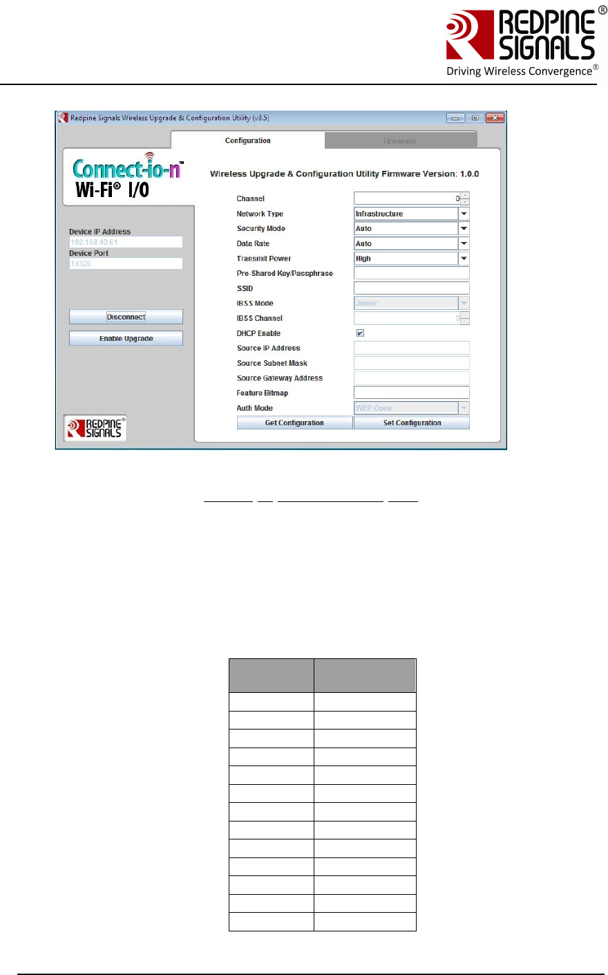
Figure 9: Configuration GUI
5. Click on the “Get Configuration” button. It displays the currently
stored configuration parameters. These parameters can be ignored for
now.
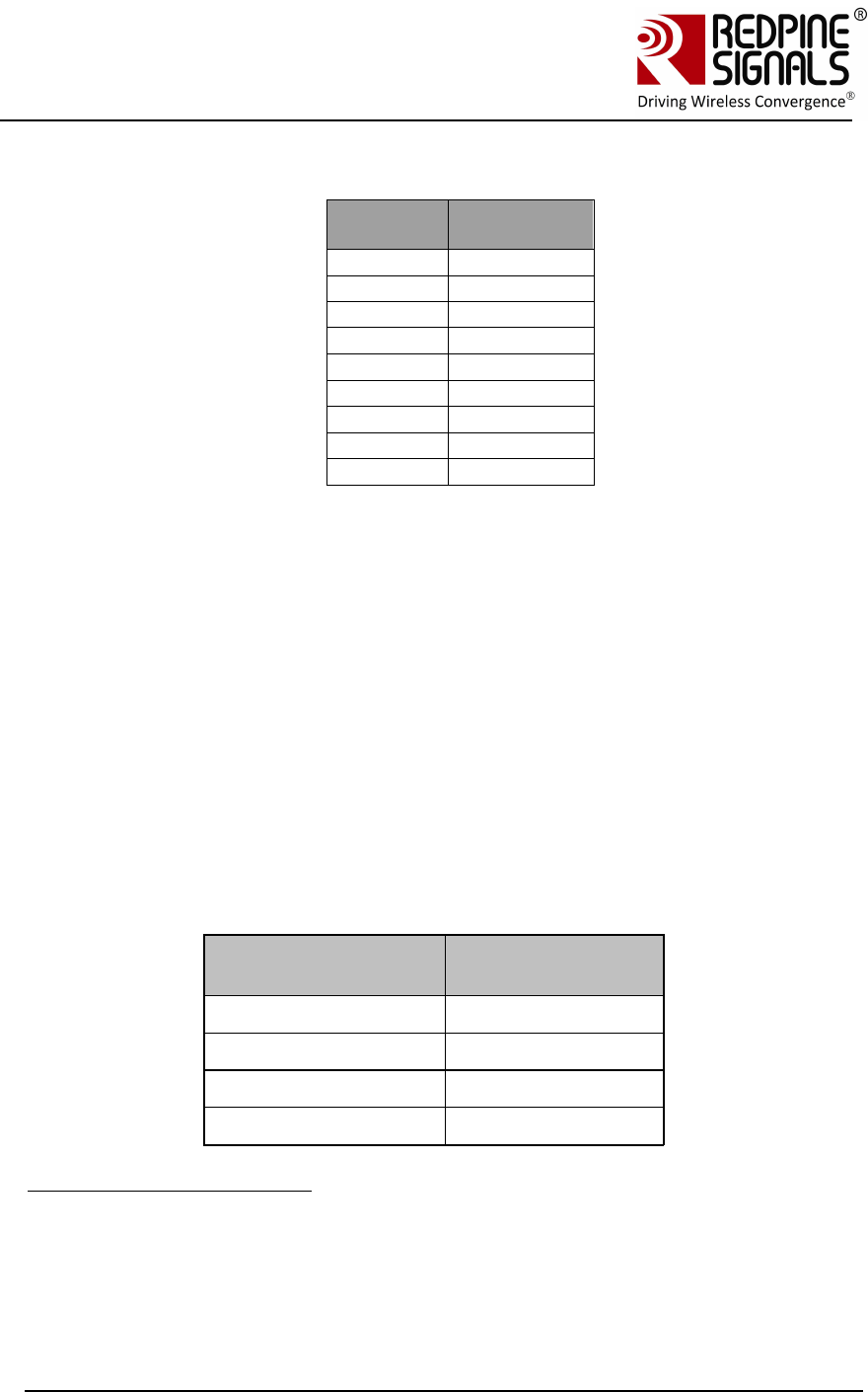
6. Fill the values of the parameters
a. Channel number of the AP or Adhoc network that the module
should connect to. Refer tables below:
For 2.4 GHz
Channel
Number
chan_num
parameter
1 1
2 2
3 3
4 4
5 5
6 6
7 7
8 8
9 9
10 10
11 11
12 12
13 13
Redpine Signals, Inc. Page 38
Connect
-
io
-
n™
RS9110-N-11-24
Evaluation Board User Guide
V
V
e
e
r
r
s
s
i
i
o
o
n
n
3
3
.
.
1
1
3
3
For 5 GHz
Channel
Number
chan_num
parameter
36 1
40 2
44 3
48 4
149 20
153 21
157 22
161 23
165 24
b. Network Type.
c. Security Mode- Security mode of the Access Point or Adhoc
network. This field has five options.
Open: Joins to an open network.
WPA: Joins to a WPA secured network.
WPA2: Joins to a WPA2 secured network.
WEP: Joins to a WEP secured network14.
Auto: Joins to a network irrespective of Security type,
provided the PreShared Key is correct15.
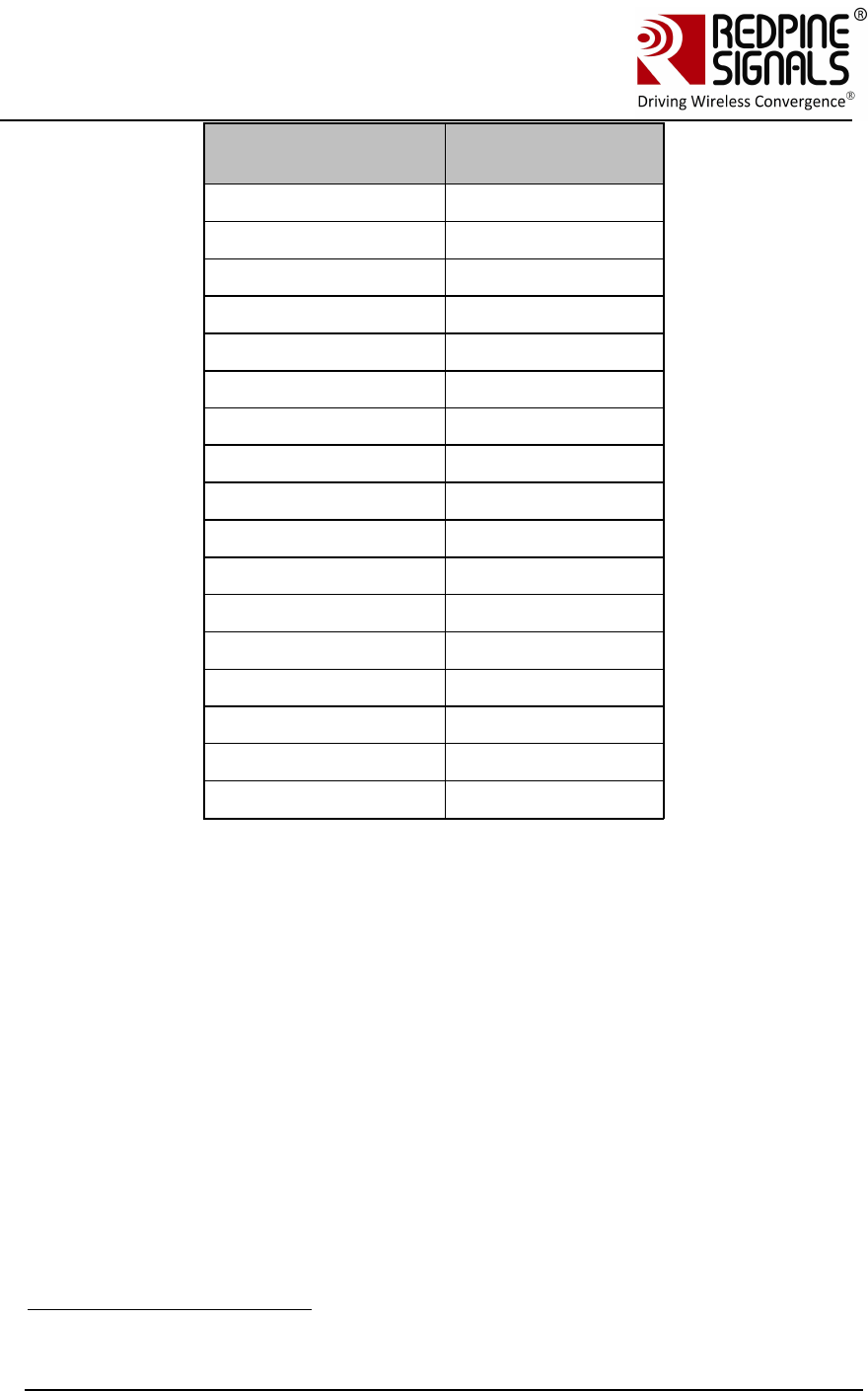
d. Data Rate- Physical data rate to be used.
Data Rate (Mbps) Value of Data
Rate
Auto-rate 0
1 1
2 2
5.5 3
14 If the AP is in WEP shared, fill Auth mode field with “WEP Shared” else if the AP
is in WEP open, leave the Auth mode field with “WEP Open”.
15 This will be useful in the scenario where the user doesn’t know in which Security
mode the AP is, but knows the Pre-shared key/WEP keys. This option can be used
when AP is Open/WEP Open/WPA/WPA2 security modes. This option cannot be
used when AP is in WEP shared Security mode.
Redpine Signals, Inc. Page 39
Connect
-
io
-
n™
RS9110-N-11-24
Evaluation Board User Guide
V
V
e
e
r
r
s
s
i
i
o
o
n
n
3
3
.
.
1
1
3
3
Data Rate (Mbps) Value of Data
Rate
11 4
6 5
9 6
12 7
18 8
24 9
36 10
48 11
54 12
MCS0 13
MCS1 14
MCS2 15
MCS3 16
MCS4 17
MCS5 18
MCS6 19
MCS7 20
e. Transmit Power.
f. Pre shared key- This can be left unfilled if the security mode is
“Open”.
g. SSID- This is the SSID of the Access Point or Ad-hoc network
to which the module should join.
h. IBSS mode (Ad-hoc)- Set it to “Joiner” if Network Type is
IBSS/IBSS Security16
i. IBSS Channel- This field can be ignored.
j. DHCP Enable/Disable- Used in infrastructure mode. For DHCP
enable it and disable it to assign Manual IP. In IBSS/IBSS
Security mode, this field would not be visible.
k. Source IP Address, Source Subnet Mask, Source Gateway
Address: If DHCP is disabled, an IP address, subnet mask and
gateway address should be entered for “Source IP Address”,
16 IBSS Creator is not supported

Redpine Signals, Inc. Page 40
Connect
-
io
-
n™
RS9110-N-11-24
Evaluation Board User Guide
V
V
e
e
r
r
s
s
i
i
o
o
n
n
3
3
.
.
1
1
3
3
“Source Subnet Mask” and “Source Gateway” respectively.
The module will get configured with these parameters.
l. Feature Bitmap- Set this field to ‘0’.
m. Auth mode- If “WEP” is selected in “Security Mode”, then the
options of “WEP Open” or “WEP Shared” should be used here.
7. Click on the button “Set Configuration”. The configuration information
is stored in non-volatile memory of the module and can be accessed
by the Host at any time using the at+rsi_cfgget command.
8. The GUI will send the message “Configure Success”. The module
sends the message “AT+REMOTE_CFG” to the Host17 PC (P). Once the
message is received, the module can be power cycled or hard reset.
The module sends the message – “Firmware upgrade (y/n)”. Send
“n/n” to the module. Now issue the command at+rsi_band to
configure the correct band of operation. After this command is issued,
the module will automatically join to the configured AP or Ad-hoc
network depending on the parameters entered in the above steps.
3.6.1.2 Wireless Configuration When the Module is Connected to an AP
The next section describes wireless configuration when the module is already
connected to an AP.
Figure 10: Wireless Configuration Set-up
1. Assuming the module is already connected to an AP through the
normal functional flow, connect a Laptop to the same AP.
2. Open the application
RS.CN.xx.GENR.UT.x.x.x\Software\Wireless_Upgrade\
DeviceConfigGUI.jar in Laptop (C) and click on the connect button.
17 The message is sent in uppercase alphabets
PC
(P)
RS
911
0
-
N
-
11
-
24
UART
Interfac
AP
Laptop (C)
Redpine Signals, Inc. Page 41
Connect
-
io
-
n™
RS9110-N-11-24
Evaluation Board User Guide
V
V
e
e
r
r
s
s
i
i
o
o
n
n
3
3
.
.
1
1
3
3
Enter the IP address of the module in the field “Device IP
Address”. Keep the “Device Port” unchanged to 14320. After
clicking on “Connect” Button, click on the “Configuration” tab on
top.
Figure 11: Configuration GUI
3. Click on the “Get Configuration” button. It displays the currently
stored configuration parameters. These parameters can be ignored
for now.
4. Fill the values of the parameters
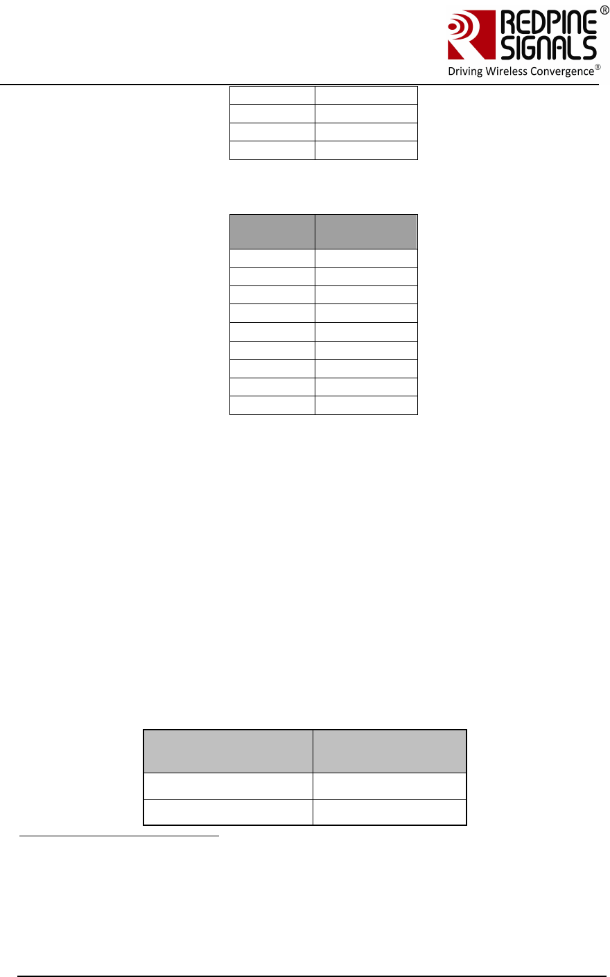
a. Channel number of the AP or Adhoc network that the
module should connect to. Refer tables below:
For 2.4 GHz
Channel
Number
chan_num
parameter
1 1
2 2
3 3
4 4
5 5
6 6
7 7
8 8
9 9
Redpine Signals, Inc. Page 42
Connect
-
io
-
n™
RS9110-N-11-24
Evaluation Board User Guide
V
V
e
e
r
r
s
s
i
i
o
o
n
n
3
3
.
.
1
1
3
3
10 10
11 11
12 12
13 13
For 5 GHz
Channel
Number
chan_num
parameter
36 1
40 2
44 3
48 4
149 20
153 21
157 22
161 23
165 24
b. Network Type.
c. Security Mode- Security mode of the Access Point or Adhoc
network. This field has five options.
Open: Joins to an open network.
WPA: Joins to a WPA secured network.
WPA2: Joins to a WPA2 secured network.
WEP: Joins to a WEP secured network18.
Auto: Joins to a network irrespective of Security type,
provided the PreShared Key is correct19.
d. Data Rate- Physical data rate to be used.
Data Rate (Mbps) Value of Data
Rate
Auto-rate 0
1 1
18 If the AP is in WEP shared, fill Auth mode field with “WEP Shared” else if the AP
is in WEP open, leave the Auth mode field with “WEP Open”.
19 This will be useful in the scenario where the user doesn’t know in which Security
mode the AP is, but knows the Pre-shared key/WEP keys. This option can be used
when AP is Open/WEP Open/WPA/WPA2 security modes. This option cannot be
used when AP is in WEP shared Security mode.
Redpine Signals, Inc. Page 43
Connect
-
io
-
n™
RS9110-N-11-24
Evaluation Board User Guide
V
V
e
e
r
r
s
s
i
i
o
o
n
n
3
3
.
.
1
1
3
3
Data Rate (Mbps) Value of Data
Rate
2 2
5.5 3
11 4
6 5
9 6
12 7
18 8
24 9
36 10
48 11
54 12
MCS0 13
MCS1 14
MCS2 15
MCS3 16
MCS4 17
MCS5 18
MCS6 19
MCS7 20
e. Transmit Power.
f. Pre shared key- This can be left unfilled if the security
mode is “Open”.
g. SSID- This is the SSID of the Access Point or Ad-hoc
network to which the module should join.
h. IBSS mode (Ad-hoc)- Set it to “Joiner” if Network Type is
IBSS/IBSS Security20
i. IBSS Channel- This field can be ignored.
j. DHCP Enable/Disable- Used in infrastructure mode. For
DHCP enable it and disable it to assign Manual IP. In
IBSS/IBSS Security mode, this field would not be visible.
20 IBSS Creator is not supported

Redpine Signals, Inc. Page 44
Connect
-
io
-
n™
RS9110-N-11-24
Evaluation Board User Guide
V
V
e
e
r
r
s
s
i
i
o
o
n
n
3
3
.
.
1
1
3
3
k. Source IP Address, Source Subnet Mask, Source Gateway
Address: If DHCP is disabled, an IP address, subnet mask
and gateway address should be entered for “Source IP
Address”, “Source Subnet Mask” and “Source Gateway”
respectively. The module will get configured with these
parameters.
l. Feature Bitmap- Set this field to ‘0’.
m. Auth mode- If “WEP” is selected in “Security Mode”, then
the options of “WEP Open” or “WEP Shared” should be used
here.
5. Click on the button “Set Configuration”. The configuration
information is stored in non-volatile memory of the module and
can be accessed by the Host at any time using the at+rsi_cfgget
command.
6. The GUI will send the message “Configure Success”. The module
sends the message “AT+REMOTE_CFG” to the Host21 PC (P). Once
the message is received, the module can be power cycled or hard
reset. The module sends the message – “Firmware upgrade
(y/n)”. Send “n/n” to the module. Now issue the command
at+rsi_band to configure the correct band of operation. After this
command is issed, the module will automatically join to the
configured AP or Ad-hoc network depending on the parameters
entered in the above steps.
NOTE: When the module is configured using wireless interface, the “Auto-join”
feature is enabled. This makes the module join to the configured AP on the next
power cycle or hard reset. If at any point of time, the user wants to disable the
“Auto-join” feature, the command (at+rsi_cfgneable=0) should be used.
3.7 General Operation of the Modules
21 The message is sent in uppercase alphabets
Redpine Signals, Inc. Page 45
Connect
-
io
-
n™
RS9110-N-11-24
Evaluation Board User Guide
V
V
e
e
r
r
s
s
i
i
o
o
n
n
3
3
.
.
1
1
3
3
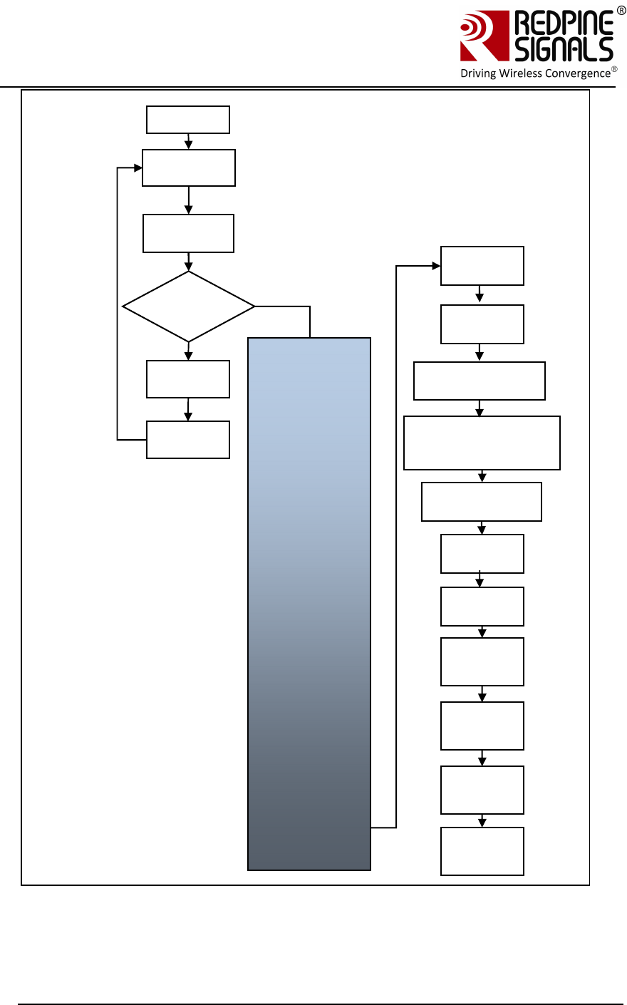
Figure 12: Firmware Upgrade and General Operation in UART modules22
22 An AT command should be given only after receiving a response from the Host
to the preceding command.
Firmware
Upgrade?
Power
Yes
No
Execute
Firmware
Upgrade
Process
Reset
module
ABRD
Band
comma
Init
comma
Scan
comma
Join
comma
IP
configu
re
Socket
opening
comma
nd
Send
and
receive
data
Close
socket
comma
nd
Disassociate
Wait 100ms
for booting
to complete
Optional:
at+rsi_numscan
at+rsi_passscan
Optional:
at+rsi_nextscan
at+rsi_bssid
at+rsi_nwtype
at+rsi_network
at+rsi_psk (if
operating in security
mode)
at+rsi_sleeptimer
at+rsi_pwmode
Optional:
at+rsi_dnsserv
er
Optional:
at+dnsget
Optional:
at+rsi_feat_sel
at+rsi_authmo
de
Redpine Signals, Inc. Page 46
Connect
-
io
-
n™
RS9110-N-11-24
Evaluation Board User Guide
V
V
e
e
r
r
s
s
i
i
o
o
n
n
3
3
.
.
1
1
3
3
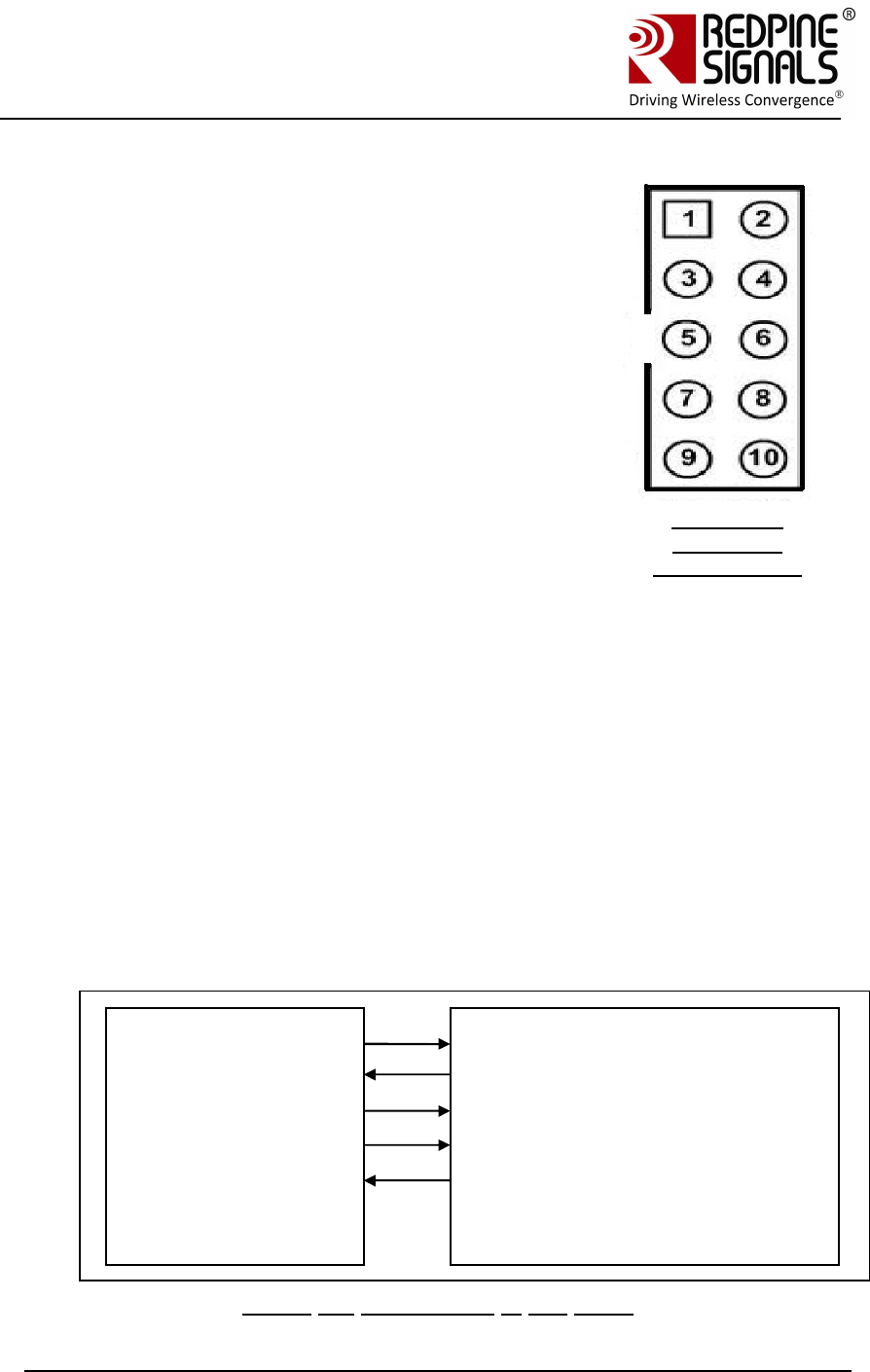
4 Using the Evaluation Board in SPI
mode
To use the EVB in the SPI mode, an MCU Host
platform must be interfaced with the module using
the SPI interface. The firmware package for the Wi-
Fi module comes with a reference driver in source
code form. The reference driver can be ported to the
Host MCU platform to interact and operate the Wi-Fi
module. The Programming Reference Manual (PRM)
is the most important document to help users to
operate the module in SPI mode. For
comprehensive details on all the SPI commands that
can be used to configure, operate and upgrade the
module, please refer to the Programming Reference
Manual. The set-ups used in the previous sections in
UART mode can be used in SPI mode as well.
Note: 1.There are two ways of powering the EVB:
either use the USB inlet (USB adapter provided with
the EVB) OR the pin #4 of the header.
2. Pin # 1 (SDIO_DATA3) should be left open.
3. Pin # 2 (SPI_CS) SPI chip Select
4. Pin # 3 VSS
5. Pin # 4 VDD
6. Pin # 5 (SPI_CLK) SPI Clock
7. Pin # 6 VSS
8. Pin # 7 SPI_DATAIN = MOSI
9. Pin # 8 SPI_DATAOUT = MISO
10. Pin # 9 The interrupt signal SPI_INTR is an active high signal.
11. Pin # 10 Not used.
Figure 13: Connections in SPI mode
Host MCU
SPI MOSI (SPI Header)
SPI MISO
(SPI Header)
SPI CLK
(SPI Header
SPI CS (SPI Header)
INTERRUPT
(SPI Header)
RS9110-N-11-
22/24/28
SPI
MOSI
SPI MISO
SPI CLK
SPI CS
INTERRUPT
Figure 16:
Header J7
SPI TOP View

Redpine Signals, Inc. Page 47
Connect
-
io
-
n™
RS9110-N-11-24
Evaluation Board User Guide
V
V
e
e
r
r
s
s
i
i
o
o
n
n
3
3
.
.
1
1
3
3
Signal Integrity Guidelines for SPI interface: Glitches in the SPI clock can
potentially take the SPI interface out of synchronization. The quality and integrity of
the clock line needs to be maintained. The following steps are recommended.
Please note that this is not an exhaustive list of guidelines and depending on
individual cases additional steps may be needed.
1. It is recommended to avoid using cables to connect the Host platform with the
module’s SPI interface. In case a cable is used, minimize the length of the SPI bus
cable to as small as possible, preferably to within an inch or two
2. It is recommended to use a companion card with a rigid connector to the host
3. If a cable is used, increase the number of ground connections between the WiFi
PCB and the MCU PCB
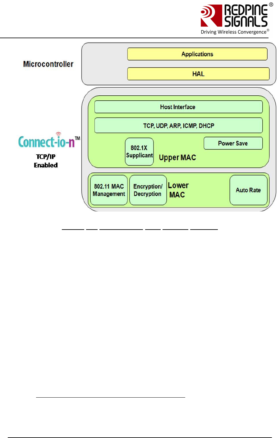
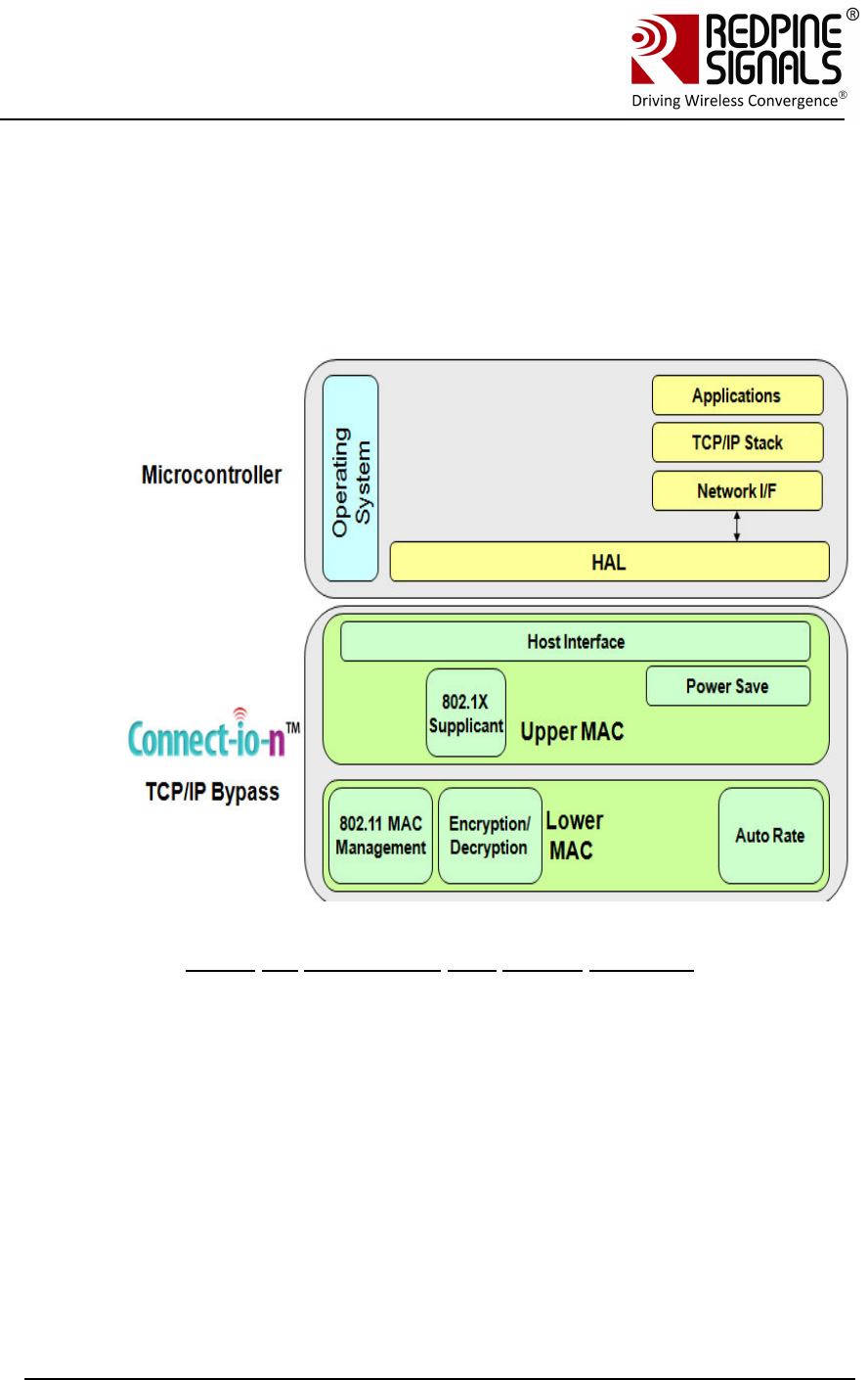
4.1 TCP/IP Stack Usage in RS9110-N-11-24–SPI mode
RS9110-N-11-22, RS9110-N-11-24 and RS9110-N-11-28 are Wi-Fi
modules with integrated TCP/IP stack. This reduces the development
effort for designers who don’t want to integrate a TCP/IP stack in their
Host platform. However, there are applications where the designer wants
to run his own TCP/IP stack on the Host. The TCP/IP stack in the
mentioned modules can be bypassed in such scenarios. This feature of
bypassing the stack is available from firmware version 4.5.0 onwards.
4.1.1 Using the Wi-Fi module with TCP/IP stack enabled
The Wi-Fi module is by default in “TCP/IP stack enabled” mode.
1. The reference driver that the user should use for this mode is placed
inside RS.CN.xx.GENR.SP.x.x.x/Driver/Driver_TCP
2. The API manual that should be used is placed in
RS.CN.xx.GENR.SP.x.x.x/Driver/Driver_TCP/Documentation/
Redpine Signals, Inc. Page 48
Connect
-
io
-
n™
RS9110-N-11-24
Evaluation Board User Guide
V
V
e
e
r
r
s
s
i
i
o
o
n
n
3
3
.
.
1
1
3
3
Figure 14: Architecture with TCP/IP Enabled
4.1.2 Using the Wi-Fi module with TCP/IP stack bypassed
The TCP/IP stack in the WiFi module can be bypassed by sending a
software command from the Host to the module.
The “TCP bypass command” should be issued to convert the RS9110-N-
11-24 from a TCP/IP enabled module to a TCP/IP bypassed module. The
following should be taken care of:
1. The reference driver that the user should use for this mode is placed
inside RS.CN.xx.GENR.SP.x.x.x/Driver/Driver_TCP_Bypass
2. The API manual that should be used is placed in
RS.CN.xx.GENR.SP.x.x.x/Driver/Driver_TCP_Bypass/Documentation/
3. In this mode, the WiFi module presents itself as a standard network
interface, which would talk to the Host TCP/IP stack through the network
driver in the Host. For transmitting data to the air interface, the data
should be framed by the TCP/IP stack in the Host as an Ethernet frame,
and the WiFi module does only the WLAN framing on top of it. The
interface is according to standard networking protocols. For example :
http://www.makelinux.com/ldd3/chp-17-sect-3 describes the structure for
Linux. For successful sending and receiving of data, the MAC ID of the
module should be assigned to a field inside the net_device structure
Redpine Signals, Inc. Page 49
Connect
-
io
-
n™
RS9110-N-11-24
Evaluation Board User Guide
V
V
e
e
r
r
s
s
i
i
o
o
n
n
3
3
.
.
1
1
3
3
dev_addr of the network driver on the Host OS. Once this is stored after
association with AP, the user can bring the wlan interface up
In Linux, this is usually done by:
ifconfig wlan0 <ipaddr>
ifconfig wlan0 up
The user can query wlan0 interface status using:
ifconfig wlan0
The Redpine Module’s MAC address should be listed in the HW Addr
(00:23:A7:xx:xx:xx)
Figure 15: Architecture with TCP/IP Bypassed
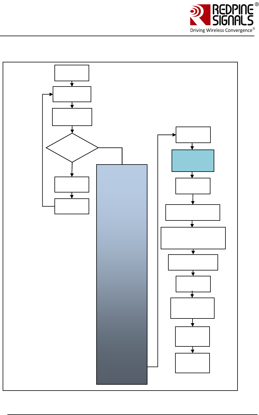
4.2 SPI Operations
The SPI operations with the TCP/IP stack enabled in the module are
shown below.
Redpine Signals, Inc. Page 50
Connect
-
io
-
n™
RS9110-N-11-24
Evaluation Board User Guide
V
V
e
e
r
r
s
s
i
i
o
o
n
n
3
3
.
.
1
1
3
3
Feature Select command can be issued before or after init command. To control
the boot up LED Feature Select command has to be issued before init command.
While for other features it can be issued after init command.
Image
Upgrad
e?
Power
up
N
o
Execute
firmware
upgrade
Reset
module
Load
sbinst1
Load
sbinst2
Load
sbdata1
Bring
module
out of
soft
Read
card
ready
indicatio
Load
sbdata2
Ready
for
general
operatio
SPI
interface
initializatio
Band
comman
d
Init
comman
d
Scan command (not
required if module is
Ad-hoc network
creator)
Join
comman
d
IP
configur
e
Socket
opening
comman
Send
and
receive
Close
socket
comman
Disconne
ct
comman
Soft reset
the
module
Y
e
Boot-load
process
Feature Select
Command
(optional)
Set PSK (if
operating
in security mode)
Redpine Signals, Inc. Page 51
Connect
-
io
-
n™
RS9110-N-11-24
Evaluation Board User Guide
V
V
e
e
r
r
s
s
i
i
o
o
n
n
3
3
.
.
1
1
3
3
The SPI operations with the TCP/IP stack disabled in the module are shown
below. In this mode, the module can be used with a Host that has its own TCP/IP
stack.
Image
Upgrad
e?
Power
up
N
o
Execute
Firmwar
e
Reset
module
Load
sbinst1
Load
sbinst2
Load
sbdata1
Bring
module
out of
soft
Read
card
ready
indicatio
Load
sbdata2
Ready
for
general
operatio
SPI
interface
initializatio
Band
comman
d
Init
comman
d
Scan command (not
required if module is
Ad-hoc network
creator)
Join
comman
d
Interface
configuration
at Host
Open
socket in
Host
Send
and
receive
Soft reset
the module
Y
e
Boot-load
process
Feature Select
Command
(optional)
Set PSK (if
operating
in security mode)
Issue TCP
Bypass
Command
<rsi_spi_mode_
select>

Redpine Signals, Inc. Page 52
Connect
-
io
-
n™
RS9110-N-11-24
Evaluation Board User Guide
V
V
e
e
r
r
s
s
i
i
o
o
n
n
3
3
.
.
1
1
3
3
For comprehensive details on all the SPI commands that can be used to
configure and operate the module, please refer to the Programming Reference
Manual.
NOTE: Writing code from a scratch to execute these sequences may be time
consuming. The user is strongly advised to use the API set, the source code of
which is provided with the software package inside
RS.CN.xx.GENR.SP.x.x.x/Driver/Driver_TCP<or nonTCP> , along with the PRM

Redpine Signals, Inc. Page 53
Connect
-
io
-
n™
RS9110-N-11-24
Evaluation Board User Guide
V
V
e
e
r
r
s
s
i
i
o
o
n
n
3
3
.
.
1
1
3
3
5 FCC and IC Declaration
This device complies with Part 15 of the FCC Rules.
Operation is subject to the following two conditions:
(1) This device may not cause harmful interference, and
(2) This device must accept any interference received, including interference that
may cause undesired operation.
NOTE: This equipment has been tested and found to comply with the limits for a
Class B digital device, pursuant to part 15 of the FCC Rules. These limits are
designed to provide reasonable protection against harmful interference when the
equipment is operated in a commercial environment. This equipment generates,
uses, and can radiate radio frequency energy and, if not installed and used in
accordance with the instruction manual, may cause harmful interference to radio
communications. Operation of this equipment in a residential area is likely to cause
harmful interference in which case the user will be required to correct the
interference at his own expense.
This Class B digital apparatus complies with Canadian ICES-003.
Cet appareil numérique de la classe A est conforme à la norme NMB-003 du
Canada.
This device complies with Industry Canada license-exempt RSS standard(s).
Operation is subject to the Following two conditions :( 1) this device may not
cause interference, and (2) This device
must accept any interference, including interference that may cause undesired
operation of the device.
Le présent appareil est conforme aux CNR d'Industrie Canada applicables aux
appareils radio exempts de licence.
L'exploitation est autorisée aux deux conditions suivantes : (1) l'appareil ne doit
pas produire de brouillage, et
(2) l'utilisateur de l'appareil doit accepter tout brouillage radioélectrique subi,
même si le brouillage est susceptibled'en compromettre le fonctionnement.
CAUTION: Any changes or modifications not expressly approved by the party
responsible for compliance could void the user’s authority to operate the
equipment.
This equipment should be installed and operated with minimum distance 20 cm
between the radiator & your body.
End Product Labelling
This Module is labelled with its own FCC ID. If the FCC ID Certification Number is
not visible while installed inside another device, then the device should display the
label on it referring the enclosed module. In that case, the final end product must
be labelled in a visible area with the following:
“Contains Transmitter Module FCC ID: XF6-RSWC201”
OR
“Contains FCC ID: XF6-RSWC201”
The OEM should not provide information to the end user regarding installation or
removal of this RF module or change RF related parameters in the user manual of
the end product.

Redpine Signals, Inc. Page 54
Connect
-
io
-
n™
RS9110-N-11-24
Evaluation Board User Guide
V
V
e
e
r
r
s
s
i
i
o
o
n
n
3
3
.
.
1
1
3
3
The OEM integrator is still responsible for testing their end-product for any
additional compliance requirements required with this module installed (for
example, digital device emissions, PC peripheral requirements, etc.).
énoncé de la FCC (états-Unis seulement) Cet équipement a été testé et jugé conforme aux
limites de Classe B pour un appareil numérique, en vertu de l’article 15 de la réglementation de
la FCC. Ces limites ont été instaurées our fournir une rotection raisonnable contre toute
interférence nuisible dans une installation résidentielle. Cet équipement génère, utilise et peut
émettre de l’énergie radiofréquence. S’il n’est pas installé et utilisé conformément aux
instructions, il peut provoquer des interférences sur les
communications radio. Cependant, il n’est pas garanti que des interférences ne se produiront
pas dans certaines installations. Si cet équipement cause des interférences à la reception radio
ou télévisée (ce qui peut être vérifi é en éteignant l’appareil puis en le remettant sous tension),
l’utilisateur peut enter de ésoudre en suivant une ou plusieurs des mesures ci-après :
Réorienter ou déplacer l’antenne réceptrice.
ugmenter l’espace entre l’appareil et le récepteur. Brancher l’appareil à une prise de courant
différente de celle sur laquelle le récepteur est branché. Pour obtenir de l’aide, contacter le
vendeur ou un technician radio/television expérimenté.
REMARQUE: Toute modifi cation non autorisée expressément par le fabricant responsable de
la
onformité peut annuler le droit de l’utilisateur à faire fonctionner le produit.
*****