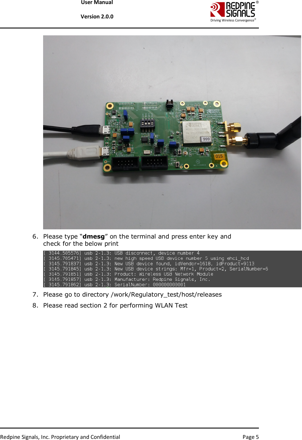
Silicon Labs RS9113DBH 802.11 abgn Wi-Fi module with high output power User Manual OEM Installation Manual

Redpine Signals Inc 802.11 abgn Wi-Fi module with high output power OEM Installation Manual

OEM Installation Manual

   Redpine Signals, Inc. Proprietary and Confidential               User Manual Version 2.0.0  July 2016 Redpine Signals, Inc. 2107 N. First Street, #680 San Jose, CA 95131. Tel: (408) 748-3385 Fax: (408) 705-2019  Email: info@redpinesignals.com Website: www.redpinesignals.com
  Redpine Signals, Inc. Proprietary and Confidential  Page 2 User Manual  Version 2.0.0  About this Document  This document describes the usage of the RS9113 n-Link® Driver for testing transmit & receive Regulatory Performance for Wi-Fi protocols.  Disclaimer:  The information in this document pertains to information related to Redpine Signals, Inc. products. This information is provided as a service to our customers, and may be used for information purposes only. Redpine assumes no liabilities or responsibilities for errors or omissions in this document.  This document may be changed at any time at Redpine’s sole discretion without any prior notice to anyone. Redpine is not committed to updating this document in the future. Copyright © 2016 Redpine Signals, Inc. All rights reserved.
  Redpine Signals, Inc. Proprietary and Confidential  Page 3 User Manual  Version 2.0.0  Table Of Contents  1 Introduction ...................................................................................................... 4 1.1 Getting Started .................................................................................................... 4 2 WLAN Performance Test Application Usage ..................................... 6 2.1 Transmit Tests...................................................................................................... 6 2.1.1 Transmit Command .................................................................................................... 7 2.1.2 Transmit Command Description.............................................................................. 7 2.1.3 Examples........................................................................................................................ 9 2.2 Receive Tests ...................................................................................................... 10 2.2.1 Receive Command .................................................................................................... 10 2.2.2 Receive Command Description .............................................................................. 10 2.2.3 Examples...................................................................................................................... 11 3 Instructions for integration of the host module .......................... 12 3.1 Trace layout and dimensions: .................................................................... 12 3.2 Manufacturer and specifications: ............................................................. 12 4 FCC Declaration ............................................................................................. 13  Table of Figures  No table of figures entries found.   Table of Tables  Table 1: Channel Numbers and Corresponding Center Frequencies .................... 8 Table 2: Rate Flags for Transmit Tests ................................................................................ 9 Table 3: Regulatory Domain Input in Transmit Tests .................................................. 9
  Redpine Signals, Inc. Proprietary and Confidential  Page 4 User Manual  Version 2.0.0 1 Introduction The software provided for the RS9113 n-Link® modules is named OneBox-Mobile. The software currently supports performance testing for Wi-Fi The subsequent sections explain the use of OneBox-Mobile software on an x86 platform. Installation and operation of the driver on specific representative processor platforms have been explained in the Appendix sections.  1.1 Getting Started 1. Login to user “test” with password “test123” 2. Open a Terminal 3. Type command “su” and press enter key 4. Enter password “test123” 5. Connect EUT to Laptop with USB cable as shown below
  Redpine Signals, Inc. Proprietary and Confidential  Page 5 User Manual  Version 2.0.0  6. Please type “dmesg” on the terminal and press enter key and check for the below print  7. Please go to directory /work/Regulatory_test/host/releases 8. Please read section 2 for performing WLAN Test
  Redpine Signals, Inc. Proprietary and Confidential  Page 6 User Manual  Version 2.0.0 2 WLAN Performance Test Application Usage The OneBox-Mobile software provides applications to test Transmit and Receive performance of the module. The Band of operation of the module needs to be configured before performing any tests.   NOTE: Open the common_insert.sh file present in the “release” folder using an editor like vim. Ensure that the DRIVER_MODE is set as below: DRIVER_MODE = 2 COEX_MODE = 1 Run the following command to install the Driver in Performance Test mode: # sh wlan_insert.sh Please type “dmesg” in the terminal and press enter key and check for the below print for check if driver has been loaded properly.  Next, follow the instructions below to run the Transmit and Receive tests.  2.1 Transmit Tests The “transmit” utility, present in the “release” folder allows the configuration of the following parameters and starts the transmission of packets.  1) Transmit Power 2) Transmit Data Rate 3) Packet Length 4) Transmit Mode 5) Channel Number
  Redpine Signals, Inc. Proprietary and Confidential  Page 7 User Manual  Version 2.0.0 6) External PA Enable/Disable1 7) Rate Flags like Short GI, Greenfield, etc. 8) Enable/Disable Aggregation  9) Number of packets to be transmitted in Burst Mode 10) Delay between packets in Burst Mode 11) Regulatory Domain 2.1.1 Transmit Command ./transmit <tpow><rate><len><mode><chan><expa><rf><aggr><num><delay><reg>  2.1.2 Transmit Command Description The command usage is explained below.  <tpow>: Transmit power in dBm for controlling transmit power. To set the transmit power value, enter a value either between -7 and18.If a value of 127 is entered, the packet will be transmitted at the maximum power from the Transmit power table in the module.   <rate>: Transmit Data Rate. To set the transmit data rate, select a value from 1, 2, 5.5, 11, 6, 9, 12, 18, 24, 36, 48, 54, mcs0, mcs1, mcs2, mcs3, mcs4, mcs5, mcs6 and mcs7.  <len>: Transmit packet length in bytes. Enter a value between 24 and 1536 when aggregation is not enabled and between 24 and 30000 when aggregation is enabled.  <mode>: Transmit mode. Enter 0 for Burst mode and 1 for Continuous mode.  <chan>: Transmit channel number. The following table maps the channel numbers to the center frequency for 20MHz bandwidth modes in 2.4GHz and 5GHz band.  Band (GHz) Bandwidth (MHz) Channel Number Center Frequency (MHz) 2.4  20  1  2412 2.4  20  2  2417 2.4  20  3  2422 2.4  20  4  2427 2.4  20  5  2432                                                                1 This is not supported in the current release.
  Redpine Signals, Inc. Proprietary and Confidential  Page 8 User Manual  Version 2.0.0 Band (GHz) Bandwidth (MHz) Channel Number Center Frequency (MHz) 2.4  20  6  2437 2.4  20  7  2442 2.4  20  8  2447 2.4  20  9  2452 2.4  20  10  2457 2.4  20  11  2462 5  20  36  5180 5  20  40  5200 5  20  44  5220 5  20  48  5240 5  20  149  5745 5  20  153  5765 5  20  157  5785 5  20  161  5805 5  20  165  5825 Table 1: Channel Numbers and Corresponding Center Frequencies  <expa>: Enable/Disable External PA. This parameter is not supported in the current release. <rf>: Rate Flags. This parameter is used to enable/disable Short GI and Greenfield and also to set the channel width of the transmitted packets. The table below explains the flags that can be enabled and disabled. Multiple flags can be set at a time.    Bit  Description 0  Short GI 0 – Disable Short GI 1 – Enable Short GI 1  Greenfield transmission 0 – Disable Greenfield transmission
  Redpine Signals, Inc. Proprietary and Confidential  Page 9 User Manual  Version 2.0.0 1 – Enable Greenfield transmission Table 2: Rate Flags for Transmit Tests  <aggr>: Enable/Disable Aggregation. Enter 0 to disable aggregation and 1 to enable aggregation. The packet length is divided into chunks of size 1792 bytes and aggregated. This parameter applies only to the Burst mode transmission and is ignored in the case of Continuous mode of transmission. <num>: Number of packets to be transmitted in Burst mode. The transmission stops after the number of packets specified by this parameter are transmitted in the Burst mode. If this value is 0, then the transmission will not stop until the user gives the “./transmit 0” command to stop the transmissions. This parameter is ignored in the case of Continuous mode of transmission. <delay>: Delay between packets in Burst mode. This parameter is used to introduce a delay between any two packets. The delay has to be specified in microseconds. If this value is 0, then the packets will be transmitted without any delay. This parameter is ignored in the case of Continuous mode of transmission. <reg>: Regulatory Domain. Refer the table below for the mapping of values to the regulatory domains. Input Value  Regulatory Domain 0  US (FCC) Table 3: Regulatory Domain Input in Transmit Tests   NOTE: After the transmission starts, the following commands need to be given to stop the transmissions. Burst Mode: ./transmit 0 Continuous Mode: ./transmit 0  2.1.3 Examples #./transmit 254 1000 1 11 0 0 0 0 0 0 The above command starts continuous transmission with the following configuration: Transmit gain – 2dbm Data rate – 54Mbps Packet Length – 1000 bytes Transmit mode – 1 (continuous mode). Channel number – 11 External PA – disabled
  Redpine Signals, Inc. Proprietary and Confidential  Page 10 User Manual  Version 2.0.0 Rate flags – 0 Aggregation – disabled (ignored in continuous mode) Number of packets to be transmitted – 0(ignored in continuous mode) Delay between the packets – 0(ignored in continuous mode) Regulatory Domain is set to – US Domain  # ./transmit 12 36 1000 0 6 0 0 0 0 1000 0 0 The above command starts burst mode transmission with the following configuration: Transmit gain – 12dBm Data rate – 36Mbps Packet Length – 1000 bytes Transmit mode – 0 (Burst mode). Channel number – 6  External PA – disabled Rate flags – disabled  Aggregation – disabled  Number of packets to be transmitted – 1000 Delay between the packets – 0 Regulatory Domain is set to – US Domain  2.2 Receive Tests The “receive” utility, present in the “release” folder, can be invoked for displaying the following information • Total number of CRC PASS packets  • Total number of CRC FAIL packets and • Total number of FALSE CCAs 2.2.1 Receive Command # ./receive <filename><channel_number><start/stop><channel_width> 2.2.2 Receive Command Description <filename>: Name of the file into which the statistics will be logged, in addition to being displayed on the console.  <channel_number>2: Channel number in which the statistics need to be logged. Refer to the Table 1 in Section 2.1.2 for more details.
  Redpine Signals, Inc. Proprietary and Confidential  Page 11 User Manual  Version 2.0.0 <start/stop>: Parameter to start or stop logging the statistics. Enter 0 to start logging and 1 to stop logging.  <channel_width>: Operating bandwidth of the channel.   2.2.3 Examples # ./receive stats 6 0 0 The above command starts the receive utility and logs statistics with the following parameters. Filename – stats Channel number – 6 Channel Width – 20MHz The test utility displays the following information: • Total number of packets received with correct CRC. • Total number of packets received with incorrect CRC.  • Total number of False CCA’s received.   # ./receive stats 6 1 0 The above command will stop the receive application
  Redpine Signals, Inc. Proprietary and Confidential  Page 12 User Manual  Version 2.0.0 3 Instructions for integration of the host module The user has to follow the final design are as per the Redpine recommendation. Below are the points to follow   3.1 Trace layout and dimensions:   Trace  1) Trace Width :: 15.1 mil 2) Trace Length :: 403 mil 3) Trace to Copper gap :: 23.6 mil  4) Trace Impedance  :: 50 ohm 5) Used an inductor and capacitor to match 50 ohm. 6) Below image shows the front end circuit    3.2 Manufacturer and specifications:  1) Resistor value :: 50ohms and Yageo manufacturer Part Number:: RC0402JR-0751RL 2) Inductor value ::  0.6nH  and Murata manufacturer Part Number:: MLG1005S0N6CT000   3) Capacitor Value :: 0.5pF and Murata manufacturer Part Number::GRM1555C1HR50BA01D 4) SMA Connector :: Edge Mount and Amphenol manufacturer Part Number::  132357-11
  Redpine Signals, Inc. Proprietary and Confidential  Page 13 User Manual  Version 2.0.0 4 FCC Declaration This device complies with Part 15 of the FCC Rules.  Operation is subject to the following two conditions:  (1) This device may not cause harmful interference, and  (2) This device must accept any interference received, including interference that may cause undesired operation.  NOTE:  This  equipment  has  been  tested  and  found  to  comply  with  the limits for a Class B digital device, pursuant to part 15 of the FCC Rules. These  limits  are  designed  to  provide  reasonable  protection  against harmful  interference  when  the  equipment  is  operated  in  a  commercial environment.  This  equipment  generates,  uses,  and  can  radiate  radio frequency  energy  and,  if  not  installed  and  used  in  accordance  with  the instruction  manual,  may  cause  harmful  interference  to  radio communications.  Operation  of  this  equipment  in  a  residential  area  is likely  to  cause  harmful  interference  in  which  case  the  user  will  be required to correct the interference at his own expense.  CAUTION: Any changes or modifications not expressly approved by the party responsible for compliance could void the user’s authority to operate the equipment.  This equipment should be installed and operated with minimum distance 20 cm between the radiator & your body.   End Product Labeling This Module is labeled with its own FCC ID. If the FCC ID Certification Number is not visible while installed inside another device, then the device should display the label on it referring the enclosed module. In that case, the final end product must be labeled in a visible area with the following:  “Contains Transmitter Module FCC ID: XF6-RS9113DBH”  OR  “Contains FCC ID: XF6-RS9113DBH”  The OEM should not provide information to the end user regarding installation or removal of this RF module or change RF related parameters in the user manual of the end product. The OEM integrator is still responsible for testing their end-product for any additional compliance requirements required with this module installed (for example, digital device emissions, PC peripheral requirements, etc.).  énoncé de la FCC (états-Unis seulement) Cet équipement a été testé et jugé conforme aux limites de Classe B pour un appareil numérique, en vertu de l’article 15 de la réglementation de la FCC. Ces limites ont été instaurées our fournir une rotection raisonnable contre toute interférence nuisible dans une installation résidentielle. Cet équipement génère, utilise
  Redpine Signals, Inc. Proprietary and Confidential  Page 14 User Manual  Version 2.0.0 et peut émettre de l’énergie radiofréquence. S’il n’est pas installé et utilisé conformément aux instructions, il peut provoquer des interférences sur les communications radio. Cependant, il n’est pas garanti que des interférences ne se produiront pas dans certaines installations. Si cet équipement cause des interférences à la reception radio ou télévisée (ce qui peut être vérifi é en éteignant l’appareil puis en le remettant sous tension),  l’utilisateur peut enter de ésoudre en suivant une ou plusieurs des mesures ci-après :  Réorienter ou déplacer l’antenne réceptrice.  ugmenter l’espace entre l’appareil et le récepteur. Brancher l’appareil à une prise de courant différente de celle sur laquelle le récepteur est branché. Pour obtenir de l’aide, contacter le vendeur ou un technician radio/television expérimenté.  REMARQUE: Toute modifi cation non autorisée expressément par le fabricant responsable de la onformité peut annuler le droit de l’utilisateur à faire fonctionner le produit.                *****

Navigation menu