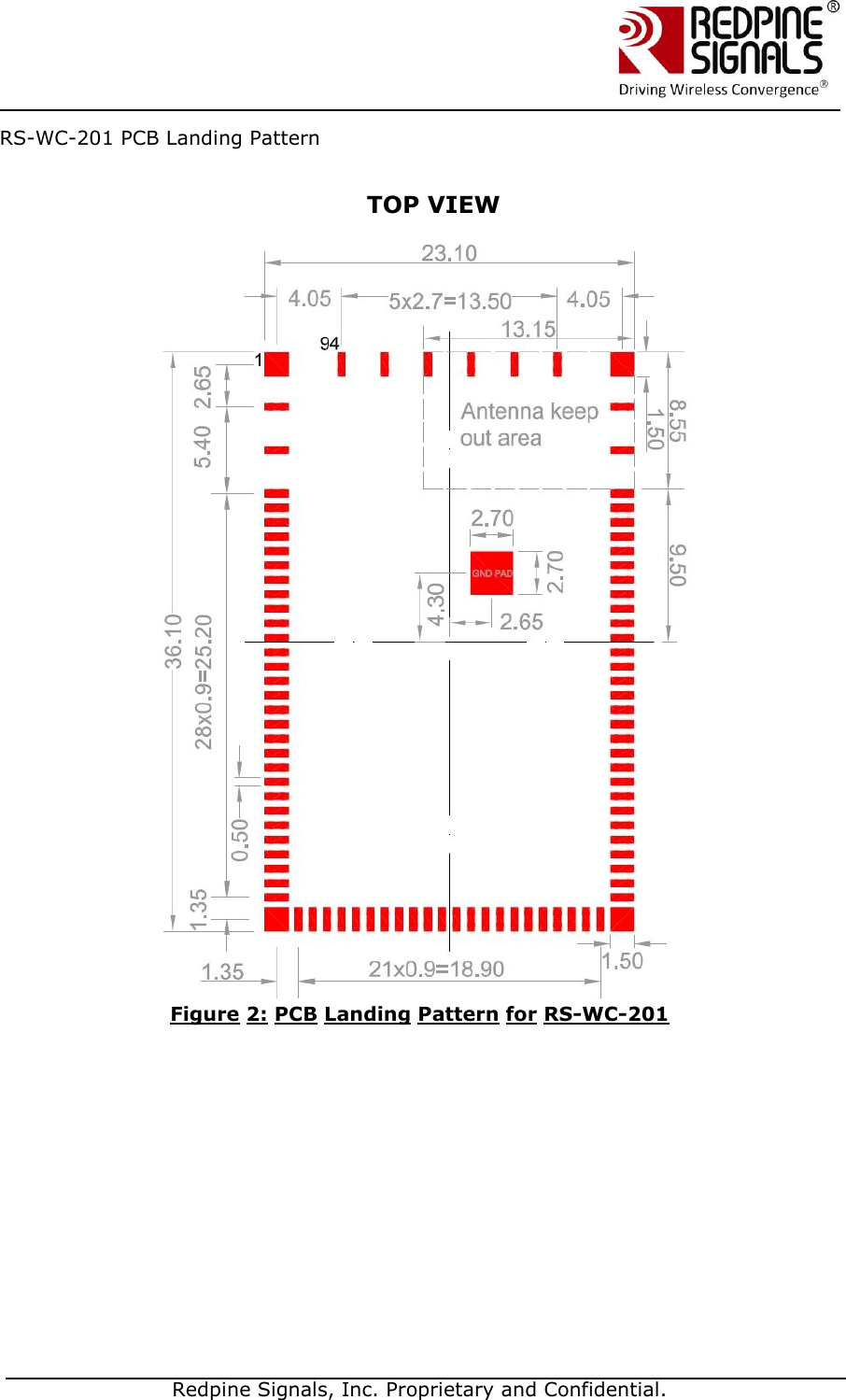
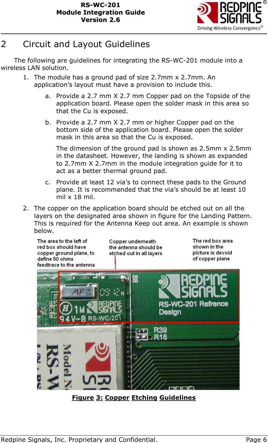
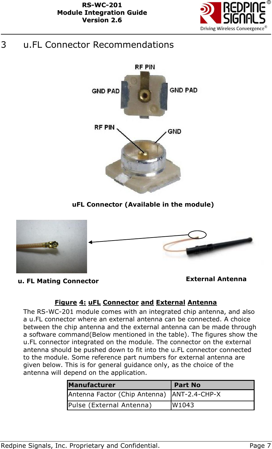
Silicon Labs RSWC201 802.11 bgn WiSeConnect MODULE User Manual Overview

Redpine Signals Inc 802.11 bgn WiSeConnect MODULE Overview

Contents

Manual

  Redpine Signals, Inc. Proprietary and Confidential.              RS-WC-201   MMoodduullee  IInntteeggrraattiioonn  GGuuiiddee    VVeerrssiioonn  22..66    October 2012                             Redpine Signals, Inc. 2107 N. First Street, #680 San Jose, CA 95131. Tel: (408) 748-3385 Fax: (408) 705-2019  Email: info@redpinesignals.com  Website: www.redpinesignals.com
    Redpine Signals, Inc. Proprietary and Confidential.     Page 2 RRSS--WWCC--220011    MMoodduullee  IInntteeggrraattiioonn  GGuuiiddee  VVeerrssiioonn  22..66    Table of Contents RS-WC-201 ............................................................................... 1 1    Reset Timing ................................................................................. 4 2   Circuit and Layout Guidelines ............................................... 6 3   u.FL Connector Recommendations ........................................ 7 4   FCC and IC Declaration ......................................................... 8
    Redpine Signals, Inc. Proprietary and Confidential.     Page 3 RRSS--WWCC--220011    MMoodduullee  IInntteeggrraattiioonn  GGuuiiddee  VVeerrssiioonn  22..66     List of Figures  Figure 1: Reset Timing ................................................................................. 4 Figure 2: PCB Landing Pattern for RS-WC-201 ............................................. 5 Figure 3: Copper Etching Guidelines ............................................................. 6 Figure 4: uFL Connector and External Antenna ............................................ 7
    Redpine Signals, Inc. Proprietary and Confidential.     Page 4 RRSS--WWCC--220011    MMoodduullee  IInntteeggrraattiioonn  GGuuiiddee  VVeerrssiioonn  22..66     1 Reset Timing  Following diagram shows the timing requirement for Reset input in two scenarios.  A. Power up B. Giving reset during module operation    Figure 1: Reset Timing 3.3V input  supply 20msec A 1msec B Reset_n
  Redpine Signals, Inc. Proprietary and Confidential.  RS-WC-201 PCB Landing Pattern               TOP VIEW  Figure 2: PCB Landing Pattern for RS-WC-201
    Redpine Signals, Inc. Proprietary and Confidential.     Page 6 RRSS--WWCC--220011    MMoodduullee  IInntteeggrraattiioonn  GGuuiiddee  VVeerrssiioonn  22..66    2   Circuit and Layout Guidelines The following are guidelines for integrating the RS-WC-201 module into a wireless LAN solution. 1. The module has a ground pad of size 2.7mm x 2.7mm. An application’s layout must have a provision to include this.  a. Provide a 2.7 mm X 2.7 mm Copper pad on the Topside of the application board. Please open the solder mask in this area so that the Cu is exposed. b. Provide a 2.7 mm X 2.7 mm or higher Copper pad on the bottom side of the application board. Please open the solder mask in this area so that the Cu is exposed. The dimension of the ground pad is shown as 2.5mm x 2.5mm in the datasheet. However, the landing is shown as expanded to 2.7mm X 2.7mm in the module integration guide for it to act as a better thermal ground pad.  c. Provide at least 12 via’s to connect these pads to the Ground plane. It is recommended that the via’s should be at least 10 mil x 18 mil. 2. The copper on the application board should be etched out on all the layers on the designated area shown in figure for the Landing Pattern. This is required for the Antenna Keep out area. An example is shown below.  Figure 3: Copper Etching Guidelines
    Redpine Signals, Inc. Proprietary and Confidential.     Page 7 RRSS--WWCC--220011    MMoodduullee  IInntteeggrraattiioonn  GGuuiiddee  VVeerrssiioonn  22..66    3  u.FL Connector Recommendations                                 Figure 4: uFL Connector and External Antenna The RS-WC-201 module comes with an integrated chip antenna, and also a u.FL connector where an external antenna can be connected. A choice between the chip antenna and the external antenna can be made through a software command(Below mentioned in the table). The figures show the u.FL connector integrated on the module. The connector on the external antenna should be pushed down to fit into the u.FL connector connected to the module. Some reference part numbers for external antenna are given below. This is for general guidance only, as the choice of the antenna will depend on the application.  Manufacturer   Part No Antenna Factor (Chip Antenna) ANT-2.4-CHP-X Pulse (External Antenna) W1043  u. FL Mating Connector External Antenna uFL Connector (Available in the module)
    Redpine Signals, Inc. Proprietary and Confidential.     Page 8 RRSS--WWCC--220011    MMoodduullee  IInntteeggrraattiioonn  GGuuiiddee  VVeerrssiioonn  22..66    4   FCC and IC Declaration                This device complies with Part 15 of the FCC Rules. Operation is subject to the following two conditions: (1) This device may not cause harmful interference, and (2) This device must accept any interference received, including interference that may cause undesired operation.                                                                                                  NOTE: This equipment has been tested and found to comply with the limits for a Class B digital device, pursuant to part 15 of the FCC Rules. These limits are designed to provide reasonable protection against harmful interference when the equipment is operated in a commercial environment. This equipment generates, uses, and can radiate radio frequency energy and, if not installed and used in accordance with the instruction manual, may cause harmful interference to radio communications. Operation of this equipment in a residential area is likely to cause harmful interference in which case the user will be required to correct the interference at his own expense.                                                                                                                                                                                                                                                                                                                                                                                                                                                       This Class B digital apparatus complies with Canadian ICES-003.  Cet appareil numérique de la classe A est conforme à la norme NMB-003 du Canada.  This device complies with Industry Canada license-exempt RSS standard(s). Operation is subject to the Following two conditions :( 1) this device may not cause interference, and                                                            (2) This device must accept any interference, including interference that may cause undesired operation of the device.                                                                                                                                     Le présent appareil est conforme aux CNR d'Industrie Canada applicables aux appareils radio exempts de licence. L'exploitation est autorisée aux deux conditions suivantes : (1) l'appareil ne doit pas produire de brouillage, et (2) l'utilisateur de l'appareil doit accepter tout brouillage radioélectrique subi, même si le brouillage est susceptibled'en compromettre le fonctionnement.         CAUTION: Any changes or modifications not expressly approved by the party responsible for compliance could void the user’s authority to operate the equipment.   This equipment should be installed and operated with minimum distance 20 cm between the radiator & your body.                                                                                                                 End Product Labelling This Module is labelled with its own FCC ID. If the FCC ID Certification Number is not visible while installed inside another device, then the device should display the label on it referring the enclosed module. In that case, the final end product must be labelled in a visible area with the following: “Contains Transmitter Module FCC ID: XF6-RSWC201” OR “Contains FCC ID: XF6-RSWC201” The OEM should not provide information to the end user regarding installation or removal of this RF module or change RF related parameters in the user manual of the end product. The OEM integrator is still responsible for testing their end-product for any additional compliance requirements required with this module installed (for example, digital device emissions, PC peripheral requirements, etc.).
    Redpine Signals, Inc. Proprietary and Confidential.     Page 9 RRSS--WWCC--220011    MMoodduullee  IInntteeggrraattiioonn  GGuuiiddee  VVeerrssiioonn  22..66     This Module is labelled with its own IC ID. If the IC ID Certification Number is not visible while installed inside another device, then the device should display the label on it referring the enclosed module. In that case, the final end product must be labelled in a visible area with the following:  “Contains Transmitter Module IC ID: 80407A-RSWC201”  OR  “Contains IC ID: 80407A-RSWC201”  Ce module est étiqueté avec son propre ID IC. Si le numéro de certification IC ID n'est pas visible lorsqu'il est installé à l'intérieur d'un autre appareil, l'appareil doit afficher l'étiquette sur le module de référence ci-joint. Dans ce cas, le produit final doit être étiqueté dans un endroit visible par le texte suivant:  “Contains Transmitter Module IC ID: 80407A-RSWC201”  OR  “Contains IC ID: 80407A-RSWC201”   énoncé de la FCC (états-Unis seulement) Cet équipement a été testé et jugé conforme aux limites de Classe B pour un appareil numérique, en vertu de l’article 15 de la réglementation de la FCC. Ces limites ont été instaurées our fournir une rotection raisonnable contre toute interférence nuisible dans une installation résidentielle. Cet équipement génère, utilise et peut émettre de l’énergie radiofréquence. S’il n’est pas installé et utilisé conformément aux instructions, il peut provoquer des interférences sur les communications radio. Cependant, il n’est pas garanti que des interférences ne se produiront pas dans certaines installations. Si cet équipement cause des interférences à la reception radio ou télévisée (ce qui peut être vérifi é en éteignant l’appareil puis en le remettant sous tension), l’utilisateur peut enter de  ésoudre en suivant une ou plusieurs des mesures ci-après : Réorienter ou déplacer l’antenne réceptrice. ugmenter l’espace entre l’appareil et le récepteur. Brancher l’appareil à une prise de courant différente de celle sur laquelle le récepteur est branché. Pour obtenir de l’aide, contacter le vendeur ou un technician radio/television expérimenté.  REMARQUE: Toute modifi cation non autorisée expressément par le fabricant responsable de la onformité peut annuler le droit de l’utilisateur à faire fonctionner le produit.
    Redpine Signals, Inc. Proprietary and Confidential.     Page 10 RRSS--WWCC--220011    MMoodduullee  IInntteeggrraattiioonn  GGuuiiddee  VVeerrssiioonn  22..66    Document History:  Rev. Ver. No. Date Changes 1.  0.1 10, Feb 2012 Initial version. 2.  1.0 27 Mar, 2012 Merged schematics for UART and SPI 3.  2.0 8 May, 2012 Added antenna keep-out area for the module, put in Rev 2.0 schematics. Added details about pin settings for SPI/UART interface selection 4.  2.1 13 Jul,2012 USB interface added 5.  2.2 17 July, 2012 Added new schematics to match the datasheet version 1.4 6.  2.3 20 July, 2012 Changed peak current to 400mA 7.  2.4 1 Aug, 2012 Removed statement that WAKEUP is not supported 8.  2.5 30 Aug, 2012 USB interface added 9.  2.6 5 Oct, 2012 Connections for pin 13 and 14 are changed. Now they are connected to the MCU for wireless firmware upgrade  Review History Ver. No. Date Reviewer Comments Action 2.0 01 May, 2012 Suresh  Closed version 2.0 after review completion

Navigation menu