Silvus Technologies SC3822 MIMO OFDM Radio User Manual StreamCaster V3 12
Silvus Technologies, Inc. MIMO OFDM Radio StreamCaster V3 12
UserManual.wiki
>
Silvus Technologies
>
SC3822 User Manual
User Manual
Navigation menu
Upload a User Manual
Namespaces
Wiki Guide
HTML
PDF
Info
Views
User Manual
Discussion / Help
Navigation
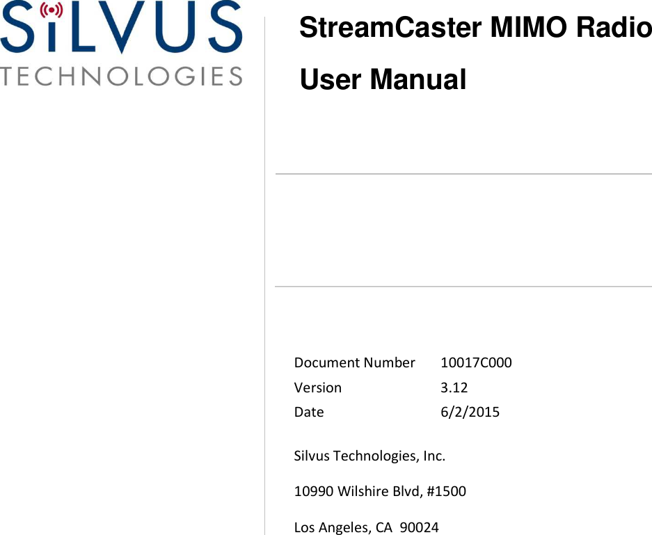


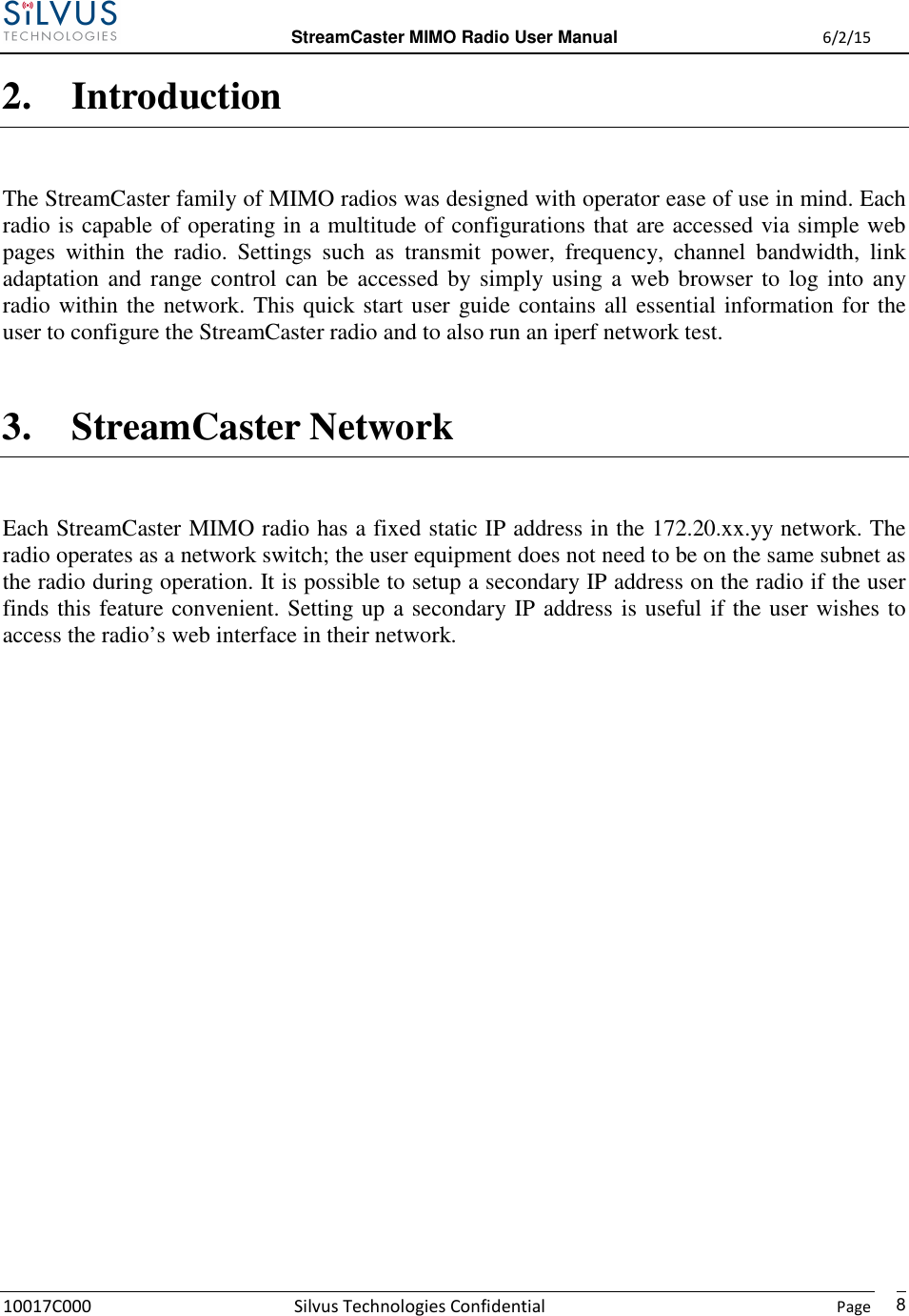
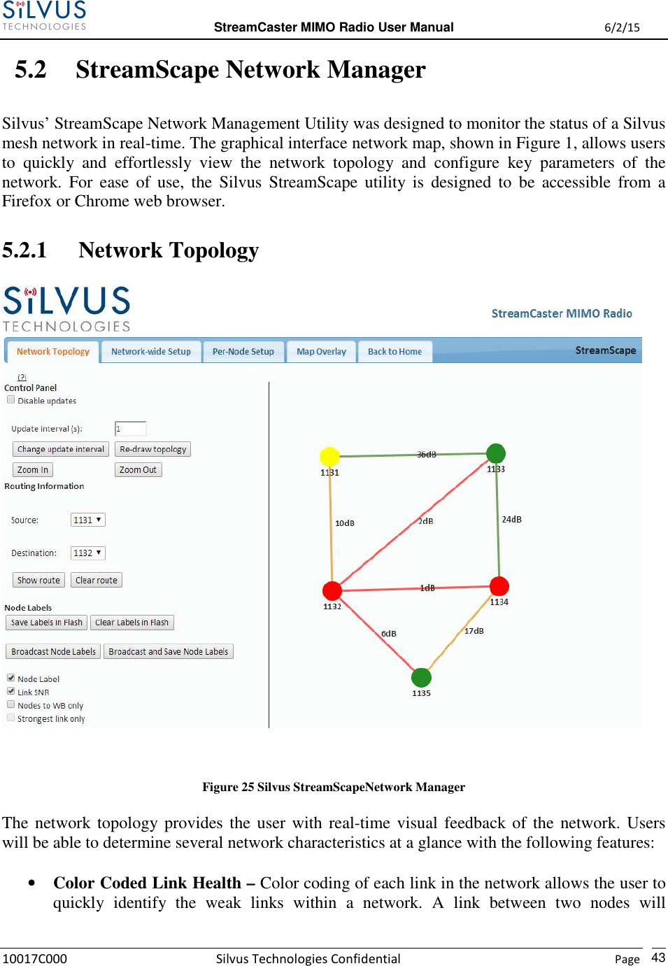
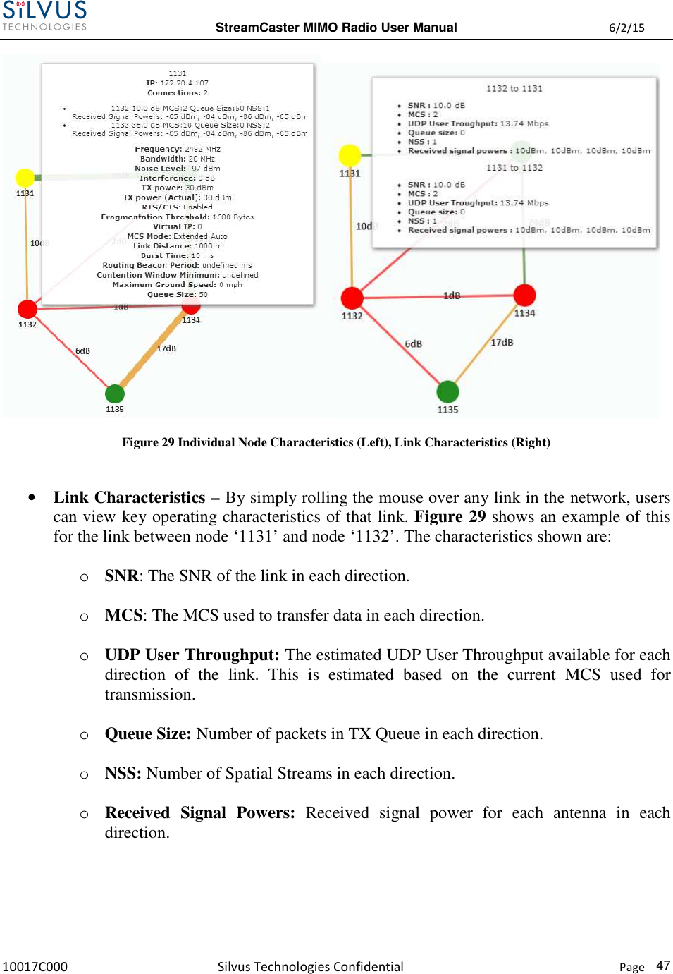
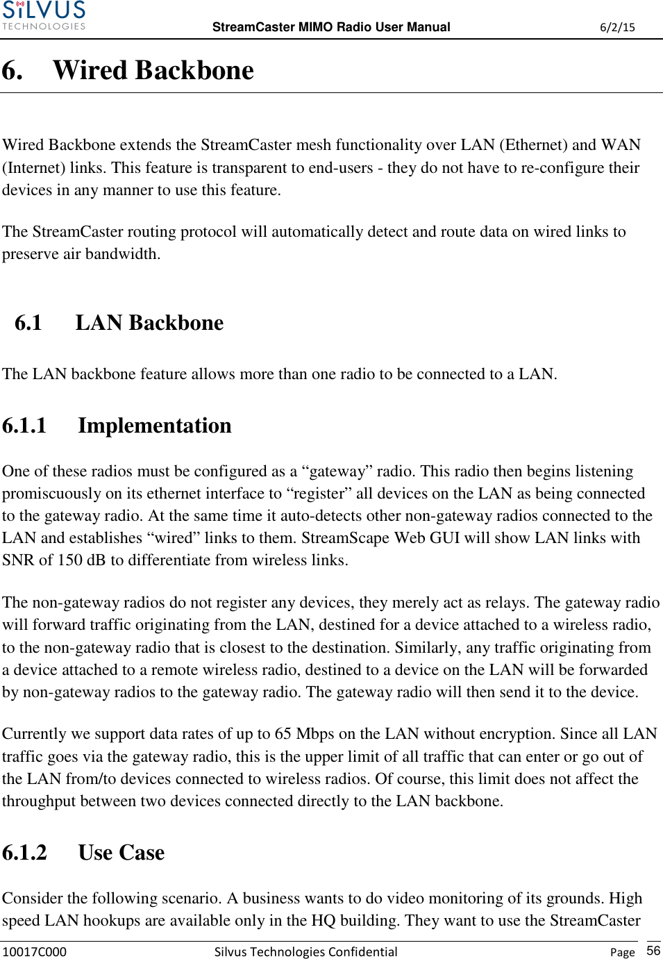
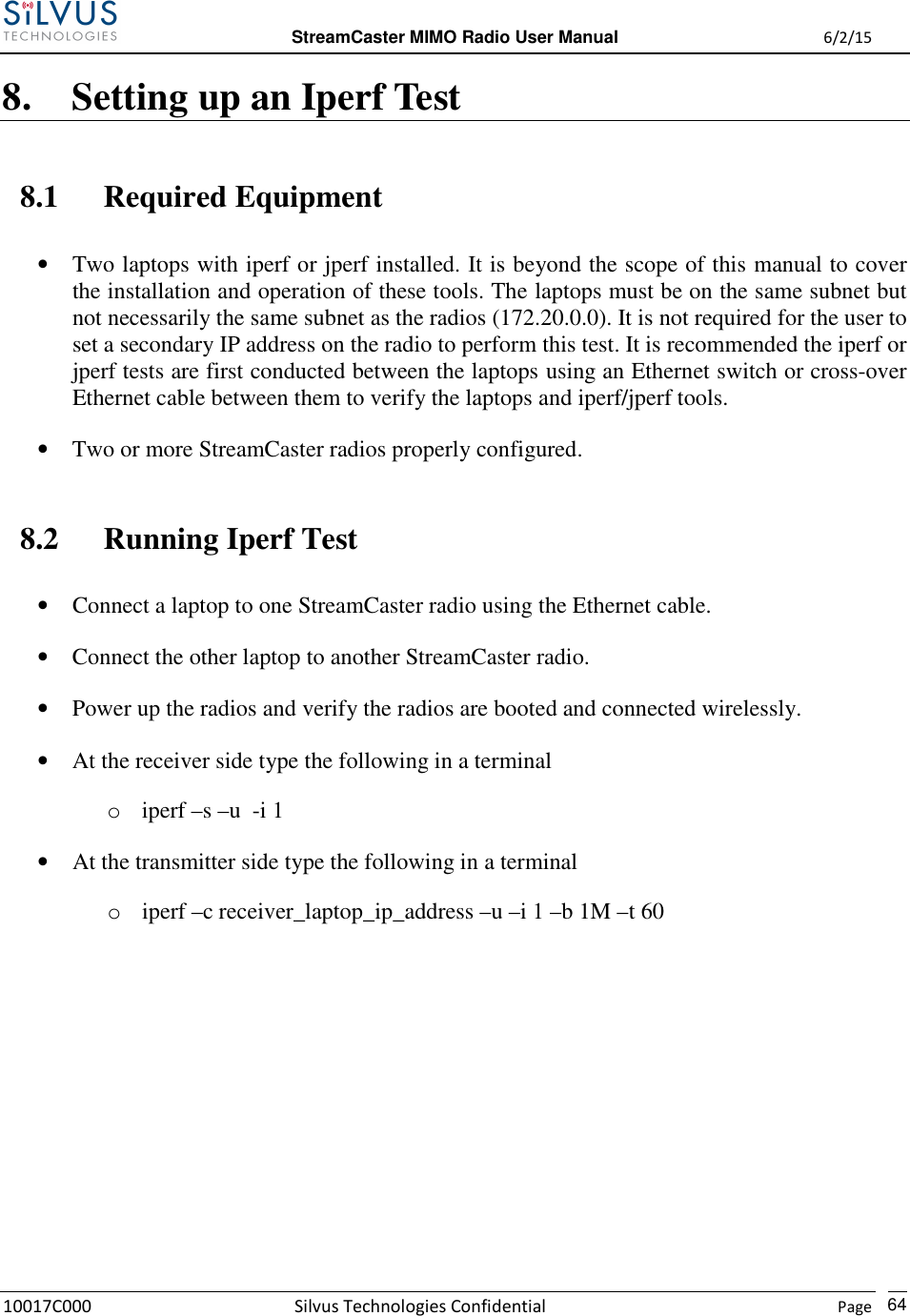
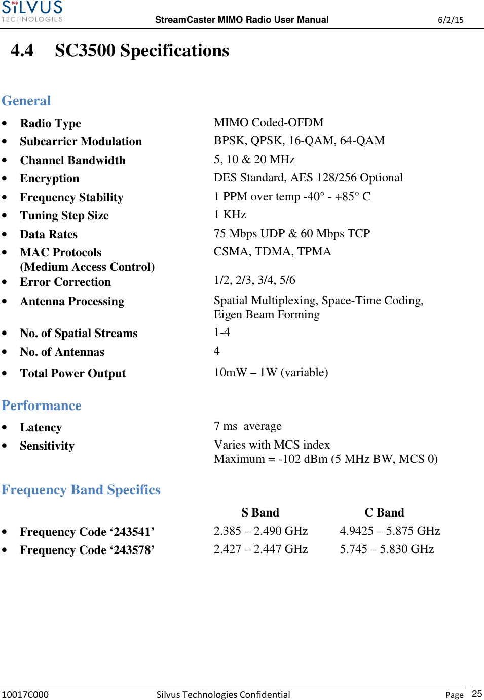
![StreamCaster MIMO Radio User Manual 6/2/15 10017C000 Silvus Technologies Confidential Page 94. Hardware Overview 4.1 StreamCaster Hardware Interface SC3822: Figure 1 StreamCaster 3822 Ruggedized Enclosure RF channels 1-2 connectors [SMA Female] USB/GPIO connector [Hirose LF10WBRB-12SD] Tri-Color Status LED (See Section 10.1 for Troubleshooting Information) • Red – Radio is in the process of booting up • Orange – Radio is fully booted but not wirelessly connected to any other radio • Green – Radio is wirelessly connected to at least one other radio • Flashing Red – Radio has recovered from a bad state and has reverted to factory default settings. Power (9-32 VDC), Ethernet, and Serial Port connector [Hirose LF10WBRB-12PD] 1 2 3 4 2 1 3 4](https://usermanual.wiki/Silvus-Technologies/SC3822/User-Guide-2724356-Page-12.png)
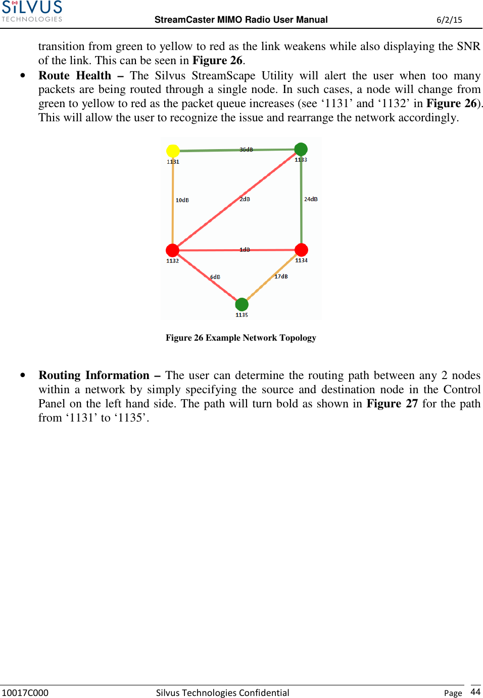
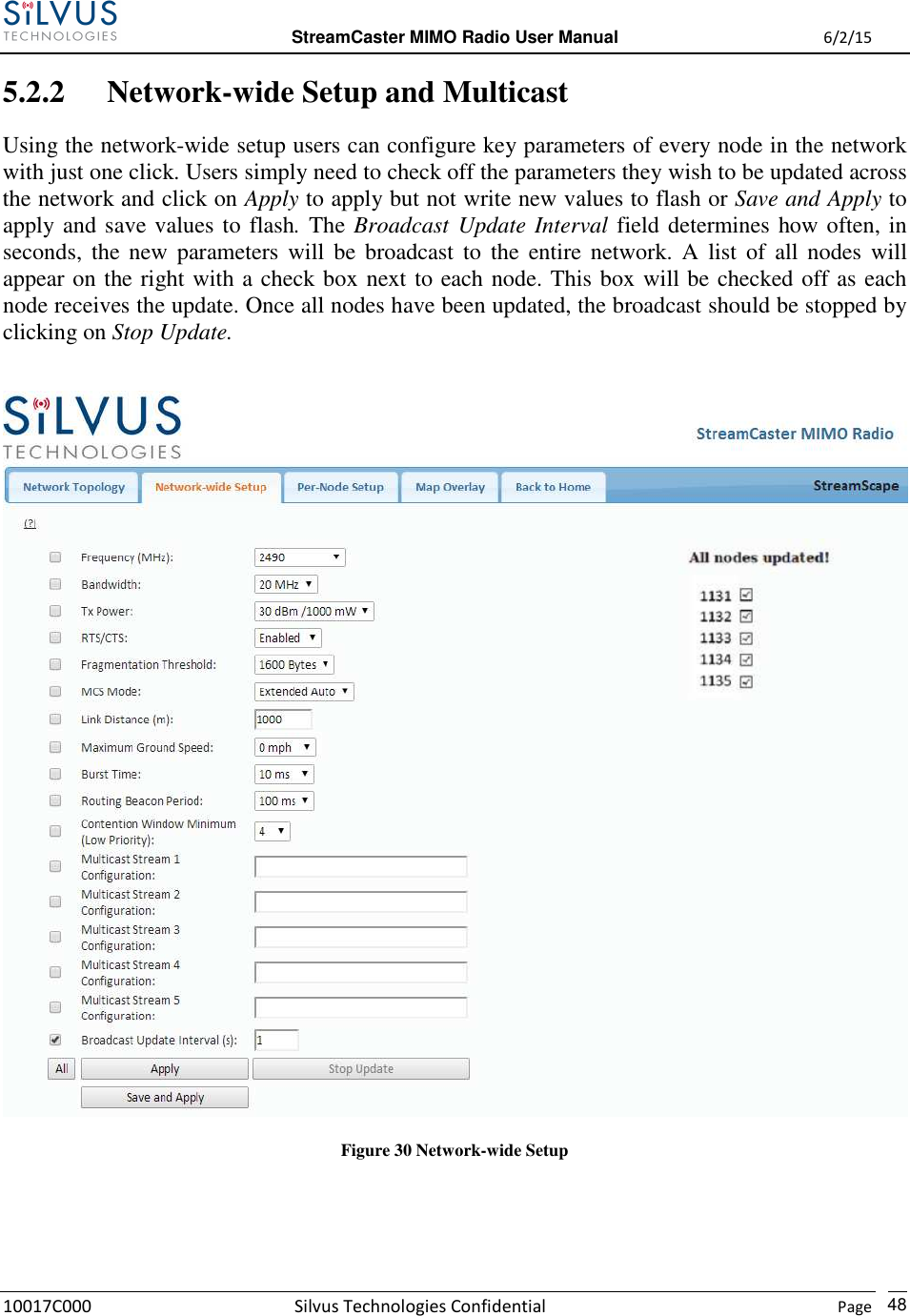
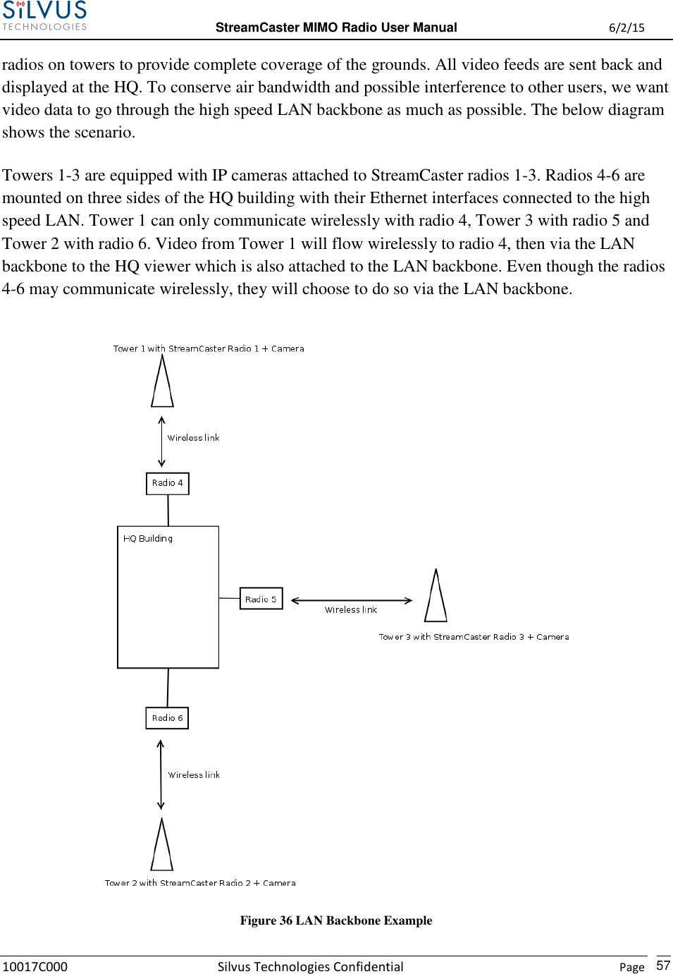
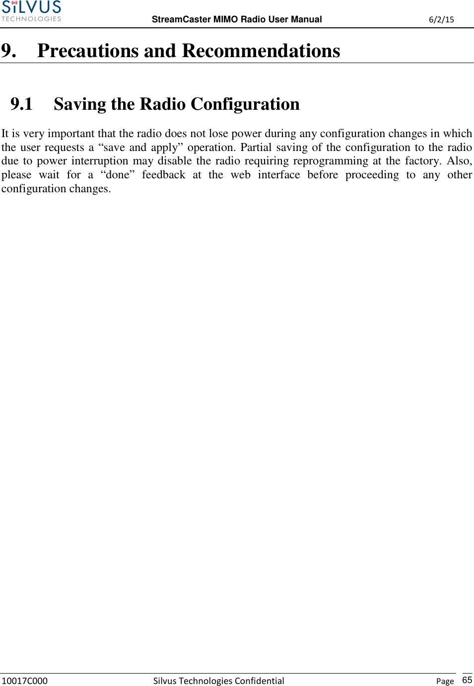
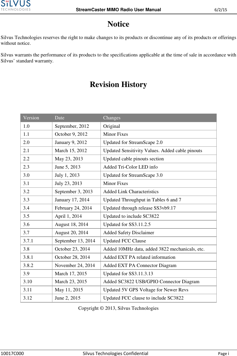
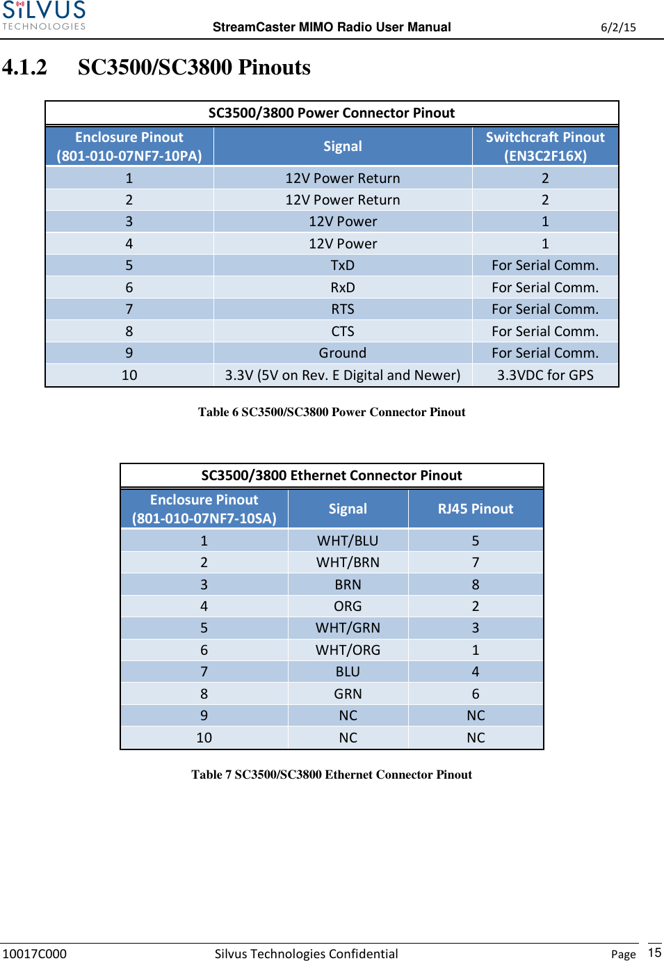
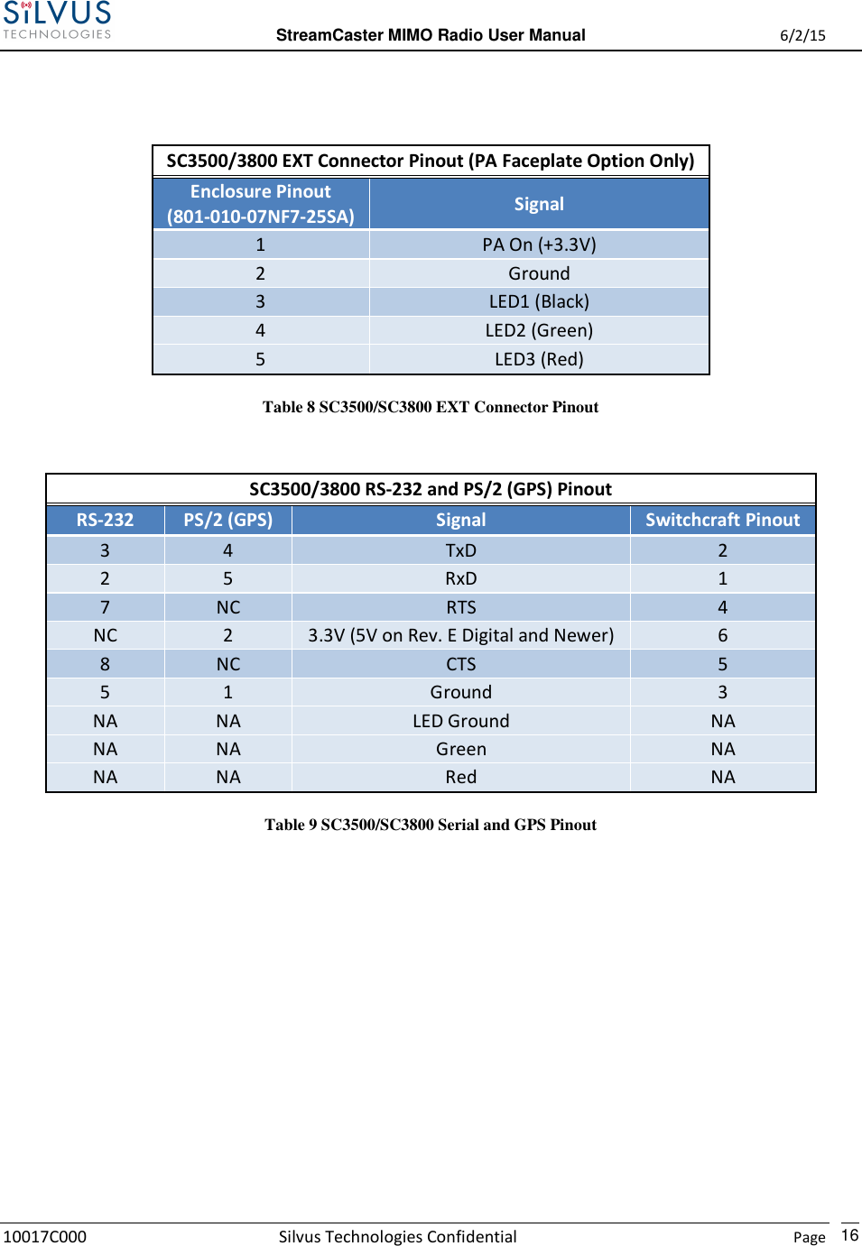
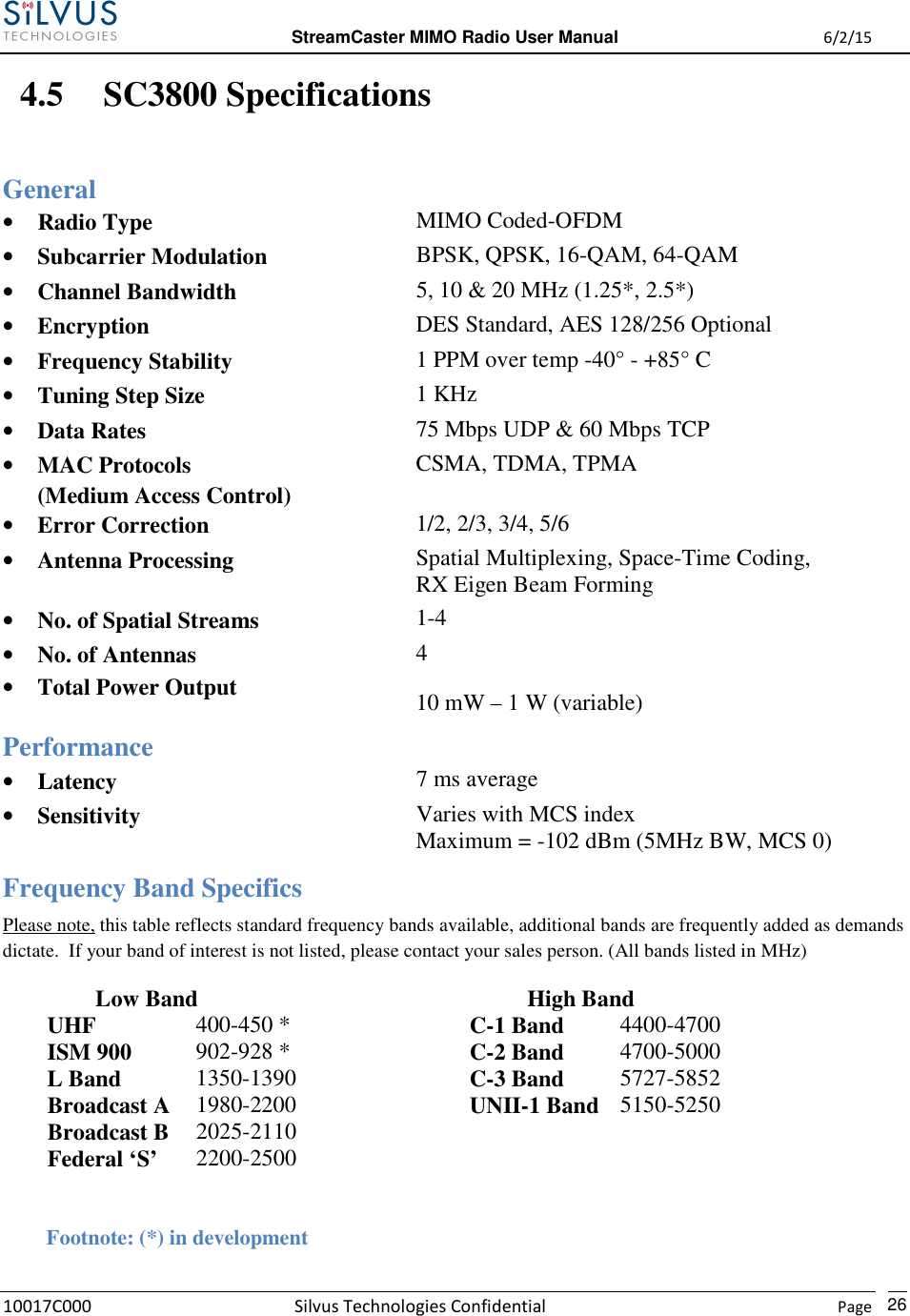
![StreamCaster MIMO Radio User Manual 6/2/15 10017C000 Silvus Technologies Confidential Page 10 SC3500/SC3800: Figure 2 StreamCaster 3500/3800 Ruggedized Enclosure RF channels 1-4 connectors [TNC Female] Ethernet connector [Mighty-Mouse 801-010-07NF7-10SA] Power (9-20 VDC) and Serial Port connector [Mighty-Mouse 801-010-07NF7-10PA] Tri-Color Status LED (See Section 10.1 for Troubleshooting Information) • Red – Radio is in the process of booting up • Orange – Radio is fully booted but not wirelessly connected to any other radio • Green – Radio is wirelessly connected to at least one other radio • Flashing Red – Radio has recovered from a bad state and has reverted to factory default settings Power Switch 1 2 3 4 5 2 3 4 5 1](https://usermanual.wiki/Silvus-Technologies/SC3822/User-Guide-2724356-Page-13.png)
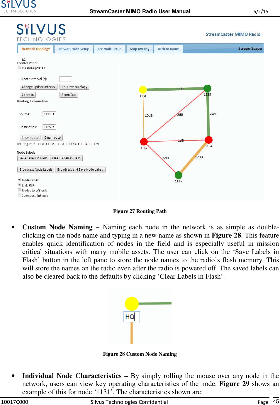
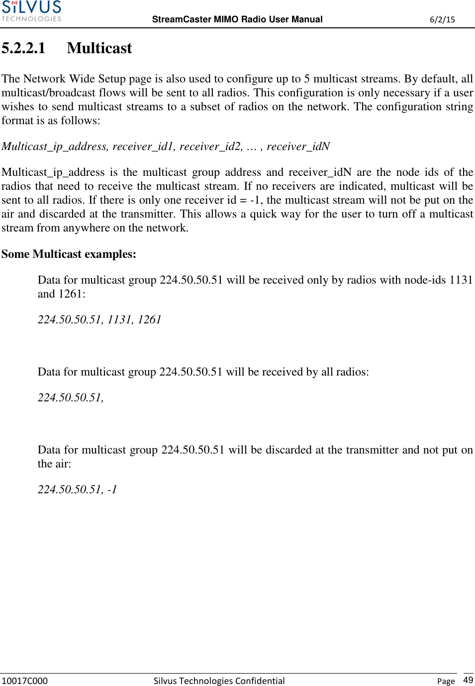
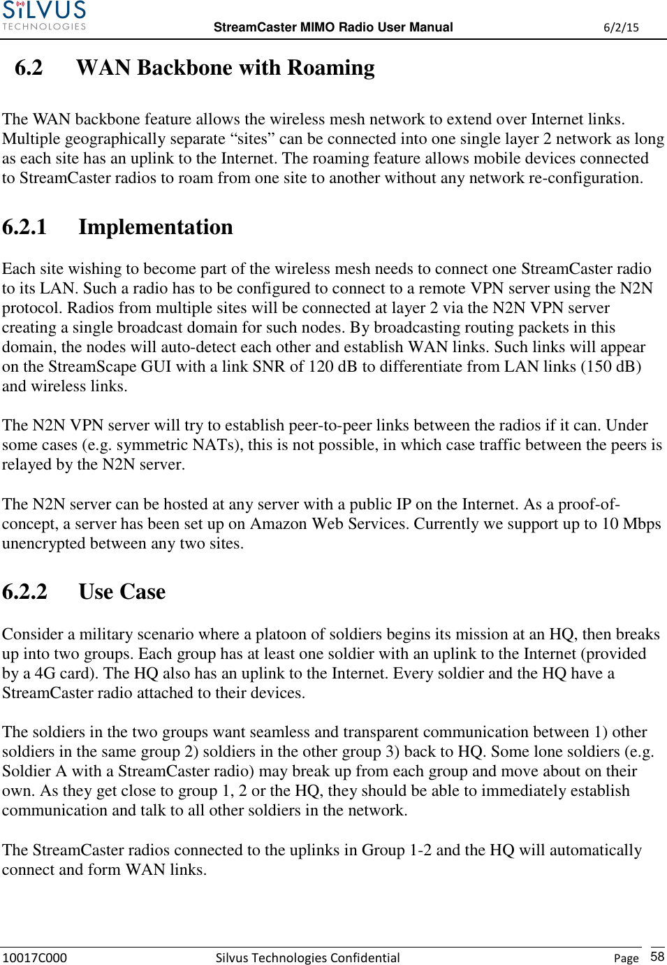
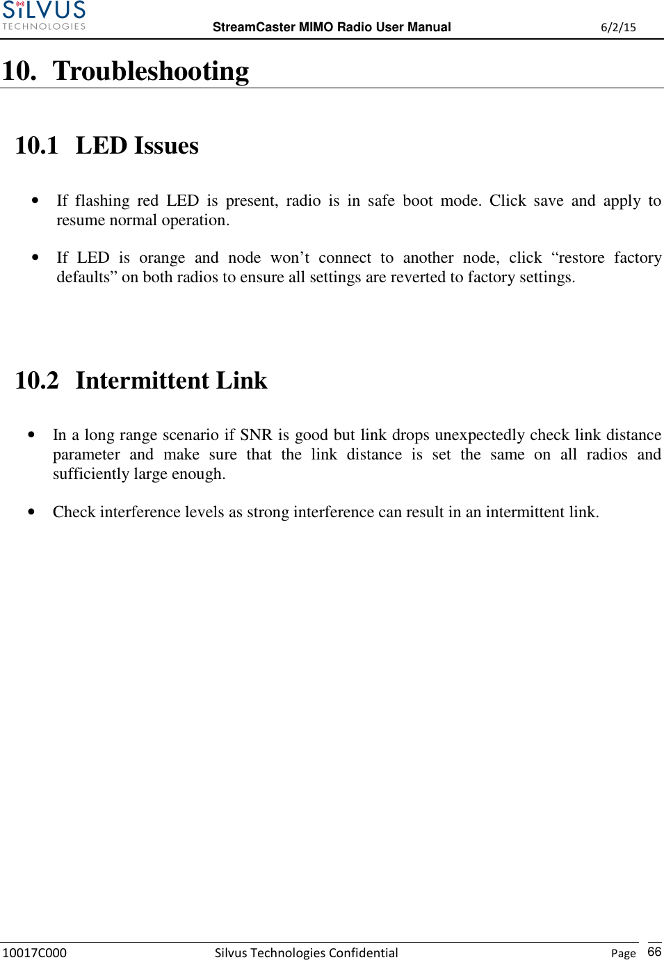
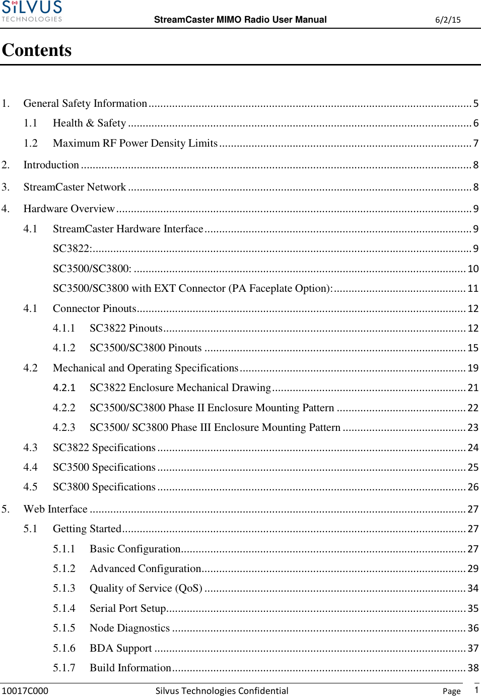
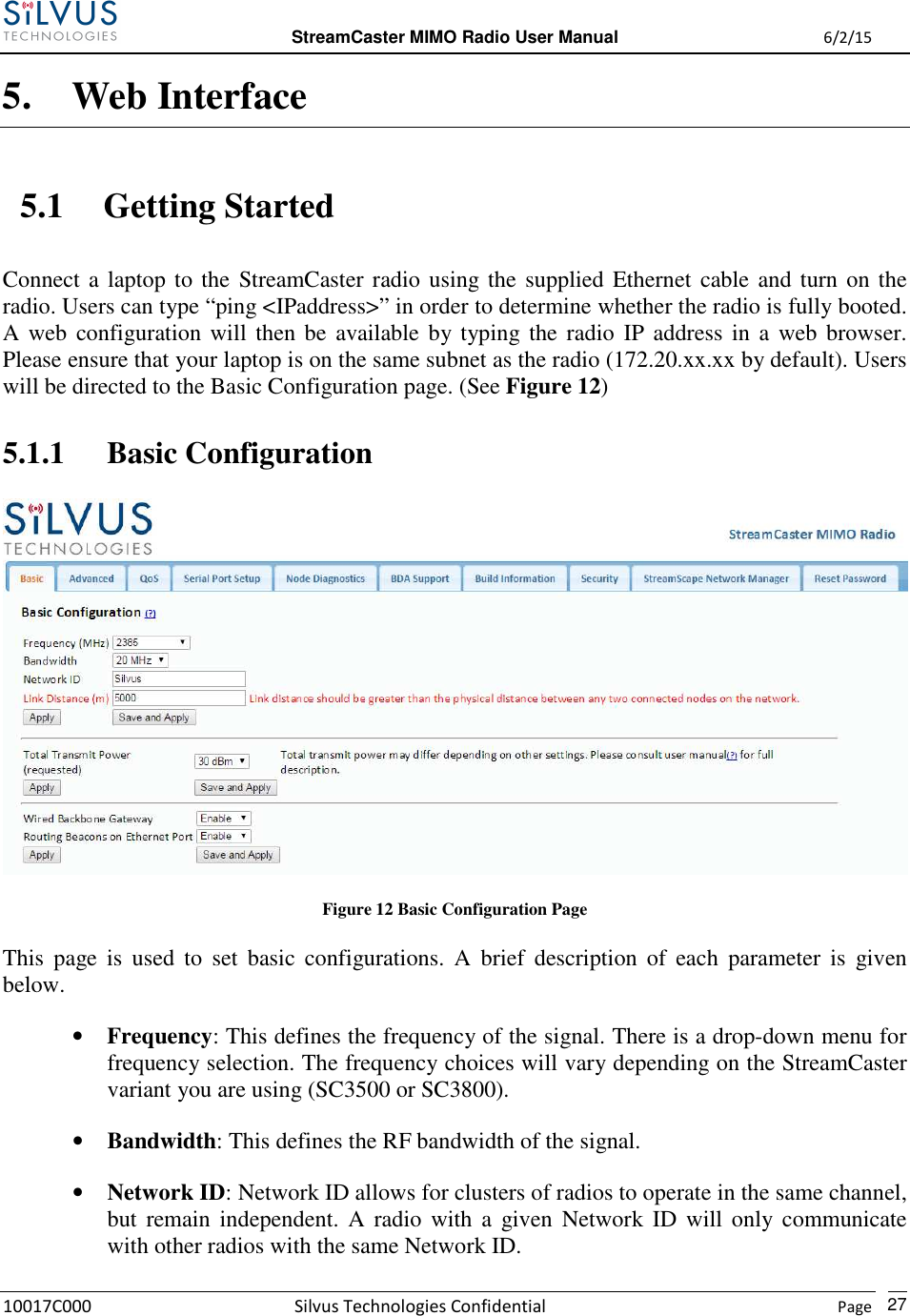
![StreamCaster MIMO Radio User Manual 6/2/15 10017C000 Silvus Technologies Confidential Page 11 SC3500/SC3800 with EXT Connector (PA Faceplate Option): Figure 3 StreamCaster 3500/3800 Ruggedized Enclosure RF channels 1-4 connectors [TNC Female] EXT PA Connector [Mighty-Mouse 801-010-07NF7-25SA] Ethernet connector [Mighty-Mouse 801-010-07NF7-10SA] Power (9-20 VDC) and Serial Port connector [Mighty-Mouse 801-010-07NF7-10PA] Power Switch Tri-Color Status LED (See Section 10.1 for Troubleshooting Information) • Red – Radio is in the process of booting up • Orange – Radio is fully booted but not wirelessly connected to any other radio • Green – Radio is wirelessly connected to at least one other radio • Flashing Red – Radio has recovered from a bad state and has reverted to factory default settings 1 2 3 4 5 6 2 3 4 1 6 5](https://usermanual.wiki/Silvus-Technologies/SC3822/User-Guide-2724356-Page-14.png)


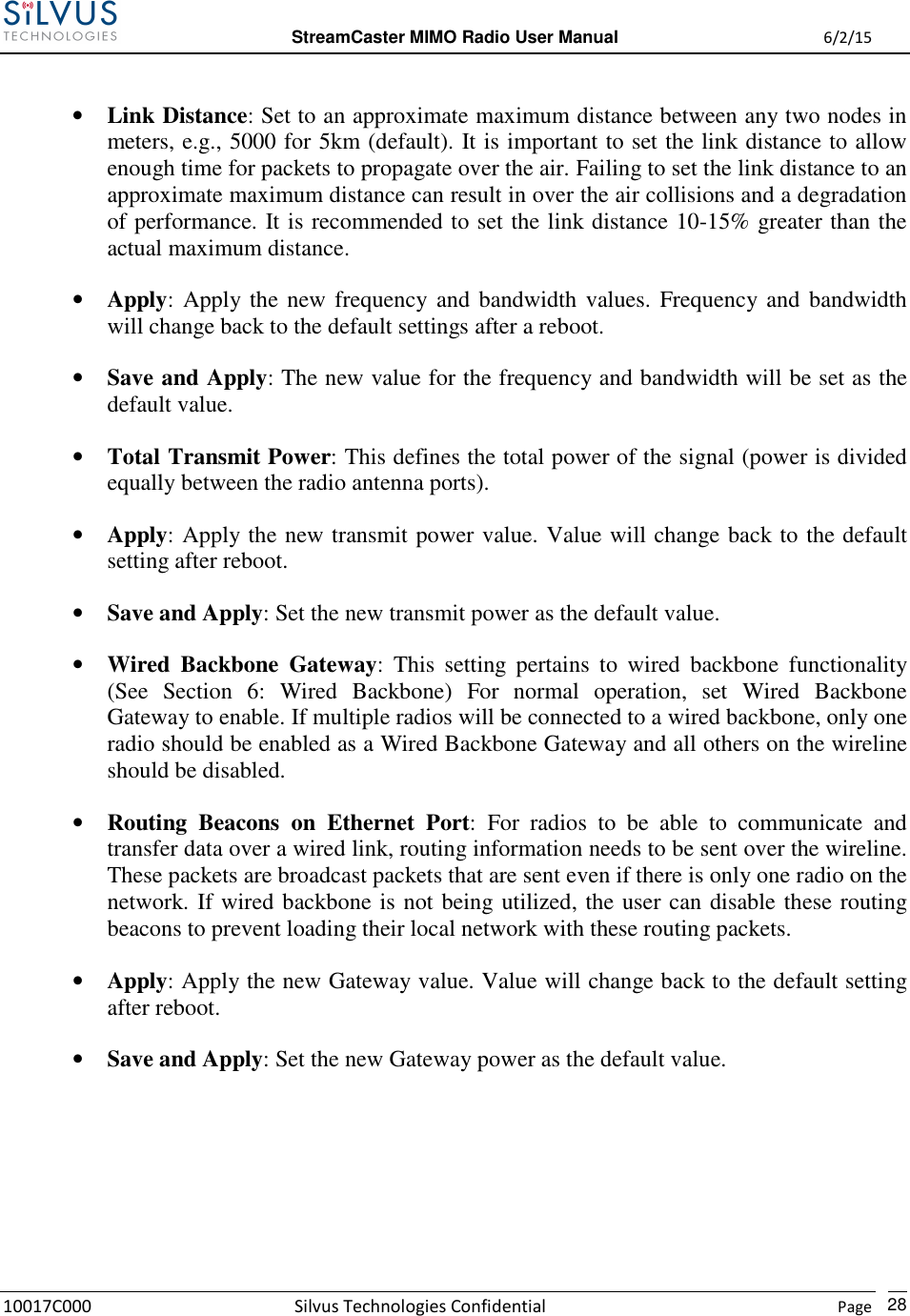
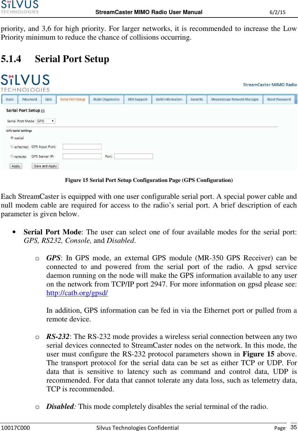
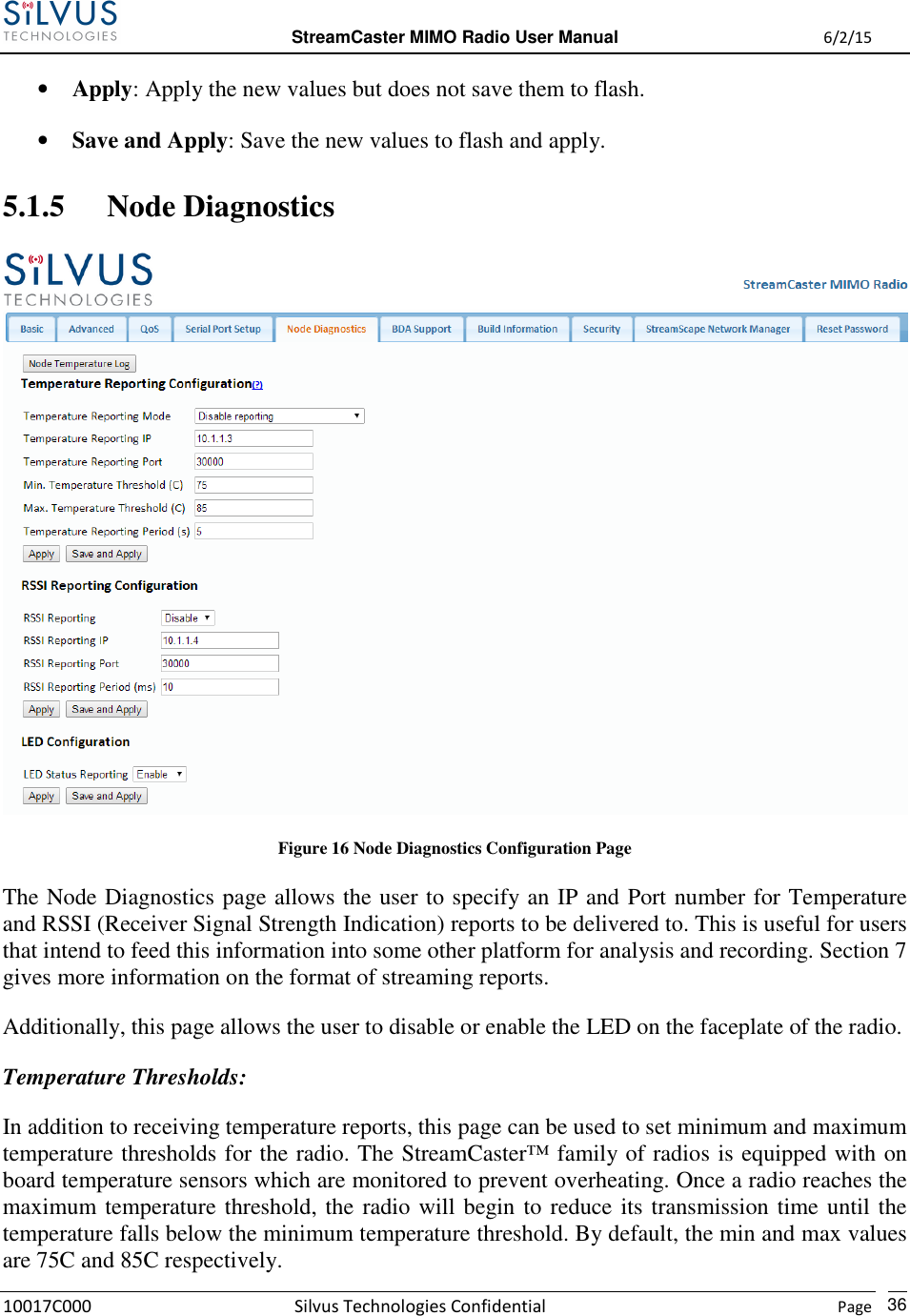
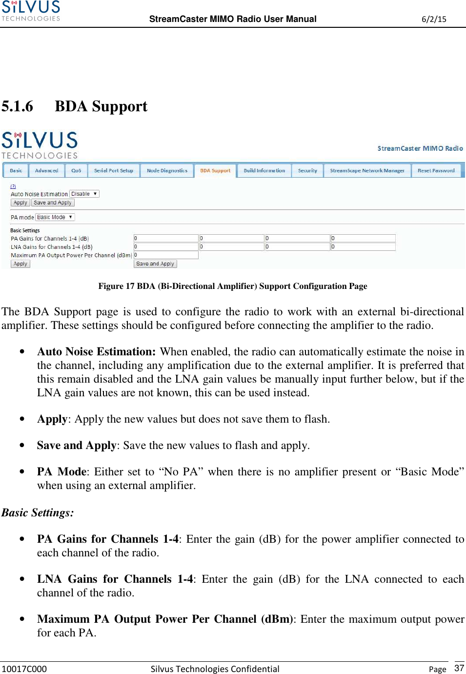
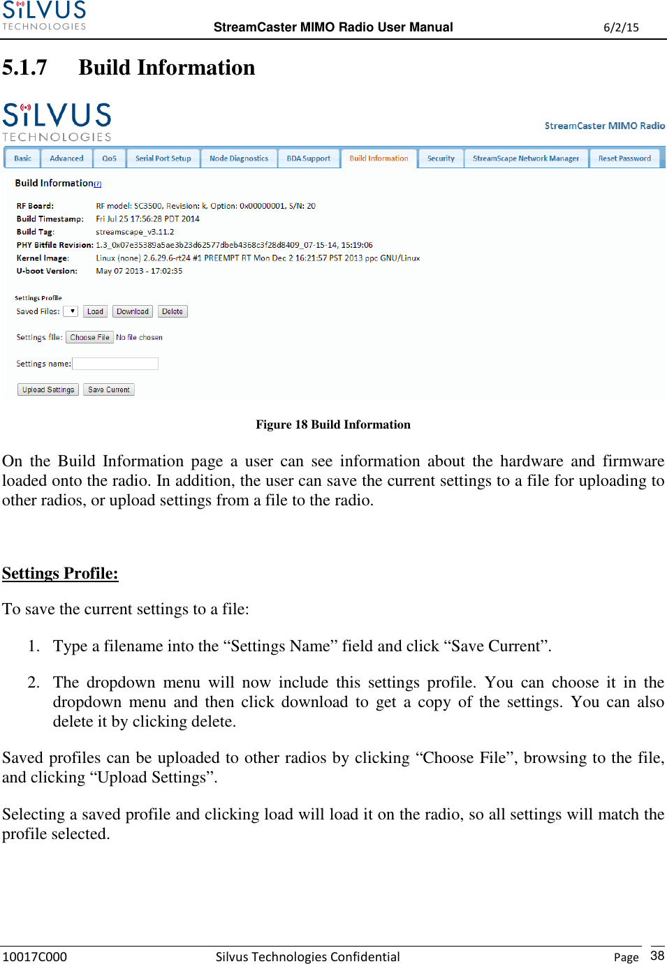
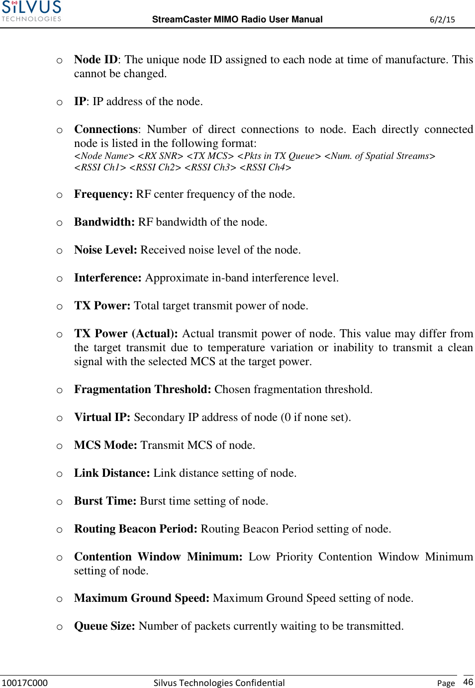
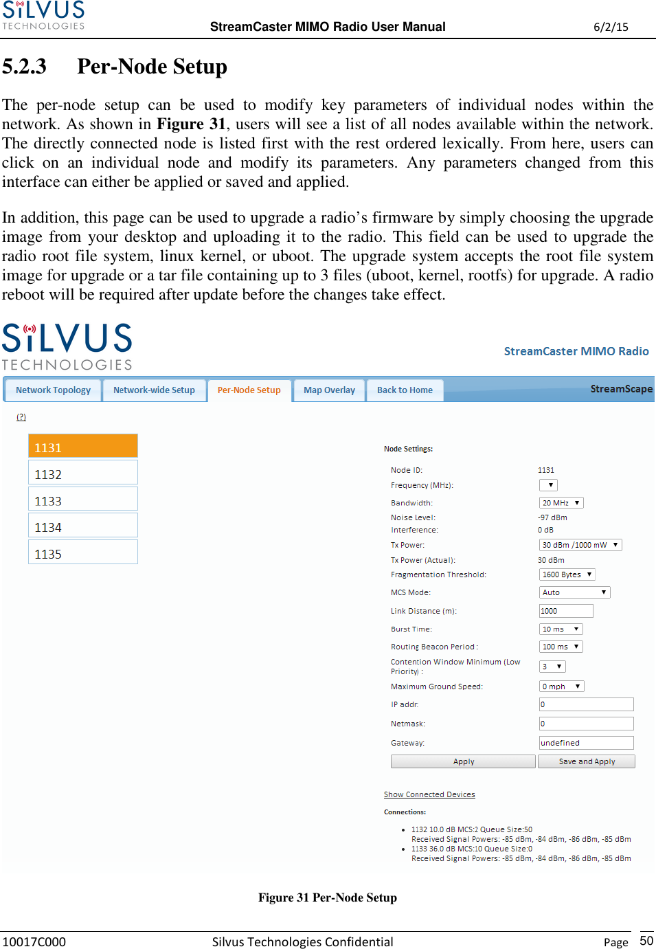
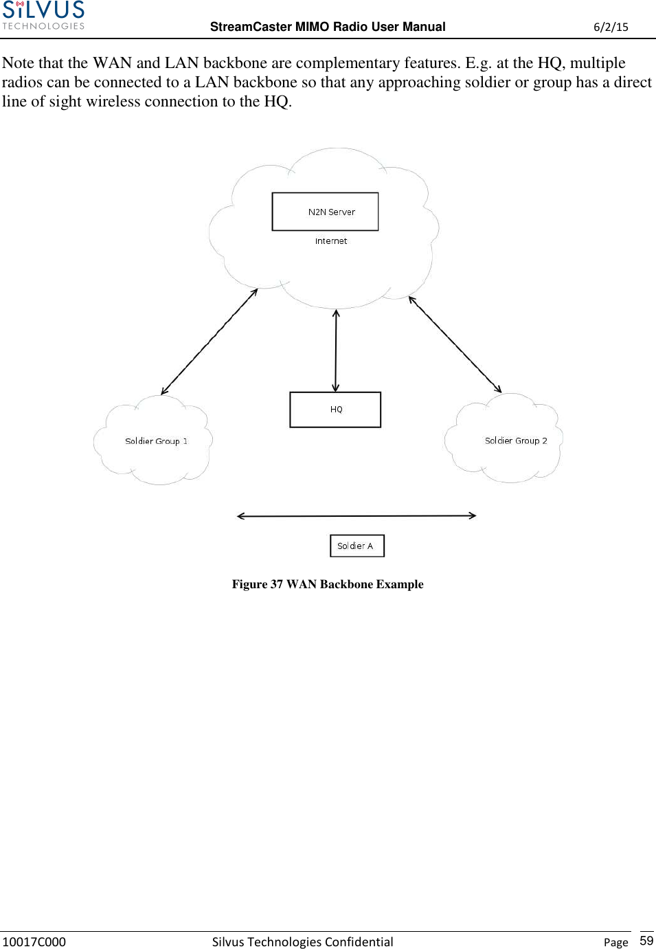
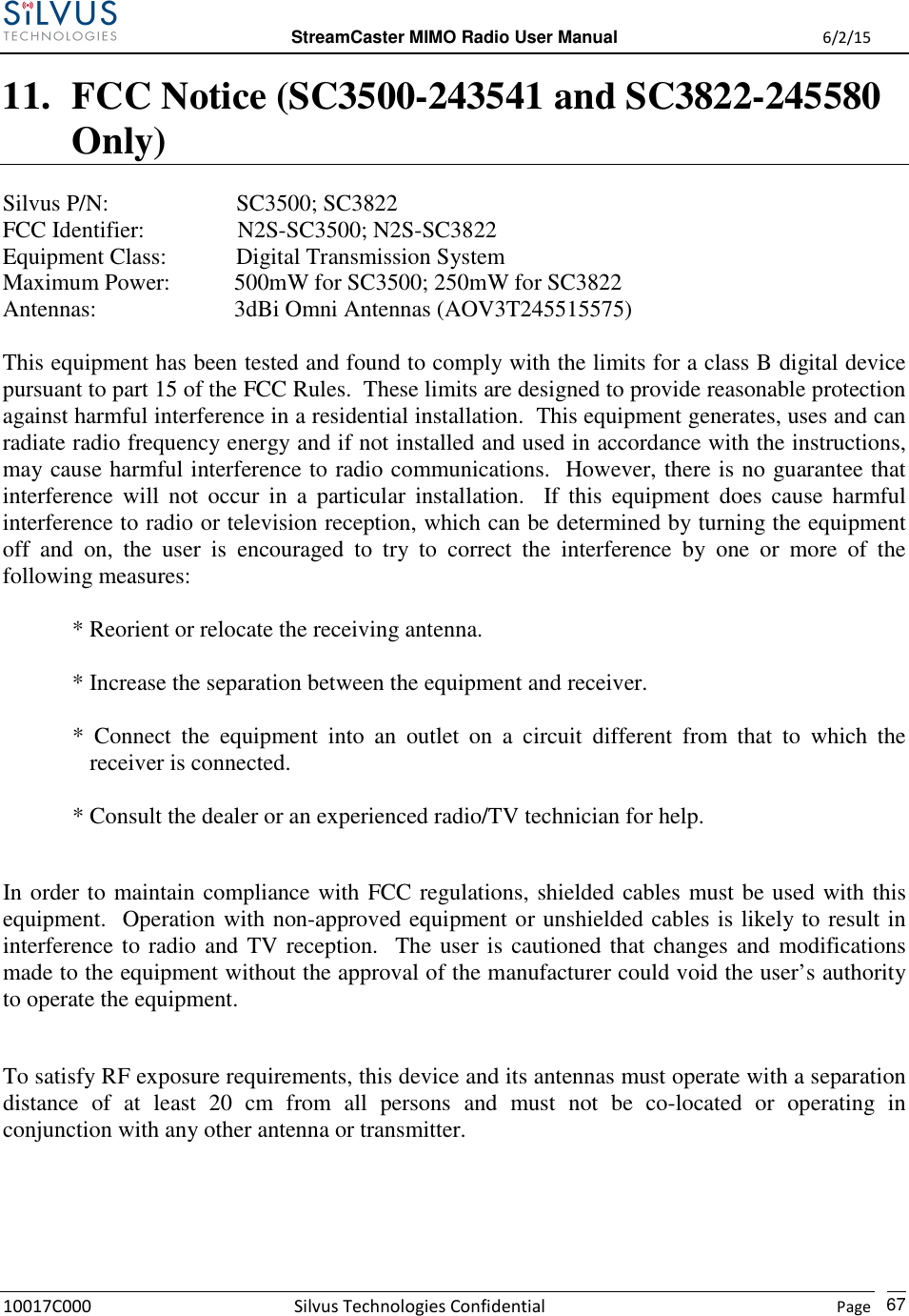
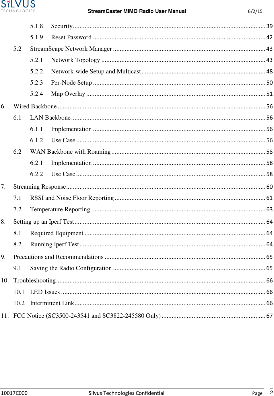
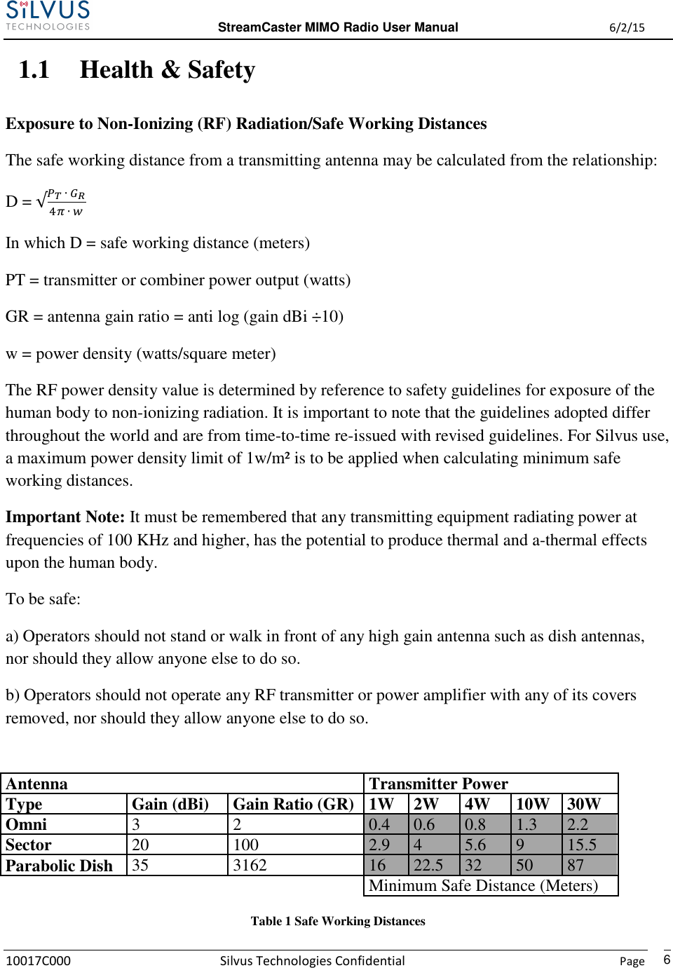
![StreamCaster MIMO Radio User Manual 6/2/15 10017C000 Silvus Technologies Confidential Page 34 5.1.3 Quality of Service (QoS) Figure 14 Quality of Service (QoS) Configuration Page Quality of Service Port Classification: The Quality of Service configuration page allows the user to make a distinction between low and high priority traffic transmitted through each radio. High priority traffic will always jump to the front of the queue and bypass any awaiting low priority traffic. In instances where the link cannot support the amount of data trying to be transmitted, low priority traffic may be completely shelved in order to ensure that the high priority traffic gets through. To specify Low/High priority traffic, the user needs to simply input the port number that the traffic will be arriving on. Multiple ports of the same priority can be separated by a comma (i.e. 5001, 6001, 6002). Alternatively, the user can specify a range of ports using a dash (i.e. 5001-5006). Any combination of commas and dashes will work as well (i.e. 5001, 6001-6007, 8000). Any field can be cleared by removing the text and clicking ‘Apply’ or ‘Save and Apply’. If unspecified, traffic is treated as Low Priority. Quality of Service Contention Window Control: The Quality of Service Contention Window Control tunes the aggressiveness of CSMA backoffs when collisions occur. The MAC takes random backoffs in the range [0, 2^cw_min]. Every time there is a collision/noise it will increase this cw_min by 1, until it is capped by cw_max. E.g. 4,10 translates to random backoffs in the range [0,16] in the beginning for a packet. If the first try results in a collision, it will pick another backoff in the range [0,32], then [0,64], until [0,1024]. After successful transmission, backoff is reset to [0,16]. The default is 4,10 for low](https://usermanual.wiki/Silvus-Technologies/SC3822/User-Guide-2724356-Page-37.png)