Silvus Technologies SC42-520 SC4240 MIMO Radio User Manual
Silvus Technologies, Inc. SC4240 MIMO Radio
User Manual

Document Number
10017C000
Version
3.15.0.4
Date
10/23/2018
Silvus Technologies, Inc.
10990 Wilshire Blvd, #1500
Los Angeles, CA 90024
StreamCaster MIMO Radio
User Manual

StreamCaster MIMO Radio User Manual 7/24/18
10017C000 Sensitive Company Material – Do Not Duplicate Page i
Notice
Silvus Technologies reserves the right to make changes to its products or discontinue any of its products or offerings
without notice.
Silvus Technologies warrants the performance of its products to the specifications applicable at the time of sale in
accordance with Silvus Technologies’ standard warranty.
Revision History
Version
Date
Changes
1.0
September, 2012
Original
1.1
October 9, 2012
Minor Fixes
2.0
January 9, 2012
Updated for StreamScape 2.0
2.1
March 15, 2012
Updated Sensitivity Values. Added cable pinouts
2.2
May 23, 2013
Updated cable pinouts section
2.3
June 5, 2013
Added Tri-Color LED info
3.0
July 1, 2013
Updated for StreamScape 3.0
3.1
July 23, 2013
Minor Fixes
3.2
September 3, 2013
Added Link Characteristics
3.3
January 17, 2014
Updated Throughput in Tables 6 and 7
3.4
February 24, 2014
Updated through release SS3vb9.17
3.5
April 1, 2014
Updated to include SC3822
3.6
August 18, 2014
Updated for SS3.11.2.5
3.7
August 20, 2014
Added Safety Disclaimer
3.7.1
September 13, 2014
Updated FCC Clause
3.8
October 23, 2014
Added 10MHz data, added 3822 mechanicals, etc.
3.8.1
October 28, 2014
Added EXT PA related information
3.8.2
November 24, 2014
Added EXT PA Connector Diagram
3.9
March 17, 2015
Updated for SS3.11.3.13
3.10
March 23, 2015
Added SC3822 USB/GPIO Connector Diagram
3.11
May 11, 2015
Updated 5V GPS Voltage for Newer Revs
3.11.1
June 2, 2015
Updated FCC clause to include SC3822
3.12
September 10, 2015
Updated for SS3.12 – Added VLAN, USB, and
Spectrum Scan support
3.12.1
February 17, 2016
Corrected 3822 Voltage Range in Table 5
3.12.2
April 28, 2016
Added SC4200
3.12.3
August 18, 2016
Added SC4210 to Section 11 FCC Notes
3.12.4
September 15, 2016
Added Custom Frequency Plan instructions
3.12.5
October 7, 2016
Updated Section 12 FCC Notice

StreamCaster MIMO Radio User Manual 7/24/18
10017C000 Sensitive Company Material – Do Not Duplicate Page ii
Copyright © 2016, Silvus Technologies
3.12.6
December 1, 2016
Updated 3822/4200 Pinout
3.12.6.4
May 22, 2017
Updated for release 3.12.6.4; Added SC4400
3.12.6.5
May 24, 2017
Added Encryption Profile Descriptions
3.12.6.10
August 1, 2017
Added CE info; Added Network Wide Upgrade; Added
iPerf description
3.12.6.11
August 24, 2017
Additional CE Updates on Last 2 pages
3.12.6.12
August 30, 2017
More CE Updates
3.12.6.13
October 19, 2017
Final CE Update; Updated SC4200 Mechanical
Drawing
3.12.6.14
December 11, 2017
Added disclaimer to Section 5.1.2 Advanced
Configuration
3.13.0
March 28, 2018
Updated SC4200 Photo for ODU PTT
3.13.1
May 14, 2018
Added FCC Info for SC4410-235 and SC4480-235
3.15.0.0
May 15, 2018
Added FIPS features
3.15.0.1
July 2, 2018
Added QoS Scheduler feature
3.15.0.2
July 24, 2018
Reformatted FCC Notice section
3.15.0.3
August 15, 2018
Revised Advanced Configurations to match new
firmware version.
3.15.0.4
October 23, 2018
Added section 13.5 and 13.6

StreamCaster MIMO Radio User Manual 7/24/18
10017C000 Sensitive Company Material – Do Not Duplicate Page
1
Contents
1. General Safety Information ................................................................................................................... 8
1.1 Health & Safety ........................................................................................................................... 8
1.2 Maximum RF Power Density Limits .......................................................................................... 11
2. Introduction ........................................................................................................................................ 12
3. StreamCaster Network ........................................................................................................................ 12
4. StreamCaster Hardware Overview...................................................................................................... 13
4.1 Hardware Interfaces ................................................................................................................. 13
SC4400: ..................................................................................................................................... 13
SC4200: ..................................................................................................................................... 15
SC3822: ..................................................................................................................................... 16
SC3500/SC3800: ....................................................................................................................... 17
SC3500/SC3800 with EXT Connector (PA Faceplate Option): .................................................. 18
4.2 Connector Pinouts .................................................................................................................... 19
4.2.1 SC4400 Pinouts ............................................................................................................ 19
4.2.2 SC4200 Pinouts ............................................................................................................ 23
4.2.3 SC3822 Pinouts ............................................................................................................ 27
4.2.4 SC3500/SC3800 Pinouts .............................................................................................. 30
4.3 Mechanical and Operating Specifications ................................................................................ 35
4.3.1 SC4400 Enclosure Mechanical Drawing....................................................................... 39
4.3.2 SC4200 Enclosure Mechanical Drawing....................................................................... 40
4.3.3 SC3822 Enclosure Mechanical Drawing....................................................................... 41
4.3.4 SC3500/SC3800 Phase II Enclosure Mounting Pattern ................................................ 42
4.3.5 SC3500/ SC3800 Phase III Enclosure Mounting Pattern .............................................. 43
4.4 SC4400 Specifications ............................................................................................................... 44
4.5 SC4200 Specifications ............................................................................................................... 45
4.6 SC3822 Specifications ............................................................................................................... 47
4.7 SC3500 Specifications ............................................................................................................... 48
4.8 SC3800 Specifications ............................................................................................................... 49
5. Web Interface ..................................................................................................................................... 50
5.1 Getting Started ......................................................................................................................... 50
5.1.1 Basic Configuration ...................................................................................................... 51

StreamCaster MIMO Radio User Manual 7/24/18
10017C000 Sensitive Company Material – Do Not Duplicate Page
2
5.1.2 Advanced Configuration .............................................................................................. 53
5.1.3 LAN/WIFI Configuration ............................................................................................... 58
5.1.4 Multicast ...................................................................................................................... 62
5.1.5 Quality of Service (QoS) #QoS ..................................................................................... 63
5.1.6 Serial/USB Setup .......................................................................................................... 67
5.1.7 Node Diagnostics ......................................................................................................... 69
5.1.8 BDA Support ................................................................................................................ 71
5.1.9 Build Information ......................................................................................................... 72
5.1.10 Security…… ................................................................................................................... 73
5.1.11 PTT (SC4400/SC4200 Only) .......................................................................................... 80
5.1.12 Spectrum Scan ............................................................................................................. 82
5.1.13 MPS (Multi-Position Switch) ........................................................................................ 86
5.1.14 Admin Settings ............................................................................................................. 87
5.2 StreamScape Network Manager ............................................................................................... 89
5.2.1 Network Topology ....................................................................................................... 89
5.2.2 Table View ................................................................................................................... 98
5.2.3 Network-wide Setup .................................................................................................. 100
5.2.4 Per-Node Setup ......................................................................................................... 101
5.2.5 Map Overlay .............................................................................................................. 102
6. FIPS Mode ......................................................................................................................................... 108
6.1 Enable FIPS Mode ................................................................................................................... 108
6.1.1 Potential User Errors ................................................................................................. 108
6.2 List of Security Parameters ..................................................................................................... 109
7. Wired Backbone ................................................................................................................................ 110
7.1 LAN Backbone ......................................................................................................................... 110
7.1.1 Implementation ......................................................................................................... 110
7.1.2 Use Case ..................................................................................................................... 110
7.2 WAN Backbone with Roaming ................................................................................................ 111
7.2.1 Implementation ......................................................................................................... 112
7.2.2 Use Case ..................................................................................................................... 112
8. Custom Frequency Plan .................................................................................................................... 114
8.1 Accessing and Installing CFP ................................................................................................... 114
9. Streaming Response .......................................................................................................................... 117
9.1 RSSI and Noise Floor Reporting .............................................................................................. 118

StreamCaster MIMO Radio User Manual 7/24/18
10017C000 Sensitive Company Material – Do Not Duplicate Page
3
9.2 Temperature Reporting .......................................................................................................... 121
9.3 Voltage Reporting ................................................................................................................... 122
10. Setting up an Iperf Test ..................................................................................................................... 123
10.1 Required Equipment ............................................................................................................... 123
10.2 Running Iperf Test................................................................................................................... 123
11. Precautions and Recommendations ................................................................................................. 124
11.1 Saving the Radio Configuration .............................................................................................. 124
12. Troubleshooting ................................................................................................................................ 125
12.1 LED Issues ............................................................................................................................... 125
12.2 Intermittent Link ..................................................................................................................... 125
13. FCC Notice ......................................................................................................................................... 126
13.1 FCC Identifier: N2S-SC3500 ..................................................................................................... 126
13.2 FCC Identifier: N2S-SC3822 ..................................................................................................... 126
13.3 FCC Identifier: N2S-SC42-245 ................................................................................................. 126
13.4 FCC Identifier: N2S-SC44-245 ................................................................................................. 127
13.5 FCC Identifier: N2S-SC42-520 ................................................................................................. 127
13.6 FCC Identifier: N2S-SC44-520 ................................................................................................. 128
13.7 Notes…………. ........................................................................................................................... 128
14. Notes Regarding CE Mark (SC4200-206-EB and SC4400-206-SBST models only) ............................. 129

StreamCaster MIMO Radio User Manual 7/24/18
10017C000 Sensitive Company Material – Do Not Duplicate Page
4
List of Figures
Figure 1 Product Symbols with Definition ................................................................................................. 10
Figure 2 StreamCaster 4400 Ruggedized Enclosure .................................................................................. 13
Figure 3 StreamCaster 4200 Ruggedized Enclosure .................................................................................. 15
Figure 4 StreamCaster 3822 Ruggedized Enclosure .................................................................................. 16
Figure 5 StreamCaster 3500/3800 Ruggedized Enclosure ........................................................................ 17
Figure 6 StreamCaster 3500/3800 Ruggedized Enclosure ........................................................................ 18
Figure 7 SC4400 Power (Optional)/Serial/Ethernet Pinout Diagram (Cable Side) ................................... 21
Figure 8 SC4400 AUX Pinout Diagram (Cable Side) ................................................................................... 22
Figure 9 SC4400 PTT Pinout Diagram (Cable Side) .................................................................................... 22
Figure 10 SC4200 Power (Optional)/Serial/Ethernet Pinout Diagram (Cable Side) ................................. 25
Figure 11 SC4200 AUX Pinout Diagram (Cable Side) ................................................................................. 25
Figure 12 SC4200 PTT Pinout Diagram (Cable Side) .................................................................................. 26
Figure 13 SC3822 Power/Serial/Ethernet Pinout Diagram (Cable Side) .................................................. 29
Figure 14 SC3822 USB/GPIO Pinout Diagram (Cable Side) ....................................................................... 30
Figure 15 SC3500/SC3800 Power/Serial Pinout Diagram (Cable Side) for GPS (Top) and RS-232
(Bottom) ................................................................................................................................... 33
Figure 16 SC3500/SC3800 Ethernet Pinout Diagram (Cable Side) ............................................................ 34
Figure 17 SC3500/SC3800 EXT Pinout Diagram (Cable Side) .................................................................... 34
Figure 18 SC4400 Mechanical Drawing (top) and Mounting Pattern (bottom) ....................................... 39
Figure 19 SC4200 Mechanical Drawing (top) and Mounting Pattern (bottom) ....................................... 40
Figure 20 SC3822 Mechanical Drawing (top) and Mounting Pattern (bottom) ....................................... 41
Figure 21 SC3500/SC3800 Phase II Enclosure Mounting Pattern for Back of Enclosure (top) and Bottom
of Enclosure (bottom) .............................................................................................................. 42
Figure 22 SC3500/SC3800 Phase III Enclosure Mounting Pattern for Back of Enclosure (top) and Bottom
of Enclosure (bottom) .............................................................................................................. 43
Figure 23 Basic Configuration Page ........................................................................................................... 51
Figure 24 Advanced Configuration Page.................................................................................................... 53
Figure 25 LAN/WIFI Configuration Page .................................................................................................... 58
Figure 26 Multicast Configuration Page .................................................................................................... 62
Figure 27 Quality of Service (QoS) Configuration Page ............................................................................. 63
Figure 28 Serial/USB Setup Configuration Page ........................................................................................ 67
Figure 29 Node Diagnostics Configuration Page ....................................................................................... 69

StreamCaster MIMO Radio User Manual 7/24/18
10017C000 Sensitive Company Material – Do Not Duplicate Page
5
Figure 30 BDA (Bi-Directional Amplifier) Support Configuration Page .................................................... 71
Figure 31 Build Information ....................................................................................................................... 72
Figure 32 Security (Encryption) .................................................................................................................. 73
Figure 33 Security (Upgrade) ..................................................................................................................... 74
Figure 34 Security (Upgrade Network) ...................................................................................................... 75
Figure 35 Security (License) ....................................................................................................................... 75
Figure 36 Security (Factory Reset) ............................................................................................................. 76
Figure 37 Security (Setting Profile) ............................................................................................................ 77
Figure 38 (Key Management) ..................................................................................................................... 78
Figure 39 (Chrome Browser Warning) ....................................................................................................... 79
Figure 40 PTT (Push-to-Talk) ...................................................................................................................... 80
Figure 41 Spectrum Scan Results ............................................................................................................... 82
Figure 42 Spectrum Scan Settings .............................................................................................................. 83
Figure 43 Zero Span Settings ...................................................................................................................... 84
Figure 44 Zero Span Results ....................................................................................................................... 85
Figure 45 Multi-Position Switch ................................................................................................................. 86
Figure 46 Admin Settings ........................................................................................................................... 87
Figure 47 Login ........................................................................................................................................... 87
Figure 48 Reset Password .......................................................................................................................... 88
Figure 49 Silvus StreamScapeNetwork Manager ...................................................................................... 89
Figure 50 Example Network Topology ....................................................................................................... 90
Figure 51 Routing Path ............................................................................................................................... 91
Figure 52 Custom Node Naming ................................................................................................................ 92
Figure 53 Traffic Information ..................................................................................................................... 92
Figure 54 Individual Node Characteristics ................................................................................................. 95
Figure 55 Link Characteristics .................................................................................................................... 96
Figure 56 iPerf Function within GUI ........................................................................................................... 97
Figure 57 Table View .................................................................................................................................. 98
Figure 58 Table View (Settings) ................................................................................................................. 99
Figure 59 Network-wide Setup ................................................................................................................ 100
Figure 60 Per-Node Setup ........................................................................................................................ 101
Figure 61 Map Overlay ............................................................................................................................. 102
Figure 62 Google Maps ............................................................................................................................. 103
Figure 63 Offline Map Image ................................................................................................................... 104

StreamCaster MIMO Radio User Manual 7/24/18
10017C000 Sensitive Company Material – Do Not Duplicate Page
6
Figure 64 Placing Nodes on the Map ....................................................................................................... 106
Figure 65 Cursor on Target Settings ......................................................................................................... 107
Figure 66 LAN Backbone Example ........................................................................................................... 111
Figure 67 WAN Backbone Example.......................................................................................................... 113
Figure 68 Custom Frequency Page ........................................................................................................... 114

StreamCaster MIMO Radio User Manual 7/24/18
10017C000 Sensitive Company Material – Do Not Duplicate Page
7
List of Tables
Table 1 Safe Working Distances ................................................................................................................... 9
Table 2 SC4400 Power/Ethernet/Serial Connector Pinout ....................................................................... 19
Table 3 SC4400 Serial and GPS Pinout ....................................................................................................... 20
Table 4 SC4400 USB/GPIO Connector Pinout (USB1 is USB 2.0 OTG, USB2 is USB 2.0 Host Mode Only)20
Table 5 SC4400 PTT Connector Pinout ....................................................................................................... 21
Table 6 SC4200 Power/Ethernet/Serial Connector Pinout ....................................................................... 23
Table 7 SC4200 Serial and GPS Pinout ....................................................................................................... 23
Table 8 SC4200 USB/GPIO Connector Pinout (USB1 is USB 2.0 OTG, USB2 is USB 2.0 Host Mode Only)24
Table 9 SC4200 PTT Connector Pinout ....................................................................................................... 25
Table 10 SC3822 Power/Ethernet/Serial Connector Pinout ..................................................................... 27
Table 11 SC3822 Serial and GPS Pinout ..................................................................................................... 27
Table 12 SC3822 USB/GPIO Connector Pinout .......................................................................................... 28
Table 13 SC3822 Extension Port Pinout ..................................................................................................... 29
Table 14 SC3500/SC3800 Power Connector Pinout .................................................................................. 31
Table 15 SC3500/SC3800 Ethernet Connector Pinout............................................................................... 31
Table 16 SC3500/SC3800 EXT Connector Pinout ....................................................................................... 31
Table 17 SC3500/SC3800 Serial and GPS Pinout ....................................................................................... 32
Table 18 MCS vs. Sensitivity Chart (5MHz Bandwidth)* ........................................................................... 56
Table 19 MCS vs. Sensitivity Chart (10MHz Bandwidth)* ......................................................................... 57
Table 20 MCS vs. Sensitivity Chart (20MHz Bandwidth)* ......................................................................... 57
Table 21 Color Coding for Links and Nodes ............................................................................................... 90
Table 22 RSSI Reporting Format .............................................................................................................. 118
Table 23 Sample RSSI Report ................................................................................................................... 119
Table 24 Temperature Reporting Format ................................................................................................ 121
Table 25 Voltage Reporting Format ......................................................................................................... 122
Table 26 Additional Restrictions on Band C2 .......................................................................................... 130

StreamCaster MIMO Radio User Manual 7/24/18
10017C000 Sensitive Company Material – Do Not Duplicate Page
8
1. General Safety Information
The information that follows, together with local site regulations, should be studied by personnel
concerned with the operation or maintenance of the equipment, to ensure awareness of potential
hazards.
Switch off supplies before removing covers or disconnecting any RF cables, and before inspecting
damaged cables or antennas.
Avoid standing in front of high gain antennas (such as a dish) and never look into the open end of a
waveguide or cable where strong RF power may be present.
Users are strongly recommended to return any equipment that requires RF servicing to Silvus
Technologies.
CAUTION: This system contains MOS devices. Electro-Static Discharge (ESD) precautions should be
employed to prevent accidental damage.
1.1 Health & Safety
Exposure to Non-Ionizing (RF) Radiation/Safe Working Distances
The safe working distance from a transmitting antenna may be calculated from the relationship:
D = √𝑃𝑇 ∙ 𝐺𝑅
4𝜋 ∙ 𝑤
In which D = safe working distance (meters)
PT = transmitter or combiner power output (watts)
GR = antenna gain ratio = anti log (gain dBi ÷10)
w = power density (watts/square meter)
The RF power density value is determined by reference to safety guidelines for exposure of the human
body to non-ionizing radiation. It is important to note that the guidelines adopted differ throughout the
world and are from time-to-time re-issued with revised guidelines. For Silvus use, a maximum power
density limit of 1w/m² is to be applied when calculating minimum safe working distances.
Important Note: It must be remembered that any transmitting equipment radiating power at frequencies
of 100 KHz and higher, has the potential to produce thermal and a-thermal effects upon the human body.
To be safe:
a) Operators should not stand or walk in front of any high gain antenna such as dish antennas, nor should
they allow anyone else to do so.

StreamCaster MIMO Radio User Manual 7/24/18
10017C000 Sensitive Company Material – Do Not Duplicate Page
9
b) Operators should not operate any RF transmitter or power amplifier with any of its covers removed,
nor should they allow anyone else to do so.
Antenna
Transmitter Power
Type
Gain (dBi)
Gain Ratio (GR)
1W
2W
4W
10W
30W
Omni
3
2
0.4
0.6
0.8
1.3
2.2
Sector
20
100
2.9
4
5.6
9
15.5
Parabolic Dish
35
3162
16
22.5
32
50
87
Minimum Safe Distance (Meters)
Table 1 Safe Working Distances
General Safety Notes
• A flashing/steady Red LED status indication is a normal condition, and is not meant to
convey a fault condition.
• The Power Disconnect Device for the product is the connector for the external AC/DC
Adapter or other DC power source.
• Although the Low Voltage DC powered units are approved for Outdoor use
(Dust/Temporary Immersion), the optional AC power option with AC/DC power supply is
only certified for indoor use.
• The unit housing serves as a heatsink, and must be mounted on a non-combustible
surface.
• The units are not User Serviceable. Contact the manufacturer for further instructions on
servicing or repair.
• All symbols, markings and warning statements marked on the equipment are shown
below for reference.

StreamCaster MIMO Radio User Manual 7/24/18
10017C000 Sensitive Company Material – Do Not Duplicate Page
10
Figure 1 Product Symbols with Definition
• Product cleaning should only be done with a soft cloth and mild detergent, do not use any
solvents that might remove case markings or labels.
• The unit, at the end of its useful life is to be disposed in accordance with local regulations,
or may be returned to the manufacturer.
• If the equipment is used in a manner not specified by the manufacturer, the protection
provided by the equipment and/or equipment performance may be impaired.

StreamCaster MIMO Radio User Manual 7/24/18
10017C000 Sensitive Company Material – Do Not Duplicate Page
11
1.2 Maximum RF Power Density Limits
The RF Radiation Power Density limit figure recommended by Silvus is based upon guideline levels
published in:
a. IEEE standard C95.1 1999 - IEEE Standard for Safety Levels with respect to Human Exposure to Radio
Frequency Electromagnetic Fields, 3 kHz to 300 GHz.
b. Guidelines for Limiting Exposure to Time-varying Electric, Magnetic & Electromagnetic Fields (up to 300
GHz) published in 1998 by the Secretariat of the International Commission on Non-Ionizing Radiation
Protection (ICNIRP).
Both documents define guideline RF power density limits for "Controlled" and "Uncontrolled"
environments. An uncontrolled environment is defined as one in which the person subjected to the RF
radiation may be unaware of and has no control over the radiation energy received. The uncontrolled
environment conditions can arise, even in the best regulated operations and for this reason the limits
defined for the uncontrolled environment have been assumed for the RF Central recommended limit.
Documents a) and b) also show the RF power density guidelines to be frequency dependent. Different
power density / frequency characteristics are presented in the two documents. To avoid complexity and
to avoid areas of uncertainty, Silvus recommends the use of a single power density limit across the
frequency range 100 kHz to 300 GHz. The 1w/m² power density limit we recommend satisfies the most
stringent of the guidelines published to date.
Footnote: The IICNIRP document may be freely downloaded from the internet at
www.icnirp.de/documents/emfgdl.pdf (PDF file).

StreamCaster MIMO Radio User Manual 7/24/18
10017C000 Sensitive Company Material – Do Not Duplicate Page
12
2. Introduction
The StreamCaster family of MIMO radios was designed with operator ease of use in mind. Each radio is
capable of operating in a multitude of configurations that are accessed via simple web pages within the
radio. Settings such as transmit power, frequency, channel bandwidth, link adaptation and range control
can be accessed by simply using a web browser to log into any radio within the network. This quick start
user guide contains all essential information for the user to configure the StreamCaster radio and to also
run an iperf network test.
3. StreamCaster Network
Each StreamCaster MIMO radio has a fixed static IP address in the 172.20.xx.yy network. The
radio operates as a network switch; the user equipment does not need to be on the same subnet
as the radio during operation. It is possible to setup a secondary IP address on the radio if the
user finds this feature convenient. Setting up a secondary IP address is useful if the user wishes
to access the radio’s web interface in their network.

StreamCaster MIMO Radio User Manual 7/24/18
10017C000 Sensitive Company Material – Do Not Duplicate Page
13
4. StreamCaster Hardware Overview
4.1 Hardware Interfaces
SC4400:
Figure 2 StreamCaster 4400 Ruggedized Enclosure
RF Channels 1-4 Connectors [TNC Female]
Bi-Color Status LED (See Section 12.1 for Troubleshooting Information)
• Red – Radio is in the process of booting up
• Flashing Green – Radio is fully booted but not wirelessly connected to any other
radio
• Green – Radio is wirelessly connected to at least one other radio
• Flashing Red – Spectrum Scan in Progress
1
2
1
2
3
5
4
6

StreamCaster MIMO Radio User Manual 7/24/18
10017C000 Sensitive Company Material – Do Not Duplicate Page
14
• Flashing Red – Radio has recovered from a bad state and has reverted to factory
default settings.
Power (9-20V), Ethernet, and Serial Port Connector [Hirose LF10WBRB-12PD]
Push-to-Talk (PTT) Connector [ODU GKCWAM-P07UB00-000L]
AUX Connector [Hirose LF10WBRB-12SD]
Power Switch [2-Position Rotating]
3
4
5
6
StreamCaster MIMO Radio User Manual 7/24/18
10017C000 Sensitive Company Material – Do Not Duplicate Page
15
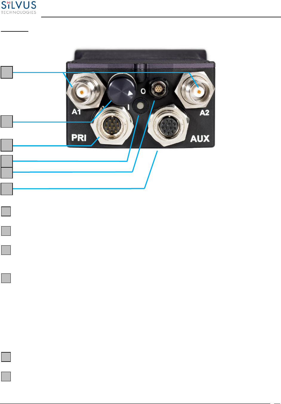
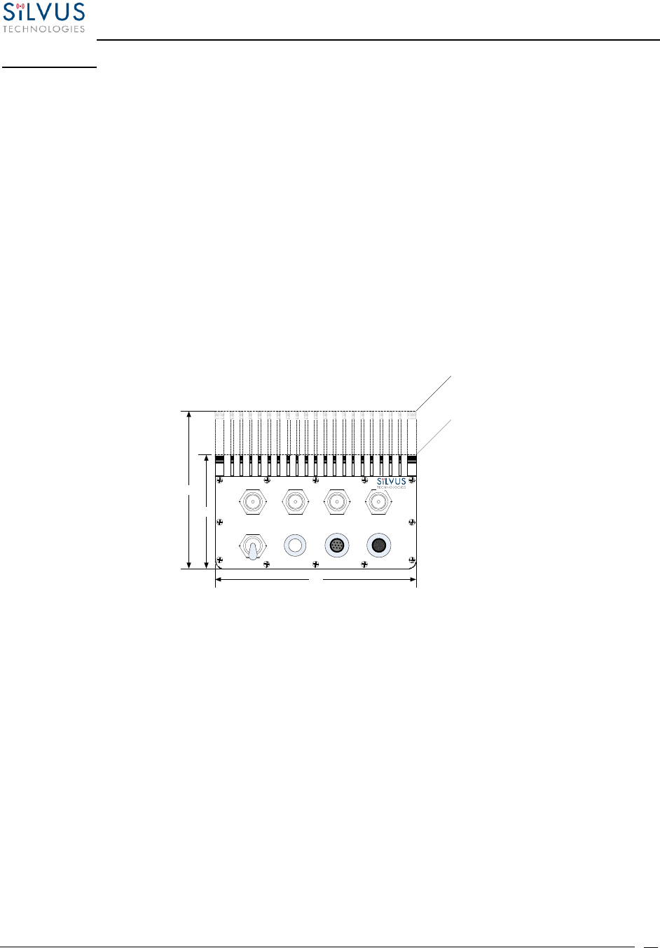
SC4200:
Figure 3 StreamCaster 4200 Ruggedized Enclosure
RF Channels 1-2 Connectors [TNC Female]
Power Switch [2-Position Rotating]
Power (EB Version Only, 9-20V), Ethernet, and Serial Port Connector [Hirose LF10WBRB-
12PD]
Bi-Color Status LED (See Section 12.1 for Troubleshooting Information)
• Red – Radio is in the process of booting up
• Flashing Green – Radio is fully booted but not wirelessly connected to any other
radio
• Green – Radio is wirelessly connected to at least one other radio
• Flashing Red – Spectrum Scan in Progress
Push-to-Talk (PTT) Connector [ODU GKCWAM-P07UB00-000L]
AUX Connector [Hirose LF10WBRB-12SD]
1
2
3
4
5
6
1
3
5
4
6
2
StreamCaster MIMO Radio User Manual 7/24/18
10017C000 Sensitive Company Material – Do Not Duplicate Page
16
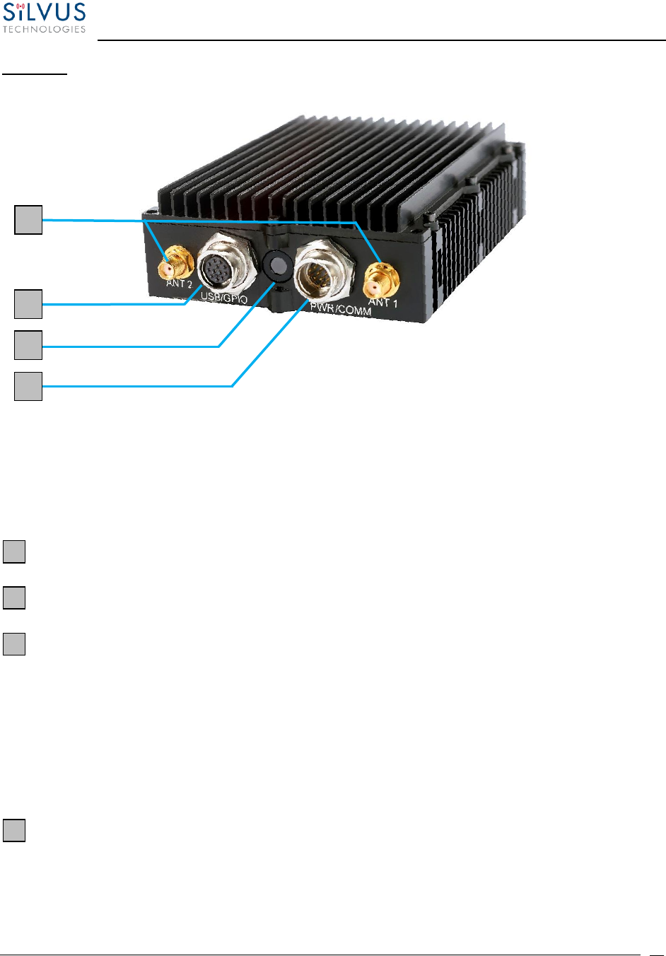
SC3822:
Figure 4 StreamCaster 3822 Ruggedized Enclosure
RF channels 1-2 Connectors [SMA Female]
USB/GPIO Connector [Hirose LF10WBRB-12SD]
Tri-Color Status LED (See Section 12.1 for Troubleshooting Information)
• Red – Radio is in the process of booting up
• Orange – Radio is fully booted but not wirelessly connected to any other radio
• Green – Radio is wirelessly connected to at least one other radio
• Flashing Red – Radio has recovered from a bad state and has reverted to factory
default settings.
Power (9-32 VDC), Ethernet, and Serial Port connector [Hirose LF10WBRB-12PD]
1
2
3
4
2
1
3
4

StreamCaster MIMO Radio User Manual 7/24/18
10017C000 Sensitive Company Material – Do Not Duplicate Page
17
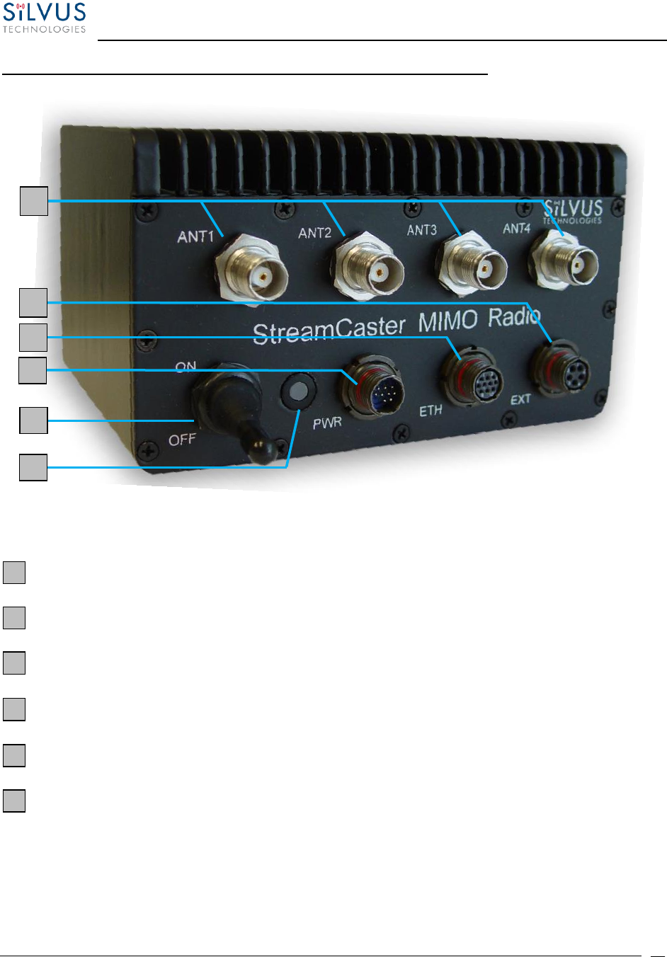
SC3500/SC3800:
Figure 5 StreamCaster 3500/3800 Ruggedized Enclosure
RF channels 1-4 connectors [TNC Female]
Ethernet connector [Mighty-Mouse 801-010-07NF7-10SA]
Power (9-20 VDC) and Serial Port connector [Mighty-Mouse 801-010-07NF7-10PA]
Tri-Color Status LED (See Section 12.1 for Troubleshooting Information)
• Red – Radio is in the process of booting up
• Orange – Radio is fully booted but not wirelessly connected to any other radio
• Green – Radio is wirelessly connected to at least one other radio
• Flashing Red – Radio has recovered from a bad state and has reverted to factory
default settings
Power Switch
1
2
3
4
5
2
3
4
5
1
StreamCaster MIMO Radio User Manual 7/24/18
10017C000 Sensitive Company Material – Do Not Duplicate Page
18
SC3500/SC3800 with EXT Connector (PA Faceplate Option):
Figure 6 StreamCaster 3500/3800 Ruggedized Enclosure
RF channels 1-4 connectors [TNC Female]
EXT PA Connector [Mighty-Mouse 801-010-07NF7-25SA]
Ethernet connector [Mighty-Mouse 801-010-07NF7-10SA]
Power (9-20 VDC) and Serial Port connector [Mighty-Mouse 801-010-07NF7-10PA]
Power Switch
Tri-Color Status LED (See Section 12.1 for Troubleshooting Information)
• Red – Radio is in the process of booting up
• Orange – Radio is fully booted but not wirelessly connected to any other radio
• Green – Radio is wirelessly connected to at least one other radio
1
2
3
4
5
6
2
3
4
1
6
5
StreamCaster MIMO Radio User Manual 7/24/18
10017C000 Sensitive Company Material – Do Not Duplicate Page
19
• Flashing Red – Radio has recovered from a bad state and has reverted to factory
default settings
4.2 Connector Pinouts
4.2.1 SC4400 Pinouts
SC4400 Power/Ethernet/Serial Connector Pinout
Enclosure PWR/COMM
(LF10WBRB-12PD)
Signal
Switchcraft Pinout
(EN3C2F16X)
1
5V OUT (For External GPS Puck)
NC
2
GND IN
2
3
GND IN
2
4
VCC IN
1
5
VCC IN
1
6
100-Base T ETH0 M2N
NC
7
100-Base T ETH0 M2P
NC
8
100-Base T ETH0 M1P
NC
9
RS232_RXD
NC
10
RS232_TXD
NC
11
RS232_GND
NC
12
100-Base T ETH0 M1N
NC
Table 2 SC4400 Power/Ethernet/Serial Connector Pinout
StreamCaster MIMO Radio User Manual 7/24/18
10017C000 Sensitive Company Material – Do Not Duplicate Page
20
SC4400 RS-232 and PS/2 (GPS) Pinout
RS-232
PS/2 (GPS)
Signal
Switchcraft Pinout
3
4
TxD
2
2
5
RxD
1
NC
NC
NC
4
NC
2
5V OUT
6
NC
NC
NC
5
5
1
Ground
3
Table 3 SC4400 Serial and GPS Pinout
SC4400 AUX Connector Pinout
Enclosure AUX
(LF10WBRB-12SD)
Signal
1
USB1_GND
2
USB1_D-
3
USB1_VBUS
4
USB2_VBUS
5
GPIO1 (PA Enable 3.3V)
6
USB2_D+
7
USB2_D-
8
RESERVED (Do Not Connect)
9
GND
10
USB1_Sense
11
USB1_D+
12
USB2_GND
Table 4 SC4400 USB/GPIO Connector Pinout (USB1 is USB 2.0 OTG, USB2 is USB 2.0 Host Mode Only)
StreamCaster MIMO Radio User Manual 7/24/18
10017C000 Sensitive Company Material – Do Not Duplicate Page
21
SC4400 PTT Connector
Enclosure PTT Connector
(ODU GKCWAM-P07UB00-000L)
Signal
1
RESERVED (Do Not Connect)
2
RESERVED (Do Not Connect)
3
AUDIO_GND
4
PTT
5
SPEAKER_OUT
6
MIC_IN
7
RESERVED (Do Not Connect)
Table 5 SC4400 PTT Connector Pinout
DC Power 9 – 20 V
Ground
12
4
2
Ground
3
DC Power 9 – 20 V
5
RJ45 Pin 1 GREEN / WHITE
RJ45 Pin 6 ORANGE
RJ45 Pin 3 ORANGE / WHITE
8
7
Grey
Black
Pink
Pink
SC4400
Power / Ethernet / Serial
Serial Rx
Serial Tx
Serial Ground
V+ for GPS Antenna
White White
11
10
Pink
Grey
Orange
Brown
Red
Yellow
Grey
White
Green
Blue
Purple
B/W striped
Black
9
RJ45 Pin 2 GREEN
6
Power
Ethernet
Serial
1
Switchcraft female
EN3C6FX
- viewed from front
6
Raised
dot
Indicates
Pin #1
5
34
1
White
2
Grey
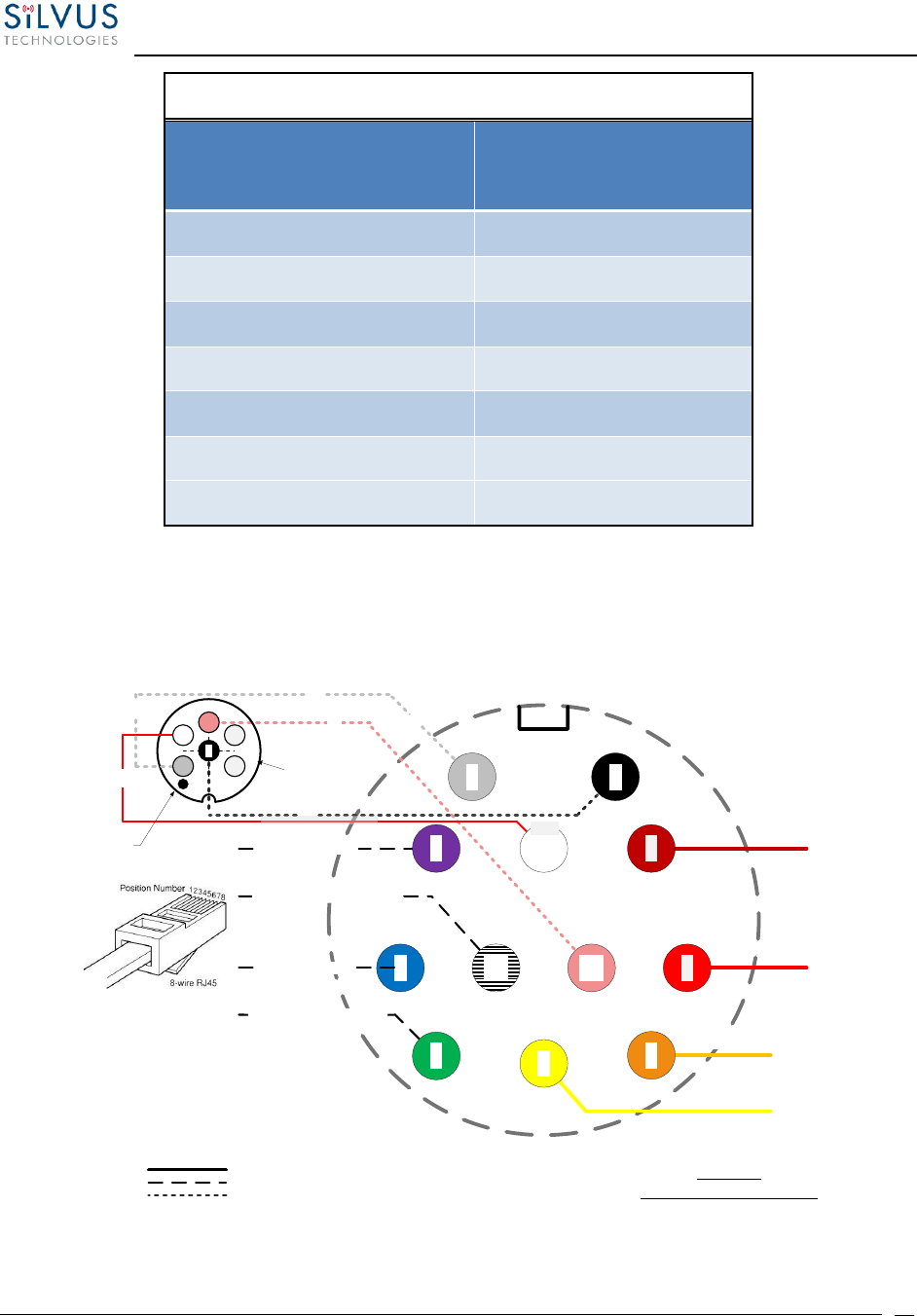
Figure 7 SC4400 Power (Optional)/Serial/Ethernet Pinout Diagram (Cable Side)
StreamCaster MIMO Radio User Manual 7/24/18
10017C000 Sensitive Company Material – Do Not Duplicate Page
22
3
5
SC4400
USB / GPIO
Serial Ground
11
10
Pink
Orange
Brown
Red
Yellow
Black
White
Green
Blue
Purple
B/W striped
Grey
USB1_GND
USB1_D-
USB1_VBUS
Ext PA Control
USB2_D+
USB2_GND
USB2_D-
Reserved (DNC)
GND
6
8
7
9
4
2
USB1_D+
1
12
USB2_VBUS
Figure 8 SC4400 AUX Pinout Diagram (Cable Side)
Figure 9 SC4400 PTT Pinout Diagram (Cable Side)
StreamCaster MIMO Radio User Manual 7/24/18
10017C000 Sensitive Company Material – Do Not Duplicate Page
23
4.2.2 SC4200 Pinouts
SC4200 Power/Ethernet/Serial Connector Pinout
Enclosure PWR/COMM
(LF10WBRB-12PD)
Signal
Switchcraft Pinout
(EN3C2F16X)
1
5V OUT (For External GPS Puck)
NC
2
GND IN (External Power Option Only)
2
3
GND IN (External Power Option Only)
2
4
VCC IN (External Power Option Only)
1
5
VCC IN (External Power Option Only)
1
6
100-Base T ETH0 M2N
NC
7
100-Base T ETH0 M2P
NC
8
100-Base T ETH0 M1P
NC
9
RS232_RXD
NC
10
RS232_TXD
NC
11
RS232_GND
NC
12
100-Base T ETH0 M1N
NC
Table 6 SC4200 Power/Ethernet/Serial Connector Pinout
SC4200 RS-232 and PS/2 (GPS) Pinout
RS-232
PS/2 (GPS)
Signal
Switchcraft Pinout
3
4
TxD
2
2
5
RxD
1
NC
NC
NC
4
NC
2
5V OUT
6
NC
NC
NC
5
5
1
Ground
3
Table 7 SC4200 Serial and GPS Pinout
StreamCaster MIMO Radio User Manual 7/24/18
10017C000 Sensitive Company Material – Do Not Duplicate Page
24
SC4200 AUX Connector Pinout
Enclosure AUX
(LF10WBRB-12SD)
Signal
1
USB1_GND
2
USB1_D-
3
USB1_VBUS
4
USB2_VBUS
5
GPIO1 (PA Enable 3.3V)
6
USB2_D+
7
USB2_D-
8
RESERVED (Do Not Connect)
9
GND
10
USB1_Sense
11
USB1_D+
12
USB2_GND
Table 8 SC4200 USB/GPIO Connector Pinout (USB1 is USB 2.0 OTG, USB2 is USB 2.0 Host Mode Only)
SC4200 PTT Connector
Enclosure PTT Connector
(ODU GKCWAM-P07UB00-000L)
Signal
1
RESERVED (Do Not Connect)
2
RESERVED (Do Not Connect)
3
AUDIO_GND
4
PTT
5
SPEAKER_OUT
6
MIC_IN
7
RESERVED (Do Not Connect)
StreamCaster MIMO Radio User Manual 7/24/18
10017C000 Sensitive Company Material – Do Not Duplicate Page
25
Table 9 SC4200 PTT Connector Pinout
DC Power 9 – 20 V
(EB Version Only)
Ground
12
4
2
Ground
3
DC Power 9 – 20 V
(EB Version Only)
5
RJ45 Pin 2
RJ45 Pin 3
RJ45 Pin 6
8
7
Grey
Black
Pink
Pink
SC4200
Power / Ethernet / Serial
Serial Rx
Serial Tx
Serial Ground
V+ for GPS Antenna
White White
11
10
Pink
Grey
Orange
Brown
Red
Yellow
Grey
White
Green
Blue
Purple
B/W striped
Black
9
RJ45 Pin 1
6
Power
Ethernet
Serial
1
Switchcraft female
EN3C6FX
- viewed from front
6
Raised
dot
Indicates
Pin #1
5
34
1
White
2
Grey
Figure 10 SC4200 Power (Optional)/Serial/Ethernet Pinout Diagram (Cable Side)
3
5
SC4200
USB / GPIO
Serial Ground
11
10
Pink
Orange
Brown
Red
Yellow
Black
White
Green
Blue
Purple
B/W striped
Grey
USB1_GND
USB1_D-
USB1_VBUS
Ext PA Control
USB2_D+
USB2_GND
USB2_D-
Reserved (DNC)
GND
6
8
7
9
4
2
USB1_D+
1
12
USB2_VBUS
Figure 11 SC4200 AUX Pinout Diagram (Cable Side)

StreamCaster MIMO Radio User Manual 7/24/18
10017C000 Sensitive Company Material – Do Not Duplicate Page
26
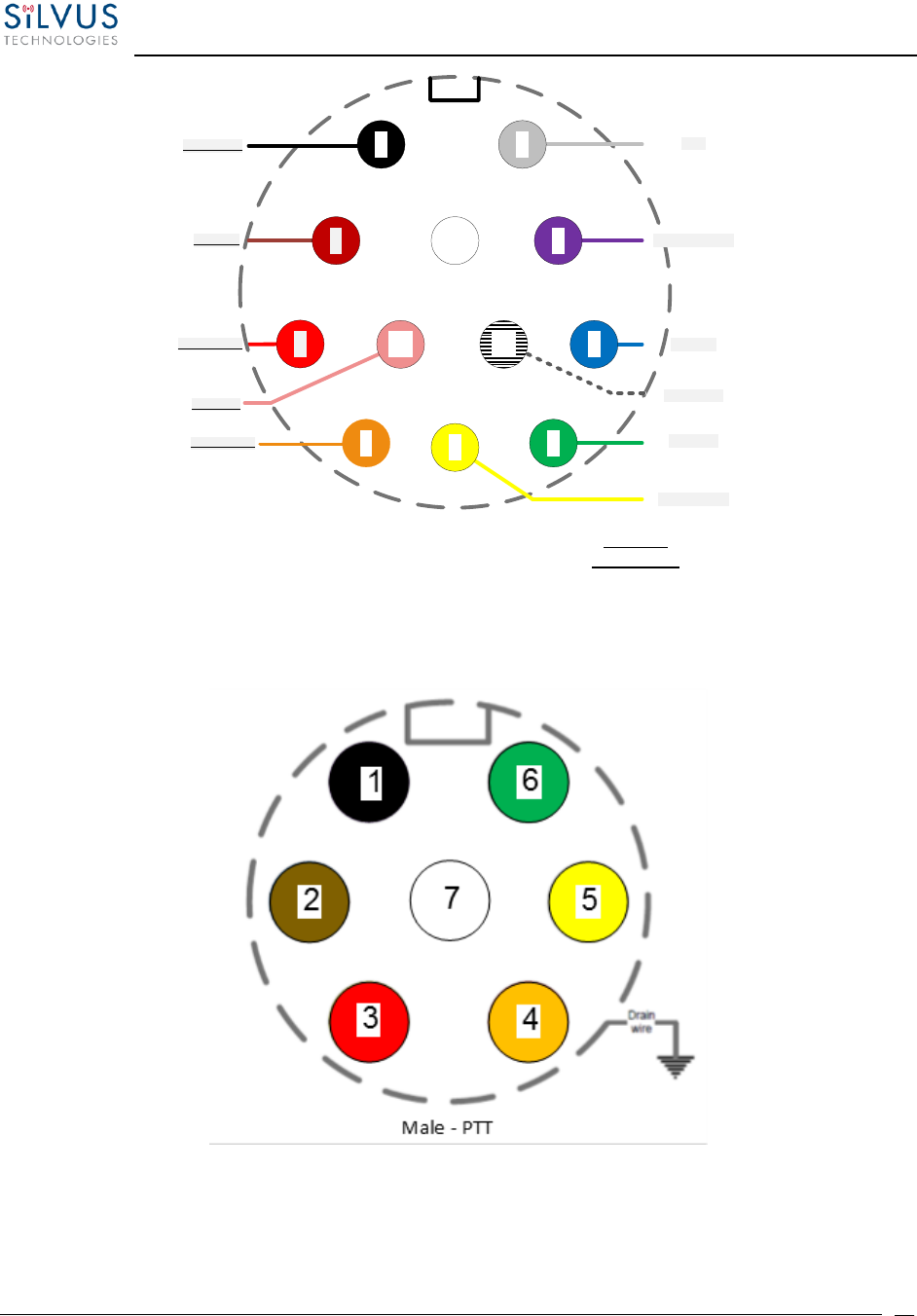
Figure 12 SC4200 PTT Pinout Diagram (Cable Side)

StreamCaster MIMO Radio User Manual 7/24/18
10017C000 Sensitive Company Material – Do Not Duplicate Page
27
4.2.3 SC3822 Pinouts
SC3822 Power/Ethernet/Serial Connector Pinout
Enclosure PWR/COMM
(LF10WBRB-12PD)
Signal
Switchcraft Pinout
(EN3C2F16X)
1
3.3V (5V on Rev. D Digital and Newer)
NC
2
GND IN
2
3
GND IN
2
4
VCC IN
1
5
VCC IN
1
6
100-Base T ETH0 M2N
NC
7
100-Base T ETH0 M2P
NC
8
100-Base T ETH0 M1P
NC
9
RS232_RXD
NC
10
RS232_TXD
NC
11
RS232_GND
NC
12
100-Base T ETH0 M1N
NC
Table 10 SC3822 Power/Ethernet/Serial Connector Pinout
SC3822 RS-232 and PS/2 (GPS) Pinout
RS-232
PS/2 (GPS)
Signal
Switchcraft Pinout
3
4
TxD
2
2
5
RxD
1
NC
NC
NC
4
NC
2
3.3V (5V on Rev. D Digital and Newer)
6
NC
NC
NC
5
5
1
Ground
3
Table 11 SC3822 Serial and GPS Pinout
StreamCaster MIMO Radio User Manual 7/24/18
10017C000 Sensitive Company Material – Do Not Duplicate Page
28
SC3822 USB/GPIO Connector Pinout
Enclosure USB/GPIO
(LF10WBRB-12SD)
Signal
1
USB_GND
2
USB_D-
3
USB_5V
4
NC
5
GPIO1 (PA Enable 3.3V)
6
GPIO2
7
GPIO3
8
3.3V
9
GND
10
USB_Sense
11
USB_D+
12
GPIO4
Table 12 SC3822 USB/GPIO Connector Pinout
SC3822 Extension Port Pinout
Pin #
Signal
Notes
1-6
VCC_IN
9V - 32V. These pins are directly wired to the VCC_IN on FPC 1.
7-10
GPIO1 – GPIO4
These GPIOs are directly wired to the GPIOs on FPC connector 2.
11-19
Reserved for Testing
Do Not Connect
20
CPU Reset (3.3V)
Wired to PS_SRST_EXT signal on FPC 1
21-54
Reserved for Testing
Do Not Connect
55
GND
56
ETH1_MX4N
Second Gigabit Ethernet Interface
57
ETH1_MX4P

StreamCaster MIMO Radio User Manual 7/24/18
10017C000 Sensitive Company Material – Do Not Duplicate Page
29
58
ETH1_MX3N
59
ETH1_MX3P
60
ETH1_MX2N
61
ETH1_MX2P
62
ETH1_MX1N
63
ETH1_MX1P
64
GND
65-68
Reserved for Testing
Do Not Connect
Table 13 SC3822 Extension Port Pinout
DC Power 9 – 32 V
Ground
12
4
2
Ground
3
DC Power 9 – 32 V
5
RJ45 Pin 2
RJ45 Pin 3
RJ45 Pin 6
8
7
Grey
Black
Pink
Pink
SC3822
Power / Ethernet / Serial
Serial Rx
Serial Tx
Serial Ground
V+ for GPS Antenna
White White
11
10
Pink
Grey
Orange
Brown
Red
Yellow
Grey
White
Green
Blue
Purple
B/W striped
Black
9
RJ45 Pin 1
6
Power
Ethernet
Serial
1
5v DC – current version
3.3v DC – earlier version
!
Switchcraft female
EN3C6FX
- viewed from front
6
Raised
dot
Indicates
Pin #1
5
34
1
White
2
Grey
Figure 13 SC3822 Power/Serial/Ethernet Pinout Diagram (Cable Side)
StreamCaster MIMO Radio User Manual 7/24/18
10017C000 Sensitive Company Material – Do Not Duplicate Page
30
1 9
11
6
8
7
5
12
102
3
4
4 3 2 1 USB_Ground
USB_Data-
USB_5V
NC
USB_Data+
GPIO1 (PA
Enable 3.3V)
GPIO4
GND
3.3V
GPIO3
GPIO2
USB_Sense
`
`
USB
SC 3822
USB/GPIO
GPIO
1
2
3
4
5
6
Black/White
Figure 14 SC3822 USB/GPIO Pinout Diagram (Cable Side)
4.2.4 SC3500/SC3800 Pinouts
SC3500/3800 Power Connector Pinout
Enclosure Pinout
(801-010-07NF7-10PA)
Signal
Switchcraft Pinout
(EN3C2F16X)
1
12V Power Return
2
2
12V Power Return
2
3
12V Power
1
4
12V Power
1
5
TxD
For Serial Comm.
6
RxD
For Serial Comm.
7
RTS
For Serial Comm.
8
CTS
For Serial Comm.
9
Ground
For Serial Comm.
StreamCaster MIMO Radio User Manual 7/24/18
10017C000 Sensitive Company Material – Do Not Duplicate Page
31
10
3.3V (5V on Rev. E Digital and Newer)
3.3VDC for GPS
Table 14 SC3500/SC3800 Power Connector Pinout
SC3500/3800 Ethernet Connector Pinout
Enclosure Pinout
(801-010-07NF7-10SA)
Signal
RJ45 Pinout
1
WHT/BLU
5
2
WHT/BRN
7
3
BRN
8
4
ORG
2
5
WHT/GRN
3
6
WHT/ORG
1
7
BLU
4
8
GRN
6
9
NC
NC
10
NC
NC
Table 15 SC3500/SC3800 Ethernet Connector Pinout
SC3500/3800 EXT Connector Pinout (PA Faceplate Option Only)
Enclosure Pinout
(801-010-07NF7-25SA)
Signal
1
PA On (+3.3V)
2
Ground
3
NC
4
NC
5
NC
Table 16 SC3500/SC3800 EXT Connector Pinout
StreamCaster MIMO Radio User Manual 7/24/18
10017C000 Sensitive Company Material – Do Not Duplicate Page
32
SC3500/3800 RS-232 and PS/2 (GPS) Pinout
RS-232
PS/2 (GPS)
Signal
Switchcraft Pinout
3
4
TxD
2
2
5
RxD
1
7
NC
RTS
4
NC
2
3.3V (5V on Rev. E Digital and Newer)
6
8
NC
CTS
5
5
1
Ground
3
NA
NA
LED Ground
NA
NA
NA
Green
NA
NA
NA
Red
NA
Table 17 SC3500/SC3800 Serial and GPS Pinout
StreamCaster MIMO Radio User Manual 7/24/18
10017C000 Sensitive Company Material – Do Not Duplicate Page
33
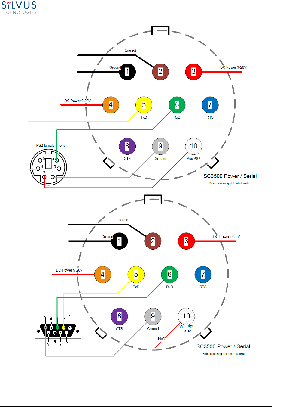
Figure 15 SC3500/SC3800 Power/Serial Pinout Diagram (Cable Side) for GPS (Top) and RS-232 (Bottom)

StreamCaster MIMO Radio User Manual 7/24/18
10017C000 Sensitive Company Material – Do Not Duplicate Page
34
Figure 16 SC3500/SC3800 Ethernet Pinout Diagram (Cable Side)
Figure 17 SC3500/SC3800 EXT Pinout Diagram (Cable Side)

StreamCaster MIMO Radio User Manual 7/24/18
10017C000 Sensitive Company Material – Do Not Duplicate Page
35
4.3 Mechanical and Operating Specifications
SC4400:
Mechanical
• Ambient Temp.
-40° to +65° C
• IP Rating
IP-67 (Dust / Immersion in Water up to 1m)**
• Dimensions
5.25” x 4.5” x 1.8” (Excluding Connectors)
• Weight
2.5 lbs. (40 oz./1.13 kg.)
• Color
Black Anodized
• Mounting
4-Hole Mounting Patterns
Power
• Voltage/Current
•
9 – 20 VDC (± 5%), 5A
• Power Consumption
8 W – 43 W @ 8 W TX Power
1 W – 24 W @ 1 W TX Power
• Optional External Power Supply (for indoor only)
12VDC, 5A
Interfaces
• RF
4 x TNC(f)
[ N(f) Optional ]
• Primary
Ruggedized Circular Connector
[ 1 x Ethernet, 1 x RS232, DC Input ]
• Auxiliary
Ruggedized Circular Connector
[ 1 x USB 2.0 Host, 1 x USB 2.0 OTG ]
• PTT (Push-to-Talk)
Ruggedized Break away Connector(Front Panel)
• Status Indicator
Tri-Color LED
• Management Interface
Web-Based StreamScape™ Network Manager
Mechanical – OEM
• Dimensions
4.29” x 3.3” x 0.82”
• Weight
9.1 oz (w/ Outer Shields)
• RF Connectors
SMP (m)
(**) Must have all connectors mated with IP67+ cables/antennas

StreamCaster MIMO Radio User Manual 7/24/18
10017C000 Sensitive Company Material – Do Not Duplicate Page
36
SC4200:
Mechanical
• Ambient Temp.
-40° to +65° C
• IP Rating
IP-67 (Dust / Immersion in Water up to 1m)**
• Dimensions
4.00” x 2.63” x 1.51” (Excluding Connectors)
• Weight
0.94 lbs. (15 oz./0.43 kg.)
• Color
Black Anodized
• Mounting
4-Hole Mounting Patterns (Through-Hole)
Power
• Voltage/Current
9 – 20 VDC (± 5%), 5A
• Power Consumption
4.8 W – 24 W
• Battery Life
Up to 12 Hours (6.8Ah MBITR Battery)
• Power Options
Twist-Lock Battery or Front Panel
• Optional External Power Supply (for indoor only)
12VDC, 5A
Interfaces
• RF
TNC(f) (2 Each)
• Primary
Ruggedized Circular Connector (Front Panel)
1 x Ethernet, 1x RS232, DC Input (Optional)
• Auxiliary
Ruggedized Circular Connector (Front Panel)
1 x USB 2.0 Host, 1 x USB 2.0 OTG
• PTT (Push-to-Talk)
Ruggedized Circular Connector (Front Panel)
• Status Indicator
Bi-Color LED
• Management Interface
Web-Based StreamScape™ Network Manager
Mechanical – OEM
• Dimensions
3.61” x 2.15” x 0.71”
• Weight
4.1 oz (w/ Outer Shields)
• RF Connectors
SMP (m)
(**) Must have all connectors mated with IP67+ cables/antennas
StreamCaster MIMO Radio User Manual 7/24/18
10017C000 Sensitive Company Material – Do Not Duplicate Page
37
SC3822:
Environmental
Standard Temperature
Extended Temperature
• Operating Temp.
-40° - +55° C
-40° - +65° C
• IP Rating
(Ingress Protection)
IP-67 (Dust / Immersion in water up to 1m)*
*Must have all connectors mated and use IP67 or better cables/antennas
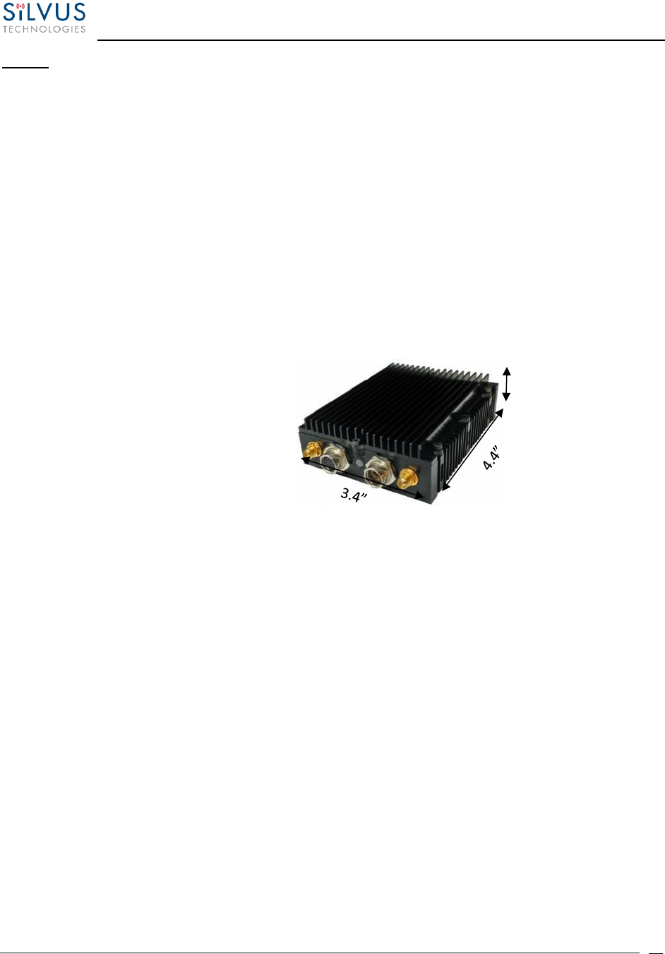
Mechanical – Chassis
Standard
Extended Temperature
• Dimensions
4.4” x 3.4” x 1.3”
4.4” x 3.4” x 2.0”
• Weight
1.0 lbs. (0.45 kg./16 oz.)
1.2 lbs. (0.54 kg./19.2 oz.)
• Color
a. Black anodized
b. FED-STD-595B-34094 (green 383)
• Mounting
4-hole mounting patterns (Through-hole)
Connectors
• RF
SMA (f) (2 each)
• Data / Control
Ethernet (Gigabit for OEM, 100 Base-T for Enclosed), RS232, USB
• Power
Hirose LF Series Circular Connector (Front Panel)
Samtec QSH (Expansion)
Controls and Indicators
• Status Indicator
Tri-Color LED
Power Requirements
• Voltage
9 – 32 VDC
• Consumption
6W – 16W (Duty Cycle and Frequency Dependent)
24.5 W – 80% Tx Duty Cycle
Mechanical – OEM Board Stack
• Dimensions
3.3” x 2.9” x 0.5” L x W x H
• Weight
3 oz
• RF Connector
SMP (m)
*Standard Temperature enclosure shown.
Extended Temp has height of 2”.
1.3”
Inch
StreamCaster MIMO Radio User Manual 7/24/18
10017C000 Sensitive Company Material – Do Not Duplicate Page
38
SC3500/SC3800:
Environmental
Standard
Extended Temperature
• Operating Temp.
-40° - +55° C
-40° - +65° C
• IP Rating
IP-67 (Dust / Immersion in water up to 1m)*
(Ingress Protection)
*Must have all connectors mated and use IP67 or better cables/antennas
Mechanical – Chassis
Standard
Extended Temperature
• Dimensions
3.25” x 5.75” x 4”
H x L x W
4.5” x 5.75” x 4”
H x L x W
• Weight
3.7 lbs. (1.68 kg./59.2 oz.)
4 lbs. (1.81 kg./64 oz.)
• Color
c. FED-STD-595B-34094 (green 383)
d. Black anodized
e. CARC (Chemical Agent Resistant Coating)
• Mounting
4-hole mounting patterns (non-penetrating)
located on both rear and bottom sides
Connectors
• RF
TNC (f) (4 each)
• Data / Control
Ethernet cable, Mighty-Mouse 801 Heavy-Duty, Double-Start 10
conductor (f)
• Power
Mighty-Mouse 801 Heavy-Duty, Double-Start 10 conductor (m)
(RS232 / GPS Support)
Controls and Indicators
• Power
On / Off Toggle with detent
• Status Indicator
Tri-Color LED
Power Requirements
• Voltage
9 – 20 VDC
• Consumption
12W – 22.5W (Duty Cycle and Frequency Dependent)
24.5 W – 80% Tx Duty Cycle
Mechanical – OEM Board Stack
• Dimensions
1.9” x 5.25” x 2.9” H x L x W
• Weight
8 oz
• RF Connector
SMP (m)
• Data Connector
Harwin M80 8-pin (m), (RS232/GPS optional)
• Power Connector
Harwin M80 8-pin
5.75
4.50
3.25
Extended Temperature Variant
Standard Temperature Variant
ANT1 ANT4ANT3ANT2
STATUS PWROFF ETH
ON
StreamCaster MIMO Radio User Manual 7/24/18
10017C000 Sensitive Company Material – Do Not Duplicate Page
39
4.3.1 SC4400 Enclosure Mechanical Drawing
Figure 18 SC4400 Mechanical Drawing (top) and Mounting Pattern (bottom)

StreamCaster MIMO Radio User Manual 7/24/18
10017C000 Sensitive Company Material – Do Not Duplicate Page
40
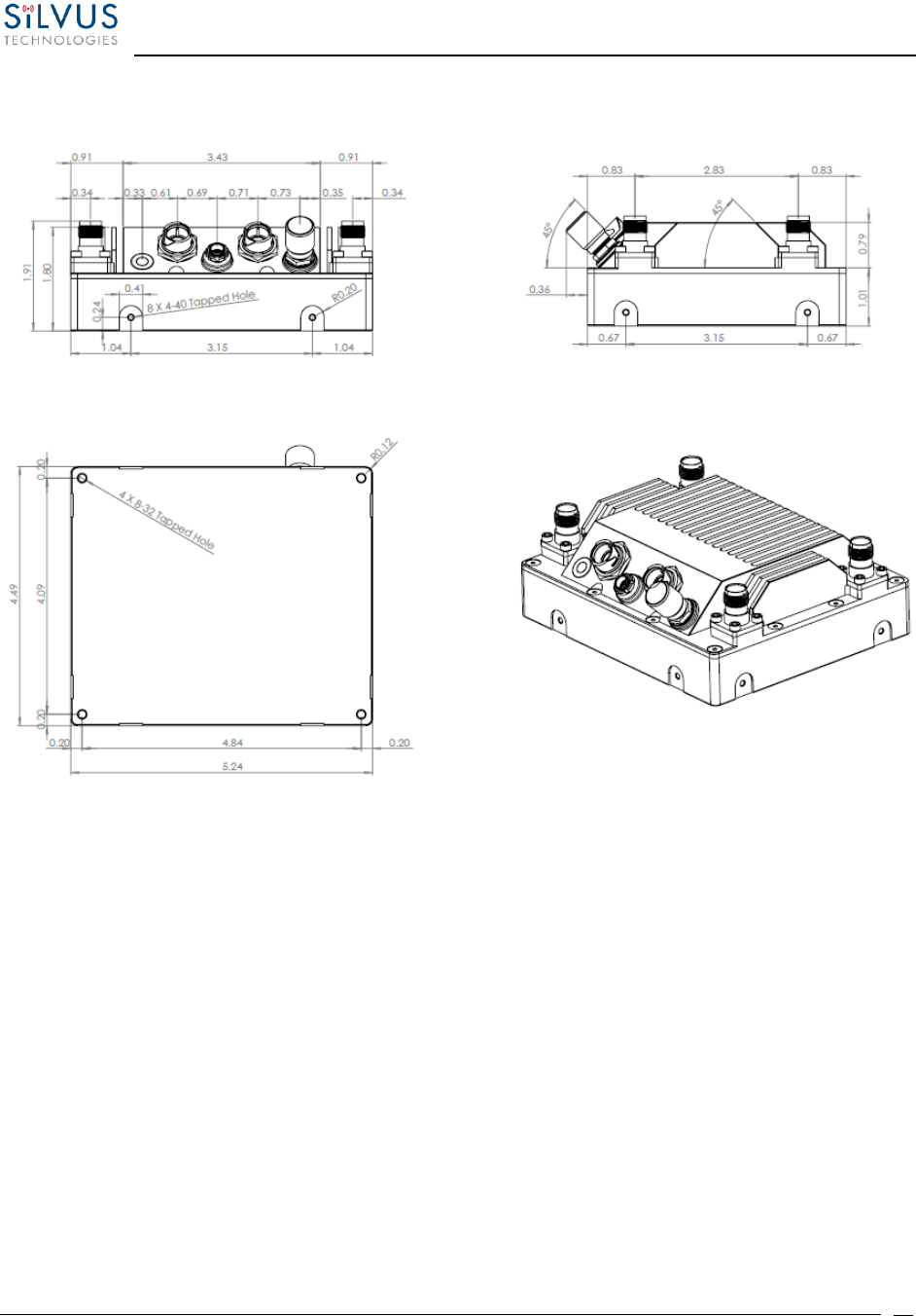
4.3.2 SC4200 Enclosure Mechanical Drawing
Figure 19 SC4200 Mechanical Drawing (top) and Mounting Pattern (bottom)
StreamCaster MIMO Radio User Manual 7/24/18
10017C000 Sensitive Company Material – Do Not Duplicate Page
41
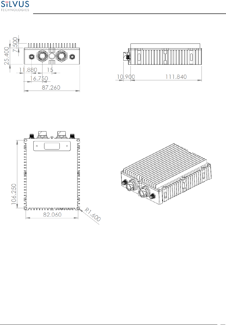
4.3.3 SC3822 Enclosure Mechanical Drawing
Figure 20 SC3822 Mechanical Drawing (top) and Mounting Pattern (bottom)
StreamCaster MIMO Radio User Manual 7/24/18
10017C000 Sensitive Company Material – Do Not Duplicate Page
42
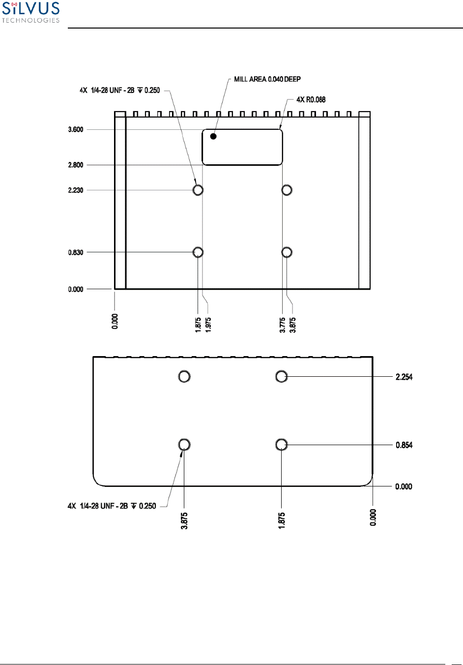
4.3.4 SC3500/SC3800 Phase II Enclosure Mounting Pattern
Figure 21 SC3500/SC3800 Phase II Enclosure Mounting Pattern for Back of Enclosure (top) and Bottom of Enclosure (bottom)

StreamCaster MIMO Radio User Manual 7/24/18
10017C000 Sensitive Company Material – Do Not Duplicate Page
43
4.3.5 SC3500/ SC3800 Phase III Enclosure Mounting Pattern
Figure 22 SC3500/SC3800 Phase III Enclosure Mounting Pattern for Back of Enclosure (top) and Bottom of Enclosure (bottom)

StreamCaster MIMO Radio User Manual 7/24/18
10017C000 Sensitive Company Material – Do Not Duplicate Page
44
4.4 SC4400 Specifications
General
• Waveform
Mobile Networked MIMO (MN-MIMO™)
• Modulation
BPSK, QPSK, 16-QAM, 64-QAM
• Channel Bandwidth
5, 10 & 20 MHz (1.25*, 2.5*)
• Encryption
DES Standard, AES/GCM 128/256 Optional (FIPS 140-2),
Suite B
• Tuning Step Size
1 KHz
• Data Rates
100+ Mbps (Adaptive)
• Error Correction
1/2, 2/3, 3/4, 5/6
• Antenna Processing
Spatial Multiplexing, Space-Time Coding,
TX Eigen Beamforming, RX Eigen Beam Forming
• No. of Spatial Streams
1-2
• No. of Antennas
• Total Power Output
4
1mW – 4W (variable)
(up to 8W Effective w/ TX Beamforming)
Performance
• Latency
7ms Average (20MHz BW)
• Sensitivity
-102 dBm @ 5MHz BW
• Frequency Bands
Bands from 400MHz to 6GHz Available
Dual Band Optional
• Onboard Storage
64 GB*
Frequency Band Options
Band (Freq. Code)
Frequency Range
Band (Freq. Code)
Frequency Range
UHF (042)
400-450
Low C Band (455)
4400-4700
ISM 900 (091)*
902-928
Federal C-1 (467)
4400-4940
L Band (137)
1350-1390
Federal C-2 (469)*
4400-4990
Upper L (181)
1780-1850
High C Band (485)
4700-5000
Broadcast A (209)
1980-2200
5.2GHz ISM (520)
5150-5250
Broadcast B (206)
2025-2110
5.8GHz ISM (580)
5725-5875
Federal S (225)
2200-2300
S Band (235)
2200-2500
2.4GHz ISM (245)
2400-2500
(All bands listed in MHz)
Note: If band of interest is not listed, please contact a sales representative
Footnote: (*) in development

StreamCaster MIMO Radio User Manual 7/24/18
10017C000 Sensitive Company Material – Do Not Duplicate Page
45
4.5 SC4200 Specifications
General
• Waveform
Mobile Networked MIMO (MN-MIMO™)
• Modulation
BPSK, QPSK, 16-QAM, 64-QAM
• Channel Bandwidth
5, 10 & 20 MHz (1.25*, 2.5*)
• Encryption
DES Standard, AES/GCM 128/256 Optional (FIPS 140-2),
Suite B
• Tuning Step Size
1 KHz
• Data Rates
100+ Mbps (Adaptive)
• Error Correction
1/2, 2/3, 3/4, 5/6
• Antenna Processing
Spatial Multiplexing, Space-Time Coding,
TX Eigen Beamforming, RX Eigen Beam Forming
• No. of Spatial Streams
1-2
• No. of Antennas
• Total Power Output
2
1mW – 4W (variable)
(up to 8W Effective w/ TX Beamforming)
Performance
• Latency
7ms Average
• Sensitivity
-99 dBm @ 5MHz BW
• Frequency Bands
Bands from 400MHz to 6GHz Available
Dual Band Optional
• Onboard Storage
64 GB*
Frequency Band Options
Band (Freq. Code)
Frequency Range
Band (Freq. Code)
Frequency Range
UHF (042)
400-450
Low C Band (455)
4400-4700
ISM 900 (091)*
902-928
Federal C-1 (467)
4400-4940
L Band (137)
1350-1390
Federal C-2 (469)*
4400-4990
Upper L (181)
1780-1850
High C Band (485)
4700-5000
Broadcast A (209)
1980-2200
5.2GHz ISM (520)
5150-5250
Broadcast B (206)
2025-2110
5.8GHz ISM (580)
5725-5875
Federal S (225)
2200-2300
S Band (235)
2200-2500
2.4GHz ISM (245)
2400-2500
(All bands listed in MHz)
Note: If band of interest is not listed, please contact a sales representative
Footnote: (*) in development

StreamCaster MIMO Radio User Manual 7/24/18
10017C000 Sensitive Company Material – Do Not Duplicate Page
46
SC4400/SC4200 PTT Specifications
• Supported Mic Type
Moving Coil or
Condenser (Software
Configurable)
• Max Avg. Speaker Output Power
2.65W with 4 Ohm
Speaker Impedance
• MIC Bias
2.15V or 3V (Software
Configurable); Applied
via a 2K Ohm Resistor
• Recommended Speaker Impedance (Handset)
4 Ohm to 16 Ohm
• Recommended Speaker Impedance (Headset)
75 Ohm to 300 Ohm
• Recommended MIC impedance
<= 1K Ohm
• Peak Speaker Output Voltage
5.5V
• Absolute MIC Input Voltage
3.3V

StreamCaster MIMO Radio User Manual 7/24/18
10017C000 Sensitive Company Material – Do Not Duplicate Page
47
4.6 SC3822 Specifications
General
• Waveform
Mobile Networked MIMO (MN-MIMO™)
• Modulation
BPSK, QPSK, 16-QAM, 64-QAM
• Channel Bandwidth
5, 10 & 20 MHz (1.25*, 2.5*)
• Encryption
DES Standard, AES 128/256 Optional (FIPS 140-2)
• Frequency Stability
1 PPM over temp -40° - +85° C
• Tuning Step Size
1 KHz
• Data Rates
85 Mbps UDP & 70 Mbps TCP
• Error Correction
1/2, 2/3, 3/4, 5/6
• Antenna Processing
Spatial Multiplexing, Space-Time Coding,
RX Eigen Beam Forming
• No. of Spatial Streams
1-2
• No. of Antennas
• Total Power Output
2
10mW – 500mW (variable)
Performance
• Latency
7 ms average
• Sensitivity
Varies with MCS index
Maximum = -99 dBm (5MHz BW, MCS0)
(5 MHz BW, MCS 0)
Frequency Band Specifics
Please note, this table reflects standard frequency bands available, additional bands are frequently added as
demands dictate. If your band of interest is not listed, please contact your sales person. (All bands listed in MHz)
Low Band
High Band
UHF
400-450 *
C-1 Band
4400-4700
ISM 900
902-928 *
C-2 Band
4700-5000
L Band
1350-1390
C-3 Band
5727-5852
Broadcast A
1980-2200
UNII-1 Band
5150-5250
Broadcast B
2025-2110

StreamCaster MIMO Radio User Manual 7/24/18
10017C000 Sensitive Company Material – Do Not Duplicate Page
48
Federal ‘S’
2200-2300*
ISM2400
Federal ‘S’ +
2.4GHZ ISM
2400-2483*
2200-2500
Footnote: (*) in development
4.7 SC3500 Specifications
General
• Radio Type
MIMO Coded-OFDM
• Subcarrier Modulation
BPSK, QPSK, 16-QAM, 64-QAM
• Channel Bandwidth
5, 10 & 20 MHz
• Encryption
DES Standard, AES 128/256 Optional
• Frequency Stability
1 PPM over temp -40° - +85° C
• Tuning Step Size
1 KHz
• Data Rates
85 Mbps UDP & 70 Mbps TCP
• Error Correction
1/2, 2/3, 3/4, 5/6
• Antenna Processing
Spatial Multiplexing, Space-Time Coding,
Eigen Beam Forming
• No. of Spatial Streams
1-4
• No. of Antennas
4
• Total Power Output
10mW – 1W (variable)
Performance
• Latency
7 ms average
• Sensitivity
Varies with MCS index
Maximum = -102 dBm (5 MHz BW, MCS 0)

StreamCaster MIMO Radio User Manual 7/24/18
10017C000 Sensitive Company Material – Do Not Duplicate Page
49
Frequency Band Specifics
S Band
C Band
• Frequency Code ‘245540’
2.385 – 2.490 GHz
4.960 – 5.875 GHz
2.400 – 2.500 GHz
4.940 – 5.875 GHz
• Frequency Code ‘245551’
•
2.400 – 2.500 GHz
5.150 – 5.875 GHz
• Frequency Code ‘243578’
•
2.417 – 2.457 GHz
5.735 – 5.840 GHz
4.8 SC3800 Specifications
General
• Radio Type
MIMO Coded-OFDM
• Subcarrier Modulation
BPSK, QPSK, 16-QAM, 64-QAM
• Channel Bandwidth
5, 10 & 20 MHz (1.25*, 2.5*)
• Encryption
DES Standard, AES 128/256 Optional
• Frequency Stability
1 PPM over temp -40° - +85° C
• Tuning Step Size
1 KHz
• Data Rates
85 Mbps UDP & 70 Mbps TCP
• Error Correction
1/2, 2/3, 3/4, 5/6
• Antenna Processing
Spatial Multiplexing, Space-Time Coding,
RX Eigen Beam Forming
• No. of Spatial Streams
1-4
• No. of Antennas
• Total Power Output
4
10 mW – 1 W (variable)
Performance
• Latency
7 ms average
• Sensitivity
Varies with MCS index
Maximum = -102 dBm (5MHz BW, MCS 0)
(5 MHz BW, MCS 0)

StreamCaster MIMO Radio User Manual 7/24/18
10017C000 Sensitive Company Material – Do Not Duplicate Page
50
Frequency Band Specifics
Please note, this table reflects standard frequency bands available, additional bands are frequently added as
demands dictate. If your band of interest is not listed, please contact your sales person. (All bands listed in
MHz)
Low Band
High Band
UHF
400-450 *
C-1 Band
4400-4700
ISM 900
902-928 *
C-2 Band
4700-5000
L Band
1350-1390
C-3 Band
5727-5852
Broadcast A
1980-2200
UNII-1 Band
5150-5250
Broadcast B
2025-2110
Federal ‘S’
2200-2300*
ISM2400
Federal ‘S’ +
2.4GHZ ISM
2400-2483*
2200-2500
Footnote: (*) in development
5. Web Interface
5.1 Getting Started
Connect a laptop to the StreamCaster radio using the supplied Ethernet cable and turn on the
radio. Users can type “ping <IPaddress>” in order to determine whether the radio is fully booted.
A web configuration will then be available by typing the radio IP address in a web browser. Please
ensure that your laptop is on the same subnet as the radio (172.20.xx.xx by default). Users will
be directed to the Basic Configuration page. (See Figure 23)
StreamCaster MIMO Radio User Manual 7/24/18
10017C000 Sensitive Company Material – Do Not Duplicate Page
51
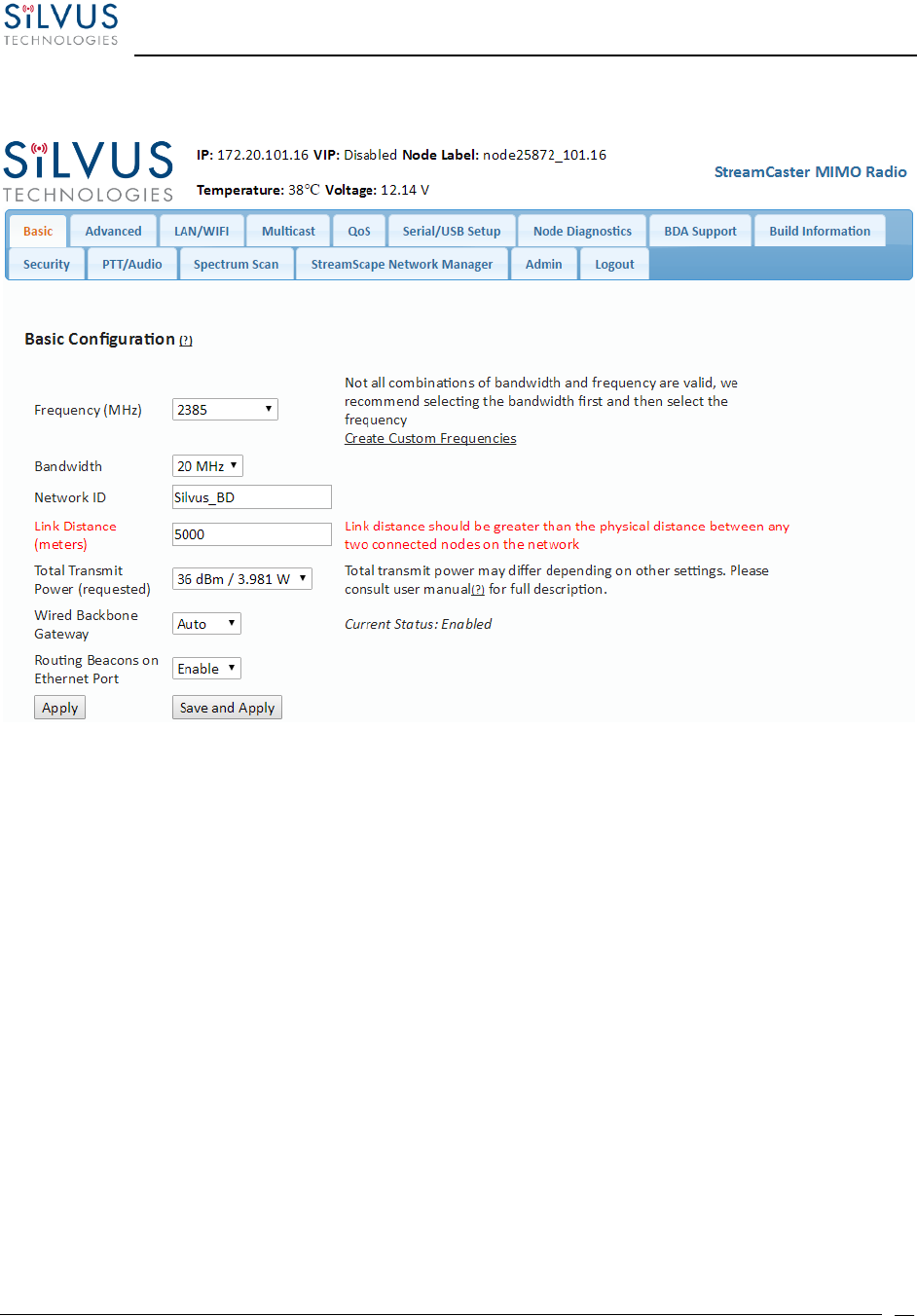
5.1.1 Basic Configuration
Figure 23 Basic Configuration Page
This page is used to set basic configurations. A brief description of each parameter is given below.
• Frequency: This defines the frequency of the signal. There is a drop-down menu for
frequency selection. The frequency choices will vary depending on the StreamCaster
model(s) you are using. Please see Section 8 for “Custom Frequency Plan” access and
installation instructions.
• Bandwidth: This defines the RF bandwidth of the signal.
• Network ID: Network ID allows for clusters of radios to operate in the same channel,
but remain independent. A radio with a given Network ID will only communicate with
other radios with the same Network ID.
• Link Distance: Set to an approximate maximum distance between any two nodes in meters,
e.g., 5000 for 5km (default). It is important to set the link distance to allow enough time for
packets to propagate over the air. Failing to set the link distance to an approximate maximum
distance can result in over the air collisions and a degradation of performance. It is
recommended to set the link distance 10-15% greater than the actual maximum distance.

StreamCaster MIMO Radio User Manual 7/24/18
10017C000 Sensitive Company Material – Do Not Duplicate Page
52
• Total Transmit Power: This defines the total power of the signal (power is divided
equally between the radio antenna ports). There is also an option to ‘Enable Max
Power’ which will allow the radio to push to the highest TX power it can support. This
will be slightly different on each radio.
• Wired Backbone Gateway: This setting pertains to wired backbone functionality (See
Section 7: Wired Backbone). For normal operation, set Wired Backbone Gateway to
‘Auto’. If multiple radios will be connected to a wired backbone, all radios on the
backbone should be set to ‘Auto’.
• Routing Beacons on Ethernet Port: For radios to be able to communicate and transfer
data over a wired link, routing information needs to be sent over the wireline. These
packets are broadcast packets that are sent even if there is only one radio on the
network. If wired backbone is not being utilized, the user can disable these routing
beacons to prevent loading their local network with these routing packets.
• Apply: Apply the new values. Values will change back to the default setting after
reboot.
• Save and Apply: Apply the new values and set the new values as the default.
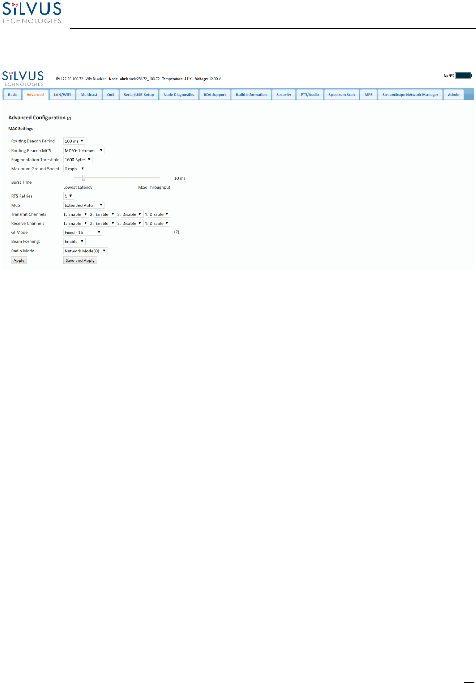
StreamCaster MIMO Radio User Manual 7/24/18
10017C000 Sensitive Company Material – Do Not Duplicate Page
53
5.1.2 Advanced Configuration
Figure 24 Advanced Configuration Page
This page is used to set the advanced settings. A brief description of each parameter is given below.
MAC Settings:
• Routing Beacon Period: Controls how often routing beacons are sent to other radios. A lower
Routing Beacon Period results in faster reaction to topology changes. A lower Routing Beacon
Period also adds more overhead to the network which scales with the number of nodes in the
network. For larger networks, a larger Routing Beacon Period is recommended. Default value is
100ms.
• Routing Beacon MCS: Select the MCS that routing beacons are sent at. Higher MCS values require
less network overhead and may be beneficial for larger networks. The drawback is that the link
will break when the Routing Beacon MCS can no longer be supported.
• Fragmentation Threshold: Allows user to determine the minimum over-the-air packet size in
bytes. Smaller packet size can improve performance in high mobility while a larger packet size will
allow for more throughput. (1600 bytes default).

StreamCaster MIMO Radio User Manual 7/24/18
10017C000 Sensitive Company Material – Do Not Duplicate Page
54
• Maximum Ground Speed: This setting improves performance in high mobility scenarios where
the wireless channel may change rapidly. Setting this value to an unnecessarily high value may
have an impact as high as 25 percent on overall achievable throughput.
• Burst Time: The burst time determines the maximum amount of time each node is allowed to
transmit at once. A larger burst time will provide higher throughput at the cost of higher latency.
On the other hand, a smaller burst time will provide less latency at the cost of less throughput.
The throughput values shown in Table 18 and
Table 20 assume the minimum burst time.
• RTS Retries: A node wishing to send data initiates the process by sending a request to send
message (RTS). The destination node replies with a clear to send (CTS) message. Any other node
that receives the RTS or CTS message will refrain from sending data for a given time. In larger
networks, there is a higher probability of collisions occurring when an RTS is sent out. This field
defines the number of retries before a packet is dropped. A lower value will result in faster
handoffs in mobile situations.
• MCS: Choose the modulation and coding scheme (MCS). If this is set as AUTO, the radio will
dynamically cycle between a subset of the modes depending on the quality of the link. This is
the recommended setting for most users and will provide the maximum data rate that the link
can support. The EXTENDED AUTO mode includes 64QAM rate modes on top of those included
in the AUTO mode. Table 18 and
Table 20 below show the estimated UDP data rate and sensitivity for each MCS. This table
assumes a 20MHz bandwidth, 1000 meter link distance and 1600 byte fragmentation threshold.
• Transmit Channels: Allows user to Enable or Disable each channel on the radio for TX.
• Receive Channels: Allows user to Enable or Disable each channel on the radio for RX.
• GI Mode: This feature can be used to improve performance in environments where long delay
spread is present and causing intersymbol interference
(https://en.wikipedia.org/wiki/Intersymbol_interference). This setting allows the radio to vary
its Guard Interval (https://en.wikipedia.org/wiki/Guard_interval) to allow for longer delay
spread. When set to ‘Extended Auto – GI’, the radio will choose between the regular GI, and the
user specified longer GI (Cyclic Prefix Length in the next setting) depending on channel
conditions.

StreamCaster MIMO Radio User Manual 7/24/18
10017C000 Sensitive Company Material – Do Not Duplicate Page
55
• Beamforming (SC4200/SC4400 Only): Enable or disable TX Beamforming (Up to 2X increase in
range when enabled)
• Radio Mode: Switch between Network mode and PHY Diagnostics. If the value equals 0, it is in
Network mode; if the value equals 1, it is in PHY Diagnostics. PHY Diagnostics mode is only relevant
for users who wish to run diagnostic tests on the radio.
• Apply: Applies the new values but does not save them to flash.
• Save and Apply: Save the new values to flash and apply.
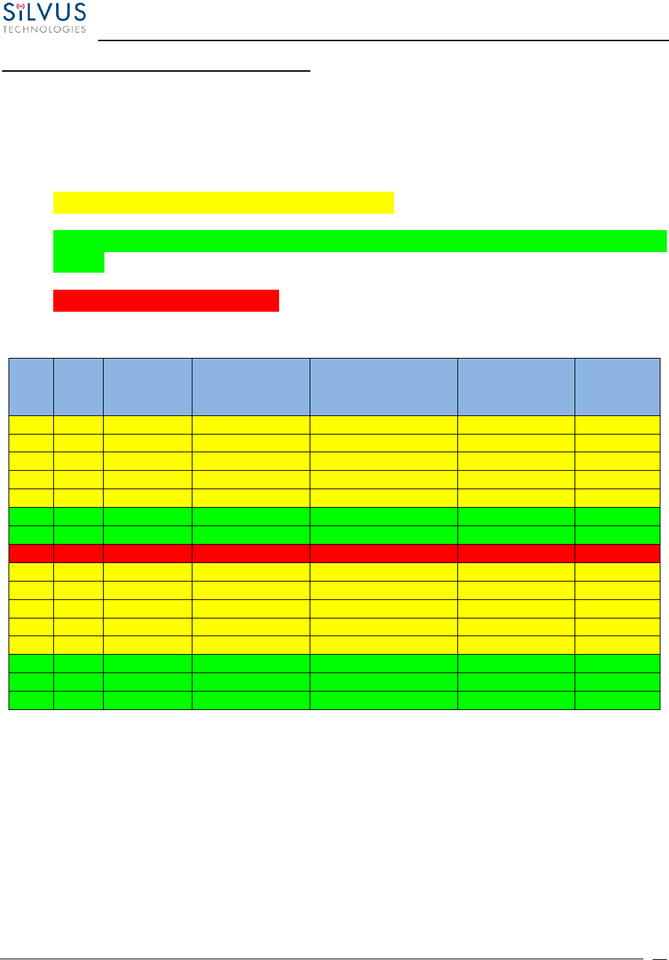
StreamCaster MIMO Radio User Manual 7/24/18
10017C000 Sensitive Company Material – Do Not Duplicate Page
56
Modulation Modes and Receiver Sensitivity
• Note that listed sensitivity values were measured using a controlled and cabled setup.
Actual results may vary by +/- 2dB. Table assumes link distance of 5000m. 10ms, 20ms,
and 40ms burst time for 20, 10, and 5MHz bandwidth respectively. 1600 byte
Fragmentation Threshold.
• * Modes supported under the AUTO MCS option.
• * Modes supported under the EXTENDED AUTO MCS option in addition to AUTO MCS
modes.
• *Modes currently not supported
NSS
MCS
Coding Rate
PHY Throughput
(Mbps)
UDP User Throughput
(Mbps)
SC4400/3500/3800
Sensitivity
SC4200/3822
Sensitivity
1
0
BPSK 1/2
1.625
1.03
-102
-99
1
1
QPSK 1/2
3.25
2.06
-100
-97
1
2
QPSK 3/4
4.875
3.09
-97
-94
1
3
16-QAM 1/2
6.5
4.12
-95
-92
1
4
16-QAM 3/4
9.75
6.18
-92
-89
1
5
64 QAM 2/3
13
8.25
-87
-84
1
6
64 QAM 3/4
14.625
9.28
-85
-82
1
7
64 QAM 5/6
16.25
10.30
-80
-77
2
8
BPSK 1/2
3.25
2.06
-100
-97
2
9
QPSK 1/2
6.5
4.12
-97
-94
2
10
QPSK 3/4
9.75
6.18
-94
-91
2
11
16-QAM 1/2
13
8.25
-91
-89
2
12
16-QAM 3/4
19.5
12.38
-88
-85
2
13
64 QAM 2/3
26
16.21
-84
-81
2
14
64 QAM 3/4
29.25
17.62
-82
-79
2
15
64 QAM 5/6
32.5
18.94
-77
-74
Table 18 MCS vs. Sensitivity Chart (5MHz Bandwidth)*
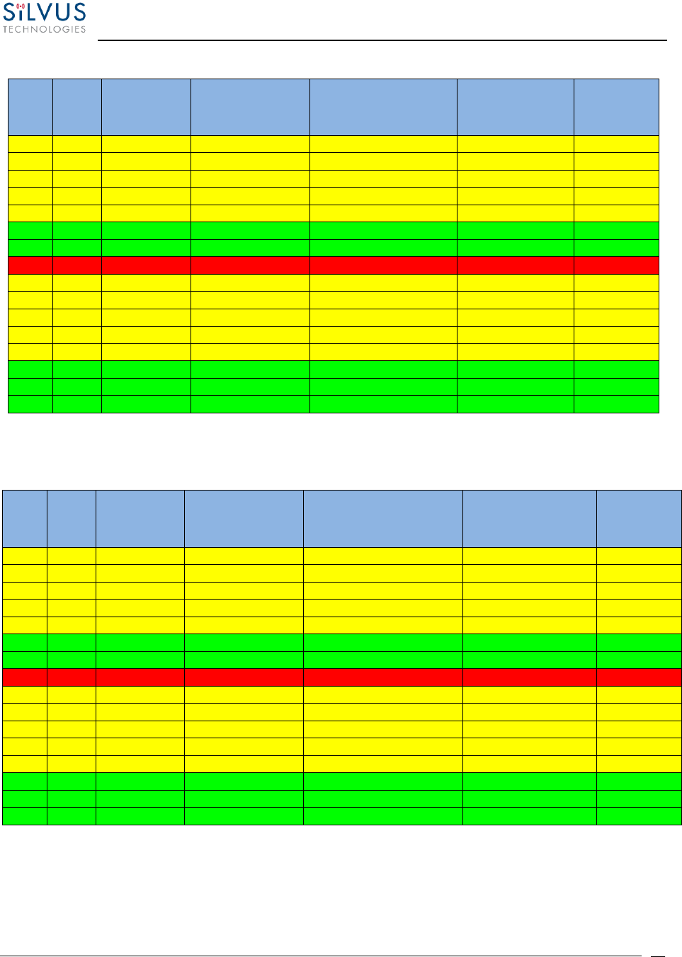
StreamCaster MIMO Radio User Manual 7/24/18
10017C000 Sensitive Company Material – Do Not Duplicate Page
57
NSS
MCS
Coding Rate
PHY Throughput
(Mbps)
UDP User Throughput
(Mbps)
SC4400/3500/3800
Sensitivity
SC4200/3822
Sensitivity
1
0
BPSK 1/2
3.25
2.48
-99
-96
1
1
QPSK 1/2
6.5
4.96
-97
-94
1
2
QPSK 3/4
9.75
7.40
-94
-91
1
3
16-QAM 1/2
13
9.90
-92
-89
1
4
16-QAM 3/4
19.5
14.80
-89
-86
1
5
64 QAM 2/3
26
19.90
-84
-82
1
6
64 QAM 3/4
29.25
22.40
-82
-80
1
7
64 QAM 5/6
32.5
24.0
-77
-78
2
8
BPSK 1/2
6.5
4.96
-97
-94
2
9
QPSK 1/2
13
9.90
-94
-91
2
10
QPSK 3/4
19.5
14.80
-91
-88
2
11
16-QAM 1/2
26
19.90
-89
-86
2
12
16-QAM 3/4
39
29.90
-85
-82
2
13
64 QAM 2/3
52
39.70
-81
-79
2
14
64 QAM 3/4
58.5
43.50
-79
-77
2
15
64 QAM 5/6
65
48.1
-74
-75
Table 19 MCS vs. Sensitivity Chart (10MHz Bandwidth)*
Table 20 MCS vs. Sensitivity Chart (20MHz Bandwidth)*
NSS
MCS
Coding Rate
PHY Throughput
(Mbps)
UDP User Throughput
(Mbps)
SC4400/3500/3800
Sensitivity
SC4200/3822
Sensitivity
1
0
BPSK 1/2
6.5
4.92
-96
-93
1
1
QPSK 1/2
13
9.82
-94
-91
1
2
QPSK 3/4
19.5
14.73
-91
-88
1
3
16-QAM 1/2
26
19.65
-89
-86
1
4
16-QAM 3/4
39
29.47
-86
-83
1
5
64 QAM 2/3
52
39.29
-82
-79
1
6
64 QAM 3/4
58.5
44.20
-80
-77
1
7
64 QAM 5/6
65
47.45
-78
-75
2
8
BPSK 1/2
13
9.82
-94
-91
2
9
QPSK 1/2
26
19.65
-91
-88
2
10
QPSK 3/4
39
29.47
-88
-85
2
11
16-QAM 1/2
52
39.29
-86
-83
2
12
16-QAM 3/4
78
57.04
-82
-79
2
13
64 QAM 2/3
104
75.00
-79
-76
2
14
64 QAM 3/4
117
85.00
-77
-74
2
15
64 QAM 5/6
130
94.00
-75
-72
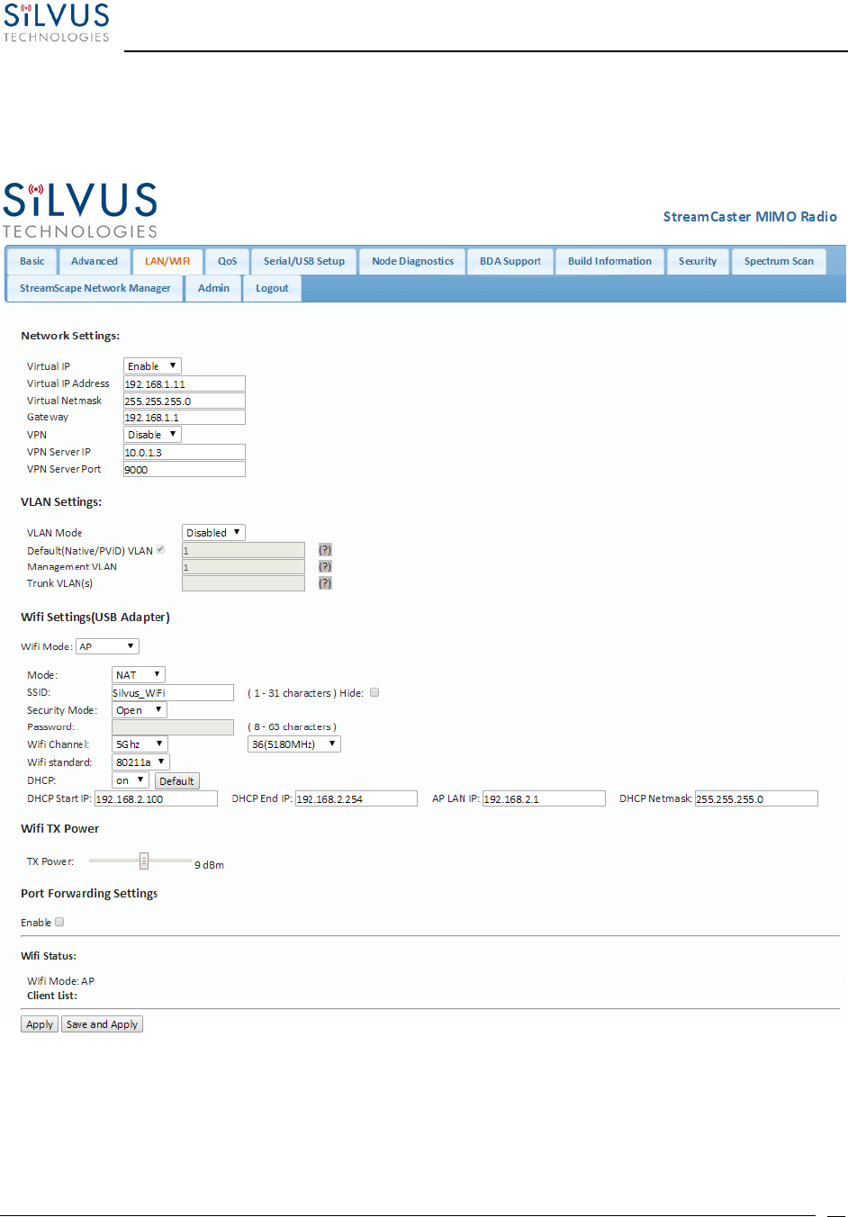
StreamCaster MIMO Radio User Manual 7/24/18
10017C000 Sensitive Company Material – Do Not Duplicate Page
58
*Sensitivity numbers reflect “typical” values. Actual sensitivity will vary by band.
5.1.3 LAN/WIFI Configuration
Figure 25 LAN/WIFI Configuration Page

StreamCaster MIMO Radio User Manual 7/24/18
10017C000 Sensitive Company Material – Do Not Duplicate Page
59
Network Settings:
• Virtual IP: Enable or Disable the Secondary IP address for the radio.
• Virtual IP Address: Set the secondary IP address for the radio. The user may set this to be on the
user’s IP network, e.g., 192.168.2.10. Once this secondary IP address is set, the user may access
the radio web page using either the native IP address or the secondary IP address. Please note
that the secondary IP address should NOT be on the 172.20.xx.xx subnet.
• Virtual Netmask: Netmask for the Secondary IP address, e.g. 255.255.255.0.
• Gateway: Gateway for local network to allow radio to connect to the internet
• VPN: For WAN wired backbone scenarios where radios from two different sites are connected via
the internet, a public N2N server is needed to route the data. Here is an example of how to setup
an N2N server on a server hosted by Amazon AWS running Ubuntu 12.04:
Compile:
git clone https://github.com/lukablurr/n2n_v2_fork ### downloads the code
cd n2n_v2_fork
export N2N_OPTION_AES=no
make clean
make
Execute:
./supernode -l 9000 -v
Server will be running on port 9000.
• VPN Server IP: IP Address of N2N VPN Server
• VPN Server Port: Port that the N2N VPN server is configured to listen on.

StreamCaster MIMO Radio User Manual 7/24/18
10017C000 Sensitive Company Material – Do Not Duplicate Page
60
VLAN Settings (License Enabled Feature):
VLANs allow users to segregate the Ethernet layer by assigning one or more VLAN IDs to the ports of
a VLAN switch. Ethernet packets are only allowed to travel between ports that belong to the same
VLAN. To allow concatenating multiple VLAN switches and/or a single physical interface residing on
multiple VLANs, a VLAN ID can be inserted to the Ethernet packet header to indicate which VLAN the
packet belongs to. This is called VLAN Tagging. A packet that contains a VLAN ID is called a tagged
packet. A port on a VLAN switch typically operates in either access mode or trunk mode.
• VLAN Mode: Specify ‘Access’ or ‘Trunk’ mode for the radio per the 802.1Q standard.
• Default (Native/PVID) VLAN: This is the VLAN associated with untagged packets entering
the radio. The virtual IP of the radio is available on this VLAN.
• Management VLAN: This is the VLAN used for radio management (e.g. routing and
network management). All radios on the network should have the same management
VLAN. The 172.20.xx.yy IP of the radio is available only on this VLAN.
• Trunk VLAN(s): This setting enables the trunking of VLANs when the radio is connected
to an 802.1Q switch. If left empty, only the native and management VLAN traffic will be
allowed. User may enter a comma separated list of VLANS, e.g. 4,5,6 or an arry of VLANs
in the format of a:b:c where a and c are start and end, and b is step size, e.g. 4:1:7
translates to 4,5,6,7. Any combination of the above is allowed.
WiFi Settings (License Enabled Feature – SC3822 Only):
Note: Use of this feature requires a Silvus USB-WiFi adapter. The WiFi settings will only display if
the USB WiFi license is loaded, and the WiFi dongle is attached to the radio’s USB port before it
is powered on.
• Wifi Mode: Choose between AP, Client or Disabled. AP mode turns the WiFi dongle into
a wireless AP. This mode is useful for connecting phones, tablets, laptops, etc. to the radio
in order to pull up the web interface and access other devices in the mesh network. Client
mode allows the radio to connect to another wireless AP. This mode is useful for
connecting to wireless cameras and other devices which generate their own ‘hotspot’.
Once set to client mode, a list of detected wireless networks will be displayed with an
option to connect.

StreamCaster MIMO Radio User Manual 7/24/18
10017C000 Sensitive Company Material – Do Not Duplicate Page
61
• Mode: When set to AP, the wireless can be configured to be in Bridge Mode or NAT mode.
In Bridge mode, the wireless interface is bridged with the Ethernet interface and the rest
of the mesh. This is the simplest mode as all data is transparent and at layer 2. NAT mode
puts the WiFi wireless traffic on a LAN, and the rest of the Silvus mesh network on a WAN.
In effect, this means that a device connected wirelessly via the NAT AP will be able to find
any device in the larger mesh network, but not vice versa. NAT mode is recommended
for more advanced users who wish to be able to segregate data.
• SSID: Define the SSID for the wireless network. Must be between 1-31 characters. User
also has the option to prevent the AP from broadcasting it’s SSID by checking the ‘Hide’
box.
• Security Mode: Determines whether the AP requires a password to connect.
• Password: If ‘Security Mode’ is set to ‘Secure’, a password between 8 and 63 characters
must be set.
• Wifi Channel: The Silvus USB-Wifi adapter supports 20 different Wifi channels in both the
2.4GHz and 5GHz frequency ranges. It is recommended to set the Wifi channel to a
frequency that has maximum separation from the mesh network frequency. (i.e. if mesh
network is operating at 2.4GHz, it is recommended to set the Wifi frequency somewhere
in the 5GHz range). Note that not all user devices support 5GHz Wifi.
• Wifi Standard: Specify 802.11b or g wifi standard. Some legacy devices may not be able
to connect to an 802.11g network.
• DHCP: When enabled, the USB-Wifi adapter will assign IP addresses to connected devices.
Note that when the AP is set to ‘Bridge’ mode, the DHCP will be delivered to the entire
mesh. Users should be careful to make sure there is only one DHCP server connected into
the mesh network to avoid any conflicts. When DHCP is enabled, the DHCP parameters
must be set.
• Wifi TX Power: This slider can be used to control the Wifi TX power from 0dBm (1mW) up
to 17dBm (50mW).
• Wifi Status: Provides status information of the wifi adapter. A list of connected clients will
also be shown here.
• Port Forwarding (NAT Mode Only): When in NAT mode, devices on the larger mesh will
not be able to locate devices connected to the wireless adapter. This can be overcome by
mapping port forwarding for specific data streams.
• Apply: Applies the new values but does not save them to flash.
• Save and Apply: Save the new values to flash and apply.

StreamCaster MIMO Radio User Manual 7/24/18
10017C000 Sensitive Company Material – Do Not Duplicate Page
62
5.1.4 Multicast
Figure 26 Multicast Configuration Page
• IGMP Snooping: Enable or Disable IGMP Snooping for Multicast traffic
• Mesh: This option controls default behavior for local and mesh multicast traffic that has no IGMP
snooping entries. If set to ‘Block’, all unregistered multicast traffic will be block. If set to ‘Send to
All’, all unregistered multicast traffic will be sent to all radios.
• Custom Pruning/Augmenting: Enable or Disable the Multicast group. The format for the field is
Multicast_ip_address, receiver_id1, … receiver_idn If IGMP snooping is disabled, multicast traffic
will only be forwarded to the radios in this list. If enabled, multicast traffic will only be forwarded
to radios in this list that have client devices requesting this traffic. Traffic may be forced to go to
a radio by adding the node with postfix “+”. Traffic may be prevented from reaching a radio by
adding postfix “-”. (e.g. 224.50.50.50 1234, 1235-, 1236+) If receiver_id is -1, it will stop multicast
traffic for this group.
Multicast Pruning Examples:
Data for multicast group 224.50.50.51 will be received only by radios with node-ids 1131 and
1261:
224.50.50.51, 1131, 1261
Data for multicast group 224.50.50.51 will be discarded at the transmitter and not put on the air:
224.50.50.51, -1
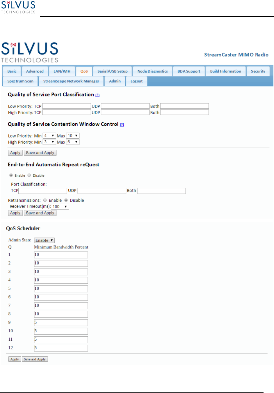
StreamCaster MIMO Radio User Manual 7/24/18
10017C000 Sensitive Company Material – Do Not Duplicate Page
63
5.1.5 Quality of Service (QoS) #QoS
Figure 27 Quality of Service (QoS) Configuration Page

StreamCaster MIMO Radio User Manual 7/24/18
10017C000 Sensitive Company Material – Do Not Duplicate Page
64
Quality of Service Port Classification:
The Quality of Service configuration page allows the user to make a distinction between low and
high priority traffic transmitted through each radio. High priority traffic will always jump to the
front of the queue and bypass any awaiting low priority traffic. In instances where the link cannot
support the amount of data trying to be transmitted, low priority traffic may be completely
shelved in order to ensure that the high priority traffic gets through.
To specify Low/High priority traffic, the user needs to simply input the port number that the
traffic will be arriving on. Multiple ports of the same priority can be separated by a comma (i.e.
5001, 6001, 6002). Alternatively, the user can specify a range of ports using a dash (i.e. 5001-
5006). Any combination of commas and dashes will work as well (i.e. 5001, 6001-6007, 8000).
Any field can be cleared by removing the text and clicking ‘Apply’ or ‘Save and Apply’. If
unspecified, traffic is treated as Low Priority.
Quality of Service Contention Window Control:
The Quality of Service Contention Window Control tunes the aggressiveness of CSMA backoffs
when collisions occur. The MAC takes random backoffs in the range [0, 2^cw_min]. Every time
there is a collision/noise it will increase this cw_min by 1, until it is capped by cw_max.
E.g. 4,10 translates to random backoffs in the range [0,16] in the beginning for a packet. If the
first try results in a collision, it will pick another backoff in the range [0,32], then [0,64], until
[0,1024]. After successful transmission, backoff is reset to [0,16]. The default is 4,10 for low
priority, and 3,6 for high priority. For larger networks, it is recommended to increase the Low
Priority minimum to reduce the chance of collisions occurring.
End-to-End Automatic Repeat request (Beta Feature – License Enabled)
The End-to-End ARQ feature provides packet re-ordering capability to the radio. This feature is
useful in applications that are sensitive to out of order packets (i.e. video applications where the
decoder does not have the ability to re-order packets).
To enable packet reordering, specify the port number of the subject data in the same format as
the QoS ports on the source and destination radio. The settings should match on both radios and
do not need to be set on any relays.
Retransmissions Disabled – Only packet re-ordering with no end-to-end retransmissions if
packets are lost. The receiver timeout is the length of time the receiver waits for out-of-order
packets before giving up and delivering the data it has in its buffer. This is similar in concept to

StreamCaster MIMO Radio User Manual 7/24/18
10017C000 Sensitive Company Material – Do Not Duplicate Page
65
the jitter buffer in common video decoders (e.g. VLC). The worst case end-to-end delay will be
incremented by the receiver timeout value.
Retransmissions Enabled – Packet re-ordering and end-to-end retransmissions enabled in case
of packet loss. The retransmission timeout is the time the transmitter will wait before re-sending
a lost packet. The worst case end-to-end delay will be incremented by the retransmission timeout
value.
Determining Timeout Value – Both receiver timeout and retransmission timeout should be set
to roughly 3 times the end-to-end latency. The end-to-end latency can be found by disabling e2e
and doing a ping between the transmitter and receiver.
QoS Scheduler (Beta Feature – License Enabled)
The Quality of Service (QoS) Scheduler feature provides a Hierarchical Token Bucket (HTB)
scheduler. The scheduler prioritizes traffic based on the packets DSCP value. There are 12 queues
in the scheduler; each with an assignable minimum bandwidth guarantee. First, the minimum
guarantees are fulfilled for all queues waiting to transmit traffic out. If there is bandwidth
remaining, it becomes available to highest priority traffic (lower number means higher priority)
and it will take as much bandwidth as it needs to transmit out its data. Next, the remaining
bandwidth will become available to the next lowest priority queue and so on. Traffic flows which
map to the same priority will fairly share the available bandwidth using the Fair Queuing with
Control Delay (FQ_CoDeL) scheduling algorithm. The feature is applicable to IPv4 and IPv6
untagged and tagged packets. Fragmented packets are not supported. Detailed below is the DSCP
to queue/priority mapping.
Queue
Priority
DSCP
TOS
DSCP
Name
1
0
0x30
0xC0
CS6
2
1
0x2E
0xB8
EF
3
2
0x28
0xA0
CS5
4
3
0x26
0x98
AF43
0x24
0x90
AF42
0x22
0x88
AF41
5
3
0x20
0x80
CS4
6
4
0x1E
0x78
AF33
0x1C
0x70
AF32

StreamCaster MIMO Radio User Manual 7/24/18
10017C000 Sensitive Company Material – Do Not Duplicate Page
66
0x1A
0x68
AF31
7
4
0x18
0x60
CS3
8
5
0x16
0x58
AF23
0x14
0x50
AF23
0x12
0x48
AF23
9
5
0x10
0x40
CS2
10
6
0x0E
0x38
AF13
0x0C
0x30
AF12
0x0A
0x28
AF11
11
6
0x00
0x00
BE
12
7
0x08
0x20
CS1
Admin State – Enables and disables the scheduler.
Minimum Bandwidth Percent – Sets the minimum bandwidth guarantee for the queues as a
percentage of the link rate. The sum of the minimum bandwidth guarantees cannot exceed 100%
of the link rate.
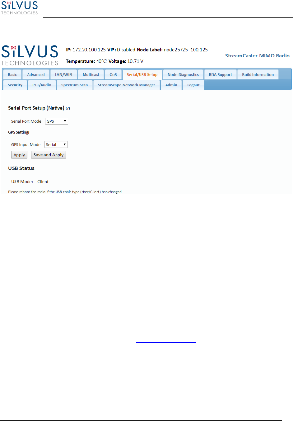
StreamCaster MIMO Radio User Manual 7/24/18
10017C000 Sensitive Company Material – Do Not Duplicate Page
67
5.1.6 Serial/USB Setup
Figure 28 Serial/USB Setup Configuration Page
Serial Port Setup:
Each StreamCaster is equipped with one user configurable serial port. A special power cable and
null modem cable are required for access to the radio’s serial port. A brief description of each
parameter is given below.
• Serial Port Mode: The user can select one of four available modes for the serial port: GPS, RS232,
Debug, and Disabled.
o GPS: In GPS mode, an external serial GPS module can be connected to and powered from
the serial port of the radio. A gpsd service daemon running on the node will make the GPS
information available to any user on the network from TCP/IP port 2947. For more
information on gpsd please see: http://catb.org/gpsd/
In addition, GPS information can be pushed to the radio via the Ethernet port or pulled
by the radio from a remote device such as an SC-IOM. If using an SC-IOM to obtain GPS,
set the GPS mode to remote, the GPS Server IP to the IP address of the SC-IOM, and the
Port to 2947.

StreamCaster MIMO Radio User Manual 7/24/18
10017C000 Sensitive Company Material – Do Not Duplicate Page
68
o RS-232: The RS-232 mode provides a wireless serial connection between any two serial
devices connected to StreamCaster radios on the network. In this mode, the user must
configure the RS-232 protocol parameters shown in Figure 28 above. The transport
protocol for the serial data can be set as either TCP or UDP. For data that is sensitive to
latency such as command and control data, UDP is recommended. For data that cannot
tolerate any data loss, such as telemetry data, TCP is recommended.
▪ The Peer IP should be the IP address of the radio on the other end of the RS-232
communication.
▪ The Peer IP can be the native or virtual IP address, but must be consistent at both
ends.
▪ Baud rate must match the baud rate of data being sent from the device.
▪ Note – An additional ‘null modem’ cable may be needed at either end, depending
upon whether connected device is acting as a terminal or as a control (DTE or
DCE)
o Debug: The debug mode is used to gain terminal access to the StreamCaster radio and is
available for debug or interface purposes (API commands). The user’s terminal client
should be set to a baud rate of 115200 for console access to the radio.
o Disabled: This mode completely disables the serial terminal of the radio.
• Apply: Apply the new values but does not save them to flash.
• Save and Apply: Save the new values to flash and apply.
USB Status (3822/4200/4400):
The USB port on the 3822/4200/4400 can auto-detect whether the connected device is a USB
host or client device. The USB cable should not be unplugged while the radio is running.
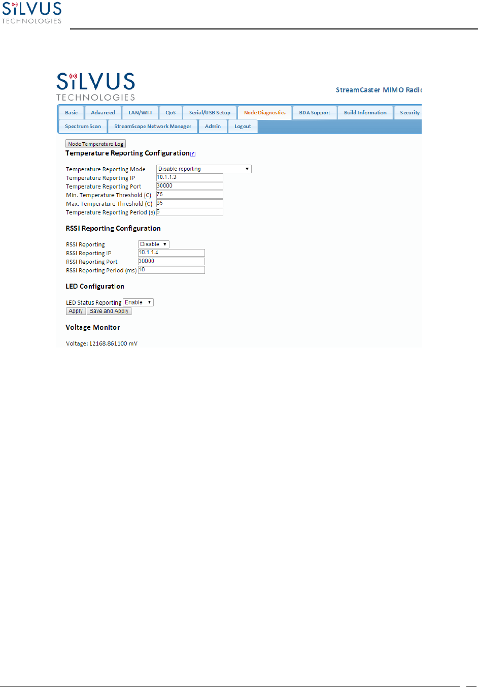
StreamCaster MIMO Radio User Manual 7/24/18
10017C000 Sensitive Company Material – Do Not Duplicate Page
69
5.1.7 Node Diagnostics
Figure 29 Node Diagnostics Configuration Page
The Node Diagnostics page allows the user to specify an IP and Port number for Temperature and
RSSI (Receiver Signal Strength Indication) reports to be delivered to. This is useful for users that
intend to feed this information into some other platform for analysis and recording. Section 8
gives more information on the format of streaming reports.
Temperature Thresholds:
In addition to receiving temperature reports, this page can be used to set minimum and
maximum temperature thresholds for the radio. The StreamCaster™ family of radios is equipped
with on board temperature sensors which are monitored to prevent overheating. Once a radio
reaches the maximum temperature threshold, the radio will begin to reduce its transmission time
until the temperature falls below the minimum temperature threshold. By default, the min and
max values are 75C and 85C respectively.
RSSI Reporting Configuration
This setting allows the users to report the RSSI values every few milliseconds base on users
setting.
LED Configuration:
This setting allows the user to disable or enable the LED on the faceplate of the radio.

StreamCaster MIMO Radio User Manual 7/24/18
10017C000 Sensitive Company Material – Do Not Duplicate Page
70
Voltage Monitor:
Radios built on or after Jan 1, 2015 have the ability to monitor the input voltage, displayed here.
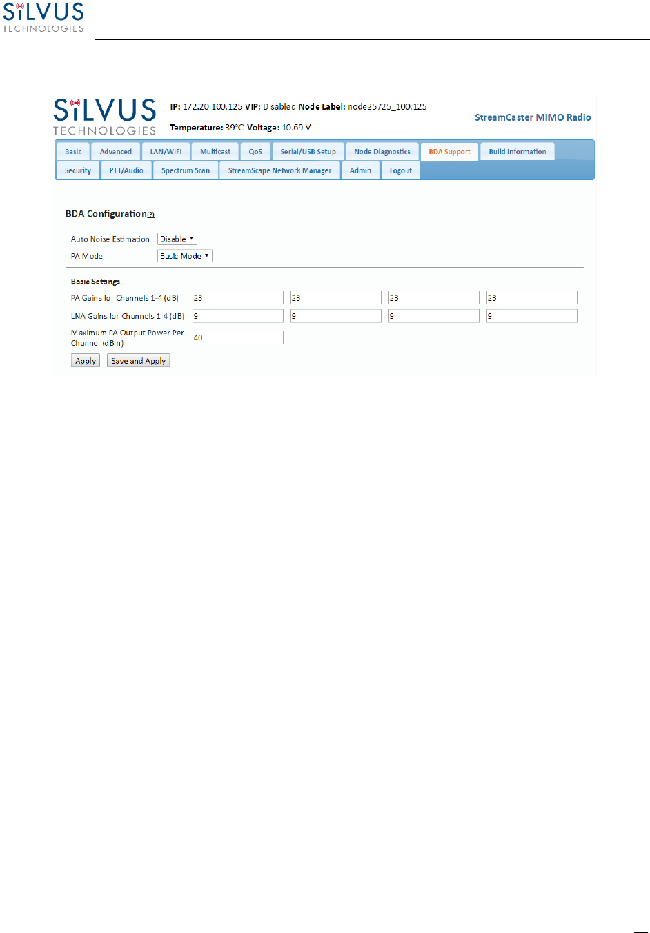
StreamCaster MIMO Radio User Manual 7/24/18
10017C000 Sensitive Company Material – Do Not Duplicate Page
71
5.1.8 BDA Support
Figure 30 BDA (Bi-Directional Amplifier) Support Configuration Page
The BDA Support page is used to configure the radio to work with an external bi-directional
amplifier. These settings should be configured before connecting the amplifier to the radio.
• Auto Noise Estimation: When enabled, the radio can automatically estimate the noise in
the channel, including any amplification due to the external amplifier. It is preferred that
this remain disabled and the LNA gain values be manually input further below, but if the
LNA gain values are not known, this can be used instead.
• PA Mode: Either set to “No PA” when there is no amplifier present or “Basic Mode” when
using an external amplifier.
Basic Settings:
• PA Gains for Channels 1-4: Enter the gain (dB) for the power amplifier connected to each
channel of the radio.
• LNA Gains for Channels 1-4: Enter the gain (dB) for the LNA connected to each channel
of the radio.
• Maximum PA Output Power Per Channel (dBm): Enter the maximum output power for
each PA.
• Apply: Apply the new values but does not save them to flash.
• Save and Apply: Save the new values to flash and apply.

StreamCaster MIMO Radio User Manual 7/24/18
10017C000 Sensitive Company Material – Do Not Duplicate Page
72
5.1.9 Build Information
Figure 31 Build Information
The ‘Build Information’ page provides information about the hardware and firmware loaded onto
the radio, as well as the changelog of the currently loaded and past firmware revisions.
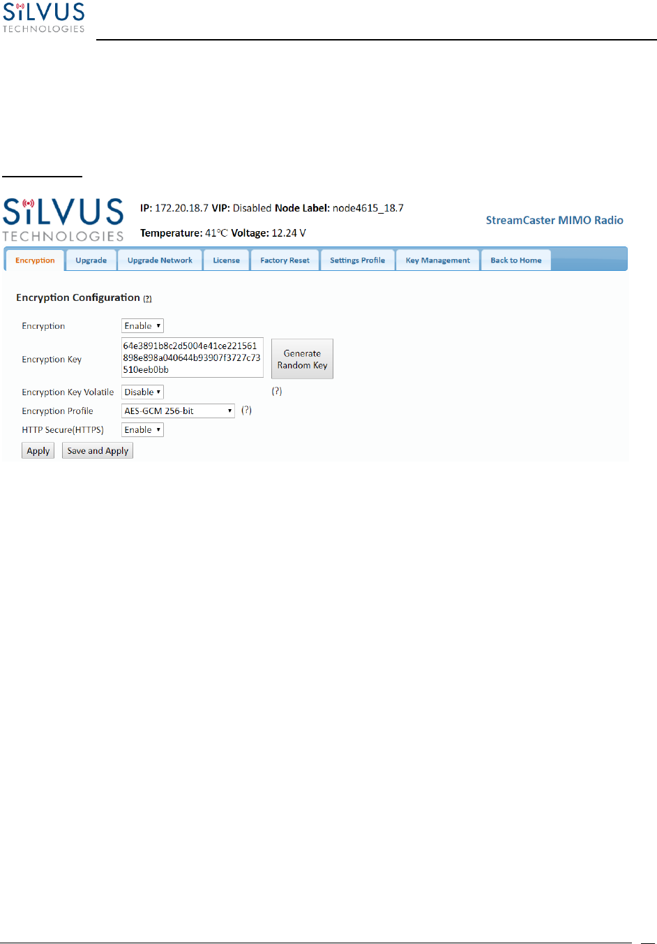
StreamCaster MIMO Radio User Manual 7/24/18
10017C000 Sensitive Company Material – Do Not Duplicate Page
73
5.1.10 Security
The Security section of StreamScape allows users to enable/disable encryption, upgrade radios,
and load license files for enabling features such as AES encryption.
Encryption:
Figure 32 Security (Encryption)
• Encryption: Enable or disable encryption.
• FIPS Mode: Enabling FIPS mode is the first step to making the radio FIPS compliant (see Section
6.1 Enable FIPS Mode for details). Enabling/disabling will require a reboot and will erase all setting
profiles, reset the encryption key, both SSH keys, the HTTPS certificate, and the login passwords
to their factory default. Enabling will also turn on HTTPS and Login Authentication. After reboot,
the operator must perform the following steps to complete the FIPS compliant process.
o Update the web login password to something other than “HelloWorld”
o Create new SSH keys and HTTPS certificate.
o Update encryption key or click “Generate Encryption Key” and save.
• Encryption Key: Set an encryption key if encryption is enabled.
• Encryption Profile: Choose between various encryption profiles. Available options are:
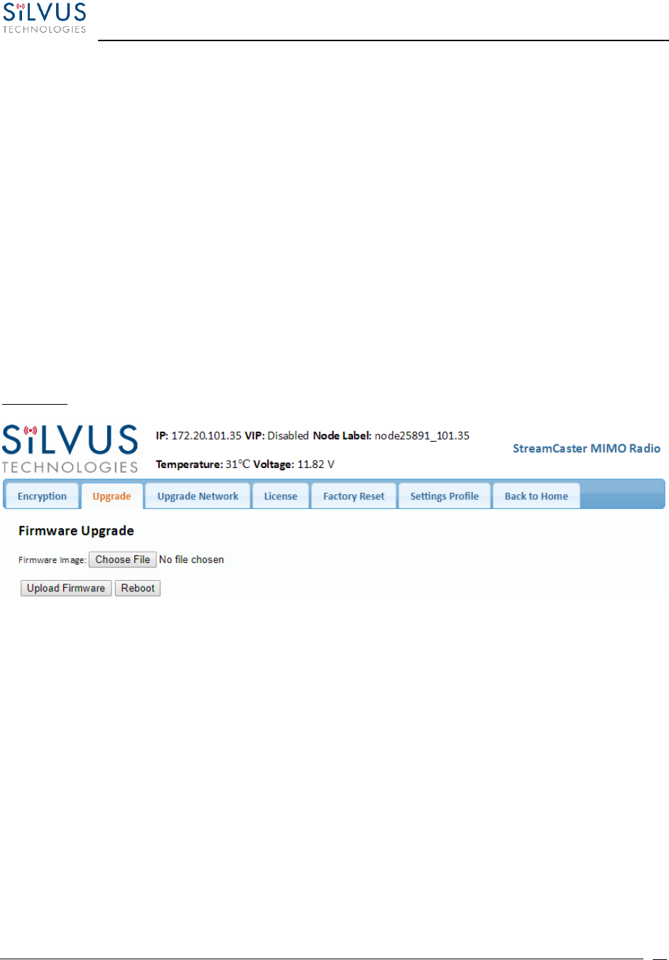
StreamCaster MIMO Radio User Manual 7/24/18
10017C000 Sensitive Company Material – Do Not Duplicate Page
74
o DES 56 bit – DES encryption using 56 bit keys. This mode is backwards compatible with
legacy SC3500/3800 radios.
o AES 128/256 – AES encryption using 128/256 bit keys. This mode is backwards compatible
with legacy SC3500/3800 radios.
o AES-GCM 256 ECDH-KAS – FIPS compliant AES encryption in GCM mode with
authentication and ECDHE based re-keying. This is the recommended mode on the 4K
series as it is the most secure and provides the highest throughput under varied
conditions. It is currently undergoing FIPS certification for the 4K series.
• HTTP Secure (HTTPS): Enable or disable HTTPS access to StreamScape.
Upgrade:
Figure 33 Security (Upgrade)
The firmware can be upgraded by simply choosing the upgrade image from your desktop and
uploading it to the radio. This field can be used to upgrade the radio root file system, linux kernel,
or uboot.
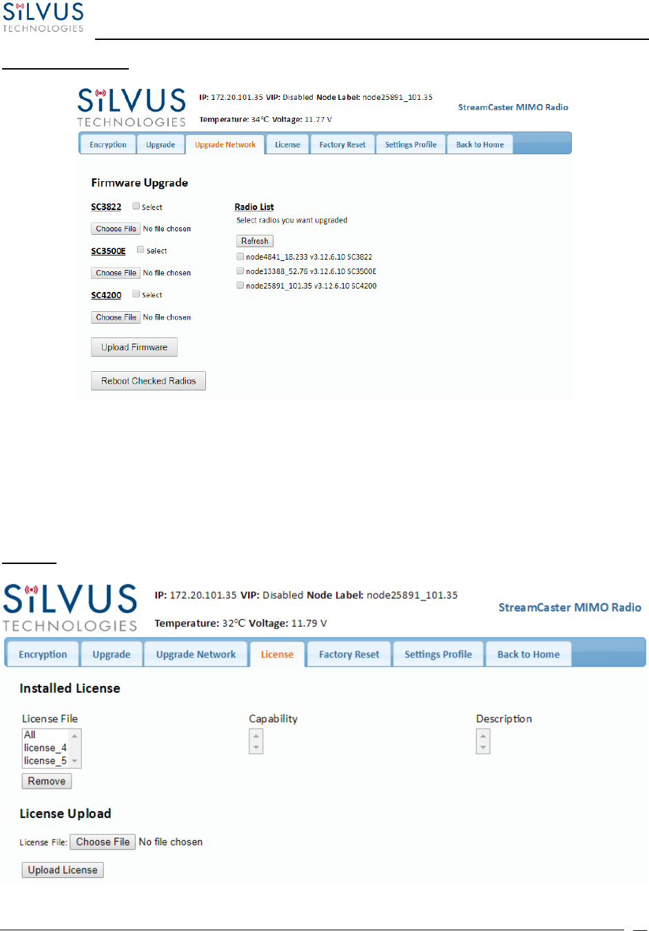
StreamCaster MIMO Radio User Manual 7/24/18
10017C000 Sensitive Company Material – Do Not Duplicate Page
75
Upgrade Network:
Figure 34 Security (Upgrade Network)
Starting with firmware version 3.12.6.8, multiple radios within the same network can be
upgraded all at once. Users can simply choose the appropriate firmware file for the
corresponding radio models to apply the upgrade to all the radios in the network. Currently, this
feature is not available in HTTPS mode.
License:
Figure 35 Security (License)

StreamCaster MIMO Radio User Manual 7/24/18
10017C000 Sensitive Company Material – Do Not Duplicate Page
76
Features such as encryption levels and frequency ranges can be enabled by license keys obtained
from Silvus. New license keys can be uploaded to the radio on this page.
Factory Reset:
Figure 36 Security (Factory Reset)
• Restore Factory Default: Restores all settings to default except those related to security
(such as login passwords, encryption keys, FIPS mode, etc.). This is useful if the user
changed some advanced settings and now they don’t know how to get to the defaults.
• Zeroize Security: This will set login passwords and all security keys to their defaults. This
includes the Encryption Key, SSH Login Key, SSH Host Key, HTTPS Certificate, and
Encryption Key Volatile. It will also erase all settings profiles. Also, if FIPS mode is off, it
will turn off HTTPS and login mode. The current FIPS mode will not be changed.
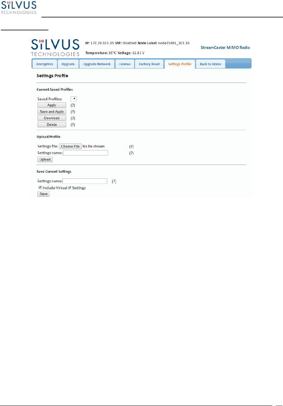
StreamCaster MIMO Radio User Manual 7/24/18
10017C000 Sensitive Company Material – Do Not Duplicate Page
77
Settings profile:
Figure 37 Security (Setting Profile)
• Current Saved Profiles: Select a saved profile and apply the settings to use the selected
profile. The profile stored can be downloaded or deleted.
• Upload Profile: Select a downloaded profile from the computer and upload to the radio
as a saved profile.
• Save Current Settings: Store the current settings on to the radio for future access. Note
that the FIPS mode setting is not saved in the profile. You must manually enable/disable
it after applying the profile.

StreamCaster MIMO Radio User Manual 7/24/18
10017C000 Sensitive Company Material – Do Not Duplicate Page
78
Key Management:
Figure 38 (Key Management)
This page is used to manage the radio’s SSH login keys, SSH host key, and HTTPS Certificate. All
key pairs used are elliptic curves.
• SSH Login Keys: In order to SSH into the radio, you must first generate a key pair and
upload the public key onto the radio. A common way this is done on a computer is through
the command `ssh-keygen -t ecdsa -b 521`. You will need to do this for each machine that
wants to SSH into the radio, or you can share a single key pair amongst machines.
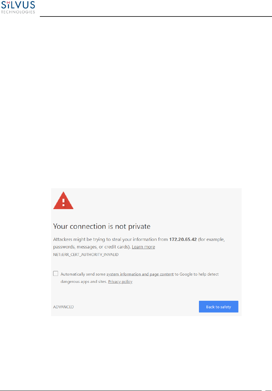
StreamCaster MIMO Radio User Manual 7/24/18
10017C000 Sensitive Company Material – Do Not Duplicate Page
79
• SSH Host Key: This key is used for authenticating the radio to all machines that want to
connect to it via SSH. A common way this key is generated on a computer is ‘openssl
ecparam -name secp521r -genkey -noout -out yourfilename`. You may either upload your
own key or generate one on the radio. Once you upload/generate a new key, the previous
one is gone. You can get the original key by Factory Reset -> Zeroize. (Note that the
generated text from the above command will encode both a private and public key in the
text).
• HTTPS Certificate: This certificate is used to establish a HTTPS connection. If you are using
a factory default or radio generated certificate and haven’t added an exception of this
certificate to your browser, you will see a message like below from your browser. This is
because the certificate is signed by the radio and not a trusted Certificate Authority. You
can bypass this by clicking “ADVANCED” in chrome, (or adding an exception in Firefox).
The simplest way to generate a new certificate is to click “Generate Certificate and Save”
button. If you are on HTTPS when you do this, you must also refresh the page. If you want
to generate your own certificate, you must first generate a key pair (secp256r1,
secp384r1, or secp521r1). Then create a X.509 certificate and append your private key to
it. Copy the certificate text to the “Add a HTTPS Certificate” section, then click “Add
Certificate and Save.”
Figure 39 (Chrome Browser Warning)
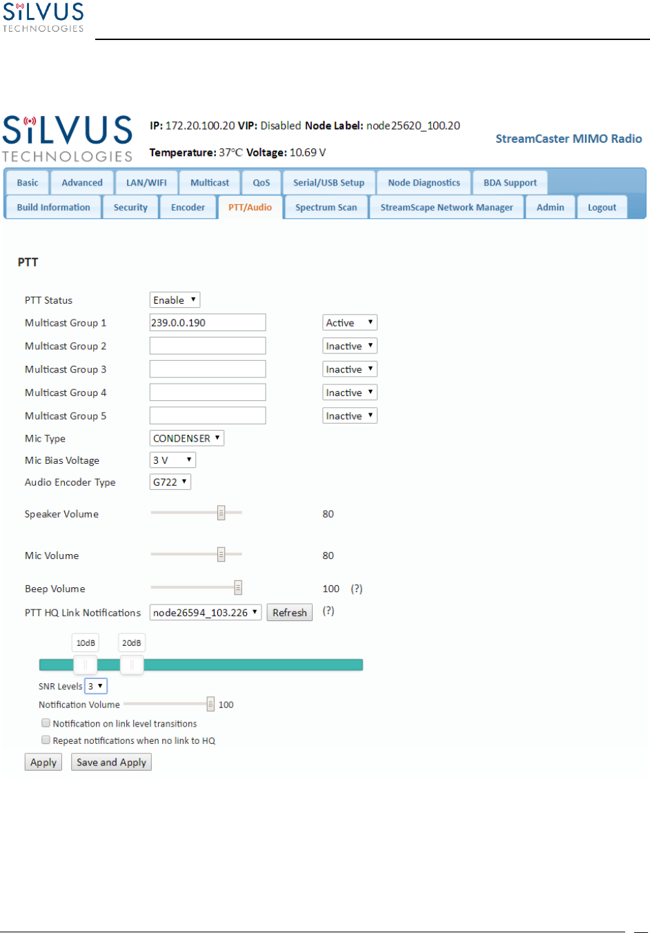
StreamCaster MIMO Radio User Manual 7/24/18
10017C000 Sensitive Company Material – Do Not Duplicate Page
80
5.1.11 PTT (SC4400/SC4200 Only)
Figure 40 PTT (Push-to-Talk)
The PTT page can be used to configure talk groups (Multicast Groups) and speaker/mic settings
for PTT enabled radios. Radios will only communicate with other radios that are subscribed to
the same ‘Multicast Group’. Radios can be active in multiple talk groups.

StreamCaster MIMO Radio User Manual 7/24/18
10017C000 Sensitive Company Material – Do Not Duplicate Page
81
Multicast Group – Input the IP address of the multicast group. Radios will only communicate to
radios within the same group. There are three different modes to select which dictate how a
radio behaves within a group:
• Active: Radio may send and receive PTT audio on this group.
• Inactive: Group is disabled, no PTT audio will be sent or received.
• Monitor: Radio may listen to PTT audio from other users on this group, but may
not talk.
Mic Type – Supported MIC types are Moving Coil or Condenser. The input amplification is
adjusted based on the Mic Type chosen on this page
Mic Bias Voltage – Options are 90% (3V) or 65% (2.15V).
Audio Encoder Type – Default option is G.722 (high quality). G.711 is also supported for
backwards compatibility with the SC-IOM
Speaker Volume – Moving slider adjusts the gain on the speaker
Mic Volume – Moving slider adjusts the gain on the microphone
Beep Volume + PTT Override – When the PTT button is pressed while another user is speaking,
a warning beep will be played. This setting controls the volume of the Beep as a percent (%) of
the speaker volume above. Pressing the PTT button three times (and holding on the third) within
1s will allow a user to override the channel and speak.
PTT HQ Link Notifications – When the PTT button is pressed twice within 1s, an audio notification
will read out the SNR level to the user-specified HQ node. If the level transitions option is enabled,
the notification will be played automatically when the SNR crosses the specified thresholds. The
SNR thresholds can be set by first choosing the number of levels desired, and then moving the
sliders accordingly.
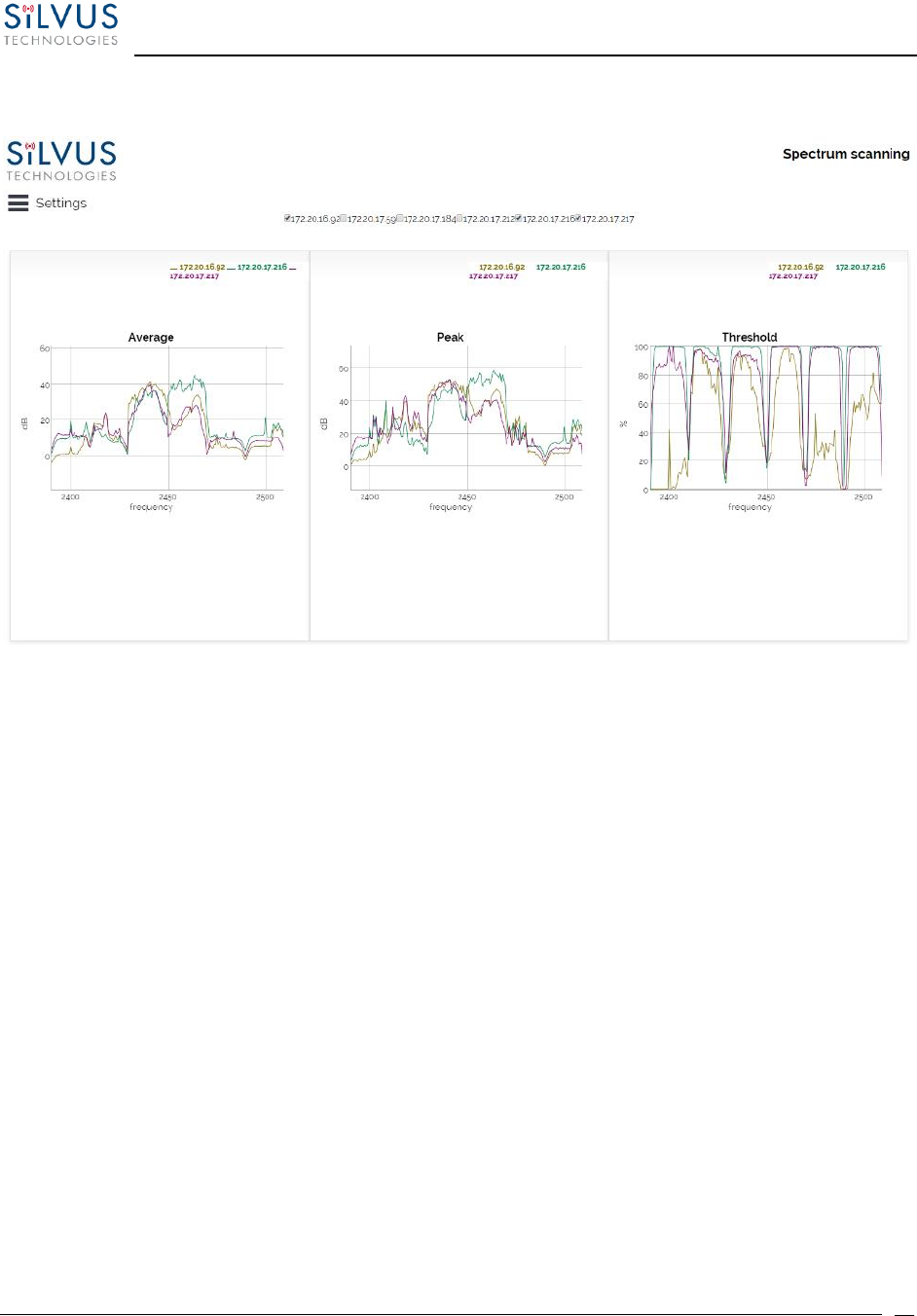
StreamCaster MIMO Radio User Manual 7/24/18
10017C000 Sensitive Company Material – Do Not Duplicate Page
82
5.1.12 Spectrum Scan
Figure 41 Spectrum Scan Results
The spectrum scan feature turns a Silvus network of radios into a distributed spectrum analyzer.
When a scan is initiated, each selected radio in the network will go offline, perform a scan of the
requested range, and report back. Figure 41 Spectrum Scan above shows the results from a scan of
a network of 6 radios. The checkboxes at the top allow users to show or hide plots from specific
radios. The three plots provided are:
Average – Displays the average power over the time duration specified in the settings.
Peak – Displays the peak power seen at any point during the scan for each frequency. This is the
equivalent of the ‘Max Hold’ feature on common spectrum analyzers.
Threshold – Displays the duty cycle of interference stronger than the user specified ‘Threshold’
power. In the example above, the threshold was set to 5dB. The plot is showing the percentage
of time that the measured power is more than 5dB above the radio’s noise floor.
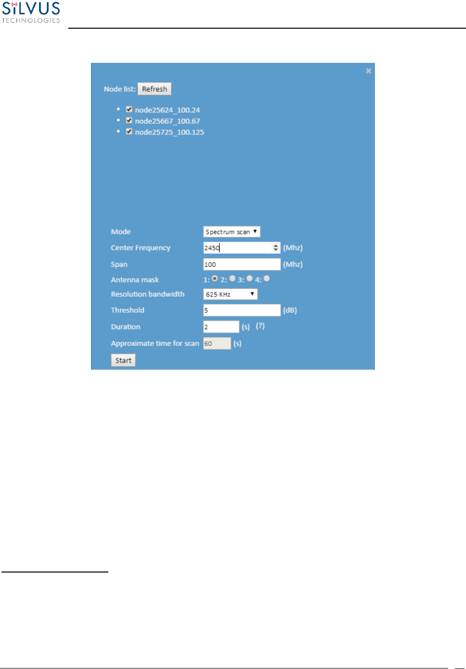
StreamCaster MIMO Radio User Manual 7/24/18
10017C000 Sensitive Company Material – Do Not Duplicate Page
83
Settings:
Figure 42 Spectrum Scan Settings
Clicking the settings button at the top left of the window will show the settings pane as shown in
Figure 42 Spectrum Scan Settings The node list shows the list of nodes currently connected into the
mesh network. Any nodes selected will be used as part of the spectrum scan. Nodes that are
unchecked will resume normal operation. Note that an unchecked node will continue
transmitting in the frequency channel it is operating in and its transmission will show up in the
scan results of scanning radios.
Mode – Set to Spectrum Scan or Zero Span. Spectrum Scan mode provides plots of signal strength
over frequency. Zero Span provides a plot of power over time in a 20MHz Bandwidth (see Figure
44 Zero Span Results below.
Spectrum Scan Mode:
Center Frequency – Specify the center frequency of the scan.
Span – Specify the span of the scan, centered on the center frequency. (e.g. Center freq
of 2450MHz and span of 100MHz will scan 2400-2500MHz). A large span will take longer
to complete.

StreamCaster MIMO Radio User Manual 7/24/18
10017C000 Sensitive Company Material – Do Not Duplicate Page
84
Antenna Mask – Choose which antenna on the radio to use for scanning. If there are 2
antenna radios in the network antenna 1 or 2 must be chosen.
Resolution Bandwidth – Specify the RBW for the scan. A smaller RBW will provide a more
detailed plot, but will take longer to complete the scan. 625KHz is a good balance between
scan detail and time of scan.
Threshold – Specify the threshold for measurement of the duty cycle of interference.
Duration – Duration of each scan. A longer duration will provide better accuracy but will
take longer to complete.
Approximate time for scan – Approximate time that the network will be down for the
scan to complete.
Zero Span Mode:
Figure 43 Zero Span Settings
In the Zero Span mode, the radio will provide a plot of the power measured in a 20MHz
bandwidth across time. Zero Span can only be conducted on one radio in the network at
a time. Other radios in the network will continue to operate and transmit so a zero span
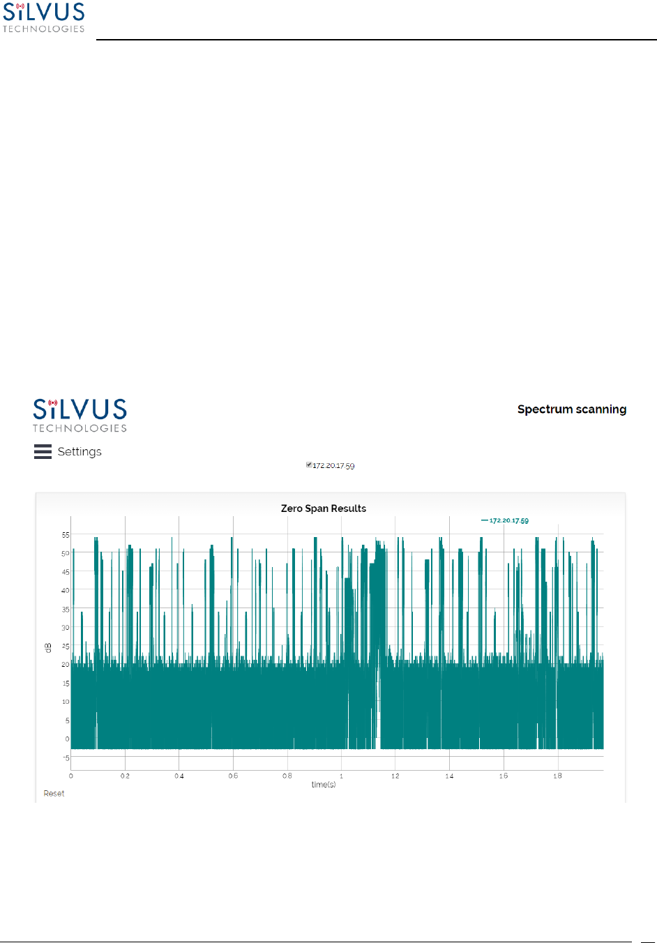
StreamCaster MIMO Radio User Manual 7/24/18
10017C000 Sensitive Company Material – Do Not Duplicate Page
85
scan should not be conducted within the same frequency that the mesh network is
operating in.
Center Frequency – Specify the center frequency of the scan.
Sampling Rate – Set the sampling rate of the scan. (0.3Msps recommended)
Antenna Mask – Choose which antenna on the radio to use for scanning. If there are 2
antenna radios in the network antenna 1 or 2 must be chosen.
Duration – Duration of each scan. A longer duration will provide better accuracy but will
take longer to complete.
Approximated time for scan – Approximate time that the network will be down for the
scan to complete.
Figure 44 Zero Span Results
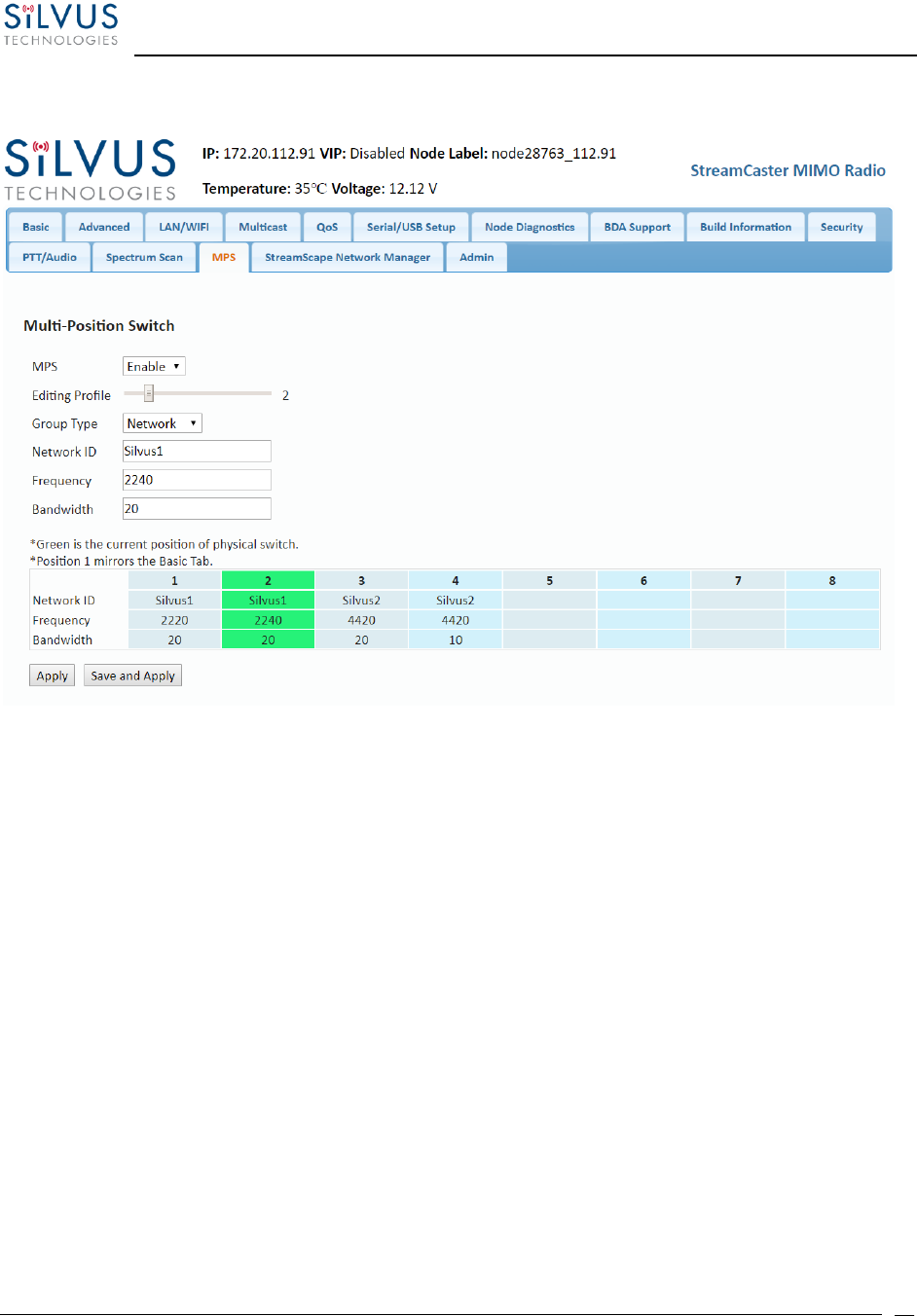
StreamCaster MIMO Radio User Manual 7/24/18
10017C000 Sensitive Company Material – Do Not Duplicate Page
86
5.1.13 MPS (Multi-Position Switch)
Figure 45 Multi-Position Switch
The Multi-Position Switch allows you to change various settings of the radio by using the new
physical switch, no web GUI required (This is not available on all radios).
You must first configure the settings you want to correspond with each switch position. The
“Editing Profile” slider represents which position is currently being edited. “Group Type”
represents the collection of settings that will be applied. Only one “Group Type” is active at a
given time. When the MPS switch is turned, the LED light on the radio will quickly flash green.
This means the settings are being applied for this position. When the LED stops quickly flashing,
the settings have been applied.
Position 1 is special. Any time settings are updated from the GUI without using the MPS page (i.e.
Basic Tab, PTT/Audio Tab), position 1 will be updated with those results. The green highlight
shows the current position of the physical switch.
If the radio boots up in position “Z,” MPS will be disabled until the radio is rebooted in another
position.
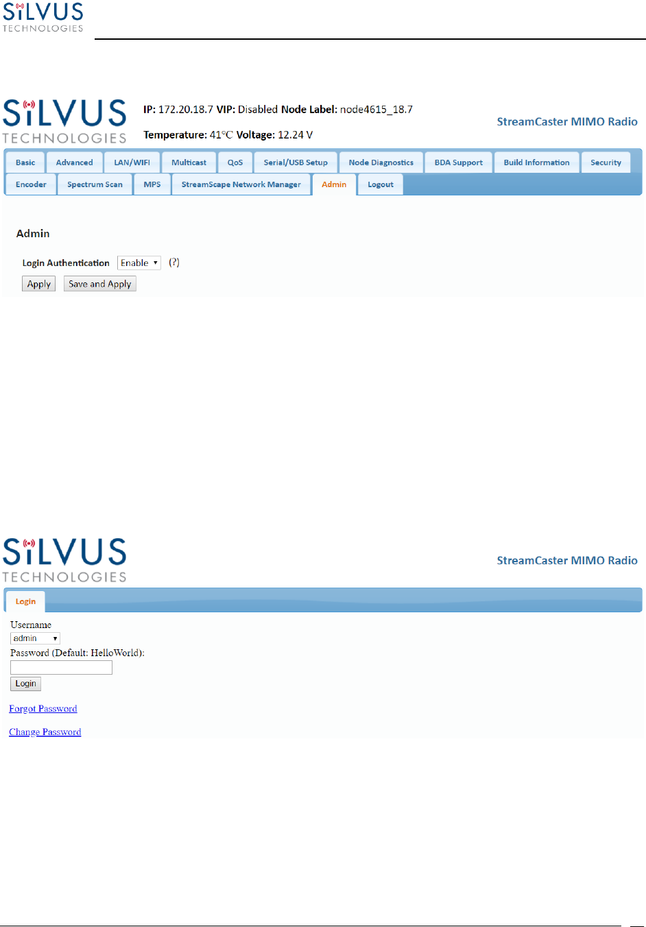
StreamCaster MIMO Radio User Manual 7/24/18
10017C000 Sensitive Company Material – Do Not Duplicate Page
87
5.1.14 Admin Settings
Figure 46 Admin Settings
The Admin Settings page provides the option of password protecting access to Streamscape.
There are three usernames, Basic, Advanced, and Admin, each with increasing privileges on the
GUI and backend API. For example, only Admin can access the Security tab. To enable, set the
Login Authentication to Enable and provide a password. Once Login Authentication is enabled,
access to Streamscape will require a username and password as shown below. To change the
password, click “Change Password,” then select the username whose password will change, type
the Admin password, then type the new password.
Figure 47 Login

StreamCaster MIMO Radio User Manual 7/24/18
10017C000 Sensitive Company Material – Do Not Duplicate Page
88
Reset Password:
Figure 48 Reset Password
If a user forgets the password, click “Forgot Password.” They can reset the password using a USB
flash drive and a password reset key provided by Silvus. On the USB, the password reset key file
must be called reset_pass.txt.signed. Note that since the SC3500 and SC3800 do not have USB
ports, you will not be able to set a password for these radios.
This will set login passwords and all security keys to their defaults. This includes the Encryption
Key, SSH Login Key, SSH Host Key, HTTPS Certificate, and Encryption Key Volatile. It will also erase
all settings profiles. Also, if FIPS mode is off, it will turn off HTTPS and login mode. The current
FIPS mode will not be changed.
StreamCaster MIMO Radio User Manual 7/24/18
10017C000 Sensitive Company Material – Do Not Duplicate Page
89
5.2 StreamScape Network Manager
Silvus’ StreamScape Network Management Utility was designed to monitor the status of a Silvus mesh
network in real-time. The graphical interface network map, shown in Figure 44, allows users to quickly
and effortlessly view the network topology and configure key parameters of the network. For ease of use,
the Silvus StreamScape utility is designed to be accessible from a Firefox or Chrome web browser.
5.2.1 Network Topology
Figure 49 Silvus StreamScapeNetwork Manager
The network topology provides the user with real-time visual feedback of the network. Users will
be able to determine several network characteristics at a glance with the following features:
• Color Coded Link Health – Color coding of each link in the network allows the user to quickly
identify the weak links within a network. A link between two nodes will transition from green to
yellow to red as the link weakens while also displaying the SNR of the link. This can be seen in
Figure 50.
StreamCaster MIMO Radio User Manual 7/24/18
10017C000 Sensitive Company Material – Do Not Duplicate Page
90
• Route Health – The Silvus StreamScape Utility will alert the user when too many packets are being
routed through a single node. In such cases, a node will change from green to yellow to red as the
packet queue increases (see ‘1132_4.108’ and ‘1131_4.107’in Figure 50). This will allow the user
to recognize the issue and rearrange the network accordingly. Table below also shows the values
for each scenario.
`
Figure 50 Example Network Topology
Green
Orange
Red
Link
>20dB
10-20dB
<10dB
Node
<10 Packets in
Queue
10-100 Packets
in Queue
>100 Packets in
Queue
Table 21 Color Coding for Links and Nodes
StreamCaster MIMO Radio User Manual 7/24/18
10017C000 Sensitive Company Material – Do Not Duplicate Page
91
• Routing Information – The user can view the routing path between any 2 nodes within a network
by simply specifying the source and destination node in the Control Panel on the left hand side.
The path will turn bold as shown in Figure 51 for the path from ‘node4411’ to ‘node4569’.
Figure 51 Routing Path
• Custom Node Naming – Naming each node in the network is as simple as double-clicking on the
node name and typing in a new name as shown in Figure 52. Once this is done, the user need to
hit enter to keep the node name. Otherwise it will change back to what it was. This feature enables
quick identification of nodes in the field and is especially useful in mission critical situations with
many mobile assets. The user can click on the ‘Save Labels in Flash’ button in the left pane to store
the node names to the radio’s flash memory. This will store the names on the radio even after the
radio is powered off. The saved labels can also be cleared back to the defaults by clicking ‘Clear
Labels in Flash’. The node labels set in one radio can also be broadcasted to other radios in the
network by clicking the ‘Broadcast Node Labels’ button.
StreamCaster MIMO Radio User Manual 7/24/18
10017C000 Sensitive Company Material – Do Not Duplicate Page
92
Figure 52 Custom Node Naming
• Traffic Information – The traffic information is shown in table form on the left side of the web
GUI. It contains all the current network traffic information of the entire network.
Figure 53 Traffic Information
• Individual Node Characteristics – By simply rolling the mouse over any node in the network, users
can view key operating characteristics of the node. Figure 54 shows an example of this for
‘node12593’. The characteristics shown are:
o Node ID: The unique node ID assigned to each node at time of manufacture. This cannot
be changed.
o IP: IP address of the node.
o Connections: Number of direct connections to node. Each directly connected node is
listed in the following format:
<Node Name> <RX SNR> <TX MCS> <Pkts in TX Queue> <Num. of Spatial Streams>
<Air Time %><Data Rate (Mbps)><RSSI Ch1> <RSSI Ch2> <RSSI Ch3> <RSSI Ch4>

StreamCaster MIMO Radio User Manual 7/24/18
10017C000 Sensitive Company Material – Do Not Duplicate Page
93
Notes:
- The ‘Air Time’ specifies the percentage of time the radio is transmitting.
- Data rate shown is actual user data rate in Mbps.
- MCS or NSS of N/A signifies that no data has been sent to that radio yet.
o Frequency: RF center frequency of the node.
o Bandwidth: RF bandwidth of the node.
o Noise Level: Received noise level of the node.
o Interference: Approximate in-band interference level.
o TX Power: Total target transmit power of node.
o TX Power (Actual): Actual transmit power of node. This value may differ from the target
transmit due to temperature variation or inability to transmit a clean signal with the
selected MCS at the target power.
o Fragmentation Threshold: Chosen fragmentation threshold.
o Virtual IP: Secondary IP address of node (0 if none set).
o MCS Mode: Transmit MCS of node.
o Link Distance: Link distance setting of node.
o Burst Time: Burst time setting of node.

StreamCaster MIMO Radio User Manual 7/24/18
10017C000 Sensitive Company Material – Do Not Duplicate Page
94
o Routing Beacon Period: Routing Beacon Period setting of node.
o RTS Retries: RTS Retry setting of radio.
o Number of Retransmissions: Num. Retransmission setting of radio.
o Contention Window Minimum: Low Priority Contention Window Minimum setting of
node.
o Maximum Ground Speed: Maximum Ground Speed setting of node.
o Queue Size: Number of packets currently waiting to be transmitted.
o Total Air Time: Total percentage of air time being used by this radio.
o Total Data Rate: Total data rate in Mbps being transmitted from this radio.
o Input Unicast Rate: Total data rate pushed into the radio as Unicast
o Input Broadcast/Multicast Rate: Total data pushed into the radio as Multicast
o Input Dropped Rate: Total data rate dropped by the radio
o Forwarded Unicast Rate: Total data rate forwarded by the radio as Unicast
o Forwarded Broadcast/Multicast Rate: Total data rate forwarded by the radio as Multicast
o Last Updated: Duration that has passed in seconds since last update.
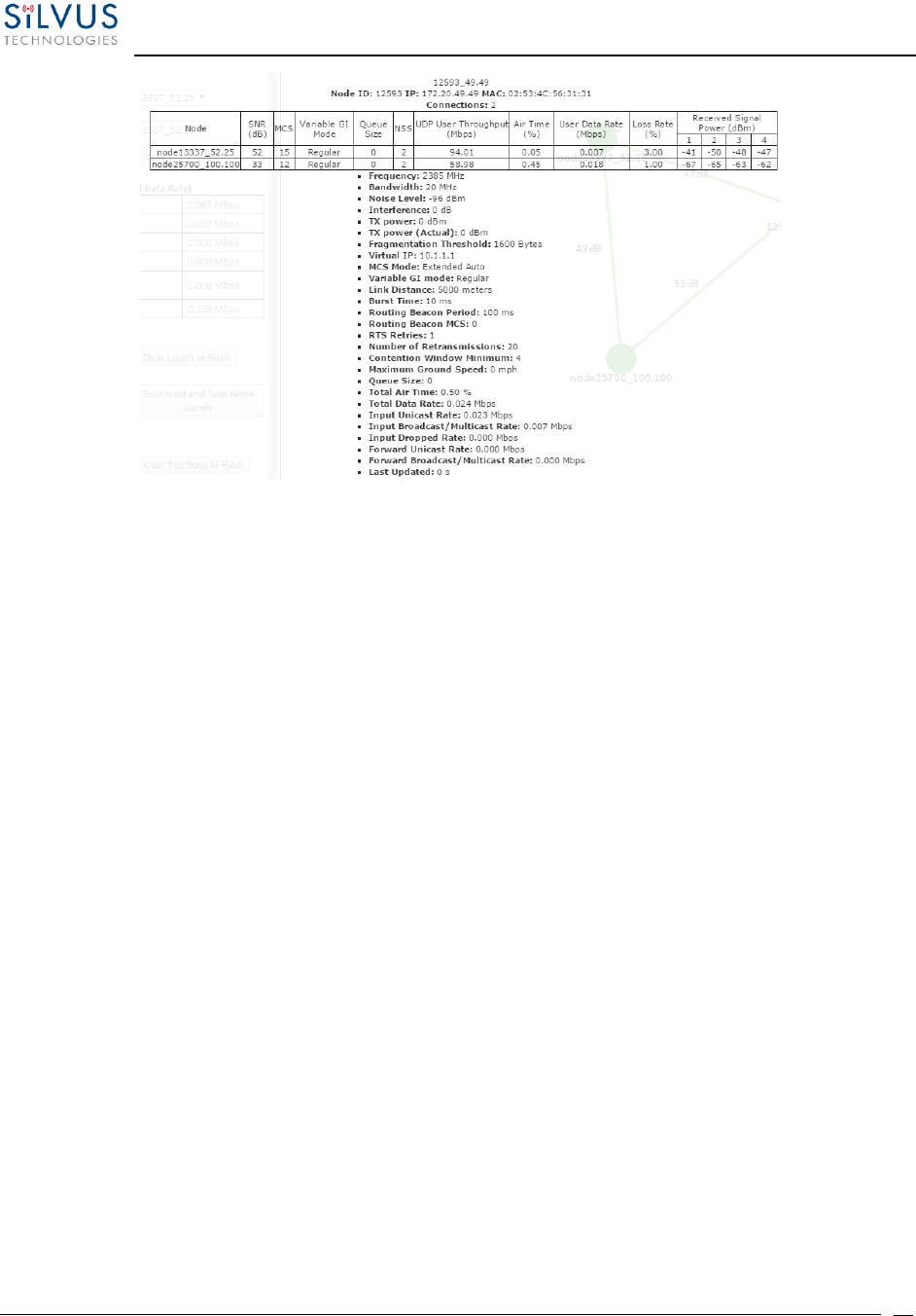
StreamCaster MIMO Radio User Manual 7/24/18
10017C000 Sensitive Company Material – Do Not Duplicate Page
95
Figure 54 Individual Node Characteristics
• Link Characteristics – By simply rolling the mouse over any link in the network, users can view key
operating characteristics of that link. Figure 55 Link Characteristics shows an example of this for
the link between ‘node25700’ and ‘node12593’. The characteristics shown are:
o SNR: The SNR of the link in each direction.
o MCS: The MCS used to transfer data in each direction.
o UDP User Throughput: The estimated UDP User Throughput available for each direction
of the link. This is estimated based on the current MCS used for transmission.
o Queue Size: Number of packets in TX Queue in each direction.
o NSS: Number of Spatial Streams in each direction.
o Air Time: Percentage of air time used in each direction
o Data Rate: Data rate in each direction
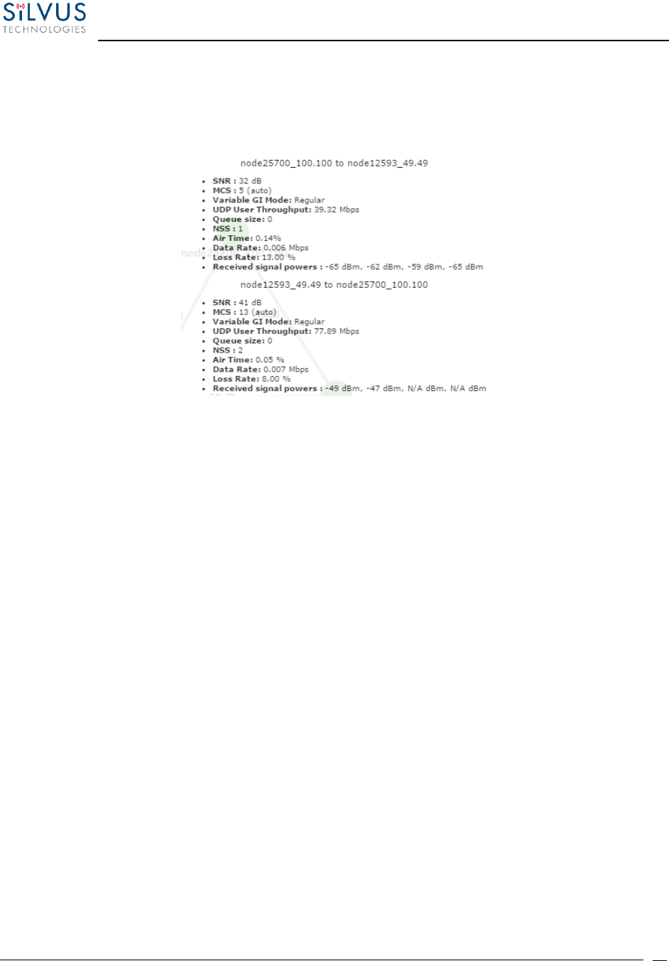
StreamCaster MIMO Radio User Manual 7/24/18
10017C000 Sensitive Company Material – Do Not Duplicate Page
96
o Data Loss Rate: Percentage of data lost during transmission
o Received Signal Powers: Received signal power for each antenna in each direction.
Figure 55 Link Characteristics
• Send Traffic Between Nodes – Users can send test traffic across radios within a network
using the built-in iPerf feature. This feature can be accessed by clicking the blue bar at the
top of the topology view, titled “Send traffic between nodes”. This will open up a drop
down menu where users can specify UDP/TCP data, source/destination, port, time to
send, and datagram size.
o Source: Radio that sends data (Client)
o Destination: Radio that is listening (Server)
o Destination port: Port number for the data transfer
o Time to Send: Amount of time user wants to send data
o Bandwidth to Send: Data rate to send, in Mbps
o Datagram Size: Size of the datagram
o Effective Bandwidth: The actual network load.
o Jitter: The variation in delays in the received packet.
o Lost/Total Datagrams: The amount of packets lost vs total packets sent

StreamCaster MIMO Radio User Manual 7/24/18
10017C000 Sensitive Company Material – Do Not Duplicate Page
97
Figure 56 iPerf Function within GUI

StreamCaster MIMO Radio User Manual 7/24/18
10017C000 Sensitive Company Material – Do Not Duplicate Page
98
5.2.2 Table View
Figure 57 Table View
The table view tab shows all the statistics and setting profiles in table view. Users can select what
is needed through the drop down menu on the upper left side. The dropdown is shown in Figure
58 Table View (Settings)
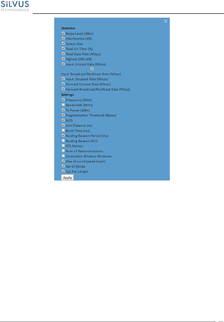
StreamCaster MIMO Radio User Manual 7/24/18
10017C000 Sensitive Company Material – Do Not Duplicate Page
99
Figure 58 Table View (Settings)

StreamCaster MIMO Radio User Manual 7/24/18
10017C000 Sensitive Company Material – Do Not Duplicate Page
100
5.2.3 Network-wide Setup
Using the network-wide setup users can configure key parameters of every node in the network
with just one click. Users simply need to check off the parameters they wish to be updated across
the network and click on Apply to apply but not write new values to flash or Save and Apply to
apply and save values to flash. The Broadcast Update Interval field determines how often, in
seconds, the new parameters will be broadcast to the entire network. A list of all nodes will
appear on the right with a check box next to each node. This box will be checked off as each node
receives the update.
Figure 59 Network-wide Setup
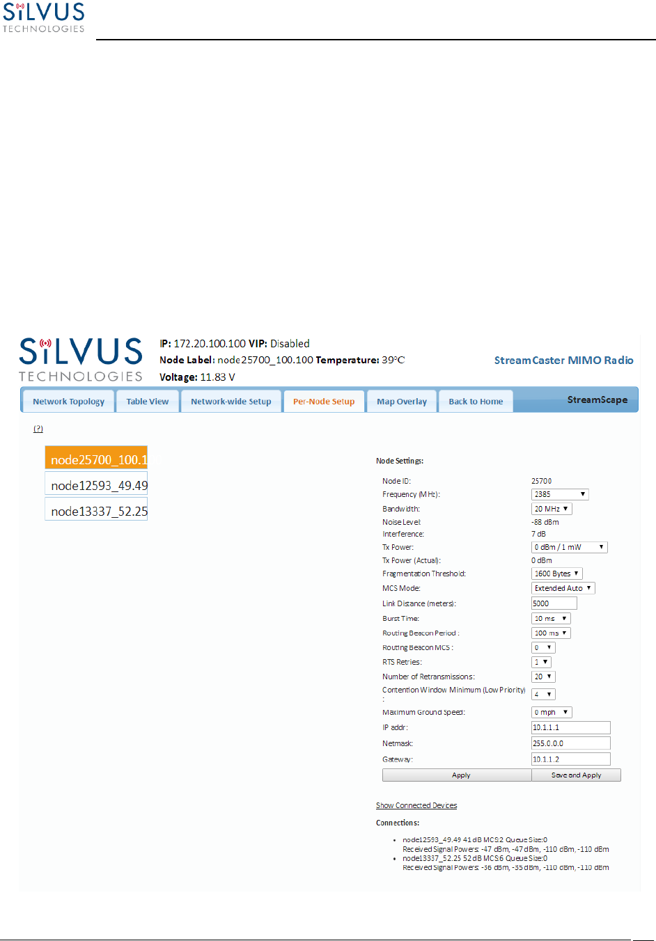
StreamCaster MIMO Radio User Manual 7/24/18
10017C000 Sensitive Company Material – Do Not Duplicate Page
101
5.2.4 Per-Node Setup
The per-node setup can be used to modify key parameters of individual nodes within the
network. As shown in Figure 60, users will see a list of all nodes available within the network. The
directly connected node is listed first with the rest ordered lexically. From here, users can click
on an individual node and modify its parameters. Any parameters changed from this interface
can either be applied or saved and applied.
In addition, this page can be used to upgrade a radio’s firmware by simply choosing the upgrade
image from your desktop and uploading it to the radio. This field can be used to upgrade the
radio root file system, linux kernel, or uboot. The upgrade system accepts the root file system
image for upgrade or a tar file containing up to 3 files (uboot, kernel, rootfs) for upgrade. A radio
reboot will be required after update before the changes take effect.
Figure 60 Per-Node Setup
StreamCaster MIMO Radio User Manual 7/24/18
10017C000 Sensitive Company Material – Do Not Duplicate Page
102
5.2.5 Map Overlay
The Map Overlay page provides an easy to use method of tracking the location of nodes in real-
time. Nodes with GPS modules attached will be placed on the map as shown in Figure 61.
Figure 61 Map Overlay
For convenience, a small copy of the network topology is displayed on the right-hand side of the
page. This allows users to clearly view the network characteristics in instances where nodes are
physically close to one another and difficult to distinguish on the map overlay.

StreamCaster MIMO Radio User Manual 7/24/18
10017C000 Sensitive Company Material – Do Not Duplicate Page
103
5.2.5.1 Map Options
There are 4 map options currently available in the Map Overlay view. The default map is
OpenStreet Maps. OpenStreet Maps and OpenStreet Maps Silvus can be saved to the radio’s
internal memory for offline use. For instructions to Download OpenStreet Maps into the radio,
see section 5.2.5.2. OpenStreet Maps Silvus is a version of OpensStreet maps which is hosted on
Silvus’ servers in case of an interruption in service with OpenStreet Maps. The Silvus maps
currently only cover the United States.
In Addition to OpenStreet Maps, Google Maps and Google Satellite are also available. This can be
changed by clicking the ‘+’ symbol at the top right of the map:
Figure 62 Google Maps
Note that Google Maps and Google Satellite require an active internet connection on the viewing
computer. These maps cannot be saved for offline use.

StreamCaster MIMO Radio User Manual 7/24/18
10017C000 Sensitive Company Material – Do Not Duplicate Page
104
Offline Map Image:
In addition to the preset map options, the user can also upload a custom image or blueprint in
place of the map.
Figure 63 Offline Map Image
To upload a custom image (800 x 600 pixels recommended), first choose the file from your
desktop. You will then need to provide the image bounds. These bounds will be the latitude of
the left and right bounds of the image and longitude of the top and bottom bounds of the image.
Once entered, click upload and there will now be a 4th option when clicking the ‘+’ at the top left
of the map overlay.

StreamCaster MIMO Radio User Manual 7/24/18
10017C000 Sensitive Company Material – Do Not Duplicate Page
105
5.2.5.2 Downloading Maps
An internet connection is required to obtain map data, however, users can cache map data on a
node beforehand. For map caching follow these steps:
1. Attach the radio to a laptop and open the advanced tab.
2. Set the Virtual IP address, netmask and gateway to values appropriate for your local
network. Your local network should be able to access the internet.
3. Attach the radio to your local network and open the Map Overlay tab.
4. Input the address of the location you wish to download
5. You now have two options for caching map data:
a. Zoom/pan around the area you are interested in at the zoom level you will be
using. This will automatically cache the map data at this zoom level.
b. Fill in the radius field (in meters), set the Min/Max zoom levels and click on
‘Seed the Map’. This is a beta feature and will attempt to cache the entire area
for all appropriate zoom levels. Users should be careful in using this feature
since it may take some time and will use up the radio’s available memory. For
reference, a radius of ~3000m will use approximately 5 percent of the total
memory.

StreamCaster MIMO Radio User Manual 7/24/18
10017C000 Sensitive Company Material – Do Not Duplicate Page
106
5.2.5.3 Manual GPS for Nodes without GPS Module
Figure 64 Placing Nodes on the Map
If there are nodes within the mesh that do not have a GPS module connected, or are located in
an area with no GPS connectivity, the user can easily place the node on the map by right clicking
on the desired location on the map and choosing which node to place there. These values will be
ignored if GPS coordinates are available via a GPS module.
StreamCaster MIMO Radio User Manual 7/24/18
10017C000 Sensitive Company Material – Do Not Duplicate Page
107
5.2.4.4 Cursor on Target (License Enabled Feature)
Figure 65 Cursor on Target Settings
Cursor on Target is an exchange standard that is used to share information about targets. CoT is
a license enabled feature.
• CoT: Enable/disable cursor on target
• CoT IP Address/Port: IP address/port for the communication to establish
• CoT Message Interval (Seconds): How often to send CoT messages
• CoT Current Date (UTC): Time stamp of the date. If Set AS Current Date/Time is selected,
it will be set as the current time displayed on your computer
• CoT Current Time (UTC): Time stamp of the time
• CoT Stale Time (Seconds): Data outside of this time window becomes invalid
• CoT Type: The event type of the target

StreamCaster MIMO Radio User Manual 7/24/18
10017C000 Sensitive Company Material – Do Not Duplicate Page
108
6. FIPS Mode
6.1 Enable FIPS Mode
The following steps are required to make the radio FIPS compliant.
1. Enable FIPS mode under Security -> Encryption tab. This will require a reboot and will
erase all setting profiles, reset the encryption key, both SSH keys, the HTTPS certificate,
and the login passwords to their factory default. It will also turn on HTTPS and Login
Authentication.
2. After the radio comes back online, you will need to login to continue. You must change
the default password of “HelloWorld,” for all three users. Do this by clicking “Change
Password,” and then follow the instructions in section 5.1.13 Admin Settings.
3. Next go to Security -> Key Management. You must change the SSH Login Key, SSH Host
Key, and HTTPS Certificate from their defaults. See section 5.1.10 under Key
Management for details.
4. Now you must create an encryption key that will be shared amongst all radios on a
network. For initial setup, you must have a direct connection to each radio from your
laptop (since a mesh cannot be formed without a shared encryption key). On the first
radio, click Generate Random Key, then click Apply. For the rest of the radios, instead
of clicking Generate Random Key, copy/paste the first generated key to the rest of the
radios under the same section.
o If you want to change the encryption key after initial setup, you must carefully
sequence the order in which you change the keys if you don’t have a direct
connection to all radios. First change the radios at the very edge of the network.
As soon as you do this, those radios will be disconnected from the network. Now
change the new radios at the edge of the network. After you have changed the
encryption key for all radios on the network, they will all reconnect again.
6.1.1 Potential User Errors
o Do not use the same encryption key you were using in non FIPS mode because these may
have been broadcasted in plain text. Generate new ones once in FIPS mode.

StreamCaster MIMO Radio User Manual 7/24/18
10017C000 Sensitive Company Material – Do Not Duplicate Page
109
6.2 List of Security Parameters
o Passwords (Basic, Advanced, and Admin User): Used to login to the radio as either Basic,
Advanced, or Admin user.
o Encryption Key (also called RF-Auth-Key): This is a 256-bit sequence, represented as 64
hex numbers. It is used to establish an encrypted connection in a network.
o SSH Host Key: This key is used for authenticating the radio to all machines that want to
connect to it via SSH.
o SSH Login Key(s): These are ecdsa private/public key pairs. They are used for authorizing
SSH access to the radios. These key pairs are used instead of passwords since they are
more secure.
o TLS Host Key (also called HTTPS Certificate): This certificate is used to establish a HTTPS
connection. The underlying elliptic curve keys can be either secp256r1, secp384r1, or
secp521r1.

StreamCaster MIMO Radio User Manual 7/24/18
10017C000 Sensitive Company Material – Do Not Duplicate Page
110
7. Wired Backbone
Wired Backbone extends the StreamCaster mesh functionality over LAN (Ethernet) and WAN (Internet)
links. This feature is transparent to end-users - they do not have to re-configure their devices in any
manner to use this feature.
The StreamCaster routing protocol will automatically detect and route data on wired links to preserve air
bandwidth.
7.1 LAN Backbone
The LAN backbone feature allows more than one radio to be connected to a LAN.
7.1.1 Implementation
One of these radios must be configured as a “gateway” radio. This radio then begins listening
promiscuously on its ethernet interface to “register” all devices on the LAN as being connected to the
gateway radio. At the same time it auto-detects other non-gateway radios connected to the LAN and
establishes “wired” links to them. StreamScape Web GUI will show LAN links with SNR of 150 dB to
differentiate from wireless links.
The non-gateway radios do not register any devices, they merely act as relays. The gateway radio will
forward traffic originating from the LAN, destined for a device attached to a wireless radio, to the non-
gateway radio that is closest to the destination. Similarly, any traffic originating from a device attached to
a remote wireless radio, destined to a device on the LAN will be forwarded by non-gateway radios to the
gateway radio. The gateway radio will then send it to the device.
Currently we support data rates of up to 65 Mbps on the LAN without encryption. Since all LAN traffic
goes via the gateway radio, this is the upper limit of all traffic that can enter or go out of the LAN from/to
devices connected to wireless radios. Of course, this limit does not affect the throughput between two
devices connected directly to the LAN backbone.
7.1.2 Use Case
Consider the following scenario. A business wants to do video monitoring of its grounds. High speed LAN
hookups are available only in the HQ building. They want to use the StreamCaster radios on towers to
provide complete coverage of the grounds. All video feeds are sent back and displayed at the HQ. To
conserve air bandwidth and possible interference to other users, we want video data to go through the
high speed LAN backbone as much as possible. The below diagram shows the scenario.
StreamCaster MIMO Radio User Manual 7/24/18
10017C000 Sensitive Company Material – Do Not Duplicate Page
111
Towers 1-3 are equipped with IP cameras attached to StreamCaster radios 1-3. Radios 4-6 are mounted
on three sides of the HQ building with their Ethernet interfaces connected to the high speed LAN. Tower
1 can only communicate wirelessly with radio 4, Tower 3 with radio 5 and Tower 2 with radio 6. Video
from Tower 1 will flow wirelessly to radio 4, then via the LAN backbone to the HQ viewer which is also
attached to the LAN backbone. Even though the radios 4-6 may communicate wirelessly, they will choose
to do so via the LAN backbone.
Figure 66 LAN Backbone Example
7.2 WAN Backbone with Roaming
The WAN backbone feature allows the wireless mesh network to extend over Internet links. Multiple
geographically separate “sites” can be connected into one single layer 2 network as long as each site has

StreamCaster MIMO Radio User Manual 7/24/18
10017C000 Sensitive Company Material – Do Not Duplicate Page
112
an uplink to the Internet. The roaming feature allows mobile devices connected to StreamCaster radios to
roam from one site to another without any network re-configuration.
7.2.1 Implementation
Each site wishing to become part of the wireless mesh needs to connect one StreamCaster radio to its
LAN. Such a radio has to be configured to connect to a remote VPN server using the N2N protocol. Radios
from multiple sites will be connected at layer 2 via the N2N VPN server creating a single broadcast domain
for such nodes. By broadcasting routing packets in this domain, the nodes will auto-detect each other and
establish WAN links. Such links will appear on the StreamScape GUI with a link SNR of 120 dB to
differentiate from LAN links (150 dB) and wireless links.
The N2N VPN server will try to establish peer-to-peer links between the radios if it can. Under some cases
(e.g. symmetric NATs), this is not possible, in which case traffic between the peers is relayed by the N2N
server.
The N2N server can be hosted at any server with a public IP on the Internet. As a proof-of-concept, a
server has been set up on Amazon Web Services. Currently we support up to 10 Mbps unencrypted
between any two sites.
7.2.2 Use Case
Consider a military scenario where a platoon of soldiers begins its mission at an HQ, then breaks up into
two groups. Each group has at least one soldier with an uplink to the Internet (provided by a 4G card). The
HQ also has an uplink to the Internet. Every soldier and the HQ have a StreamCaster radio attached to
their devices.
The soldiers in the two groups want seamless and transparent communication between 1) other soldiers
in the same group 2) soldiers in the other group 3) back to HQ. Some lone soldiers (e.g. Soldier A with a
StreamCaster radio) may break up from each group and move about on their own. As they get close to
group 1, 2 or the HQ, they should be able to immediately establish communication and talk to all other
soldiers in the network.
The StreamCaster radios connected to the uplinks in Group 1-2 and the HQ will automatically connect and
form WAN links.
Note that the WAN and LAN backbone are complementary features. E.g. at the HQ, multiple radios can
be connected to a LAN backbone so that any approaching soldier or group has a direct line of sight wireless
connection to the HQ.
StreamCaster MIMO Radio User Manual 7/24/18
10017C000 Sensitive Company Material – Do Not Duplicate Page
113
Figure 67 WAN Backbone Example
StreamCaster MIMO Radio User Manual 7/24/18
10017C000 Sensitive Company Material – Do Not Duplicate Page
114
8. Custom Frequency Plan
8.1 Accessing and Installing CFP
Figure 68 Custom Frequency Page
There are two ways to install the frequency plan. The first method is more simple. Users can simply click
on Create Custom Frequencies next to the frequency selection window to get to the custom frequency
page shown in Figure 63.
• Add: Add the frequencies in the text box to the list
• Download Plan: Download the frequency plan the radio is currently using
• Remove Plan: Removing the entire frequency plan. If this field is left empty, the radio will use the
default frequency plan.
• Download Plan: Download the current frequency plan to a file that can be uploaded to other
radios.
• Remove Frequency: Remove the currently selected frequency.
• Custom Frequencies Plan Upload: Upload the selected frequency plan.
The second method requires accessing the hidden Custom Frequency Plan page. Note radios on older
firmware only support this method.

StreamCaster MIMO Radio User Manual 7/24/18
10017C000 Sensitive Company Material – Do Not Duplicate Page
115
The hidden Custom Frequency Plan page can be accessed via http://<radio IP>/custom_freq.sh
The interface will allow an upload of a custom frequency plan file which should be in the following format:
{
"type": "custom_frequency_plan",
"name": "cfp_example",
"description": "CFP Example",
"frequencies": [
"2412",
"2417",
"2422",
"2427",
"2432",
"2437",
"2442",
"2447",
"2452",
"2457",
"2462",
"2467",
"2472",
"5745",
"5765",
"5785",
"5805",
"5825"
]
}

StreamCaster MIMO Radio User Manual 7/24/18
10017C000 Sensitive Company Material – Do Not Duplicate Page
116
(Put the above format in a Text file. Name/description can be changed)
Custom Frequency Plan Text file example:
https://drive.google.com/file/d/0ByThlCSjgHe1TDMtZ2xDXzhEblE/view?usp=sharing
The numbers can be changed to the frequencies desired. The name of the text file does not matter in
order to be utilized. After uploading the file, the web interface will be populated with
the Custom Frequency Plan.
Note:
Once installed, the Custom Frequency Plan will be cross-checked with hardware capability and the
licensed frequency range previously installed on the radio. The Custom Frequency Plan will only change
what is displayed. It will not give new frequencies that are previously out of licensed range.

StreamCaster MIMO Radio User Manual 7/24/18
10017C000 Sensitive Company Material – Do Not Duplicate Page
117
9. Streaming Response
Some users may be interested in streaming specific information from the radio e.g. RSSI, noise floor,
temperature, etc. After enabling the response they need using the above commands, the radio will
transmit the desired information in the form of UDP packets to a specific IP address and port. The format
of each report message will be in the type-length-value format as shown below:
TYPE LENGTH VALUE TYPE LENGTH VALUE …
• TYPE and LENGTH will be 16-bit unsigned integers in network-endian format.
• TYPE indicates the kind of information being transmitted. Pre-defined types are listed later in this
document.
• LENGTH indicates the length of the VALUE field in bytes, including the terminating null byte.
• VALUE will be ASCII-encoded text terminated with a null byte ('\0').
• A single report will comprise of a set of type-length-value fields beginning with a “begin” report
type. It will have a type which is specific to the type of report being generated, length of 1 byte
and a value of an empty string (“”). Note the empty string is still null terminated.
• Each report will end with an end of report which has type 1 (type = end of report, length = 1, value
= "").
• The empty string listed above has a NULL character and has length 1. Any length number in the
streaming report includes the NULL character
• A UDP packet may contain more than one report.
• The UDP packets have a maximum size of 1400 bytes.

StreamCaster MIMO Radio User Manual 7/24/18
10017C000 Sensitive Company Material – Do Not Duplicate Page
118
9.1 RSSI and Noise Floor Reporting
The type/length/value for RSSI and noise floor reporting are listed in the following table:
Report Type
Data Type
Information
5009
Empty string ""
Begin of RSSI report
5010
Float
Revision number for RSSI report
5000
Integer
Raw signal power of first antenna, represented
in half dBm steps.
5001
Integer
Raw signal power of second antenna
represented in half dBm steps.
5002
Integer
Raw signal power of third antenna represented
in half dBm steps.
5003
Integer
Raw signal power of fourth antenna
represented in half dBm steps.
5004
Integer
Raw noise power represented in half dBm
steps.
5005
32-bit integer
Sync signal power (from digital domain, see
note below).
5006
32-bit integer
Sync noise power (from digital domain, see
note below).
5007
16-bit integer
Node ID of the radio.
5008
32-bit integer
Report sequence number, increments for every
report, resets after 9999.
1
Empty string ""
End of report.
Table 22 RSSI Reporting Format
Note:
The sync noise and power (types 5005, 5006) are special values obtained after packet processing in the
digital domain. They cannot be directly compared to the raw signal and noise values. To obtain an SNR
from these values the user needs to run the below formula on these values:
X = sync signal power;
Y = sync noise power;

StreamCaster MIMO Radio User Manual 7/24/18
10017C000 Sensitive Company Material – Do Not Duplicate Page
119
Z = (Y-X)/51
SNR_mw = (X – 12 * Z)/(64 * Z)
SNR_db = 10 * log(SNR_mw)/log(10)
SNR_db is the SNR in dB and it is averaged across all antennae.
The SNR obtained above is more accurate when the real SNR goes below 10 dB. Above 10 dB, the SNR
obtained from the raw signal and noise values are more accurate.
Below is an example of the RSSI report:
Report Type
Length
Information
5009
1
""
5010
4
"1.0"
5008
5
"2333"
5000
5
"-43"
5001
5
"-31"
5002
5
"-28"
5003
5
"-66"
5004
5
"-190"
5005
8
"8604568"
5006
8
"8861322"
5007
5
"1025"
1
1
""
Table 23 Sample RSSI Report
The corresponding raw UDP dump in hexadecimal format is attached below. For the purpose of easier
reading, each byte is separated by a space, and each item is separated by a new line. The real streaming
report is continuous without any spaces or newlines and is currently 109 bytes long.
13 ffffff91 0 1 0
13 ffffff92 0 4 31 2e 30 0
13 ffffff90 0 5 32 33 33 33 0
13 ffffff88 0 5 20 2d 34 33 0
13 ffffff89 0 5 20 2d 33 31 0
13 ffffff8a 0 5 20 2d 32 38 0
13 ffffff8b 0 5 20 2d 36 36 0
13 ffffff8c 0 5 2d 31 39 30 0
13 ffffff8d 0 a 20 20 38 36 30 34 35 36 38 0

StreamCaster MIMO Radio User Manual 7/24/18
10017C000 Sensitive Company Material – Do Not Duplicate Page
120
13 ffffff8e 0 a 20 20 38 38 36 31 33 32 32 0
13 ffffff8f 0 5 31 30 32 35 0
0 1 0 1 0

StreamCaster MIMO Radio User Manual 7/24/18
10017C000 Sensitive Company Material – Do Not Duplicate Page
121
9.2 Temperature Reporting
The type, length and value for temperature reporting are listed in the following table:
Report Type
Data Type
Data
8
Empty string ""
Begin of temperature report.
9
Float
Revision number for temperature report.
2
Integer
Current Temperature on the radio.
3
Integer
Maximum Temperature reached on the radio
after last booting.
4
Integer
Overheat Count: number of times the radio
temperature has exceeded
temp_reporting_max_threshold.
1
Empty string ""
End of report
Table 24 Temperature Reporting Format

StreamCaster MIMO Radio User Manual 7/24/18
10017C000 Sensitive Company Material – Do Not Duplicate Page
122
9.3 Voltage Reporting
The type, length and value for temperature reporting are listed in the following table:
Report Type
Data Type
Data
4001
START REPORT
Indicates start of voltage monitoring
report
1
END REPORT
Indicates end of report
4003
REVISION_REPORT
Indicates revision of this report,
currently always “1.1”
4004
CUR_VOLTAGE_REPORT
Current voltage value as a floating
point string
4005
MIN_VOLTAGE_REPORT
Minimum voltage seen so far, as a
floating point string
4006
MAX_VOLTAGE_REPORT
Maximum voltage seen so far, as a
floating point string
4007
UNDERVOLTAGE_COUNT
_REPORT
Number of times voltage dropped
below min threshold, as an integer
string
4008
OVERVOLTAGE_COUNT_
REPORT
Number of times vltage spiked above
max threshold, as an integer string.
Table 25 Voltage Reporting Format

StreamCaster MIMO Radio User Manual 7/24/18
10017C000 Sensitive Company Material – Do Not Duplicate Page
123
10. Setting up an Iperf Test
10.1 Required Equipment
• Two laptops with jperf installed. It is beyond the scope of this manual to cover the
installation and operation of these tools. The laptops must be on the same subnet but not
necessarily the same subnet as the radios (172.20.xx.yy). It is not required for the user to
set a secondary IP address on the radio to perform this test. It is recommended the iperf
or jperf tests are first conducted between the laptops using an Ethernet switch or cross-
over Ethernet cable between them to verify the laptops and iperf/jperf tools.
• Two or more StreamCaster radios properly configured.
10.2 Running Iperf Test
• Connect a laptop to one StreamCaster radio using the Ethernet cable.
• Connect the other laptop to another StreamCaster radio.
• Power up the radios and verify the radios are booted and connected wirelessly.
• At the receiver side type the following in a terminal
o iperf –s –u -i 1
• At the transmitter side type the following in a terminal
o iperf –c receiver_laptop_ip_address –u –i 1 –b 1M –t 60

StreamCaster MIMO Radio User Manual 7/24/18
10017C000 Sensitive Company Material – Do Not Duplicate Page
124
11. Precautions and Recommendations
11.1 Saving the Radio Configuration
It is very important that the radio does not lose power during any configuration changes in which
the user requests a “save and apply” operation. Partial saving of the configuration to the radio
due to power interruption may disable the radio requiring reprogramming at the factory. Also,
please wait for a “done” feedback at the web interface before proceeding to any other
configuration changes.

StreamCaster MIMO Radio User Manual 7/24/18
10017C000 Sensitive Company Material – Do Not Duplicate Page
125
12. Troubleshooting
12.1 LED Issues
• If flashing red LED is present, radio is in safe boot mode. Click save and apply to resume
normal operation.
• If LED is orange and node won’t connect to another node, click “restore factory defaults”
on both radios to ensure all settings are reverted to factory settings.
12.2 Intermittent Link
• In a long range scenario if SNR is good but link drops unexpectedly check link distance
parameter and make sure that the link distance is set the same on all radios and
sufficiently large enough.
• Check interference levels as strong interference can result in an intermittent link.

StreamCaster MIMO Radio User Manual 7/24/18
10017C000 Sensitive Company Material – Do Not Duplicate Page
126
13. FCC Notice
13.1 FCC Identifier: N2S-SC3500
Silvus Model #: SC3500-243541
Equipment Class: Digital Transmission System
The following parameters must be used to be compliant to the appropriate FCC requirements:
Antenna: 3dB Omni (AOV3T245515575)
Bandwidth: 20MHz
Maximum Output Power across Frequency Range #1: 495.28mW from 2427MHz to 2447MHz
Maximum Output Power across Frequency Range #2: 493.62mW from 5745MHz to 5830MHz
13.2 FCC Identifier: N2S-SC3822
Silvus model #: SC3822-245580
Equipment Class: Digital Transmission System
The following parameters must be used to be compliant to the appropriate FCC requirements:
Antenna: 3dB Omni (AOV3T245515575)
Bandwidth: 20MHz
Maximum Output Power across Frequency Range #1: 268.64mW from 2420MHz to 2450MHz
Maximum Output Power across Frequency Range #2: 329.02mW from 5760MHz to 5810MHz
13.3 FCC Identifier: N2S-SC42-245
Silvus model #: SC4210-245-BB, SC4240-245-BB
Equipment Class: Digital Transmission System

StreamCaster MIMO Radio User Manual 7/24/18
10017C000 Sensitive Company Material – Do Not Duplicate Page
127
The following parameters must be used to be compliant to the appropriate FCC requirements:
Antenna: 2.1dBi Omni Antennas (AOV2S230515)
Bandwidth: 10MHz
Maximum Output Power @ Frequency #1: 810.17mW @ 2430MHz
Maximum Output Power @ Frequency #2: 795.3mW @ 2440MHz
13.4 FCC Identifier: N2S-SC44-245
Silvus model #: SC4410-235-SBST, SC4480-235-SBST
Equipment Class: Digital Transmission System
The following parameters must be used to be compliant to the appropriate FCC requirements:
Antenna: 2.1dBi Omni Antennas (AOV2S230515)
Bandwidth: 10MHz
Maximum Output Power @ Frequency #1: 582.1mW @ 2430MHz
Maximum Output Power @ Frequency #2: 523.6mW @ 2440MHz
13.5 FCC Identifier: N2S-SC42-520
Silvus model #: SC4210E-520-BB, SC4240E-520-BB
Equipment Class: Digital Transmission System
The following parameters must be used to be compliant to the appropriate FCC requirements:
Antenna: 6dBi Omni Antennas (Peak Antennas CO520-6-LS)
Bandwidth: 20MHz
Maximum Output Power @ Frequency #1: 414.03 mW @ 5220MHz
Maximum Output Power @ Frequency #2: 498.92 mW @ 5240MHz

StreamCaster MIMO Radio User Manual 7/24/18
10017C000 Sensitive Company Material – Do Not Duplicate Page
128
13.6 FCC Identifier: N2S-SC44-520
Silvus model #: SC4410E-520-SBST, SC4480E-520-SBST
Equipment Class: Digital Transmission System
The following parameters must be used to be compliant to the appropriate FCC requirements:
Antenna: 6dBi Omni Antennas (Peak Antennas CO520-6-LS)
Bandwidth: 20MHz
Maximum Output Power @ Frequency #1: 248.66 mW @ 5220MHz
Maximum Output Power @ Frequency #2: 246.52 mW @ 5240MHz
13.7 Notes
This equipment has been tested and found to comply with the limits for a class B digital device pursuant to Part 15 of the FCC Rules.
These limits are designed to provide reasonable protection against harmful interference in a residential installation. This equipment
generates, uses and can radiate radio frequency energy and if not installed and used in accordance with the instructions, may cause
harmful interference to radio communications. However, there is no guarantee that interference will not occur in a particular
installation. If this equipment does cause harmful interference to radio or television reception, which can be determined by turning
the equipment off and on, the user is encouraged to try to correct the interference by one or more of the following measures:
* Reorient or relocate the receiving antenna.
* Increase the separation between the equipment and receiver.
* Connect the equipment into an outlet on a circuit different from that to which the receiver is
connected.
* Consult the dealer or an experienced radio/TV technician for help.
In order to maintain compliance with FCC regulations, shielded cables must be used with this
equipment. Operation with non-approved equipment or unshielded cables is likely to result in
interference to radio and TV reception. The user is cautioned that changes and modifications
made to the equipment without the approval of the manufacturer could void the user’s authority
to operate the equipment.
To satisfy RF exposure requirements, this device and its antennas must operate with a separation
distance of at least 20 cm from all persons and must not be co-located or operating in conjunction
with any other antenna or transmitter.

StreamCaster MIMO Radio User Manual 7/24/18
10017C000 Sensitive Company Material – Do Not Duplicate Page
129
14. Notes Regarding CE Mark (SC4200-206-EB and
SC4400-206-SBST models only)
The following Silvus Technologies models are declared to conform to CE Mark requirements:
Silvus P/N: SC4240-206-EB, SC4480-206-SBST
Relevant standards:
ETSI EN 302 064 V2.1.1 (2016-09), Wireless Video Links, Harmonized Standard
ETSI EN 301 489-1 V2.2.0 (2017-03), EMC, Common Technical Requirements
ETSI EN 301 489-28 V1.1.1 (2004-09), EMC, Specific conditions for wireless digital video links
EN 60950-1, Information Technology Equipment, Safety
Frequency range: 2025-2110 MHz
Maximum RF power: 500 mW per channel, up to a maximum EIRP of 1.6 watts for the SC4240-206-
EB, and 3.2 watts for the SC4480-206-SBST
Antenna: 2.15dBi Omni Antennas (AOV2D230515)
Cable: Silvus cable assembly (SC22-PRICBL02-6)
External Bandpass Filter:
Microwave Filter Co. model 3813
(a filter of equivalent performance may also be used, contact Silvus Technologies customer
support for more information)
AC Adapter (if used): EDAC Power Electronics EA10523C-120 (this adapter is approved for indoor use
only) (this adapter was certified by the manufacturer to IEC 60950-1)
External DC supply: If the customer provides DC power from their own source, the supply should be
fused for a 5-amp circuit.
Safe Working Distance:
Maintain safe working distance of minimum 20cm. For more details, refer to TUV report no.
SD72128709-0617A-0617C, “Radio Frequency Exposure Verification of the Silvus Technologies
Inc. StreamCaster SC420-206 and SC4480 Tactical MIMO Radio EN 62311 January 2008” (copy of
report available upon request). The CE Mark Technical File is available upon request for
inspection.
To satisfy RF exposure requirements, this device and its antennas must operate with a
separation distance of at least 20 cm from all persons and must not be co-located or operating
in conjunction with any other antenna or transmitter, except in accordance with RED RF
Exposure requirements.

StreamCaster MIMO Radio User Manual 7/24/18
10017C000 Sensitive Company Material – Do Not Duplicate Page
130
This equipment has been constructed so that the product complies with the requirement of with Article
10(2) as it can be operated in at least one Member State as examined and the product is compliant with
Article 10(10) as it has no restrictions on putting into service in all EU member states.
See restrictions mentioned in ERC Recommendation 25-10, Table 7-C2, for guidance of restrictions
applicable to specific countries.
Table 26 Additional Restrictions on Band C2
StreamCaster MIMO Radio User Manual 7/24/18
10017C000 Sensitive Company Material – Do Not Duplicate Page
131