Simcom 0805152008527 850/900/1800/1900 GSM/GPRS+GPS module User Manual
Shanghai Simcom Ltd. 850/900/1800/1900 GSM/GPRS+GPS module
Simcom >
User Manual

Development Kit Manual
SIM548C-EVB_UGD_V1.01

SIM548C EVB User Guide
SIM548C-EVB_ UGD _V1.01 04.05.2008
2
Document Title: SIM548C EVB User Guide
Version: 1.01
Date: 2008-05-04
Status: Release
Document Control ID: SIM548C-EVB_UGD_V1.01
General Notes
SIMCom offers this information as a service to its customers, to support application and
engineering efforts that use the products designed by SIMCom. The information provided is
based upon requirements specifically provided to SIMCom by the customers. SIMCom has
not undertaken any independent search for additional relevant information, including any
information that may be in the customer’s possession. Furthermore, system validation of this
product designed by SIMCom within a larger electronic system remains the responsibility of
the customer or the customer’s system integrator. All specifications supplied herein are
subject to change.
Copyright
This document contains proprietary technical information which is the property of SIMCom
Limited., copying of this document and giving it to others and the using or communication of
the contents thereof, are forbidden without express authority. Offenders are liable to the
payment of damages. All rights reserved in the event of grant of a patent or the registration of
a utility model or design. All specification supplied herein are subject to change without
notice at any time.
Copyright © Shanghai SIMCom Wireless Solutions Ltd.2008

SIM548C EVB User Guide
SIM548C-EVB_ UGD _V1.01 04.05.2008
3
Contents
Contents ............................................................................................................................................3
1 Overview........................................................................................................................................6
2 EVB accessory ...............................................................................................................................8
3 Accessory interface ........................................................................................................................9
3.1 Power interface.....................................................................................................................9
3.2 Audio interface .....................................................................................................................9
3.3 SIM card interface..............................................................................................................10
3.4 Antenna interface ...............................................................................................................11
3.4.1 GSM antenna interface.............................................................................................11
3.4.2 GPS antenna interface ..............................................................................................12
3.5 RS232 interface..................................................................................................................13
3.5.1 GSM part ..................................................................................................................13
3.5.2 GPS part ...................................................................................................................14
3.6 Operating status LED.........................................................................................................15
3.6.1 GSM part ..................................................................................................................15
3.6.2 GPS part ...................................................................................................................16
4 Test interface ................................................................................................................................17
4.1 GSM serial ports ................................................................................................................17
4.2 LCD & ADC ......................................................................................................................18
4.3 GPS control & I/O..............................................................................................................19
4.5 GPS serial ports and power ................................................................................................20
5 EVB and accessory equipment.....................................................................................................21
6 Illustration ....................................................................................................................................22
6.1 GSM part............................................................................................................................22
6.1.1 Running ....................................................................................................................22
6.1.2 Connecting Net and calling ......................................................................................22
6.1.3 Downloading ............................................................................................................22
6.1.4 Turn off.....................................................................................................................22
6.1.5 Charging ...................................................................................................................23
6.2 GPS part .............................................................................................................................23
6.1.1 Running: ...................................................................................................................23
6.1.2 Tracking the satellite signals ....................................................................................24
6.1.3 Downloading ............................................................................................................24
6.1.4 Turn off and Reset ....................................................................................................24

SIM548C EVB User Guide
SIM548C-EVB_ UGD _V1.01 04.05.2008
4
Figure Index
FIGURE 1: TOP VIEW............................................................................................................................6
FIGURE 2: BOTTOM VIEW ..................................................................................................................6
FIGURE 3: EVB ACCESSORY...............................................................................................................8
FIGURE 4: POWER INTERFACE..........................................................................................................9
FIGURE 5: AUDIO INTERFACE ...........................................................................................................9
FIGURE 6: SIM CARD INTERFACE...................................................................................................10
FIGURE 7: GSM ANTENNA INTERFACE.......................................................................................... 11
FIGURE 8: GPS ANTENNA INTERFACE...........................................................................................12
FIGURE 9: GSM PART SERIAL PORTS..............................................................................................13
FIGURE 10: GPS PART SERIAL PORTS.............................................................................................14
FIGURE 11: GSM PART LED...............................................................................................................15
FIGURE 12: GPS PART LED................................................................................................................16
FIGURE 13: TEST INTERFACE OVERVIEW.....................................................................................17
FIGURE 14: GSM SERIAL PORTS......................................................................................................17
FIGURE 15: LCD & ADC INTERFACE...............................................................................................18
FIGURE 16: GPS CONTROL & I/O INTERFACE...............................................................................19
FIGURE 17: GPS SERIAL PORTS .......................................................................................................20
FIGURE 18: EVB AND ACCESSORY EQUIPMENT .........................................................................21

SIM548C EVB User Guide
SIM548C-EVB_ UGD _V1.01 04.05.2008
5
SCOPE
This document give the usage of SIM548C EVB, user can get useful info about the SIM548C
EVB quickly through this document. Using SIM548C EVB, user can demo SIM548C module.
Operating of module may interfere with medical devices like hearing aides and pacemakers.
Please always keep the module more than 20 centimeters away from such medical devices when
the module is powered on.
The module has been tested and found to comply with the limits for a Class B digital device,
pursuant to part 15 of the FCC Rules. These limits are designed to provide reasonable protection
against harmful interference in a residential installation.
The module generates, uses and can radiate radio frequency energy and ,if not installed and used
In accordance with the instructions, may cause harmful interference to radio communications.
However, there is no guarantee that interference will not occur in a particular installation. If the
module does cause harmful interference to radio or television reception, which can be determined
by turning the equipment off and on , the user is encouraged to try to correct the interference by
one or more of the following measures:
------Reorient or relocate the receiving antenna.
------Increase the separation between the equipment and receiver.
------Connect the equipment into an outlet on a circuit different from that to which the
receiver is connected.
-------Consult the dealer or an experienced radio technician for help
This device complies with part 15 of the FCC Rules. Operation is subject to the following two
conditions:
(1) This device may not cause harmful interference;
(2) This device must accept any interference received, including interference that may cause
undesired operation.
This document is subject to change without notice at any time.
SIM548C EVB User Guide
SIM548C-EVB_ UGD _V1.01 04.05.2008
6
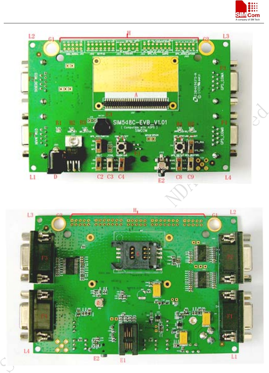
1 Overview
Figure 1: TOP view
Figure 2: BOTTOM view
A: 60-pin connector, SIM548C module interface
B1-B5: LED indicator
B1: VBAT ON/OFF
B2: GSM net status
B3: The GSM part of the module ON/OFF status
B4: 1PPS output for GPS part

SIM548C EVB User Guide
SIM548C-EVB_ UGD _V1.01 04.05.2008
7
B5: GPS TX/RX status
C1-C9: Key control for various functions
C1: GSM part power-up / power down control (button Z101)
C2: VBAT ON/OFF control (shifter S102)
C3: VCHG ON/OFF control (shifter S105)
C4: GSM part program download control (shifter S101)
C5: GPS part power ON/OFF control (shifter S107)
C6: GPS part reset control (button Z102)
C7: GPS part RX/TX LED status selective shifter (shifter S106)
C8: GPS part wake up control (shifter S103)
C9: GPS part program download control (shifter S104)
D: Power source adapter interface
E1-E3: Audio interface
E1: Handset interface
E2: Headphone interface
E3: Buzzer
F1-F4: Serial ports
F1: Main serial port for downloading, AT command transmitting, data exchanging
F2: Debug serial port
F3: GPS part serial port A
F4: GPS part serial port B
G1-G2: Hole for antenna fixed
G1: Hole for GSM antenna fixed
G2: Hole for GPS antenna fixed
H: Expand port, such as serial ports, display port
I1-I4: Hole for EVB board fixed
K: SIM card connector
L: 3.3V Back-up battery for GPS part
SIM548C EVB User Guide
SIM548C-EVB_ UGD _V1.01 04.05.2008
8
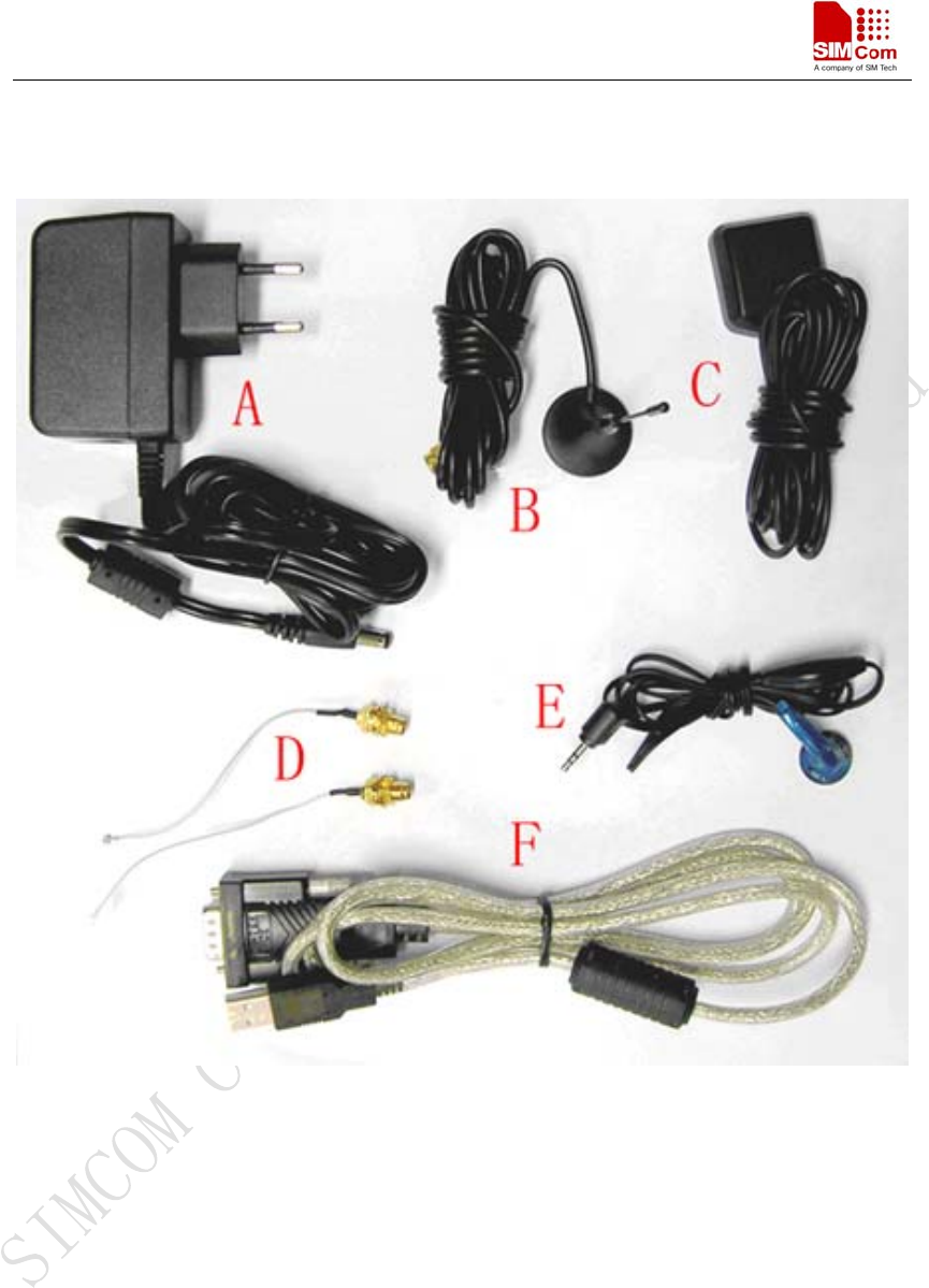
2 EVB accessory
Figure 3: EVB accessory
A: antenna
A: 5V DC source adapter
B: GSM antenna
C: GPS antenna
D: RF cable
E: Earphone
F: USB to serial port line
SIM548C EVB User Guide
SIM548C-EVB_ UGD _V1.01 04.05.2008
9
3 Accessory interface
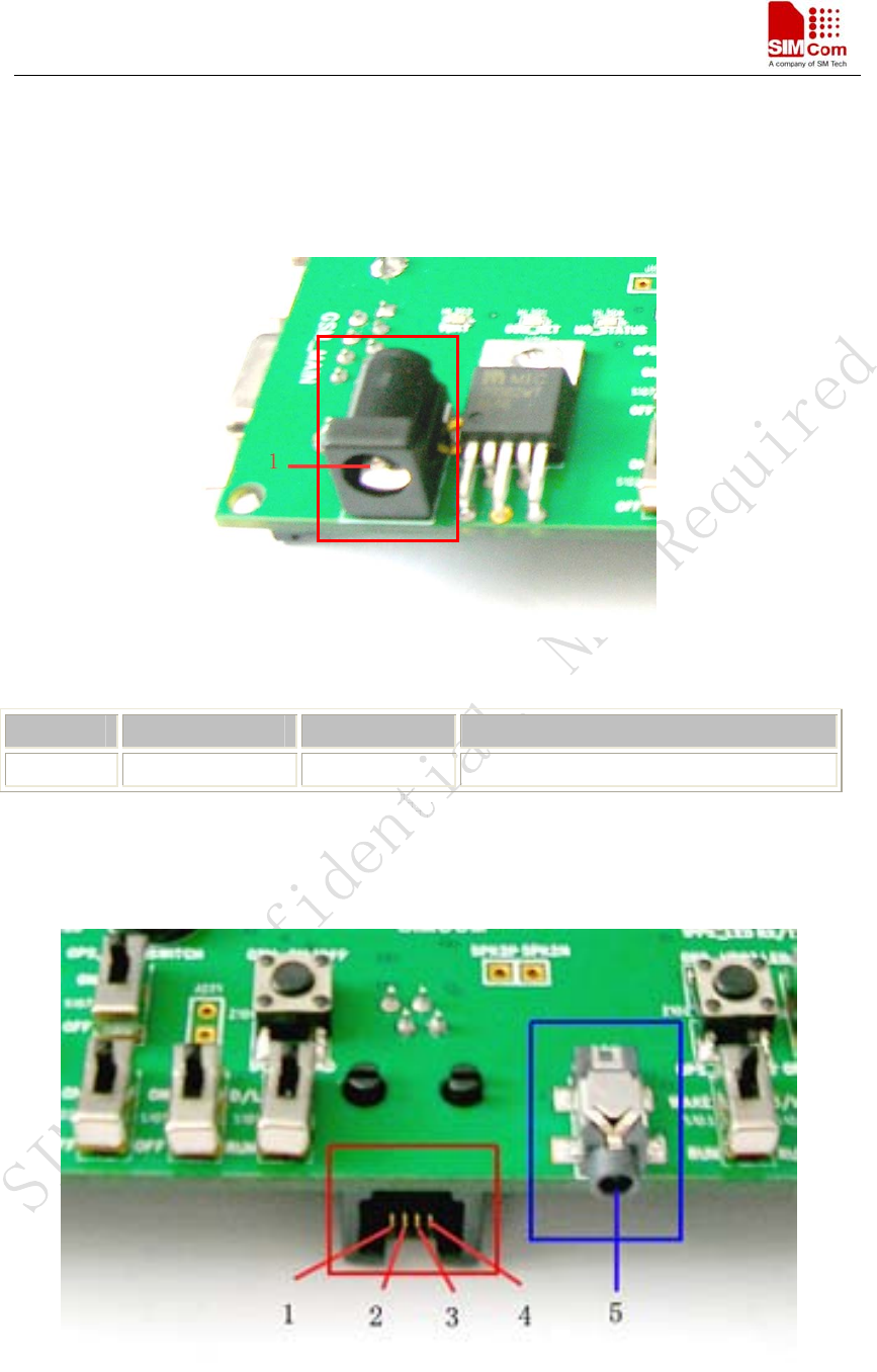
3.1 Power interface
Figure 4: Power interface
Pin Signal I/O Description
1 Adapter input I 5V/2.5A DC source input
3.2 Audio interface
Figure 5: Audio interface
SIM548C EVB User Guide
SIM548C-EVB_ UGD _V1.01 04.05.2008
10
Headset interface:
Pin Signal I/O Description
1 MIC1P I Positive microphone input
2 SPK1P O Positive microphone input
3 SPK1N O Negative microphone input
4 MIC1N I Negative microphone input
Headphone interface:
Pin Signal Input/Output Description
5 MIC2P&SPK2P I/O Auxiliary positive input and output
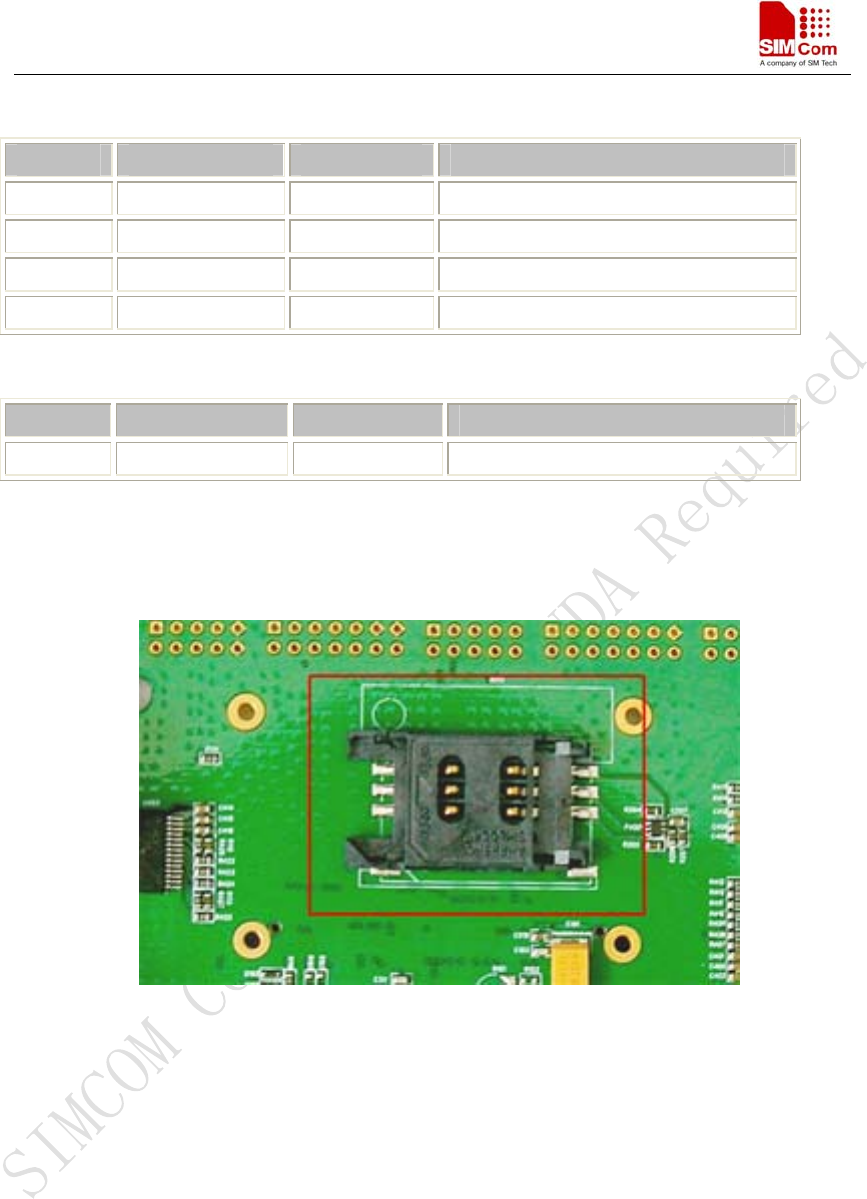
3.3 SIM card interface
Figure 6: SIM card interface
Note: Please refer to SIM548C User Guide, detailed in Chapter 3.11 SIM interface.
SIM548C EVB User Guide
SIM548C-EVB_ UGD _V1.01 04.05.2008
11
3.4 Antenna interface
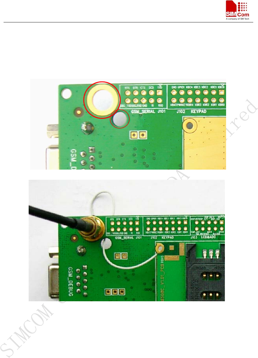
3.4.1 GSM antenna interface
Figure 7: GSM antenna interface
SIM548C EVB User Guide
SIM548C-EVB_ UGD _V1.01 04.05.2008
12
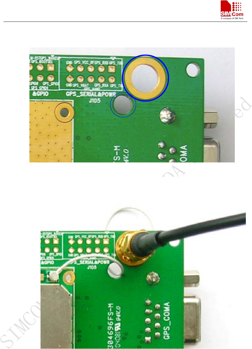
3.4.2 GPS antenna interface
Figure 8: GPS antenna interface
SIM548C EVB User Guide
SIM548C-EVB_ UGD _V1.01 04.05.2008
13
3.5 RS232 interface
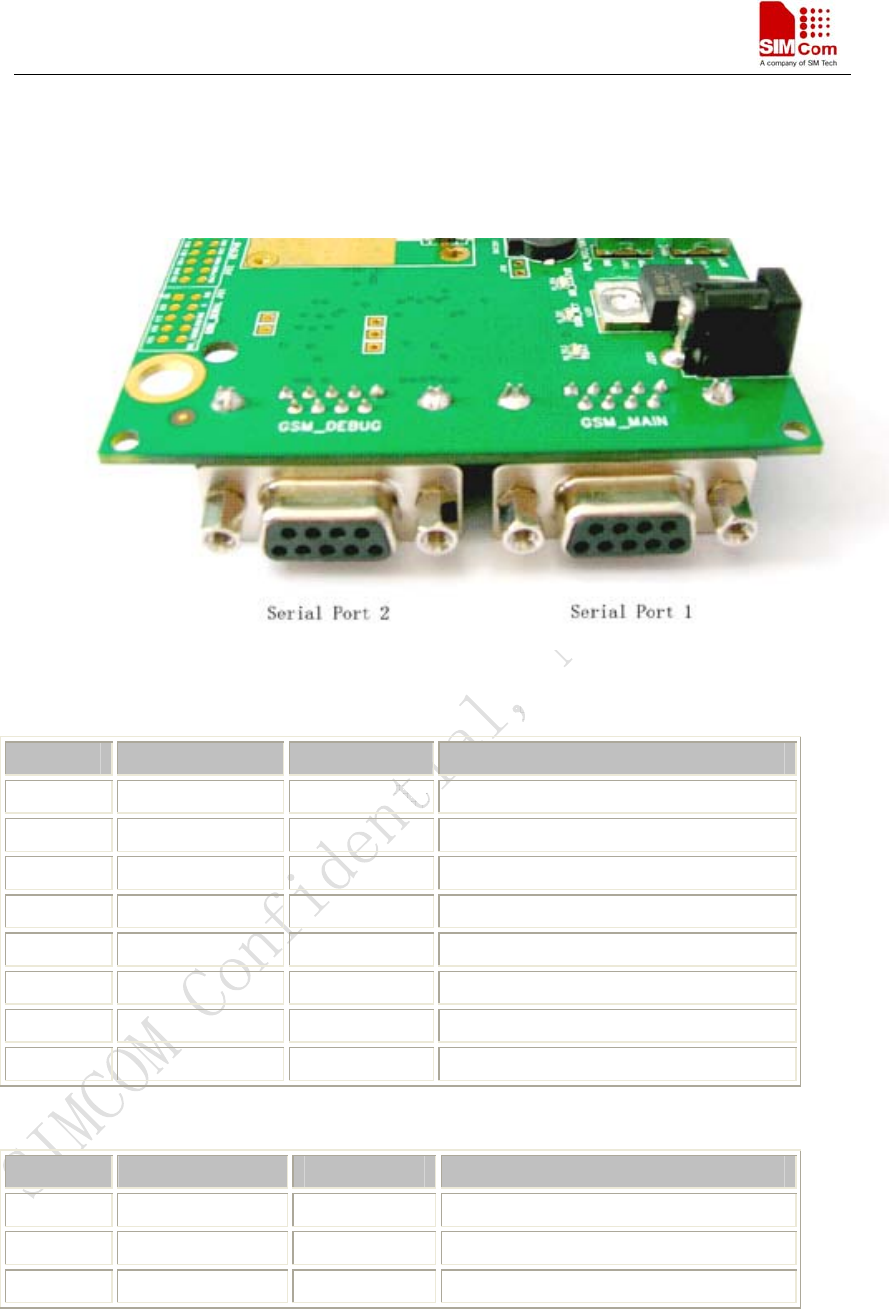
3.5.1 GSM part
Figure 9: GSM part serial ports
Serial Port 1
Pin Signal I/O Description
1 DCD O Data carrier detection
2 TXD O Transmit data
3 RXD I Receive data
4 DTR I Data Terminal Ready
5 GND GND
7 RTS I Request to Send
8 CTS O Clear to Send
9 RI O Ring Indicator
Serial Port 2
Pin Signal I/O Description
2 DEBUG_TX O Transmit data
3 DEBUG_RX I Receive data
5 GND GND
SIM548C EVB User Guide
SIM548C-EVB_ UGD _V1.01 04.05.2008
14
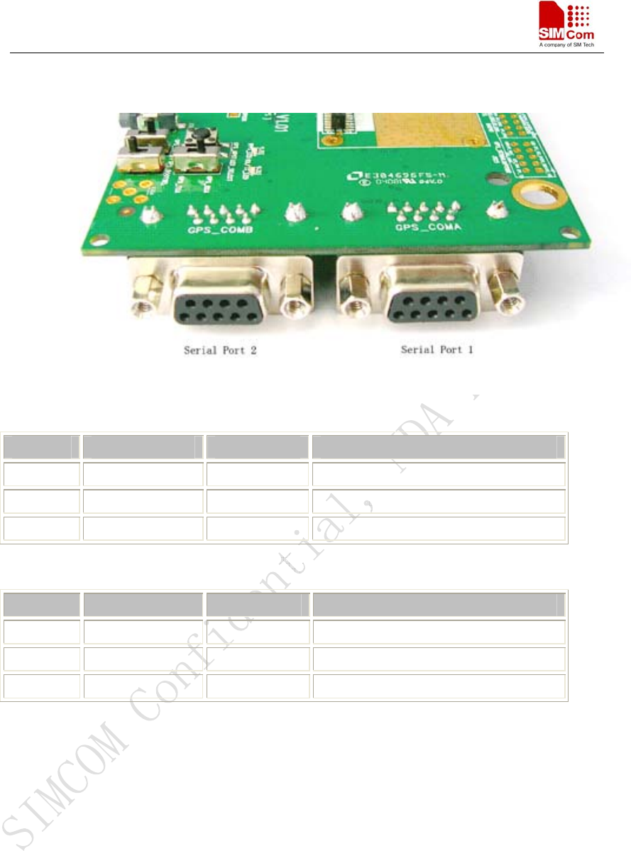
3.5.2 GPS part
Figure 10: GPS part serial ports
Serial port 1:
Pin Signal I/O Description
2 GPS_TXA O Transmit data
3 GPS_RXA I Receive data
5 GND GND
Serial port 2:
Pin Signal I/O Description
2 GPS_TXB O Transmit data
3 GPS_RXB I Receive data
5 GND GND
SIM548C EVB User Guide
SIM548C-EVB_ UGD _V1.01 04.05.2008
15
3.6 Operating status LED
3.6.1 GSM part
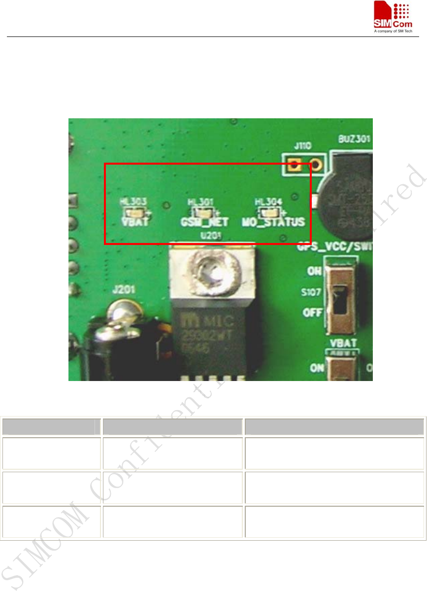
Figure 11: GSM part LED
Name Description STATUS
VBAT_LED VBAT ON/OFF indicator Bright: VBAT ON;
Extinct: VBAT OFF
GSM_NET_LED GSM_NET status indicator Blinking at a certain frequency
according to various GSM net status
MO_STATUS_LED GSM part status indicator Not used, will be configured in our
latter software.
SIM548C EVB User Guide
SIM548C-EVB_ UGD _V1.01 04.05.2008
16
3.6.2 GPS part
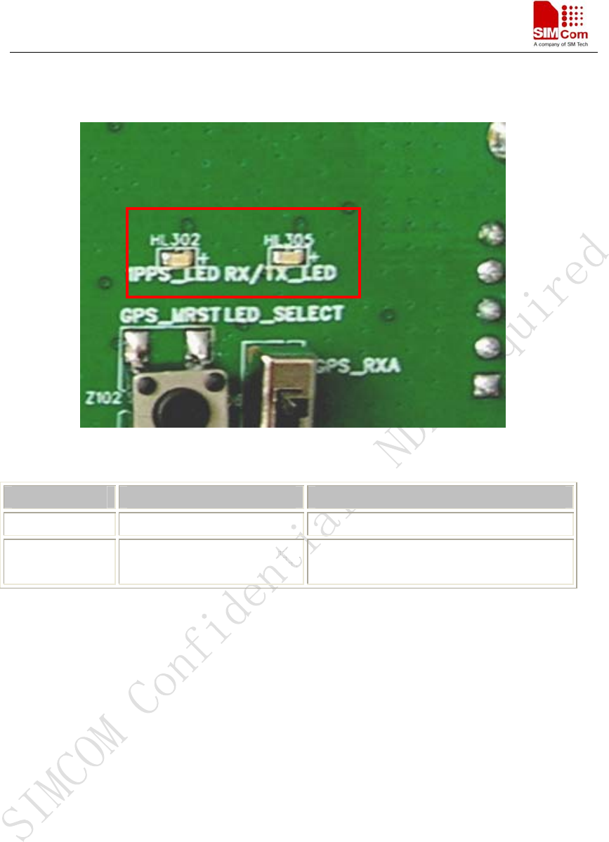
Figure 12: GPS part LED
Name Description STATUS
1PPS_LED 1PPS signal indicator Not used currently
RX/TX_LED Run or download indicator Run normally: Blinking at 1Hz
Download: Blinking rapidly
SIM548C EVB User Guide
SIM548C-EVB_ UGD _V1.01 04.05.2008
17
4 Test interface
Figure 13: Test interface overview
4.1 GSM serial ports
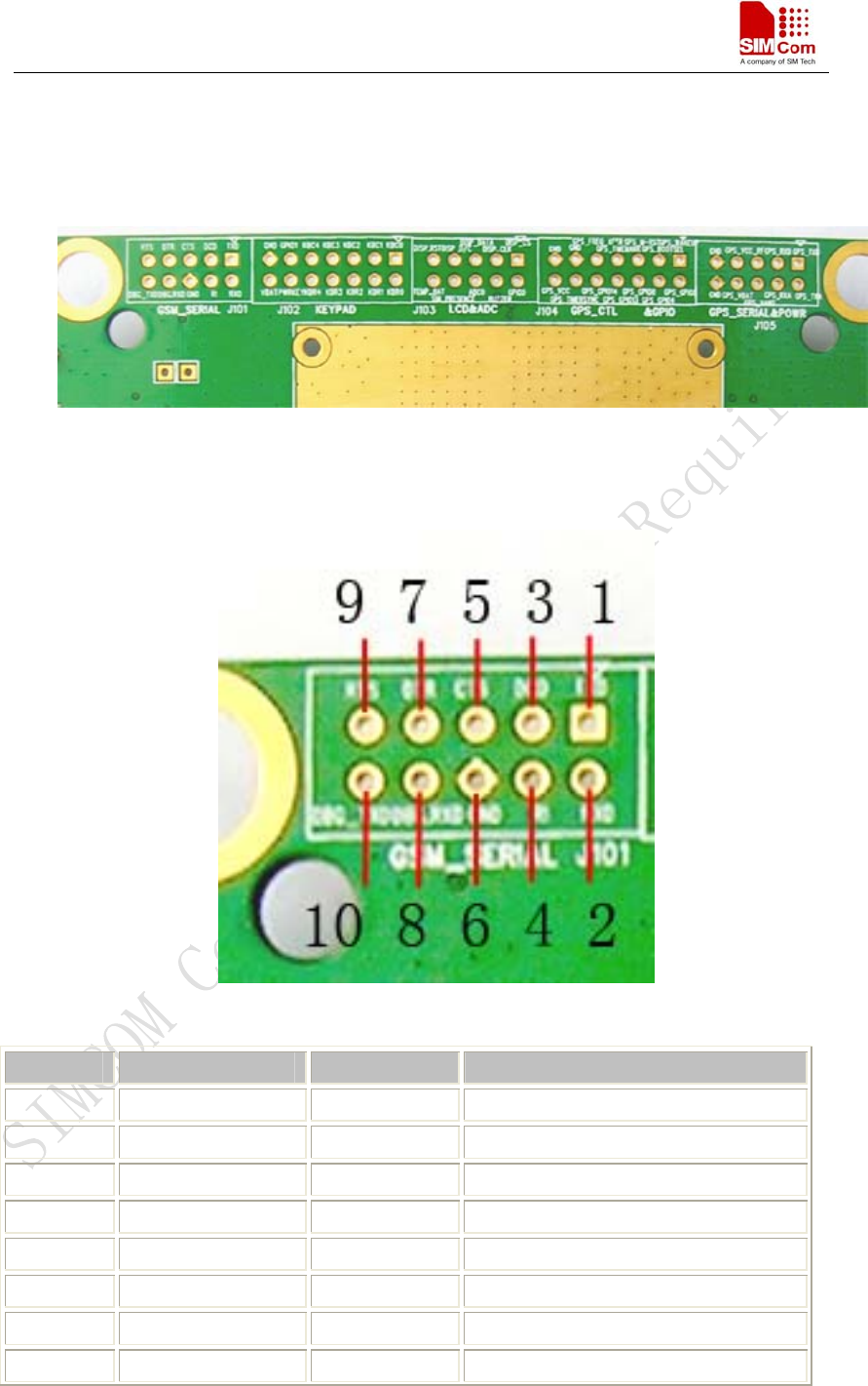
Figure 14: GSM serial ports
Pin Signal I/O Description
1 TXD O Transmit data
2 RXD I Receive data
3 DCD O Data carrier detection
4 RI O Ring Indicator
5 CTS O Clear to Send
6 GND GND
7 DTR I Data Terminal Ready
8 DEBUG_RX I Receive data
SIM548C EVB User Guide
SIM548C-EVB_ UGD _V1.01 04.05.2008
18
9 RTS I Request to Send
10 DEBUG_TX O Transmit data
4.2 LCD & ADC
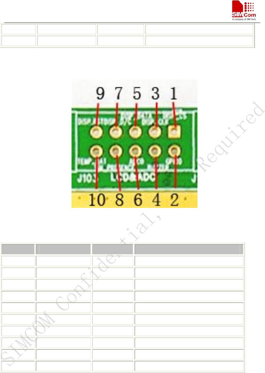
Figure 15: LCD & ADC interface
Pin Signal I/O Description
1 DISP_CS O Display enable output
2 NC
3 DISP_CLK O Display clock output
4 BUZZER O Buzzer output.
5 DISP_DATA I/O Display data line
6 ADC0 I Adc input
7 DISP_D/C O Display data or address select
8 SIM_PRESENCE I SIM Card Detection
9 DISP_RESET O Display reset outplay
10 TEMP_BAT I For measure the batter temperature
SIM548C EVB User Guide
SIM548C-EVB_ UGD _V1.01 04.05.2008
19
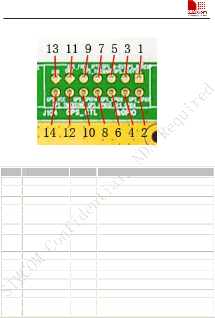
4.3 GPS control & I/O
Figure 16: GPS control & I/O interface
Pin Signal I/O Description
1 GPS_WAKEUP I GPS WAKEUP key
2 NC
3 GPS_BOOTSEL I For re-programming the Flash, it must be set to High
4 NC
5 GPS_MRST I Reset pin of the GPS part, active low.
6 NC
7 GPS_TIMEMARK O 1 PPS timemark output for synchronizing to within
1 microsecond of GPS time.
8 NC
9 NC
10 NC
11 GND GND
12 NC
13 GND GND
14 GPS_VCC I GPS part power supply
SIM548C EVB User Guide
SIM548C-EVB_ UGD _V1.01 04.05.2008
20
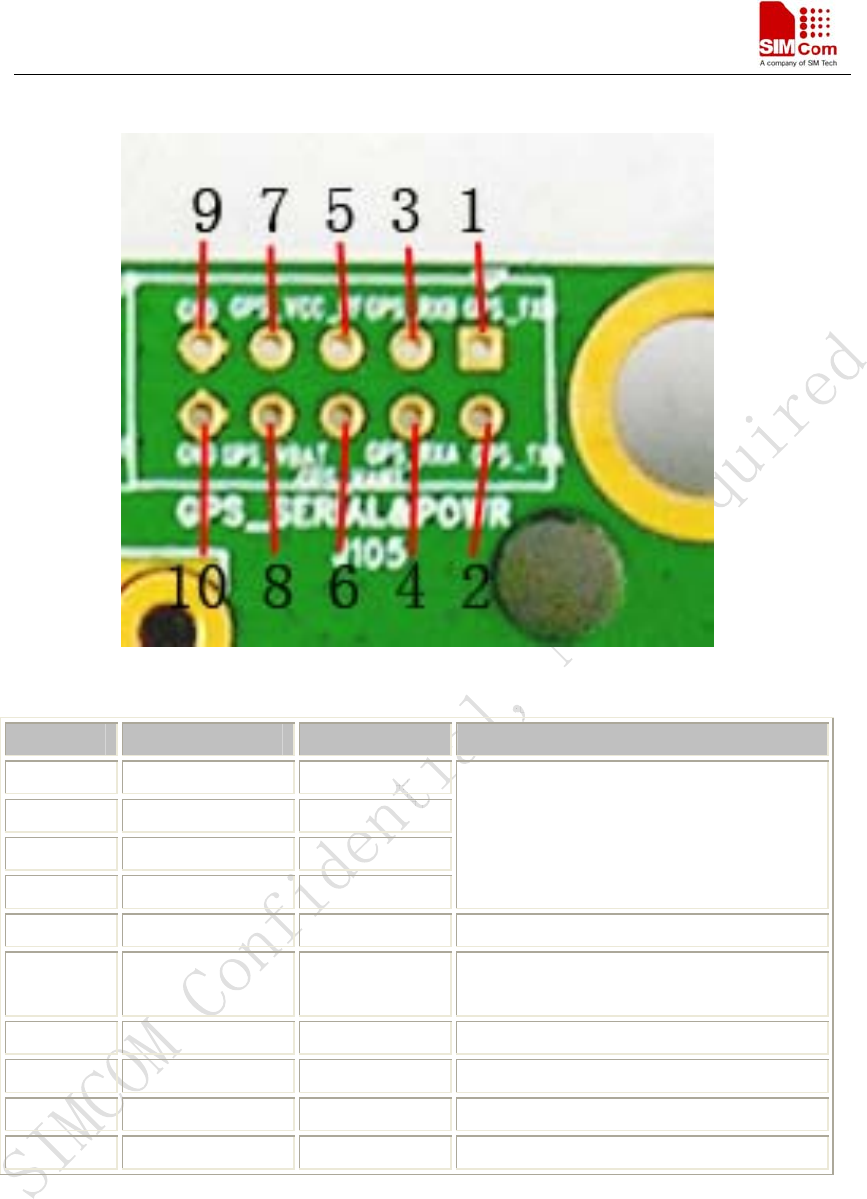
4.5 GPS serial ports and power
Figure 17: GPS serial ports
Pin Signal I/O Description
1 GPS_TXB O
2 GPS_TXA O
3 GPS_RXB I
4 GPS_RXA I
GPS serial interface.
5 GPS_VCC_RF O Power supply for 3V active antenna.
6 GPS_VANT I External DC power supply for an active
antenna.
7 GPS_VCC_RF O Power supply for 3V active antenna.
8 GPS_VRTC I Apply 3V dc for backup RTC & SRAM.
9 GND GND
10 GND GND
SIM548C EVB User Guide
SIM548C-EVB_ UGD _V1.01 04.05.2008
21
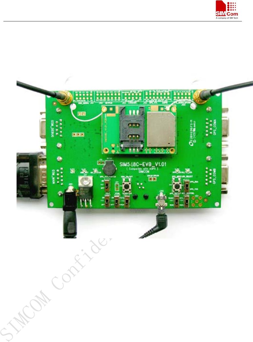
5 EVB and accessory equipment
At normal circumstance, the EVB and its accessory are equipped as the following figure:
Figure 18: EVB and accessory equipment

SIM548C EVB User Guide
SIM548C-EVB_ UGD _V1.01 04.05.2008
22
6 Illustration
6.1 GSM part
6.1.1 Running
(1) Connect the SIM548C module to the 60pins connector on the SIM548C EVB, insert the 5V
direct current source adapter, switch shifter S101 on the RUN state, shifter S102 on the ON
state;
(2) Press the GSM_ON/OFF button Z101 for about 2 seconds , then the GSM part of SIM548C
begins to run.
You will see the light GSM_NET on the EVB glittering at a certain frequency corresponding to
various states, then you can judge whether the EVB and SIM548C is running or not. No function
and test can be executed when we have not connected necessary accessories.
6.1.2 Connecting Net and calling
(1) Connect the serial port line to the GSM_MAIN serial port, open the HyperTerminal (AT
command windows) on your personal computer, the location of the HyperTerminal in
windows2000 is START →accessory→ communication →HyperTerminal. Set the correct
baud rate and COM number. The default baud rate of SIM548C is 115200 bps, and the COM
number based on which port your serial port line insert in, you should select such as COM1,
COM3 or COMx etc.
(2) Connect the GSM antenna to the SIM548C module using an antenna transmit line, insert SIM
card into the SIM card interface, insert headphone or handset into its interface.
(3) Act on the step of running which mentioned above, power on the system, typing the AT
command in the HyperTerminal, and then the SIM548C module will execute its
corresponding function.
6.1.3 Downloading
Connect the serial port line to the GSM_MAIN serial port, connect the direct current source
adapter, run the download program and press the START key, then switch shifter S102 on the ON
state, shifter S101 on the D/L state, then the download procedure is executing
6.1.4 Turn off
Press the GSM_ON/OFF button Z101 for about 1 second, the GSM part of SIM548C will be
SIM548C EVB User Guide
SIM548C-EVB_ UGD _V1.01 04.05.2008
23
turned off.
6.1.5 Charging
Connect the SIM548C module to the 60pin connector interface and the external battery to
charging interface, which have been provided on the EVB. Insert the direct current source adapter;
switch shifter S102 on the OFF state, shifter S105 on the ON state, then the SIM548C will go to
the charging state.
6.2 GPS part
6.1.1 Running:
(1) Connect the module to the 60pins connector on the EVB, insert the 5V direct current source
adapter.
(2) Switch shifter S103 & shifter S104 on the RUN state, shifter S106 on the GPS_TXA state.
(3) Switch shifter S102 & shifter S107 on the ON state, then the GPS part of the module begins to
run.
You will see the GPS indicator (RX/TX_LED) on the EVB glittering at a 1Hz frequency, then you
can judge whether the EVB and the GPS part of the module is running or not. No function and test
can be executed when we have not connected necessary accessories.
Notes:
1.Be sure of both shifter S103 and shifter S104 is on RUN state when the GPS part of SIM548C
is running normally, otherwise the GPS part of the module will be on a undetermined state.
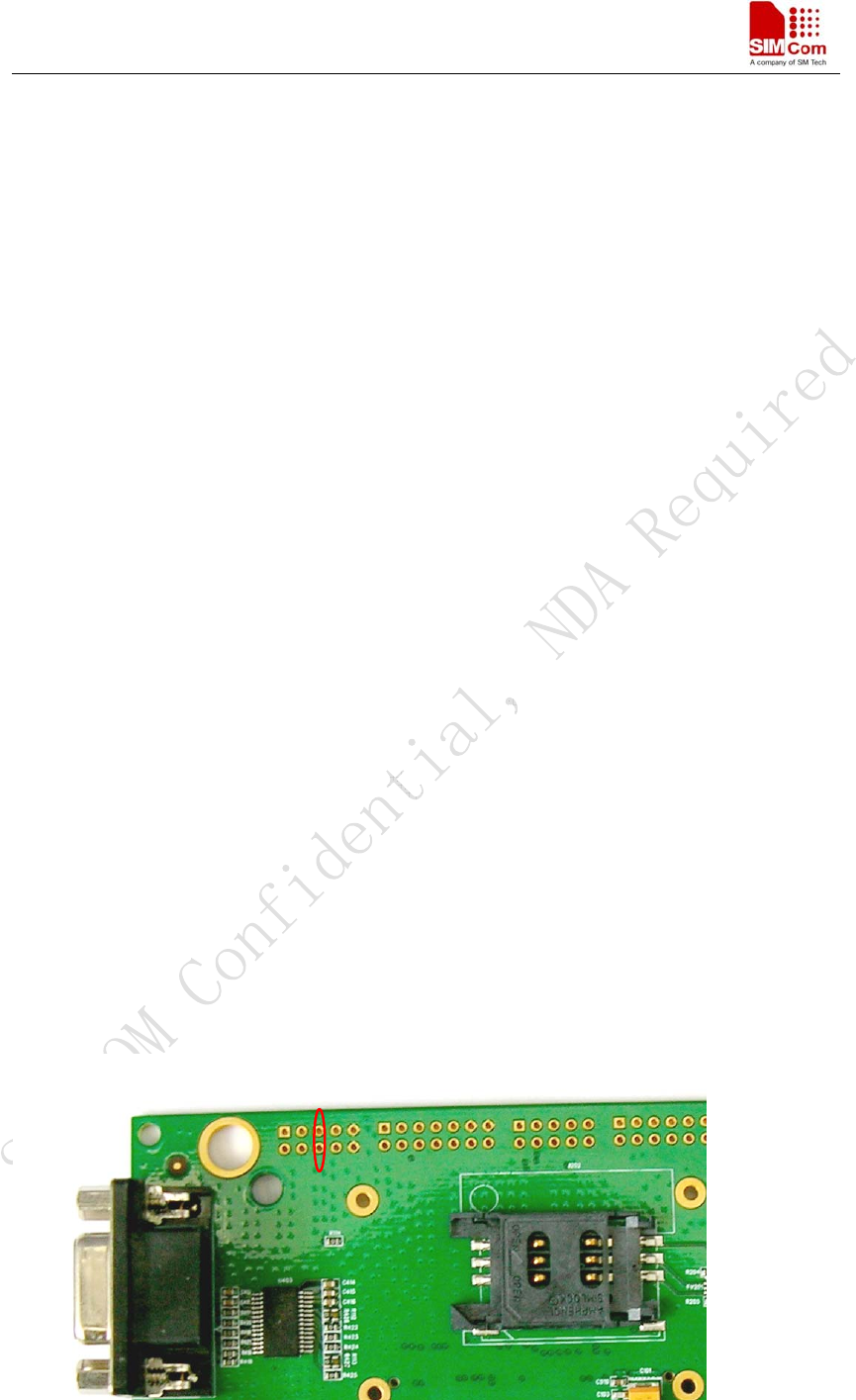
2. There are two types of GPS antenna:
One is active antenna, if the customer uses the active GPS antenna in the SIM548C-EVB kit to
demo GPS, for providing the power to the active GPS antenna, it is necessary to connect
GPS_VANT with GPS_RF_VCC, the picture as below:

SIM548C EVB User Guide
SIM548C-EVB_ UGD _V1.01 04.05.2008
24
The other is passive antenna, if the customer want to use passive GPS antenna to demo GPS,
there is no need to provide power to the antenna.
6.1.2 Tracking the satellite signals
(1) Connect the serial port line to the GPS_COMA serial port
(2) Connect the GPS antenna to the module using an antenna transmit line
(3) Run the GPS part of the module as 6.1.1 described
(4) Then you will see the information transmitted by the GPS_COMA serial port in our demo tool
or through Hyper Terminal (AT Command widow)
6.1.3 Downloading
(1) Connect the serial port line to the GPS_COMA serial port,.
(2) Connect the direct current source adapter
(3) Switch shifter S103 on RUN state and shifter S104 on the D/L state
(4) Switch shifter S102 on the ON state and shifter S106 on the GPS_RXA state. (See note)
(5) Switch shifter S107 on the ON state
(6) Run the download program and press the execute key, and then the download procedure is
executing immediately.
Note: Step (4) is only for the judgement while program downloading form the PC side by the
glittering of the LED on EVB board, if you don’t need this visual indication or you can judge by
the response of the download program on the PC side directly, you can jump to step (5) directly
。
6.1.4 Turn off and Reset
(1) Turn off: Switch shifter S107 on the OFF state, that will cut the power supply for the GPS part
directly, and then the GPS part of the module will be turned off immediately.
(2) Reset: Press the button Z102 and release it lightly, the GPS part of the module will reset
immediately, it’s necessary when system is running on a emergent state or encountering a
unpredictable malfunction and so on .

Contact us:
Shanghai SIMCom Wireless Solutions Ltd.
Add: SIM Technology Building, No. 700, Yishan Road, Shanghai,P. R. China 200233
Tel: +86 21 5427 8900
Fax: +86 21 5427 6035
URL: www.sim.com/wm/