Simcom 2013060301 GSM/GPRS/EDGE/UMTS/HSDPA Terminal with GPS function User Manual users manual
Shanghai Simcom Ltd. GSM/GPRS/EDGE/UMTS/HSDPA Terminal with GPS function users manual
Simcom >
users manual
T5320+G_User Guide_V1.01
Smart Machine Smart Decision
T5320+G_User Guide_V1.01 2 2013-04-15
Document Title T5320+G User Guide
Version 1.01
Date 2013-04-15
Status Release
Document Control ID T5320+G User Guide V1.01
General Notes
SIMCom offers this information as a service to its customers, to support application and engineering efforts that
use the products designed by SIMCom. The information provided is based upon requirements specifically
provided to SIMCom by the customers. SIMCom has not undertaken any independent search for additional
relevant information, including any information that may be in the customer’s possession. Furthermore, system
validation of this product designed by SIMCom within a larger electronic system remains the responsibility of the
customer or the customer’s system integrator. All specifications supplied herein are subject to change.
Copyright
This document contains proprietary technical information which is the property of SIMCom Limited, copying of
this document and giving it to others and the using or communication of the contents thereof, are forbidden
without express authority. Offenders are liable to the payment of damages. All rights reserved in the event of grant
of a patent or the registration of a utility model or design. All specification supplied herein are subject to change
without notice at any time.
This device complies with part 15B of the FCC rules. Operation is subject to the following two conditions:
(1) this device may not cause harmful interference
(2) this device must accept any interference, including interference that may cause undesired operation.
WARNING: Changes or modifications to this unit not expressly approved by the party responsible for compliance
could void the user's authorityto operate the equipment.
Copyright © Shanghai SIMCom Wireless Solutions Ltd. 2013

Smart Machine Smart Decision
T5320+G_User Guide_V1.01 3 2013-04-15
Contents
Contents.............................................................................................................................................................................3
Version History.................................................................................................................................................................7
1 Introduction ...............................................................................................................................................................8
2 Key features ...............................................................................................................................................................9
3 Terminal dimensions...............................................................................................................................................10
4 Installation ............................................................................................................................................................... 11
5 Interface introduction .............................................................................................................................................12
5.1 Overview......................................................................................................................................................... 12
5.2 T5320+G Functional Diagram........................................................................................................................ 13
5.3 Accessory information.................................................................................................................................... 14
6 Application Interface...............................................................................................................................................15
6.1 Power Supply..................................................................................................................................................15
6.2 Serial Interface................................................................................................................................................ 16
6.3 10 PIN I/O interface........................................................................................................................................ 17
6.3.1 Audio interface............................................................................................................................................ 19
6.3.2 ADC channel ............................................................................................................................................... 20
6.3.3 GPIO interfaces ........................................................................................................................................... 21
6.4 LED indicator ................................................................................................................................................. 22
6.5 Micro USB interface....................................................................................................................................... 23
6.6 USIM Card Interface ...................................................................................................................................... 24
6.7 I2C Interface ................................................................................................................................................... 25
6.8 GPS Interface.................................................................................................................................................. 26
6.8.1 Technical specification................................................................................................................................ 26
6.8.2 Antenna type ............................................................................................................................................... 26
6.8.3 GPS operating ............................................................................................................................................. 27
6.9 Antenna interface............................................................................................................................................ 27
6.9.1 Antenna connector....................................................................................................................................... 27
6.9.2 Antenna type ............................................................................................................................................... 28
6.9.3 Antenna placement...................................................................................................................................... 28
7 Electrical, Reliability and Radio Characteristics..................................................................................................29
7.1 Absolute Maximum Ratings ........................................................................................................................... 29
7.2 Recommended Operating Conditions ............................................................................................................. 29
7.3 Electro-Static Discharge ................................................................................................................................. 29
7.4 Operating frequency ....................................................................................................................................... 30
7.5 Transmitter output power and receiver sensitivity.......................................................................................... 30
8 Software/ Firmware Upgrade.................................................................................................................................31
8.1 Tool introduction ............................................................................................................................................ 31
8.2 Illustration of software updating..................................................................................................................... 31
Appendix .........................................................................................................................................................................35
A. Related Documents .................................................................................................................................................. 35
B. Terms and Abbreviations .......................................................................................................................................... 36


Smart Machine Smart Decision
T5320+G_User Guide_V1.01 5 2013-04-15
Table Index
TABLE 1: T5320+G SERIES FREQUENCY BANDS...................................................................................................... 8
TABLE 2: T5320+G KEY FEATURES ............................................................................................................................. 9
TABLE 3: THE POWER LINE ASSIGNMENT.............................................................................................................. 15
TABLE 4: 9-POLE D-SUB (FEMALE) RS-232.............................................................................................................. 16
TABLE 5: SIGNAL ASSIGNMENT OF 10 PIN CABLE ............................................................................................... 18
TABLE 6: MIC INPUT CHARACTERISTICS ............................................................................................................... 19
TABLE 7: SPEAKER OUTPUT CHARACTERISTICS ................................................................................................. 19
TABLE 8: AUDIO PARAMETER ................................................................................................................................... 20
TABLE 9: ADC SPECIFICATION .................................................................................................................................. 20
TABLE 10: AT+CADC READ ADC................................................................................................................................21
TABLE 11: T5320+G GPIOS........................................................................................................................................... 22
TABLE 12: STATUS OF THE NETLIGHT INDICATOR (GREEN).............................................................................. 22
TABLE 13: AT+CUSBSPD SWITCH T5320+G USB HIGH OR FULL SPEED ........................................................ 23
TABLE 14: AT+CRIIC READ VALUES FROM REGISTER OF IIC DEVICE .......................................................... 25
TABLE 15: AT+CWIIC WRITE VALUES TO REGISTER OF IIC DEVICE ............................................................. 25
TABLE 16: ANTENNA CHOOSING CONSIDERATION.............................................................................................. 26
TABLE 17: ANTENNA CHOOSING CONSIDERATION.............................................................................................. 28
TABLE 18: ABSOLUTE MAXIMUM RATINGS........................................................................................................... 29
TABLE 19: RECOMMENDED OPERATING CONDITIONS ....................................................................................... 29
TABLE 20: THE ESD CHARACTERISTICS (TEMPERATURE: 25℃, HUMIDITY: 45 %) ....................................... 29
TABLE 21: OPERATING FREQUENCY........................................................................................................................ 30
TABLE 22: TRANSMITTER OUTPUT POWER AND RECEIVER SENSITIVITY .................................................... 30
TABLE 23: RELATED DOCUMENTS ........................................................................................................................... 35
TABLE 24: TERMS AND ABBREVIATIONS................................................................................................................ 36
TABLE 25: SAFETY CAUTION..................................................................................................................................... 37

Smart Machine Smart Decision
T5320+G_User Guide_V1.01 6 2013-04-15
Figure Index
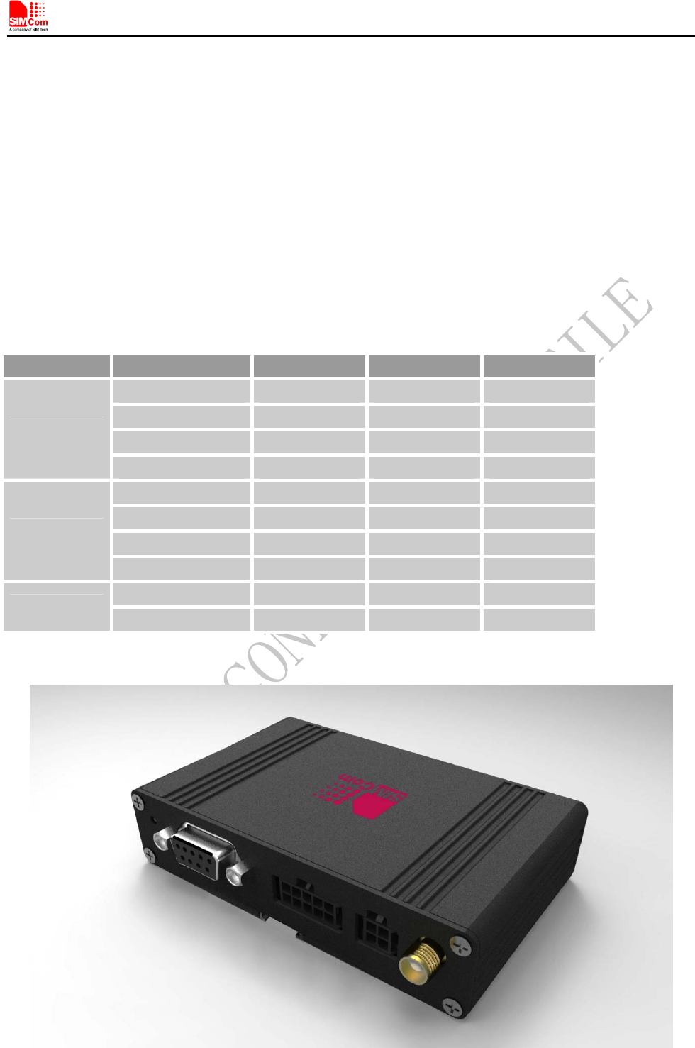
FIGURE 1: T5320+G OVERVIEW ................................................................................................................................... 8
FIGURE 2: MECHANICAL DIMENSIONS OF T5320+G(UNIT: MM).................................................................. 11
FIGURE 3: INSTALLATION OF THE TERMINAL ...................................................................................................... 12
FIGURE 4: T5320+G INTERFACE FRONT VIEW ....................................................................................................... 13
FIGURE 5: T5320+G INTERFACE BACK VIEW ......................................................................................................... 13
FIGURE 6: T5320+G FUNCTIONAL DIAGRAM ......................................................................................................... 14
FIGURE 8: DIMENSIONS OF POWER LINE(UNIT: MM)..................................................................................... 15
FIGURE 9: POWER INTERFACE .................................................................................................................................. 16
FIGURE 10: PIN ASSIGNMENT RS-232 (D-SUB 9-POLE FEMALE) ........................................................................ 16
FIGURE 11: COM PORT PROPERTIES OF THE HYPER TERMINAL....................................................................... 17
FIGURE 12: SIGNAL ASSIGNMENT OF 10PIN I/O PORT ......................................................................................... 18
FIGURE 13: DIMENSIONS OF 10-LINE CABLE......................................................................................................... 18
FIGURE 14: SPEAKER REFERENCE CIRCUIT .......................................................................................................... 19
FIGURE 15: INDICATOR LED....................................................................................................................................... 22
FIGURE 16: MICRO USB INTERFACE ........................................................................................................................ 23
FIGURE 17: INSTALLATION OF SIM CARD .............................................................................................................. 25
FIGURE 18: ANTENNA INTERFACE ........................................................................................................................... 28
FIGURE 19: VIRTUAL PORTS IN COMPUTER MANAGER WINDOW........................................................................ 31
FIGURE 20: QDL WINDOW .......................................................................................................................................... 31
FIGURE 21: BROWSE THE SOURCE FILE ................................................................................................................. 32
FIGURE 22: CLICK DOWNLOAD BUTTON WITHOUT POWER UP ....................................................................... 32
FIGURE 23: UPGRADE IN PROCEEDING................................................................................................................... 33
FIGURE 24: FINISH UPGRADING ............................................................................................................................... 33
Smart Machine Smart Decision
T5320+G_User Guide_V1.01 7 2013-04-15
Version History
Date Version Description of change Author
2013-04-15 1.01 Origin Libing
Smart Machine Smart Decision
1 Introduction
This document describes features, functions and interfaces of T5320+G terminal in great detail.
T5320+G is a quad-band GSM/GPRS/EDGE and dual-band UMTS /HSDPA that works on frequencies of GSM
850MHz, EGSM 900 MHz, DCS 1800 MHz, PCS 1900MHz and WCDMA 2100/900MHz, 2100/850 MHz or
1900/850MHz, which is a ideal solution for wireless m2m applications, the terminal features HSDPA Category
5/6 -3.6 Mbps.
With the help of this document user can understand T5320+G interface specifications, electrical and mechanical
quickly.
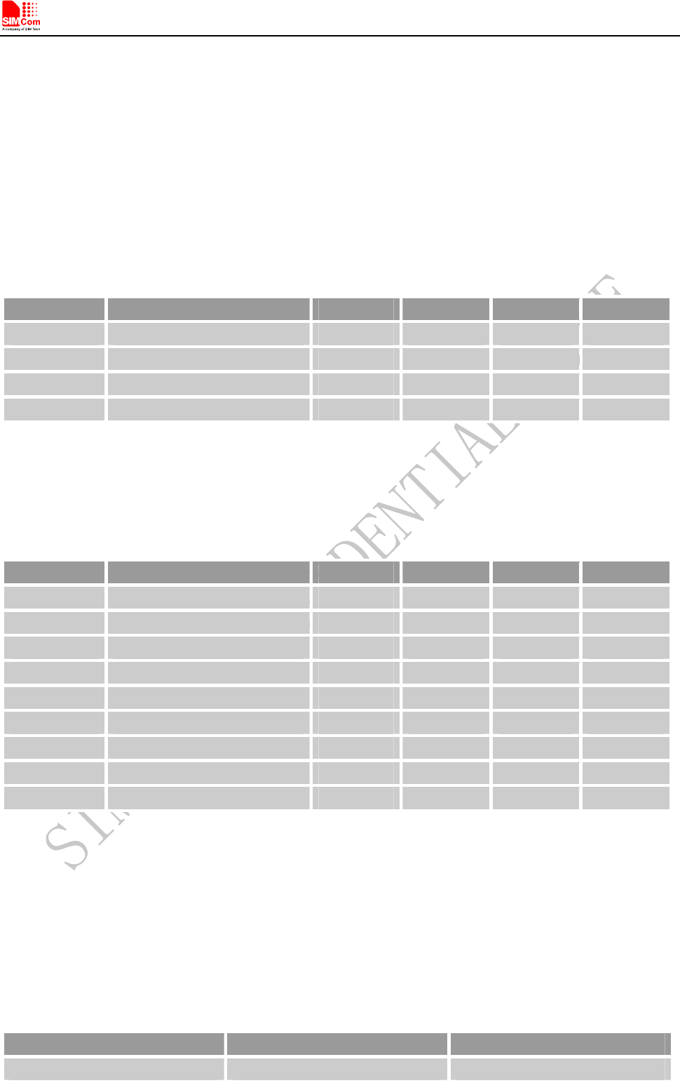
Table 1: T5320+G series frequency bands
Standard Frequency T5320E+G T5320J+G T5320A+G
GSM 850MHz 3 3 3
EGSM 900MHz 3 3 3
DCS1800MHz 3 3 3
GSM
PCS1900MHz 3 3 3
WCDMA 850MHz 3 3
WCDMA 900MHz 3
WCDMA 1900MHz 3
WCDMA
WCDMA 2100MHz 3 3
HSDPA 3 3 3
HSPA
HSUPA
Figure 1: T5320+G overview
T5320+G_User Guide_V1.01 8 2013-04-15

Smart Machine Smart Decision
T5320+G_User Guide_V1.01 9 2013-04-15
2 Key features
T5320+G terminal terminal has the following features:
1. Standard AT commands set
2. SIMCom proprietary AT commands set
3. watch-dog function
4. Short circuit protection
5. Voice call
6. GPIOs
7. ADC function
8. GPS
Table 2: T5320+G key features
Feature Implementation
Power supply 5V ~ 30V
Transmission data
● Dual-mode UMTS/HSDPA/EDGE/GPRS operation
● GPRS Class B, multislot class 12 operation, Supports coding scheme: CS1-4
● EDGE multislot class 12 operation, Supports coding schemes MSC1-9
● UMTS R99 data rates-384 kbps DL/UL
● HSDPA Category 5/6 -3.6 Mbps and Category12-1.8 Mbps
● Integrate the TCP/IP protocol
Transmitting power
z Class 4 (+33dBm) for GSM850 and EGSM900
z Class 1 (+30dBm) for DCS 1800 PCS GSM1900
z Class 3 (+24dBm) for WCDMA 2100, WCDMA FDD BDI
z Class 3 (+24dBm) for WCDMA 1900, WCDMA FDD BDII
z Class 3 (+24dBm) for WCDMA 900, WCDMA FDD BDVIII
z Class 3 (+24dBm) for WCDMA 850, WCDMA FDD BDV
GPS
● Mobile-Assisted mode
● Mobile-based mode
● Standalone mode
Temperature range
z Normal operation: -30°C ~ +75°C
z Restricted operation: -35°C ~ -30°C and +75 °C ~ +80°C*
z Storage temperature -40°C ~ +85°C
CSD z CSD feature: 9.6, 14.4, 64 kbps UL/DL
SMS
● MT, MO, CB, Text and PDU mode
● SMS storage: SIM card
● Support transmission of SMS alternatively over CSD or GPRS. User can
choose preferred mode.
FAX Group 3 Class 1
USIM interface Support USIM card: 1.8V, 3V
External antenna SMA type RF connector
Audio features Speech codec modes:
● Half Rate (ETS 06.20)
Smart Machine Smart Decision
● Full Rate (ETS 06.10)
● Enhanced Full Rate (ETS 06.50 / 06.60 / 06.80)
● AMR (WCDMA)
● AMR+QCP (GSM)
● A5/1, A5/2, and A5/3 ciphering
USB Support USB2.0 Slave mode
RS232 serial port
Serial port:
z Full modem interface with status and control lines, unbalanced,
asynchronous.
z 1200bps to 115200bps.
z Default rate is 115200bps.
z Can be used for AT commands data stream.
z Support RTS/CTS hardware handshake and software ON/OFF flow control.
z Multiplex ability according to GSM 07.10 Multiplexer Protocol.
Phonebook management Support phonebook types: SM, FD, LD, RC, ON, MC.
SIM application toolkit Support SAT class 3, GSM 11.14 Release 98
Support USAT
Physical characteristics Size: 98*60*23mm
Weight: 129g
Firmware upgrade Firmware upgradeable by USB interface
*T5320+G does work at this temperature, but some radio frequency characteristics may deviate from the GSM specification.
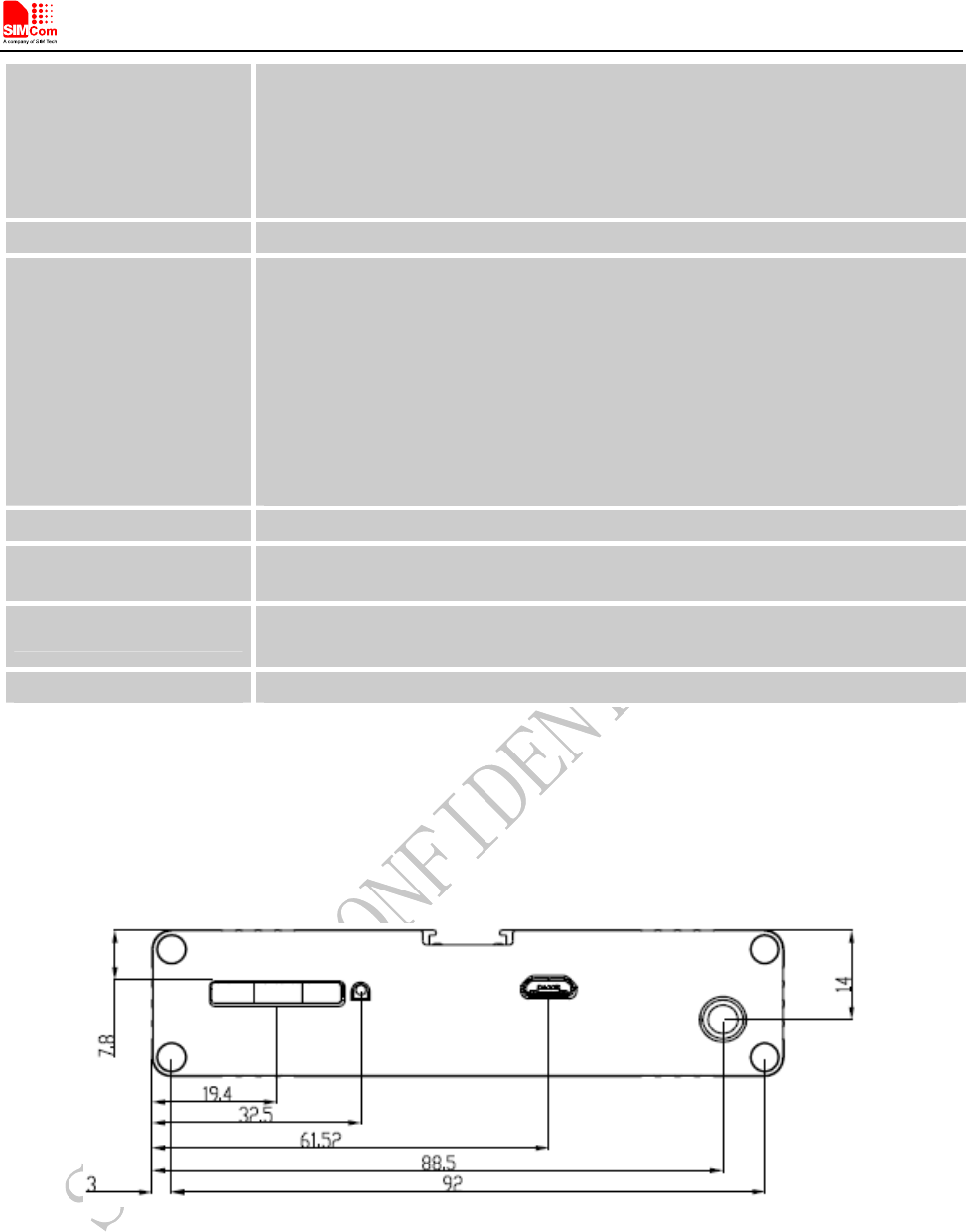
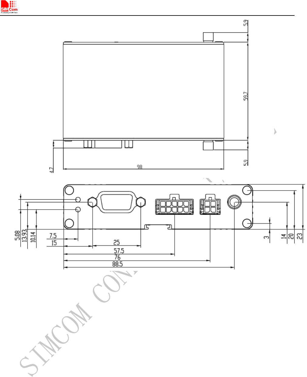
3 Terminal dimensions
T5320+G_User Guide_V1.01 10 2013-04-15
Smart Machine Smart Decision
Figure 2: Mechanical dimensions of T5320+G(Unit: mm)
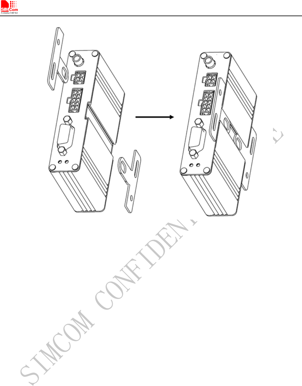
4 Installation
The terminal can be fixed by two kickstands (Optional) that provided by SIMCom, the following figure is the
illustration.
T5320+G_User Guide_V1.01 11 2013-04-15
Smart Machine Smart Decision
Figure 3: Installation of the terminal
5 Interface introduction
5.1 Overview
T5320+G Terminal provides the following connectors for power supply, GPIOs, Audio, ADC, Serial port and
antenna:
z The GSM/WCDMA antenna interface(SMA type female connector)
z The 4 PIN I/O port for power supply
z The 10 PIN I/O port for audio, I2C, GPIOs and ADC
z The standard RS232 interface
z LED indicator for power (Red) and GSM/WCDMA netlight (Green)
z USIM card holder
z Micro USB interface
z The GPS antenna interface(SMA type female connector)
T5320+G_User Guide_V1.01 12 2013-04-15
Smart Machine Smart Decision
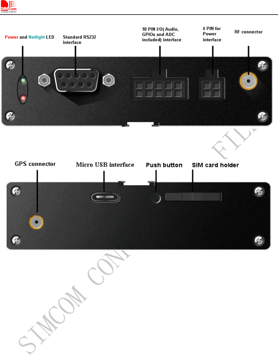
T5320+G_User Guide_V1.01 13 2013-04-15
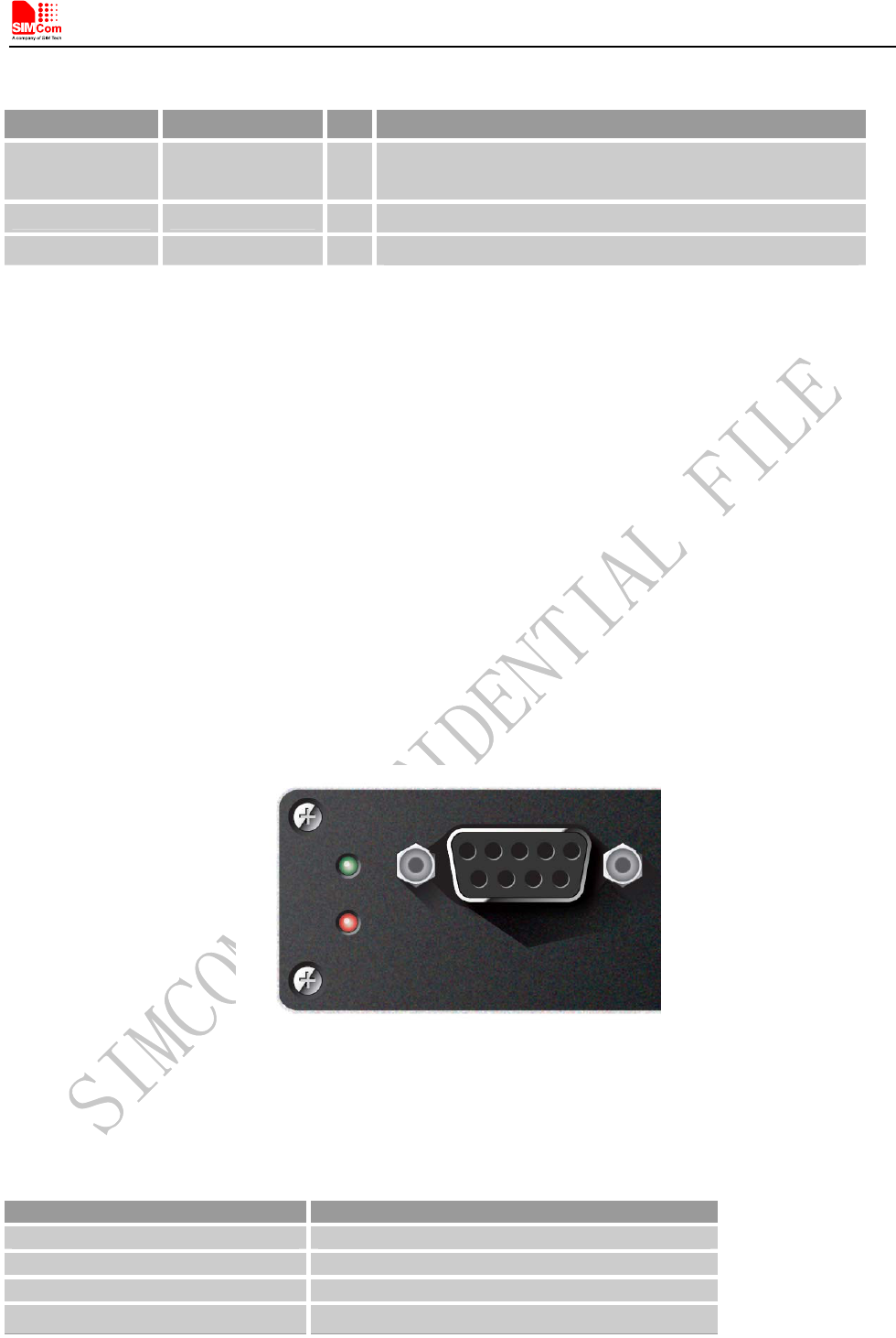
Figure 4: T5320+G interface Front view
Figure 5: T5320+G interface Back view
Note: For the I/O interface, SIMCom provides 4-line cable and 10-line cable (optional) to assist developers, it
will be introduced at the following chapter.
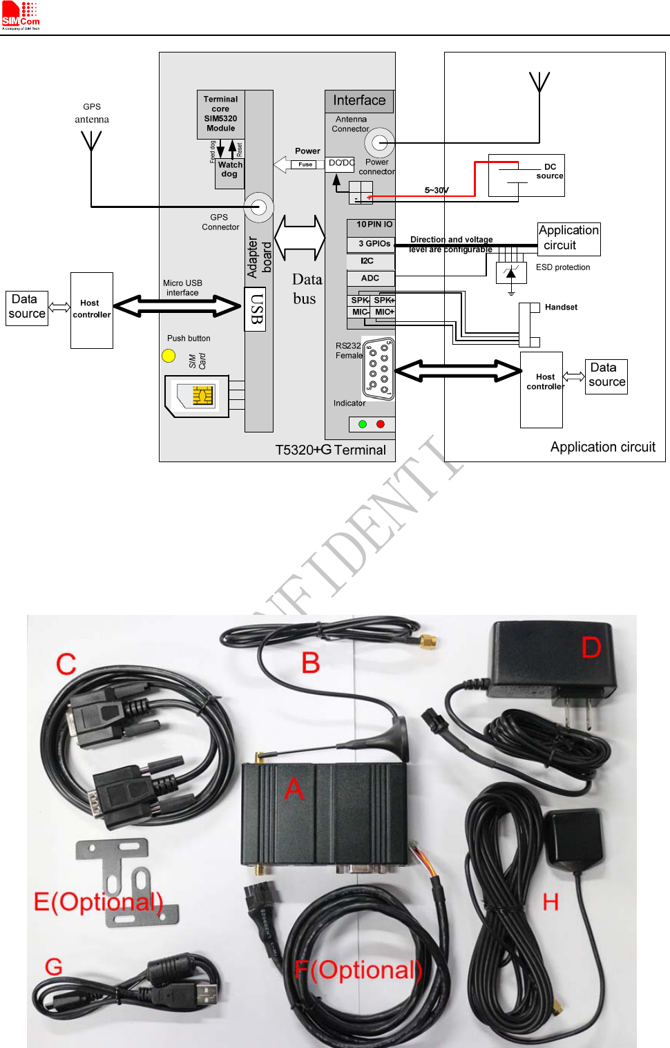
5.2 T5320+G Functional Diagram
The following figure shows a functional diagram of T5320+G and typical accessories.
Smart Machine Smart Decision
T5320+G_User Guide_V1.01 14 2013-04-15
Figure 6: T5320+G functional diagram
5.3 Accessory information
Smart Machine Smart Decision
A: T5320+G Terminal
B: WCDMA/GSM Antenna
C: Male to Female DB9 Line
D: 5V Adapter
E: Two kickstands (Optional)
F: 10-Line cable (Optional)
G: Micro-USB cable
H: GPS Antenna
6 Application Interface
6.1 Power Supply
Customer can use the DC adapter that SIMCom provides as the power source.
If customer does not use the adapter, then DC source should be satisfied with the following requirements.
z Input voltage range 5-30V
z Normal voltage 12V
z Current ability 1A
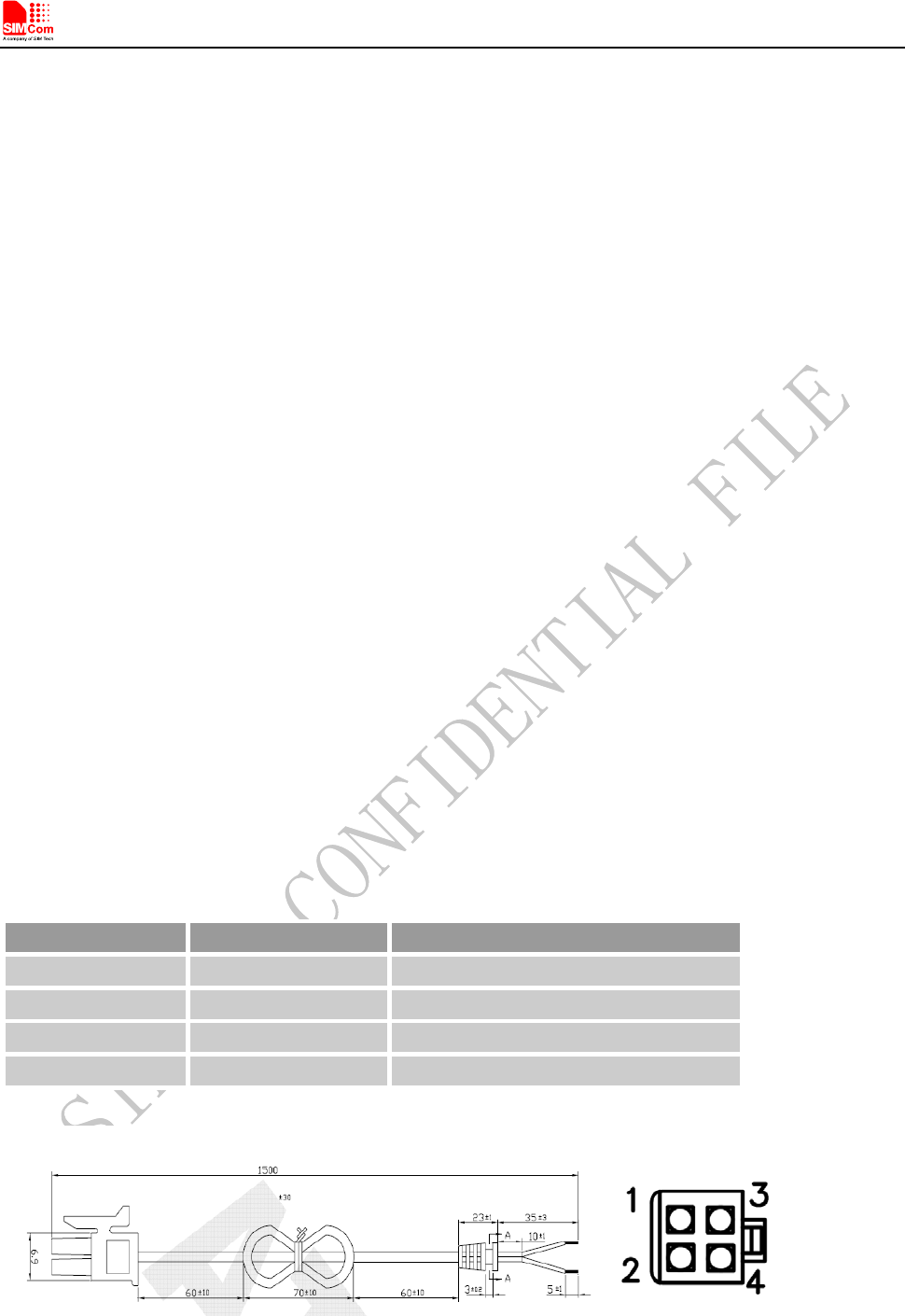
The following chapter introduces the power line that SIMCom provides to customers, customer can power the
terminal by connect the terminal to the DC source via this line.
The power line includes four lines as the following figure shows, and table 2 gives a detailed description.
NOTE
:
The part number of power line connector is ATOM GROUP LIMITED ATOM010070190003 in
T5320+G side. User can login http://www.asia-atom.com/en/ for more information.
Table 3: The power line assignment
PIN Number Colour Item
1 white GPIO2
2 Red Power
3 Yellow GPIO3
4 Black Ground
Figure 7: dimensions of power line(Unit: mm)
T5320+G_User Guide_V1.01 15 2013-04-15
Smart Machine Smart Decision
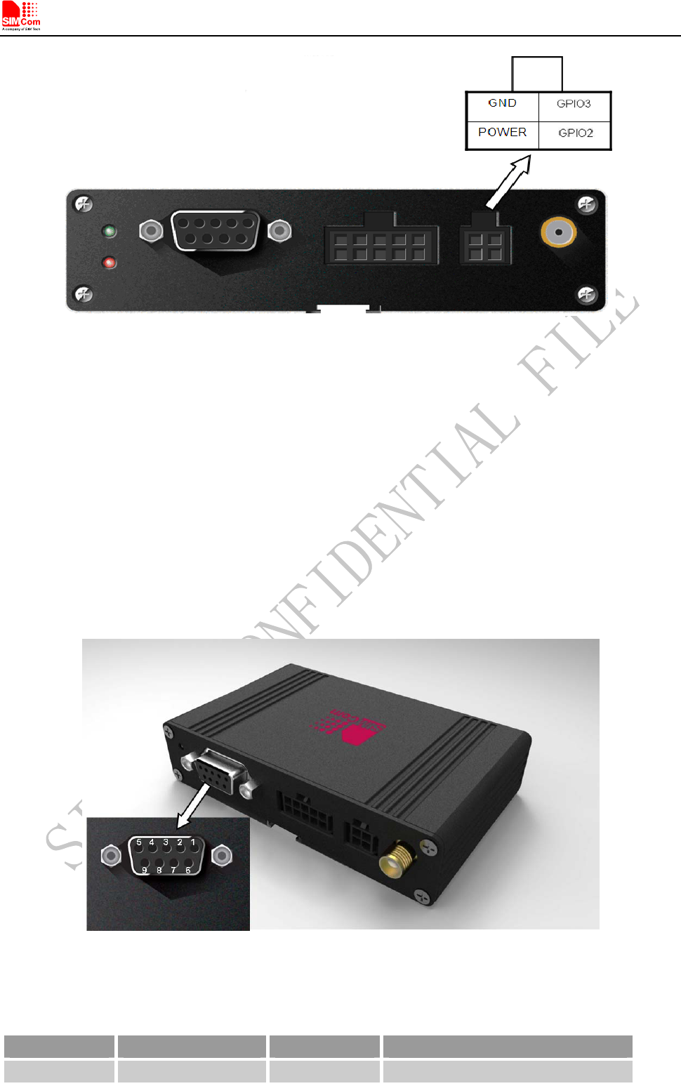
Figure 8: Power interface
When a valid power appears the terminal will power up automatic, for the MCU that inside the terminal processed
the power up part, MCU also acts as a Watch Dog, when the terminal runs wrong, MCU will cut off the power
and recover it immediately to restart the terminal.
6.2 Serial Interface
T5320+G provides one asynchronous RS232 serial port (female).The RS232 standard interface serves to connect
a PC, Data Terminal Equipment (DTE) or other application, which acts as host controller of the T5320+G
Terminal with all its functions. Through the RS232 interface it can be used as GSM/GPRS modem for sending
and receiving of SMS, Data and Fax calls.
Figure 9: Pin assignment RS-232 (D-Sub 9-pole female)
Table 4: 9-pole D-Sub (female) RS-232
Pin no Signal name I/O Function
1 DCD O Data Carrier Detected
T5320+G_User Guide_V1.01 16 2013-04-15
Smart Machine Smart Decision
2 RXD O Receive Data
3 TXD I Transmit Data
4 DTR I Data Terminal Ready
Attention: The ignition of T5320+G
Terminal is activated via a rising
edge of high potential (+3 ... +15 V)
5 GND
- Ground
6 DSR O Data Set Ready
7 RTS
I Request To Send
8 CTS O Clear To Send
9 RING O Ring Indication
Note: User can use AT command “AT+IPR=x” to set a fixed baud rate and the setting will be saved to
non-volatile flash memory automatically. After the configuration is set as fixed baud rate, the URC such as
"RDY", "+CFUN: 1" and "+CPIN: READY” will be reported when T5320+G is powered on.
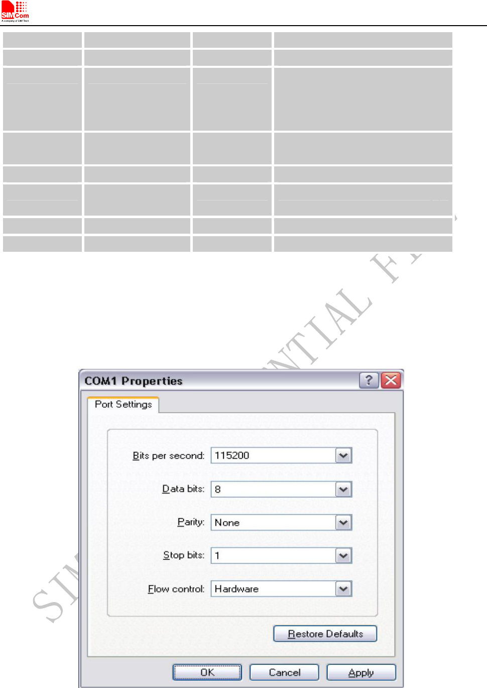
Hyper terminal usually as the PC software tool to operate T5320+G; customer can set up a connection between
PC and terminal, configure the port properties as the figure 9 shows.
Figure 10: COM port properties of the hyper terminal
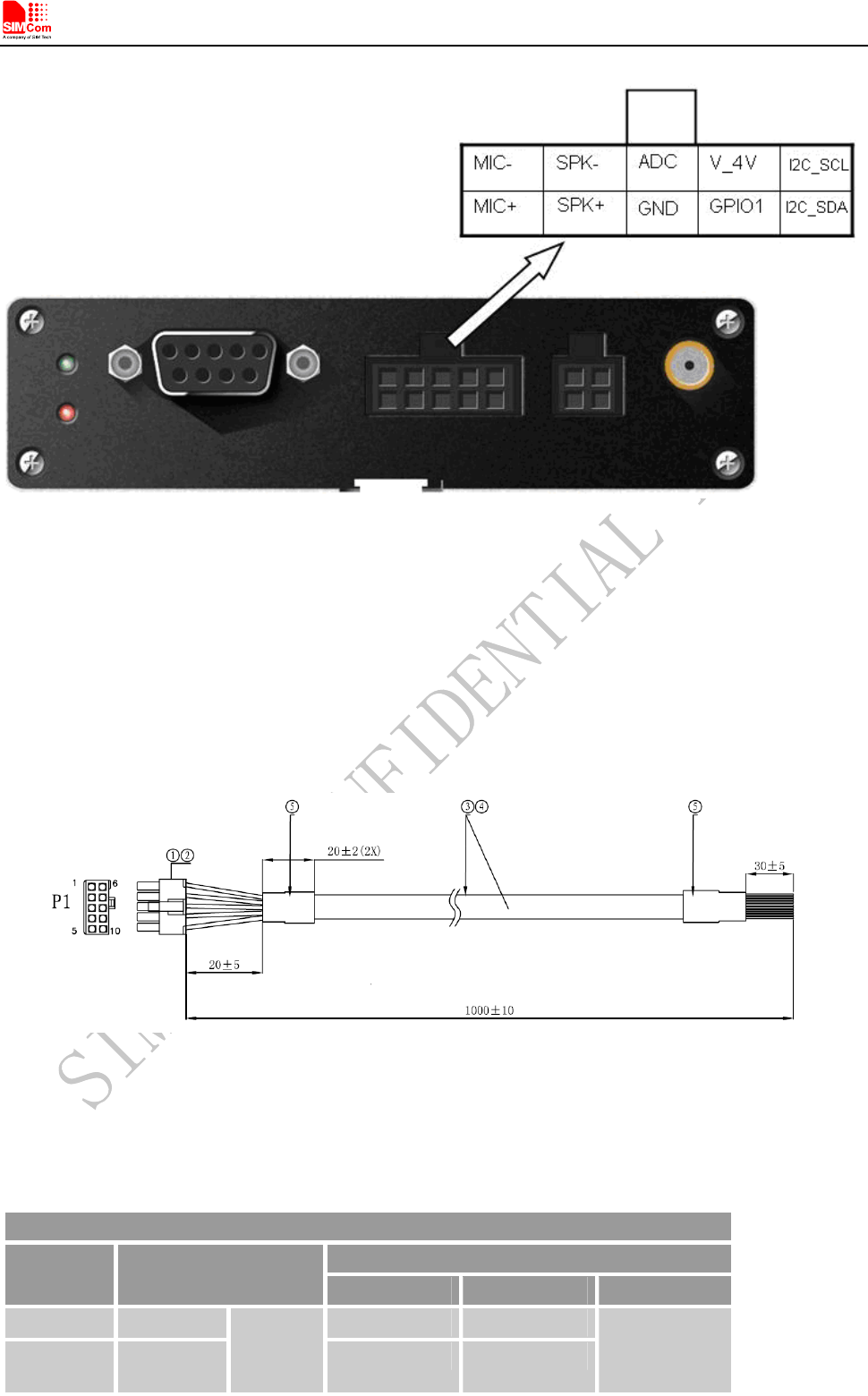
6.3 10 PIN I/O interface
T5320+G_User Guide_V1.01 17 2013-04-15
T5320+G provides a 10 PIN I/O interface for customer use, including Audio, GPIOs and 1 ADC channel.
Smart Machine Smart Decision
The following figure gives a brief view of signal assignment.
Figure 11: signal assignment of 10PIN I/O port
NOTE
:
The part number of the 10 PIN I/O connector is ATOM GROUP LIMITED ATOM010070190005 in
T5320+G side. User can login http://www.asia-atom.com/en/ for more information.
To make the usage conveniently, SIMCom provides a cable for customer, it can be inserted to the 10 PIN I/O port
so customer can develop their application by connecting some devices.
Figure 11 shows the specification of cable.
Figure 12: Dimensions of 10-line cable
Table 5: signal assignment of 10 pin cable
Connecting diagram
Terminal signal
P1 Wire color and cutting
length Signal name I/O Command
1 Green I2C_SDA I/O
2 Yellow
GPIO1 I/O
Configurable
by AT
commands
T5320+G_User Guide_V1.01 18 2013-04-15
Smart Machine Smart Decision
3 Black GND Ground
4 Orange SPK+ O
5 Brown MIC+ I
6 White I2C_SCL I/O Configurable
by AT
commands
7 Gray V_4V DC OUT
8 Red ADC I
9 Purple SPK- O
10 Blue
1007 26#
MIC- I
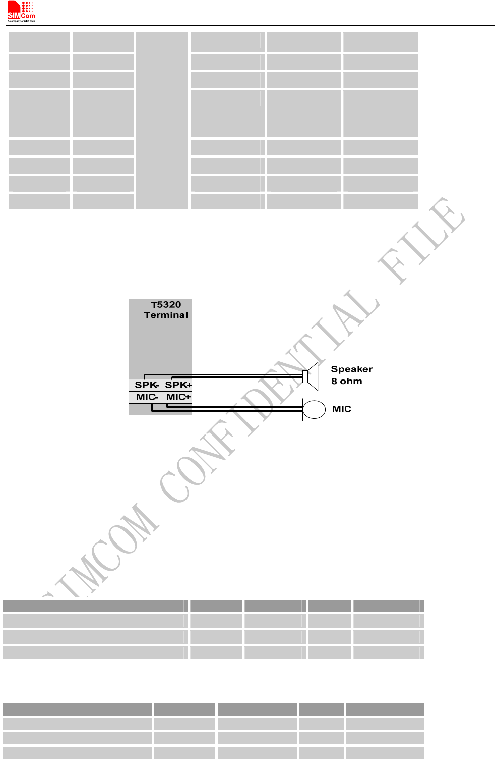
6.3.1 Audio interface
T5320+G has one pair of audio input and audio output; it can be connected to a speakerphone directly.
Figure 13: Speaker reference circuit
Firstly, customer must use the “AT +CSDVC=3” to select speaker audio channel.
Customer can set the terminal MIC gain level to make the sounds louder so that the listener can hear more clearly.
And if the sound a little lower on the terminal side, customer can use the “AT +CLVL” to make the sound higher
so that customer can hear clearly.
The AT commands should be send to the terminal by RS232 or USB interface, and the following table shows the
detail commands.
Table 6: MIC input characteristics
Parameter Min Typ Max Unit
Working Voltage - 1.8 - V
Working Current 0.07 0.4 1 mA
External Microphone Load Resistance 1.2 2.2 k Ohms
Table 7: Speaker output characteristics
Parameter Min Typ Max Unit
Quiescent Current - 2.5 4 mA
Load resistance - 8 - Ohm
Output power(1KHz) - 500 - mW
T5320+G_User Guide_V1.01 19 2013-04-15
Smart Machine Smart Decision
T5320+G_User Guide_V1.01 20 2013-04-15
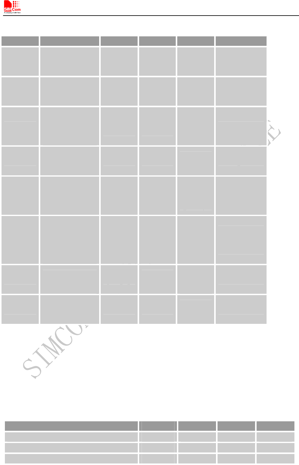
Table 8: Audio parameter
Parameter Influence to Range Gain range Calculation AT command
micAmp1
MICP/MICN
analogue amplifier
gain before ADC
0…1 0…24dB 2 steps AT+CMICAMP1
txVol Digital gain of input
signal after ADC
0,
1...65535
Mute,
-84...+12dB
20 * log
(txVol/
16384)
AT+CTXVOL
txGain
Digital gain of input
signal after
summation of
sidetone
0,
1...65535
Mute,
-84...+12dB
20 * log
(txGain/
16384)
AT+CTXGAIN
txFilter
Input PCM 13-tap
filter parameters, 7
values
0...65535 --- MATLAB
calculate AT+CTXFTR
rxGain
Digital gain of
output signal after
summation of
sidetone
0,
1...65535
Mute,
-84...+12dB
20 * log
(rxGain/
16384)
AT+CRXGAIN
rxVol
Digital Volume of
output signal after
speech decoder,
before summation of
sidetone and DAC
-300…300 dbm -300…300d
bm
AT+CLVL
AT+CVLVL
AT+CRXVOL
stGain Digital attenuation
of sidetone 0, 1...65535 Mute,
-96...0dB
20 * log
(stGain/
16384) -12
AT+SIDET
rxFilter
Output PCM 13-tap
filter parameters, 7
values
0...65535 --- MATLAB
calculate AT+CRXFTR
Please refer to document [1] and document [3] for details.
6.3.2 ADC channel
T5320+G provides an auxiliary ADC, which can be used to measure the voltage. User can use AT command
“AT+CADC=2” to read the voltage value.
Table 9: ADC specification
Parameter Min Typ Max Unit
Voltage range 0 - 2.2 V
ADC Resolution - 12 - Bits
Sampling rate - - 200K Hz
Note: the maximum voltage that the ADC can gather is 2.2V
Smart Machine Smart Decision
T5320+G_User Guide_V1.01 21 2013-04-15
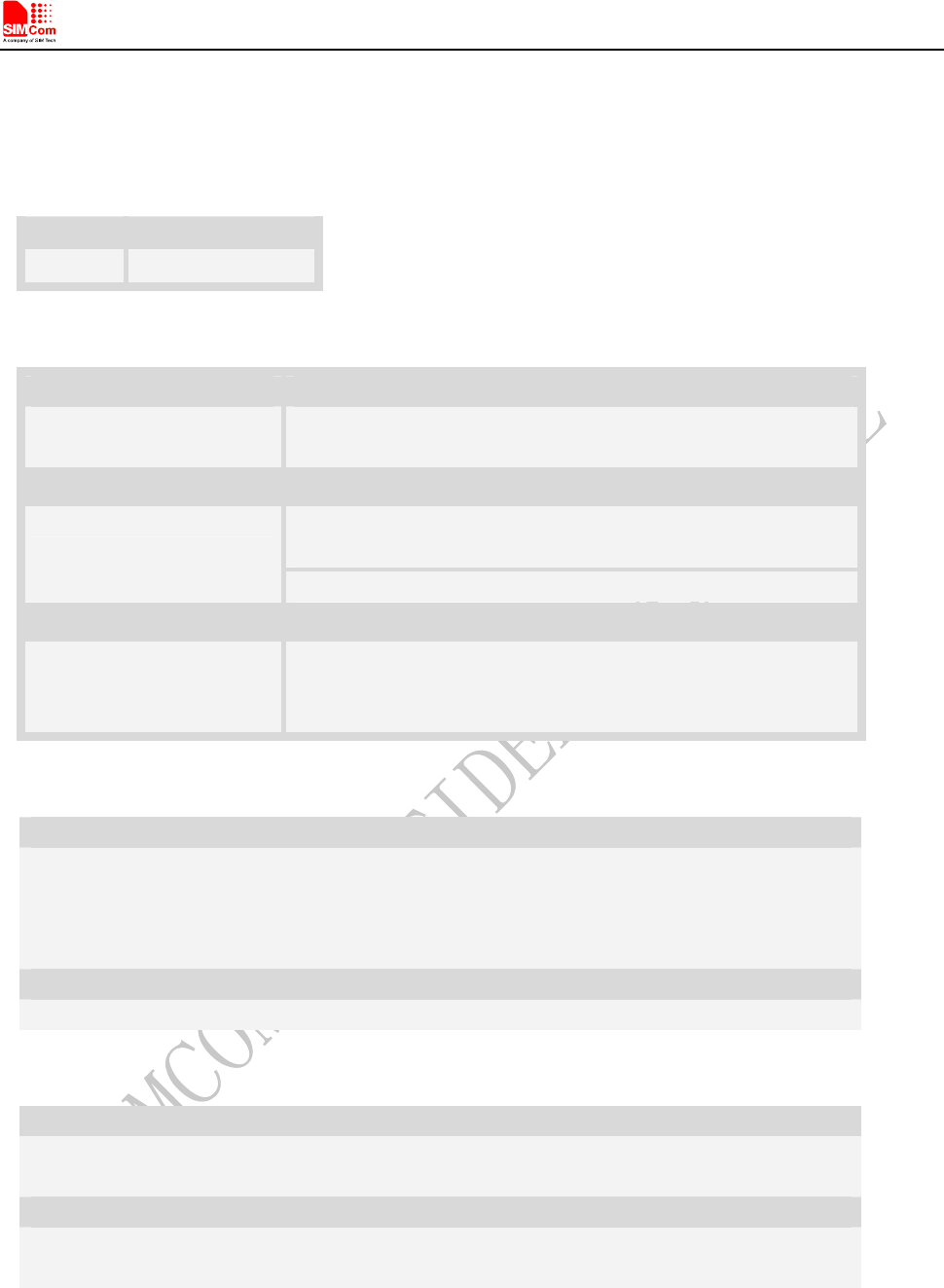
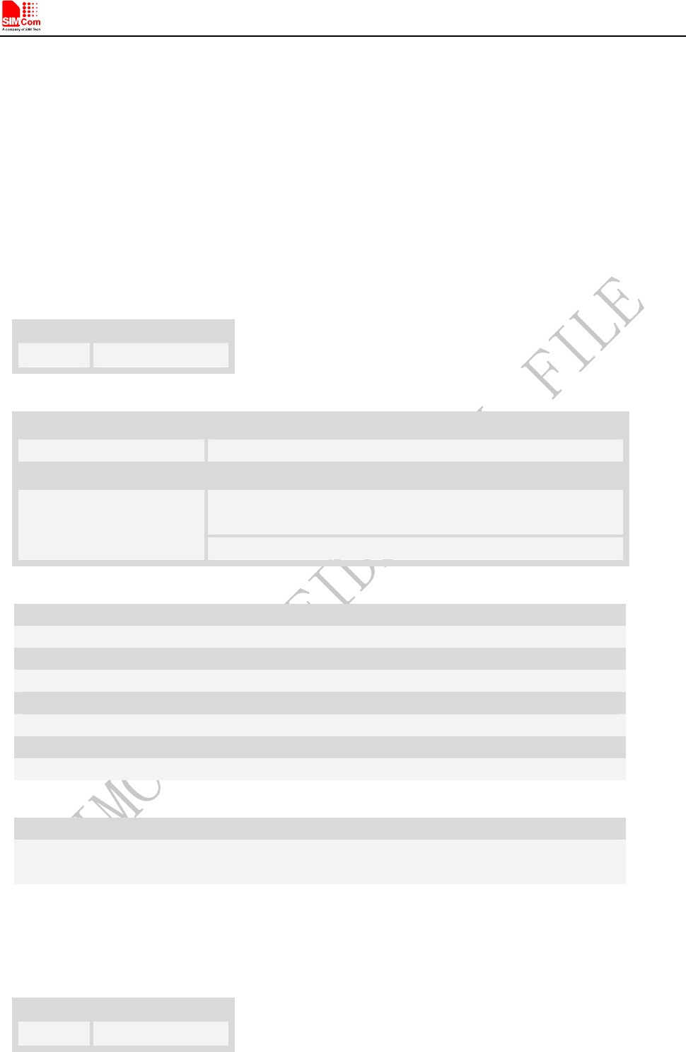
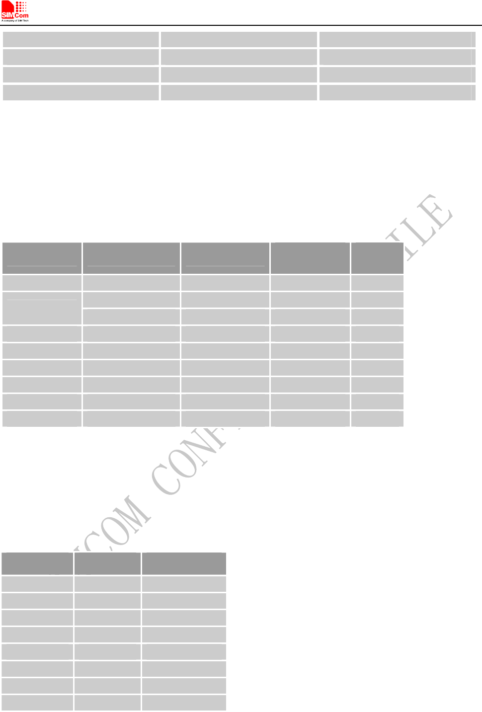
Table 10: AT+CADC Read ADC
Description
Read the ADC value from modem. We support 3 type of ADC, raw type, temperature type and voltage type.
SIM PIN References
NO Vendor
Syntax
Test Command Responses
AT+CADC=? +CADC: (range of supported <adc>s)
OK
Write Command Responses
+CADC: <value>
OK
AT+CADC=<adc>
ERROR
Execution Command Responses
AT+CADC Same as AT+CADC= 0:
+CADC: <value>
OK
Defined values
<adc>
ADC type:
0 – raw type.
1 – temperature type.
2 – voltage type(mv)
<value>
Integer type value of the ADC.
Examples
AT+CADC=?
+CADC:(0-2)
OK
AT+CADC=0
+CADC: 187
OK
6.3.3 GPIO interfaces
T5320+G provides 3 GPIO pins. All GPIOs can be configured as inputs or outputs. User can use AT Commands
to read or write GPIOs status. Refer to document [1] for details.
Smart Machine Smart Decision
Table 11: T5320+G GPIOs
T5320+G GPIO CPU Pin No. I/O Function
GPIO1 GPIO0 I/O General input/output PIN. It can be used as wake/interrupt
signal to host from module If it is unused, left open.
GPIO2 GPIO2 I/O General input/output PIN.
GPIO3 GPIO3 I/O General input/output PIN.
Example 1: If user use T5320+G GPIO1 pin as an output GPIO:
1) AT+CGDRT=0,1 //set T5320+G GPIO1 to output
2) AT+CGSETV=0,1 //set T5320+G GPIO1 to high value
Example 2: If user use T5320+G GPIO4 pin as an input GPIO:
1) AT+CGDRT=5,0 //set T5320+G GPIO4 to input
Please refer to document [1] and document [2] for details.
6.4 LED indicator
A red led indicates the power status, when a valid power appears, the red led will lighten up. But a lighten up red
led does not mean that the terminal has been powered up.
A green led indicates the terminal status and GSM net status, after the terminal been powered up and registered to
the network, it will blink at a certain frequency.
Figure 14: Indicator LED
Table 12: Status of the NETLIGHT indicator (Green)
LED Status T5320+G behavior
Always On Searching Network/Call Connect
200ms ON, 200ms OFF Data Transmit
800ms ON, 800ms OFF Registered network
Off Power off / Sleep
T5320+G_User Guide_V1.01 22 2013-04-15
Smart Machine Smart Decision
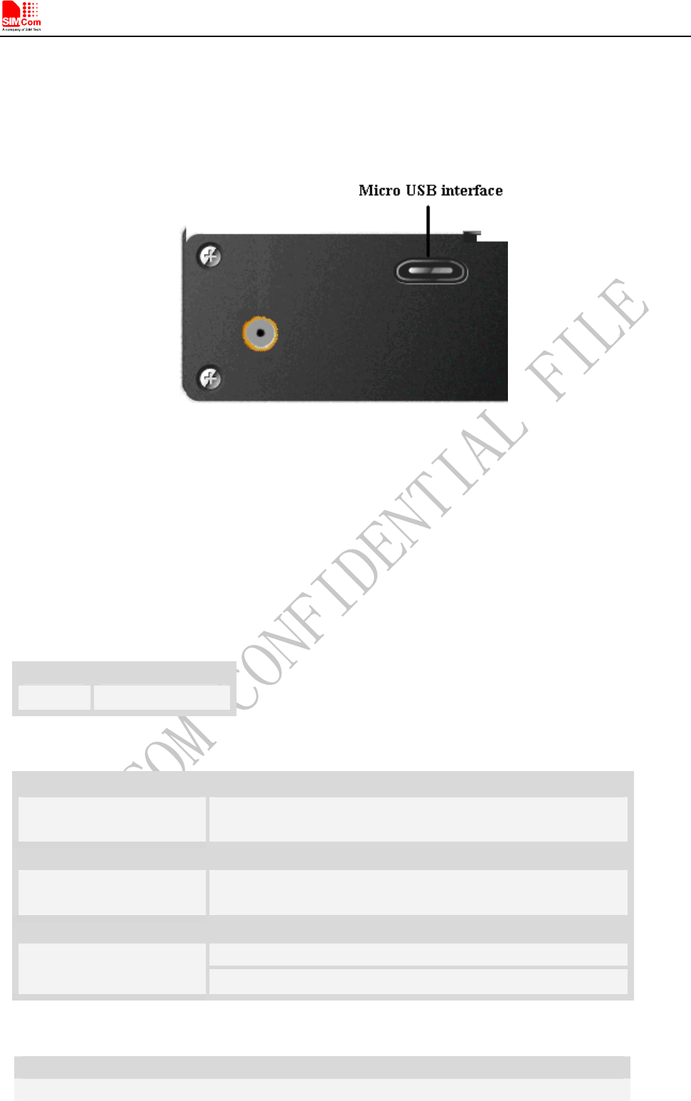
6.5 Micro USB interface
T5320+G provides a Micro USB interface. This interface is compliant with the USB2.0 specification. The
USB2.0 specification requires hosts such as the computer to support full-speed (12Mbps) and high-speed
(480Mbps). USB charging and USB-OTG is not supported.
Figure 15: Micro USB interface
Table 13: AT+CUSBSPD Switch T5320+G USB high or full speed
Description
This command is used to switch the speed of USB between high speed and full speed. If you just want to use full
speed to simplify the circuit then you can use this command to switch the USB speed. This command will save your
configuration so if you don’t change the speed the module will use the latest configuration forever.
This command will only takes effect on the next start-up.
SIM PIN References
NO Vendor
Syntax
Test Command Responses
AT+CUSBSPD=? +CUSBSPD: (list of supported <speed>s)
OK
Read Command Responses
AT+CUSBSPD? +CUSBSPD: <speed>
OK
Write Command Responses
OK
AT+CUSBSPD=<speed>
ERROR
Defined values
<speed>
Integer type and nonvolatile value.
T5320+G_User Guide_V1.01 23 2013-04-15
Smart Machine Smart Decision
T5320+G_User Guide_V1.01 24 2013-04-15
0 – High speed
1 – Full speed (default value)
Examples
AT+CUSBSPD=?
+CUSBSPD: (0-1)
OK
AT+CUSBSPD=0
OK
AT+CUSBSPD=1
OK
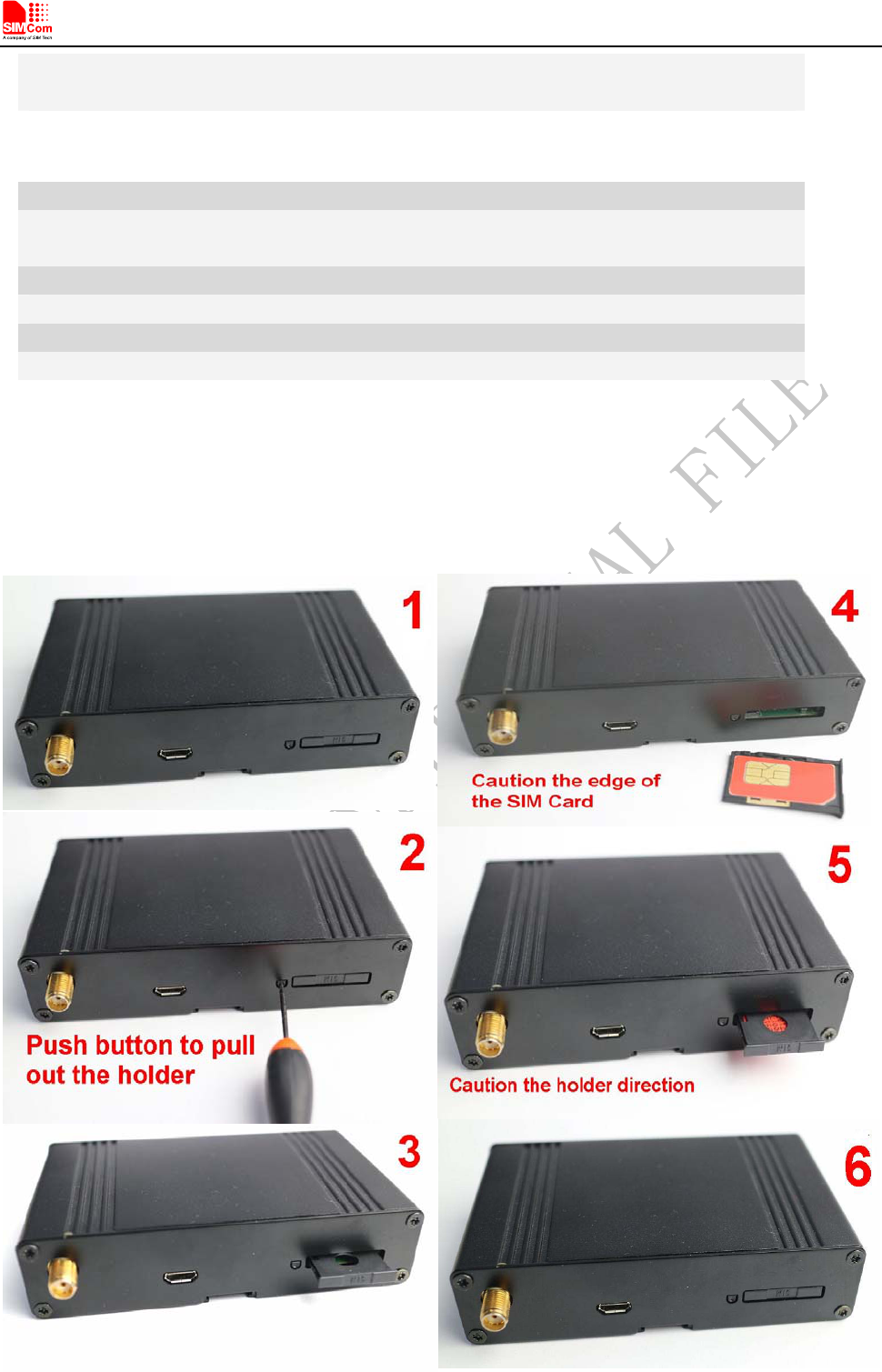
6.6 USIM Card Interface
The USIM provides the required subscription verification information to allow the mobile equipment to attach to a
GSM or UMTS network. Both 1.8V and 3.0V SIM Cards are supported.
T5320+G does not support USIM card “hot” plug.
Smart Machine Smart Decision
T5320+G_User Guide_V1.01 25 2013-04-15
Figure 16: Installation of SIM Card
6.7 I2C Interface
T5320+G provides a I2C interface. I2C is used to communicate with peripheral equipments and can be operated
as either a transmitter or receiver, depending on the device function. Use AT Commands “AT+CRIIC and
AT+CWIIC” to read/write register values of related peripheral equipments connected with I2C interface.
Table 14: AT+CRIIC Read values from register of IIC device
Description
Read values from register of IIC device.
SIM PIN References
NO Vendor
Syntax
Test Command Responses
AT+CRIIC=? OK
Write Command Responses
+CRIIC: <data>
OK
AT+CRIIC=
<addr>,<reg>,<len>
ERROR
Defined values
<addr>
Device address. Input format must be hex, such as 0xFF.
<reg>
Register address. Input format must be hex, such as 0xFF.
<len>
Read length. Range:1-4; unit:byte.
<data>
Data read. Input format must be hex, such as 0xFF – 0xFFFFFFFF.
Examples
AT+CRIIC=0x0F, 0x0F, 2
+CRIIC: FFFF
OK
Table 15: AT+CWIIC Write values to register of IIC device
Description
Write values to register of IIC device.
SIM PIN References
NO Vendor
Syntax

Smart Machine Smart Decision
T5320+G_User Guide_V1.01 26 2013-04-15
Test Command Responses
AT+CWIIC=? OK
Write Command Responses
OK AT+CWIIC=
<addr>,<reg>,<data>,<len> ERROR
Defined values
<addr>
Device address. Input format must be hex, such as 0xFF.
<reg>
Register address. Input format must be hex, such as 0xFF.
<len>
Read length. Range: 1-4; unit: byte.
<data>
Data written. Input format must be hex, such as 0xFF – 0xFFFFFFFF.
Examples
AT+CWIIC=0x0F, 0x0F, 0x1234, 2
+CWIIC: 0x1234
OK
6.8 GPS Interface
T5320+G supports both A-GPS and S-GPS, and then provides three operating modes: mobile-assisted mode,
mobile-based mode and standalone mode. A-GPS includes mobile-assisted and mobile-based mode.
6.8.1 Technical specification
Tracking sensitivity -157 dBm
Cold-start sensitivity -144 dBm
Accuracy (Open Sky) <2m (CEP50)
TTFF (Open Sky) Hot start <1s Cold start 35s(good signal)/ 100s(weak signal)
Receiver Type 16-channel, GPS L1 Frequency (1575.42MHz), C/A Code
Update rate Default 1 Hz
GPS data format NMEA-0183
GPS antenna Passive/Active antenna
6.8.2 Antenna type
.The recommended antenna specifications are showed in following table:
Table 16: antenna choosing consideration
Smart Machine Smart Decision
T5320+G_User Guide_V1.01 27 2013-04-15
Patch
Center Frequency 1575.42MHz
Bandwidth(10db return loss) 10MHZ min.
Polarization R.H.C.P
LNA(for Active antenna)
Center Frequency 1575.42MHz
VSWR ≤2.0
Gain 27db typ.
Voltage DC 3.3*0.6 V
6.8.3 GPS operating
The DC3V voltage for active antenna is controlled by GPIO43.
Passive antenna
If user use passive antenna, The DC3V voltage must be cut off by GPIO43.
1) AT+CGFUNC=12,0 //set T5320+G GPIO43 to general GPIO
2) AT+CGDRT=43,1 //set T5320+G GPIO43 to output
3) AT+CGSETV=43,0 //set T5320+G GPIO43 to low value
4) AT+CGPS=1,1 // start GPS, standalone mode
Active antenna
If user use active antenna, The DC3V voltage must be exist for active antenna.
1) AT+CGFUNC=12,0 //set T5320+G GPIO43 to general GPIO
2) AT+CGDRT=43,1 //set T5320+G GPIO43 to output
3) AT+CGSETV=43,1 //set T5320+G GPIO43 to high value
4) AT+CGPS=1,1 // start GPS, standalone mode
Please refer to document [1] and document [23] for details.
6.9 Antenna interface
6.9.1 Antenna connector
Antenna connector allows transmission of radio frequency (RF) signals between the modem and the external
supplied antenna. The T5320+G modem is fitted with a 50Ω male SMA connector.
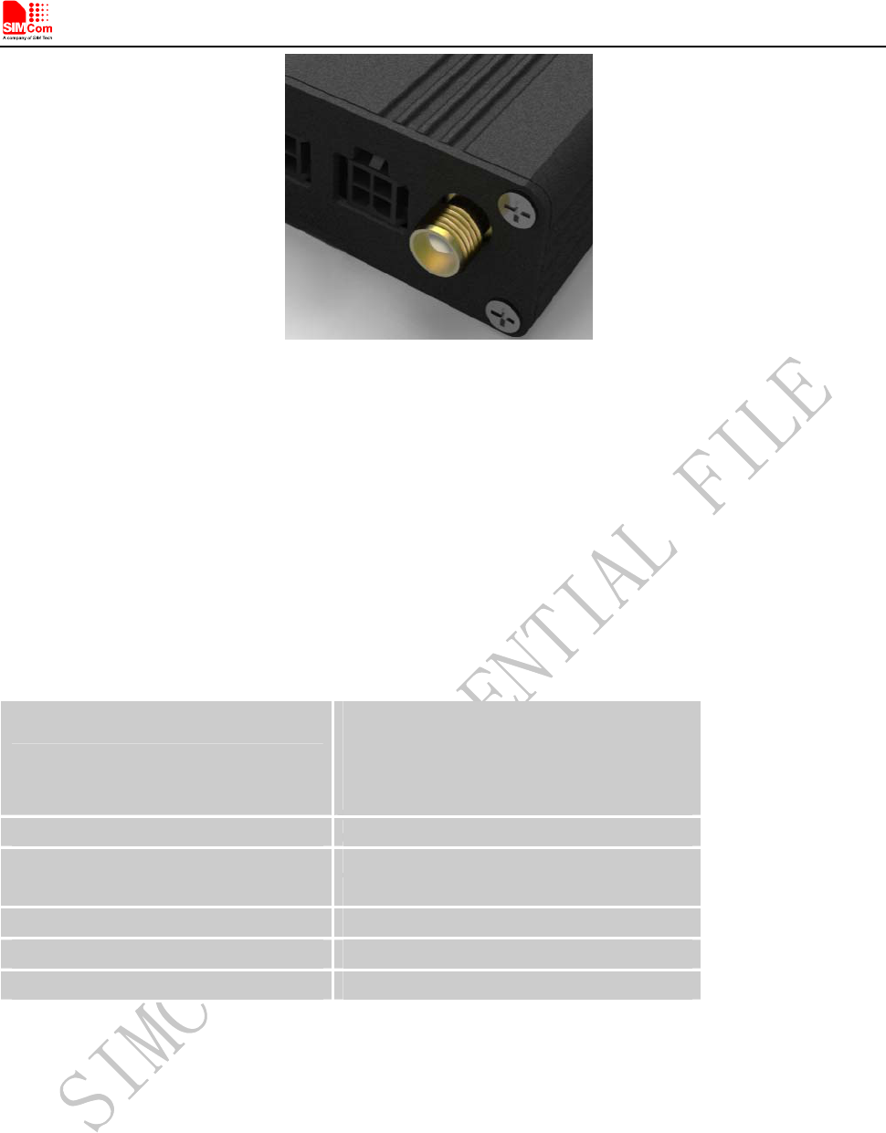
Smart Machine Smart Decision
Figure 17: Antenna interface
6.9.2 Antenna type
The antenna is a very important component in the system. Since the antenna transmits and receives
electromagnetic signal, and its efficiency depends on the antenna’s type, placement and the environment of the
antenna operating.
The recommended antenna specifications are showed in following table:
Table 17: antenna choosing consideration
Frequency range
GSM 850/900/1800/1900MHz
WCDMA 1900/850MHz(T5320A+G)
WCDMA 2100/900MHz(T5320E+G)
WCDMA 2100/850MHz(T5320J+G)
Impedance 50 ohm
Input power >33dBm (2W) peak power in GSM
>24dBm (0.25W) peak power in WCDMA
VSWR absolute max. ≤10:1
VSWR recommended ≤2:1
Gain < 3dBi
6.9.3 Antenna placement
The antenna performance is very easily influenced by other electronic devices. So the antenna placement should
be considered carefully as follow.
1. Place away from other electronic devices or other antennas.
2. Place far away from metal material.
3. Face the base station antenna directly if the signal strength is very weak.
T5320+G_User Guide_V1.01 28 2013-04-15
Smart Machine Smart Decision
T5320+G_User Guide_V1.01 29 2013-04-15
7 Electrical, Reliability and Radio Characteristics
7.1 Absolute Maximum Ratings
The absolute maximum ratings stated in following table are stress ratings under non-operating conditions. Stresses
beyond any of these limits will cause permanent damage to T5320+G.
Table 18: Absolute maximum ratings
Symbol Parameter Min Typ Max Unit
VBAT Power supply voltage 5 - 30 V
VI
* Input voltage -0.3 - 2.8 V
II
* Input current - - 6 mA
IO
* Output current - - 6 mA
*These parameters are for digital interface pins, such as GPIO, UART.
7.2 Recommended Operating Conditions
Table 19: Recommended operating conditions
Symbol Parameter Min Typ Max Unit
VBAT Power supply voltage 5 5 30 V
IIH High-level input current -10 - 10 uA
IIL Low-level input current -10 - 10 uA
VIH High-level input voltage 2.4 - - V
VIL Low-level input voltage - - 0.4 V
VOH High-level output voltage 2.6 - - V
VOL Low-level output voltage - - 0.1 V
TOPER Operating temperature -35 +25 +80 ℃
TSTG Storage temperature -40 +85 ℃
7.3 Electro-Static Discharge
T5320+G is an ESD sensitive component, so more attention should be paid to the procedure of handling and
packaging. The ESD test results are shown in the following table.
Table 20: The ESD characteristics (Temperature: 25 , Humidity℃: 45 %)
Pin Contact discharge Air discharge
Shell ±10KV ±15KV
Smart Machine Smart Decision
T5320+G_User Guide_V1.01 30 2013-04-15
RF&GPS interface ±10KV ±15KV
RS232 interface ±10KV ±15KV
Audio interface ±10KV ±15KV
SIM card holder ±10KV ±15KV
7.4 Operating frequency
The operating frequencies in GSM850, EGSM900, DCS, PCS and WCDMA modes are conform to the
GSM/WCDMA Specifications, shown as bellow.
Table 21: Operating frequency
Mode Freq.TX(MHz) Freq.RX(MHz) Channels(ARF
C)
TX-RX
offset
GSM-850 824.2 – 848.8 869.2 – 893.8 128 - 251 45 MHz
890.0-914.8 935.0-959.8 0–124 45M
E-GSM-900 880.2-889.8 925.2 - 934.8 975-1023 45M
DCS-1800 1710.2-1784.8 1805.2-1879.8 512–885 95 MHz
PCS-1900 1850.2 - 1909.8 1930.2 - 1989.8 512 - 810 80 MHz
WCDMA 2100 1920 - 1980 2110 - 2170 9612 – 9888 190 MHz
WCDMA 1900 1850 - 1910 1930 - 1990 9262 - 9538 80 MHz
WCDMA 900 880 - 915 925 - 960 2712 - 2863 45 MHz
WCDMA 850 824 - 849 869 - 894 4132 - 4233 45 MHz
7.5 Transmitter output power and receiver sensitivity
The T5320+G’s conducted transmitter output power and receiver sensitivity are shown as bellow:
Table 22: Transmitter output power and receiver sensitivity
Mode Power(dBm) Sensitivity(dBm)
GSM-850 +33 -106
E-GSM-900 +33 -106
DCS-1800 +30 -107
PCS-1900 +30 -107
WCDMA2100 +24 -106
WCDMA1900 +24 -106
WCDMA900 +24 -106
WCDMA850 +24 -106
Smart Machine Smart Decision
8 Software/ Firmware Upgrade
The software can be upgraded via the Micro USB interface with the help of tools provided by SIMCom,
8.1 Tool introduction
The tool name is “SIMCOM 3G Module Software update tools(QDL)”, which runs on the windows OS, customers
can upgrade software conveniently by it.
This tool is a single-road download tool, one terminal can be upgraded by it every time. SIMCom also provides
multi-road download tools for customer’s factory use. Contact SIMCom sales for support.
Please do not power off T5320+G during the upgrade.
8.2 Illustration of software updating
z Connect the Micro USB port of T5320+G to the PC USB port and connect the direct current source adapter.
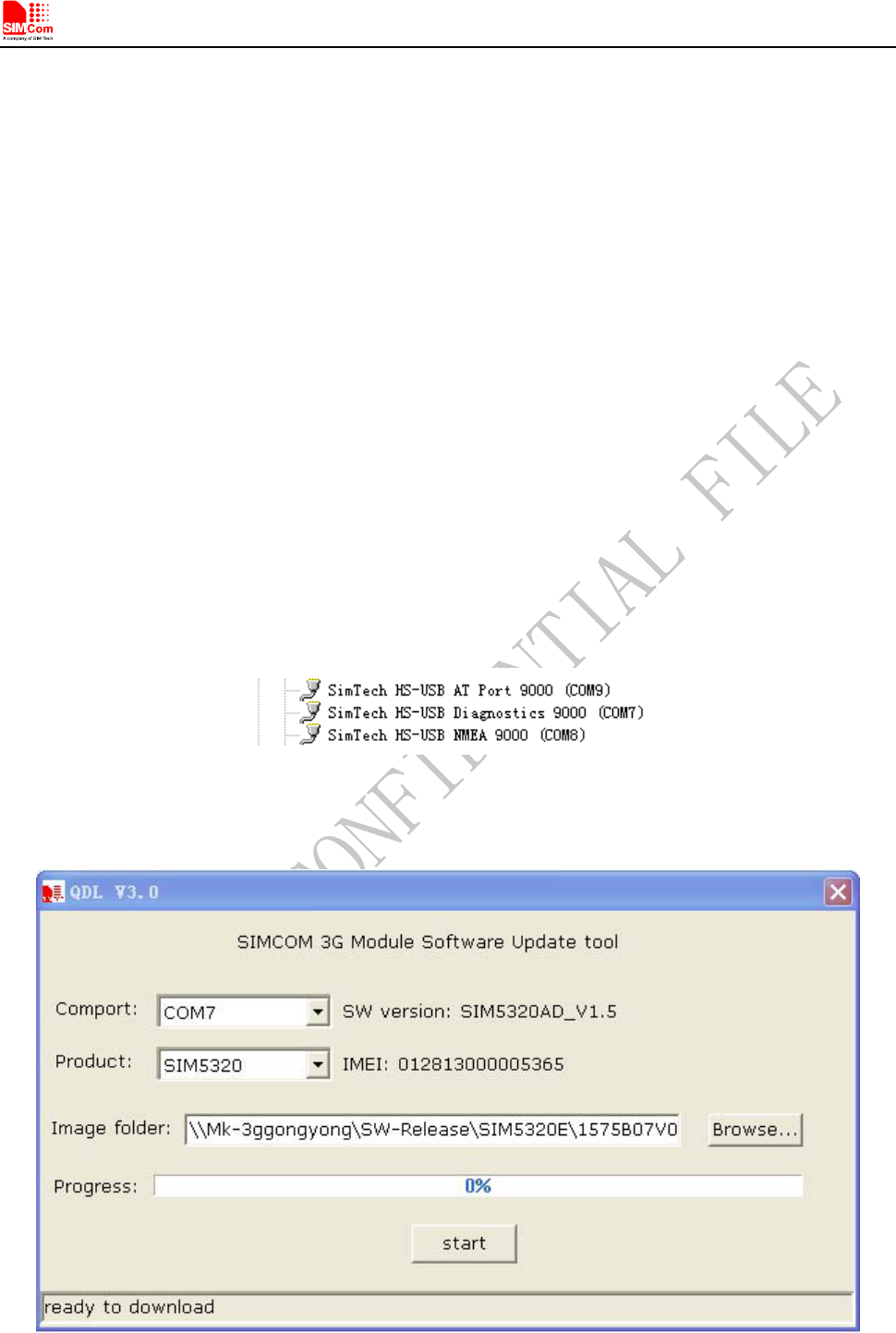
z Installing module USB driver on PC OS. USB interface is mapped to five virtual ports: “SIMTECH USB
Modem”, “SIMTECH NMEA Device”, “SIMTECH ATCOM Device”, “SIMTECH Diagnostics interface”
and “SIMTECH Wireless Ethernet Adapter”.
Figure 18: Virtual ports in computer manager window
z Open the tools, the main operation interface as the following figure shows:
Figure 19: QDL window
T5320+G_User Guide_V1.01 31 2013-04-15
Smart Machine Smart Decision
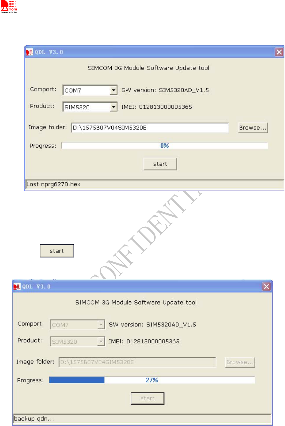
z Browse the source file
Figure 20: Browse the source file
z Software download
Click the button, then the window will change like the following figure shows.
Figure 21: click download button without power up
z Upgrade in proceeding
T5320+G_User Guide_V1.01 32 2013-04-15
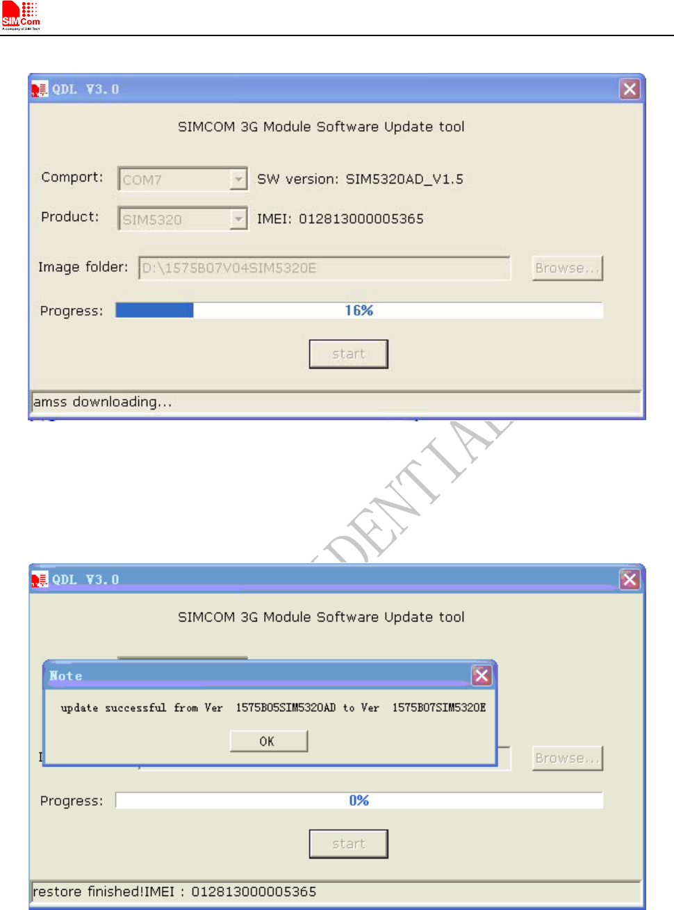
Smart Machine Smart Decision
Figure 22: Upgrade in proceeding
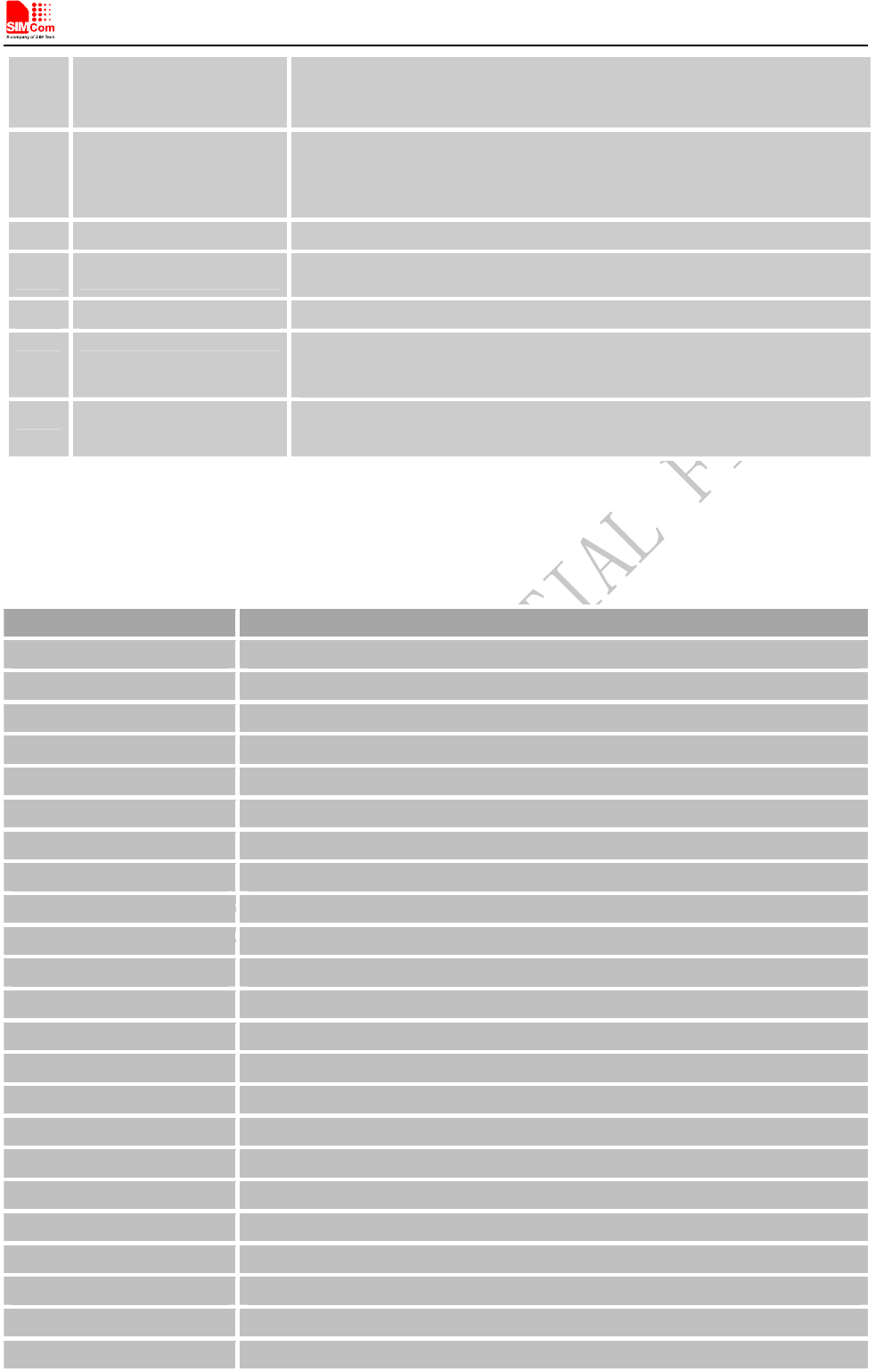
z Finish upgrading
Now the software is the new version, customer can check the software version by “ATI”.
Figure 23: Finish upgrading
T5320+G_User Guide_V1.01 33 2013-04-15

Smart Machine Smart Decision
T5320+G_User Guide_V1.01 34 2013-04-15

Smart Machine Smart Decision
T5320+G_User Guide_V1.01 35 2013-04-15
Appendix
A. Related Documents
Table 23: Related documents
SN Document name Remark
[1] SIM5320_ATC SIM5320 AT Command Manual
[2] SIM5xxx_GPIO_Applicat
ion_note
Applications Note About SIM5xxx_GPIO
[3] Audio Application Note
V1.01
Applications Note About T5320+G Audio
[4] ITU-T Draft new
recommendationV.25ter Serial asynchronous automatic dialing and control
[5] GSM 07.07 Digital cellular telecommunications (Phase 2+); AT command set for GSM
Mobile Equipment (ME)
[6] GSM 07.10 Support GSM 07.10 multiplexing protocol
[7] GSM 07.05
Digital cellular telecommunications (Phase 2+); Use of Data Terminal
Equipment – Data Circuit terminating Equipment (DTE – DCE) interface
for Short Message Service (SMS) and Cell Broadcast Service (CBS)
[8] GSM 11.14
Digital cellular telecommunications system (Phase 2+); Specification of
the SIM Application Toolkit for the Subscriber Identity Module – Mobile
Equipment (SIM – ME) interface
[9] GSM 11.11 Digital cellular telecommunications system (Phase 2+); Specification of
the Subscriber Identity Module – Mobile Equipment (SIM – ME) interface
[10] GSM 03.38 Digital cellular telecommunications system (Phase 2+); Alphabets and
language-specific information
[11] GSM 11.10 Digital cellular telecommunications system (Phase 2); Mobile Station
(MS) conformance specification; Part 1: Conformance specification
[12] 3GPP TS 51.010-1 Digital cellular telecommunications system (Release 5); Mobile Station
(MS) conformance specification
[13] 3GPP TS 34.124 Electromagnetic Compatibility (EMC) for mobile terminals and ancillary
equipment.
[14] 3GPP TS 34.121 Electromagnetic Compatibility (EMC) for mobile terminals and ancillary
equipment.
[15] 3GPP TS 34.123-1 Technical Specification Group Radio Access Network; Terminal
conformance specification; Radio transmission and reception (FDD)
[16] 3GPP TS 34.123-3 User Equipment (UE) conformance specification; Part 3: Abstract Test
Suites.
[17] EN 301 908-02 V2.2.1
Electromagnetic compatibility and Radio spectrum Matters
(ERM); Base Stations (BS) and User Equipment (UE) for
IMT-2000. Third Generation cellular networks; Part 2:
Smart Machine Smart Decision
T5320+G_User Guide_V1.01 36 2013-04-15
Harmonized EN for IMT-2000, CDMA Direct Spread
(UTRA FDD) (UE) covering essential requirements of article
3.2 of the R&TTE Directive
[18] EN 301 489-24 V1.2.1
Electromagnetic compatibility and Radio Spectrum Matters
Electromagnetic Compatibility (EMC) standard for radio equipment and
s
Part 24: Specific conditions for IMT-2000 CDMA Direct Spread (UT
R
Mobile and portable (UE) radio and ancillary equipment
[19] IEC/EN60950-1(2001) Safety of information technology equipment (2000)
[20] 3GPP TS 51.010-1 Digital cellular telecommunications system (Release 5); Mobile Stati
o
conformance specification
[21] GCF-CC V3.23.1 Global Certification Forum - Certification Criteria
[22] 2002/95/EC
Directive of the European Parliament and of the Council of 27 January 200
restriction of the use of certain hazardous substances in electrical and e
l
equipment (RoHS)
[23] SIM52xx_GPS_Applicati
on_Note
Applications Note About SIM5xxx GPS
B. Terms and Abbreviations
Table 24: Terms and Abbreviations
Abbreviation Description
ADC Analog-to-Digital Converter
AMR Adaptive Multi-Rate
AT Attention commands
CS Coding Scheme
CSD Circuit Switched Data
CTS Clear to Send
DTE Data Terminal Equipment (typically computer, terminal, printer)
DTR Data Terminal Ready
DTU Data Transmit Unit
DTX Discontinuous Transmission
EFR Enhanced Full Rate
EGSM Enhanced GSM
ESD Electrostatic Discharge
ETS European Telecommunication Standard
FR Full Rate
GPRS General Packet Radio Service
GSM Global Standard for Mobile Communications
HR Half Rate
IMEI International Mobile Equipment Identity
Li-ion Lithium-Ion
MO Mobile Originated
MS Mobile Station (GSM engine), also referred to as TE
MT Mobile Terminated
Smart Machine Smart Decision
PAP Password Authentication Protocol
PBCCH Packet Broadcast Control Channel
PCB Printed Circuit Board
PCL Power Control Level
PCS Personal Communication System, also referred to as GSM 1900
PDU Protocol Data Unit
PPP Point-to-point protocol
RF Radio Frequency
RMS Root Mean Square (value)
RTC Real Time Clock
RX Receive Direction
SIM Subscriber Identification Module
SMS Short Message Service
TE Terminal Equipment, also referred to as DTE
TX Transmit Direction
UART Universal Asynchronous Receiver & Transmitter
URC Unsolicited Result Code
USSD Unstructured Supplementary Service Data
Phonebook abbreviations
FD SIM fix dialing phonebook
LD SIM last dialing phonebook (list of numbers most recently dialed)
MC Mobile Equipment list of unanswered MT calls (missed calls)
ON SIM (or ME) own numbers (MSISDNs) list
RC Mobile Equipment list of received calls
SM SIM phonebook
NC Not connect
C. Safety Caution
Table 25: Safety caution
Marks Requirements
When in a hospital or other health care facility, observe the restrictions about the use of mobiles.
Switch the cellular terminal or mobile off, medical equipment may be sensitive to not operate
normally for RF energy interference.
Switch off the cellular terminal or mobile before boarding an aircraft. Make sure it is switched off.
The operation of wireless appliances in an aircraft is forbidden to prevent interference with
communication systems. Forget to think much of these instructions may lead to the flight safety or
offend against local legal action, or both.
Do not operate the cellular terminal or mobile in the presence of flammable gases or fumes. Switch
off the cellular terminal when you are near petrol stations, fuel depots, chemical plants or where
blasting operations are in progress. Operation of any electrical equipment in potentially explosive
atmospheres can constitute a safety hazard.
T5320+G_User Guide_V1.01 37 2013-04-15

Smart Machine Smart Decision
Your cellular terminal or mobile receives and transmits radio frequency energy while switched on.
RF interference can occur if it is used close to TV sets, radios, computers or other electric
equipment.
Road safety comes first! Do not use a hand-held cellular terminal or mobile when driving a
vehicle, unless it is securely mounted in a holder for hands free operation. Before making a call
with a hand-held terminal or mobile, park the vehicle.
GSM cellular terminals or mobiles operate over radio frequency signals and cellular networks and
cannot be guaranteed to connect in all conditions, for example no mobile fee or a invalid SIM card.
While you are in this condition and need emergent help, please remember using emergency calls.
In order to make or receive calls, the cellular terminal or mobile must be switched on and in a
service area with adequate cellular signal strength.
Some networks do not allow for emergency call if certain network services or phone features are in
use (e.g. lock functions, fixed dialing etc.). You may have to deactivate those features before you
can make an emergency call.
Also, some networks require that a valid SIM card be properly inserted in the cellular terminal or
mobile.
T5320+G_User Guide_V1.01 38 2013-04-15